computational investigation of hydro-mechanical effects on ...
computational investigation of hydro-mechanical effects on ...
computational investigation of hydro-mechanical effects on ...
Create successful ePaper yourself
Turn your PDF publications into a flip-book with our unique Google optimized e-Paper software.
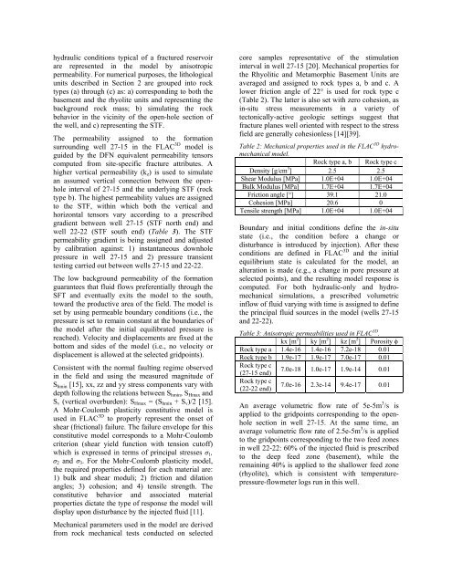
hydraulic c<strong>on</strong>diti<strong>on</strong>s typical <str<strong>on</strong>g>of</str<strong>on</strong>g> a fractured reservoir<br />
are represented in the model by anisotropic<br />
permeability. For numerical purposes, the lithological<br />
units described in Secti<strong>on</strong> 2 are grouped into rock<br />
types (a) through (c) as: a) corresp<strong>on</strong>ding to both the<br />
basement and the rhyolite units and representing the<br />
background rock mass; b) simulating the rock<br />
behavior in the vicinity <str<strong>on</strong>g>of</str<strong>on</strong>g> the open-hole secti<strong>on</strong> <str<strong>on</strong>g>of</str<strong>on</strong>g><br />
the well, and c) representing the STF.<br />
The permeability assigned to the formati<strong>on</strong><br />
surrounding well 27-15 in the FLAC 3D model is<br />
guided by the DFN equivalent permeability tensors<br />
computed from site-specific fracture attributes. A<br />
higher vertical permeability (k z ) is used to simulate<br />
an assumed vertical c<strong>on</strong>necti<strong>on</strong> between the openhole<br />
interval <str<strong>on</strong>g>of</str<strong>on</strong>g> 27-15 and the underlying STF (rock<br />
type b). The highest permeability values are assigned<br />
to the STF, within which both the vertical and<br />
horiz<strong>on</strong>tal tensors vary according to a prescribed<br />
gradient between well 27-15 (STF north end) and<br />
well 22-22 (STF south end) (Table 3). The STF<br />
permeability gradient is being assigned and adjusted<br />
by calibrati<strong>on</strong> against: 1) instantaneous downhole<br />
pressure in well 27-15 and 2) pressure transient<br />
testing carried out between wells 27-15 and 22-22.<br />
The low background permeability <str<strong>on</strong>g>of</str<strong>on</strong>g> the formati<strong>on</strong><br />
guarantees that fluid flows preferentially through the<br />
SFT and eventually exits the model to the south,<br />
toward the productive area <str<strong>on</strong>g>of</str<strong>on</strong>g> the field. The model is<br />
set by using permeable boundary c<strong>on</strong>diti<strong>on</strong>s (i.e., the<br />
pressure is set to remain c<strong>on</strong>stant at the boundaries <str<strong>on</strong>g>of</str<strong>on</strong>g><br />
the model after the initial equilibrated pressure is<br />
reached). Velocity and displacements are fixed at the<br />
bottom and sides <str<strong>on</strong>g>of</str<strong>on</strong>g> the model (i.e., no velocity or<br />
displacement is allowed at the selected gridpoints).<br />
C<strong>on</strong>sistent with the normal faulting regime observed<br />
in the field and using the measured magnitude <str<strong>on</strong>g>of</str<strong>on</strong>g><br />
S hmin [15], xx, zz and yy stress comp<strong>on</strong>ents vary with<br />
depth following the relati<strong>on</strong>s between S hmin , S Hmax and<br />
S v (vertical overburden): S Hmax = (S hmin + S v )/2 [15].<br />
A Mohr-Coulomb plasticity c<strong>on</strong>stitutive model is<br />
used in FLAC 3D to properly represent the <strong>on</strong>set <str<strong>on</strong>g>of</str<strong>on</strong>g><br />
shear (fricti<strong>on</strong>al) failure. The failure envelope for this<br />
c<strong>on</strong>stitutive model corresp<strong>on</strong>ds to a Mohr-Coulomb<br />
criteri<strong>on</strong> (shear yield functi<strong>on</strong> with tensi<strong>on</strong> cut<str<strong>on</strong>g>of</str<strong>on</strong>g>f)<br />
which is expressed in terms <str<strong>on</strong>g>of</str<strong>on</strong>g> principal stresses σ 1 ,<br />
σ 2 and σ 3 . For the Mohr-Coulomb plasticity model,<br />
the required properties defined for each material are:<br />
1) bulk and shear moduli; 2) fricti<strong>on</strong> and dilati<strong>on</strong><br />
angles; 3) cohesi<strong>on</strong>; and 4) tensile strength. The<br />
c<strong>on</strong>stitutive behavior and associated material<br />
properties dictate the type <str<strong>on</strong>g>of</str<strong>on</strong>g> resp<strong>on</strong>se the model will<br />
display up<strong>on</strong> disturbance by the injected fluid [11].<br />
Mechanical parameters used in the model are derived<br />
from rock <str<strong>on</strong>g>mechanical</str<strong>on</strong>g> tests c<strong>on</strong>ducted <strong>on</strong> selected<br />
core samples representative <str<strong>on</strong>g>of</str<strong>on</strong>g> the stimulati<strong>on</strong><br />
interval in well 27-15 [20]. Mechanical properties for<br />
the Rhyolitic and Metamorphic Basement Units are<br />
averaged and assigned to rock types a, b and c. A<br />
lower fricti<strong>on</strong> angle <str<strong>on</strong>g>of</str<strong>on</strong>g> 22° is used for rock type c<br />
(Table 2). The latter is also set with zero cohesi<strong>on</strong>, as<br />
in-situ stress measurements in a variety <str<strong>on</strong>g>of</str<strong>on</strong>g><br />
tect<strong>on</strong>ically-active geologic settings suggest that<br />
fracture planes well oriented with respect to the stress<br />
field are generally cohesi<strong>on</strong>less [14][39].<br />
Table 2: Mechanical properties used in the FLAC 3D <str<strong>on</strong>g>hydro</str<strong>on</strong>g><str<strong>on</strong>g>mechanical</str<strong>on</strong>g><br />
model.<br />
Rock type a, b Rock type c<br />
Density [g/cm 3 ] 2.5 2.5<br />
Shear Modulus [MPa] 1.0E+04 1.0E+04<br />
Bulk Modulus [MPa] 1.7E+04 1.7E+04<br />
Fricti<strong>on</strong> angle [°] 39.1 21.0<br />
Cohesi<strong>on</strong> [MPa] 20.6 0<br />
Tensile strength [MPa] 1.0E+04 1.0E+04<br />
Boundary and initial c<strong>on</strong>diti<strong>on</strong>s define the in-situ<br />
state (i.e., the c<strong>on</strong>diti<strong>on</strong> before a change or<br />
disturbance is introduced by injecti<strong>on</strong>). After these<br />
c<strong>on</strong>diti<strong>on</strong>s are defined in FLAC 3D and the initial<br />
equilibrium state is calculated for the model, an<br />
alterati<strong>on</strong> is made (e.g., a change in pore pressure at<br />
selected points), and the resulting model resp<strong>on</strong>se is<br />
computed. For both hydraulic-<strong>on</strong>ly and <str<strong>on</strong>g>hydro</str<strong>on</strong>g><str<strong>on</strong>g>mechanical</str<strong>on</strong>g><br />
simulati<strong>on</strong>s, a prescribed volumetric<br />
inflow <str<strong>on</strong>g>of</str<strong>on</strong>g> fluid varying with time is assigned to define<br />
the principal fluid sources in the model (wells 27-15<br />
and 22-22).<br />
Table 3: Anisotropic permeabilities used in FLAC 3D .<br />
kx [m 2 ] ky [m 2 ] kz [m 2 ] Porosity ϕ<br />
Rock type a 1.4e-16 1.4e-16 7.2e-18 0.01<br />
Rock type b 1.9e-17 1.9e-17 7.0e-17 0.01<br />
Rock type c<br />
(27-15 end)<br />
7.0e-18 1.0e-17 1.9e-14 0.01<br />
Rock type c<br />
(22-22 end)<br />
7.0e-16 2.3e-14 9.4e-17 0.01<br />
An average volumetric flow rate <str<strong>on</strong>g>of</str<strong>on</strong>g> 5e-5m 3 /s is<br />
applied to the gridpoints corresp<strong>on</strong>ding to the openhole<br />
secti<strong>on</strong> in well 27-15. At the same time, an<br />
average volumetric flow rate <str<strong>on</strong>g>of</str<strong>on</strong>g> 2.5e-5m 3 /s is applied<br />
to the gridpoints corresp<strong>on</strong>ding to the two feed z<strong>on</strong>es<br />
in well 22-22: 60% <str<strong>on</strong>g>of</str<strong>on</strong>g> the injected fluid is prescribed<br />
to the deep feed z<strong>on</strong>e (basement), while the<br />
remaining 40% is applied to the shallower feed z<strong>on</strong>e<br />
(rhyolite), which is c<strong>on</strong>sistent with temperaturepressure-flowmeter<br />
logs run in this well.


