Assignment 3.pdf - UBC Mechanical Engineering
Assignment 3.pdf - UBC Mechanical Engineering
Assignment 3.pdf - UBC Mechanical Engineering

You also want an ePaper? Increase the reach of your titles
YUMPU automatically turns print PDFs into web optimized ePapers that Google loves.
l<br />
v<br />
= = the lever arm ratio of the handle rocker<br />
lh<br />
m = equivalent lumped mass of the valve flapper and the lift rod<br />
k = stiffness of spring action on the valve flapper.<br />
The damping force f NLD on the valve is assumed quadratic and is given by<br />
f = av v<br />
NLD VLD VLD<br />
where, the positive parameter:<br />
a = a u for upward motion of the flapper (v NLD ≥ 0)<br />
= a d for downward motion of the flapper (v NLD < 0)<br />
with a u >> a d<br />
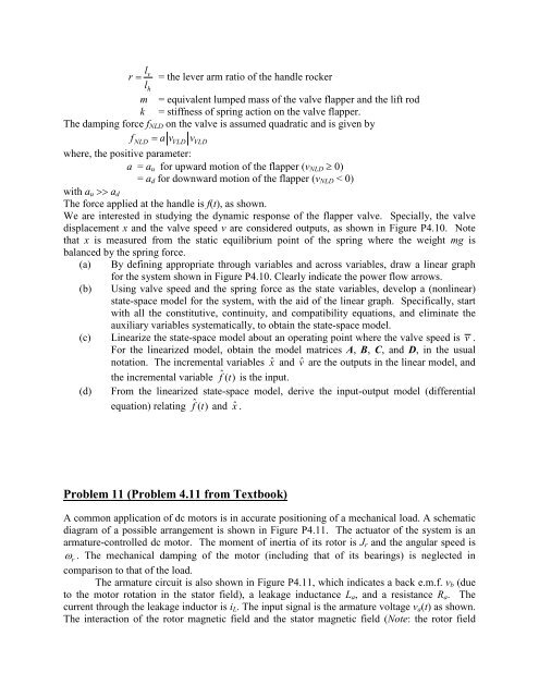
The force applied at the handle is f(t), as shown.<br />
We are interested in studying the dynamic response of the flapper valve. Specially, the valve<br />
displacement x and the valve speed v are considered outputs, as shown in Figure P4.10. Note<br />
that x is measured from the static equilibrium point of the spring where the weight mg is<br />
balanced by the spring force.<br />
(a) By defining appropriate through variables and across variables, draw a linear graph<br />
(b)<br />
for the system shown in Figure P4.10. Clearly indicate the power flow arrows.<br />
Using valve speed and the spring force as the state variables, develop a (nonlinear)<br />
state-space model for the system, with the aid of the linear graph. Specifically, start<br />
with all the constitutive, continuity, and compatibility equations, and eliminate the<br />
auxiliary variables systematically, to obtain the state-space model.<br />
(c) Linearize the state-space model about an operating point where the valve speed is v .<br />
For the linearized model, obtain the model matrices A, B, C, and D, in the usual<br />
notation. The incremental variables ˆx and ˆv are the outputs in the linear model, and<br />
(d)<br />
the incremental variable f ˆ( t ) is the input.<br />
From the linearized state-space model, derive the input-output model (differential<br />
equation) relating f ˆ( t ) and ˆx .<br />
Problem 11 (Problem 4.11 from Textbook)<br />
A common application of dc motors is in accurate positioning of a mechanical load. A schematic<br />
diagram of a possible arrangement is shown in Figure P4.11. The actuator of the system is an<br />
armature-controlled dc motor. The moment of inertia of its rotor is J r and the angular speed is<br />
ω r . The mechanical damping of the motor (including that of its bearings) is neglected in<br />
comparison to that of the load.<br />
The armature circuit is also shown in Figure P4.11, which indicates a back e.m.f. v b (due<br />
to the motor rotation in the stator field), a leakage inductance L a , and a resistance R a . The<br />
current through the leakage inductor is i L . The input signal is the armature voltage v a (t) as shown.<br />
The interaction of the rotor magnetic field and the stator magnetic field (Note: the rotor field