Assignment 3.pdf - UBC Mechanical Engineering
Assignment 3.pdf - UBC Mechanical Engineering
Assignment 3.pdf - UBC Mechanical Engineering

You also want an ePaper? Increase the reach of your titles
YUMPU automatically turns print PDFs into web optimized ePapers that Google loves.
(d)<br />
What is the number of unknown variables, both state and auxiliary, (expressed in<br />
terms of b and s)? Verify that this is equal to the number available equations, and<br />
hence the problem is solvable.<br />
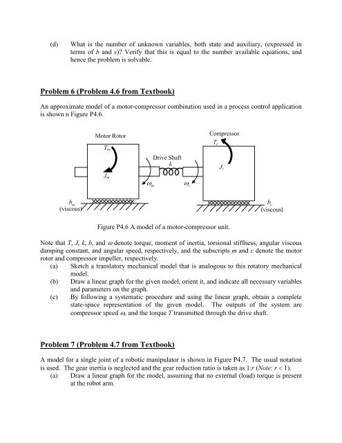
Problem 6 (Problem 4.6 from Textbook)<br />
An approximate model of a motor-compressor combination used in a process control application<br />
is shown n Figure P4.6.<br />
Motor Rotor<br />
T m<br />
Drive Shaft<br />
k<br />
Compressor<br />
T c<br />
J c<br />
J m<br />
ω<br />
m<br />
ω<br />
c<br />
b<br />
m<br />
(viscous)<br />
b<br />
c<br />
(viscous)<br />
Figure P4.6 A model of a motor-compressor unit.<br />
Note that T, J, k, b, and ω denote torque, moment of inertia, torsional stiffness, angular viscous<br />
damping constant, and angular speed, respectively, and the subscripts m and c denote the motor<br />
rotor and compressor impeller, respectively.<br />
(a) Sketch a translatory mechanical model that is analogous to this rotatory mechanical<br />
model.<br />
(b) Draw a linear graph for the given model, orient it, and indicate all necessary variables<br />
and parameters on the graph.<br />
(c) By following a systematic procedure and using the linear graph, obtain a complete<br />
state-space representation of the given model. The outputs of the system are<br />
compressor speed ω c and the torque T transmitted through the drive shaft.<br />
Problem 7 (Problem 4.7 from Textbook)<br />
A model for a single joint of a robotic manipulator is shown in Figure P4.7. The usual notation<br />
is used. The gear inertia is neglected and the gear reduction ratio is taken as 1:r (Note: r < 1).<br />
(a) Draw a linear graph for the model, assuming that no external (load) torque is present<br />
at the robot arm.