PIA-662Pro
PIA-662Pro
PIA-662Pro

Create successful ePaper yourself
Turn your PDF publications into a flip-book with our unique Google optimized e-Paper software.
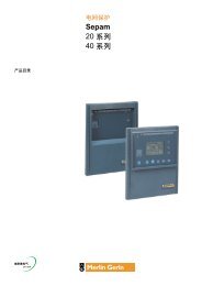
<strong>PIA</strong>-<strong>662Pro</strong><br />
Full-size PICMG Socket 370 Pentium-III /<br />
Celeron PC-133 CPU Card<br />
with Flat Panel / CRT SVGA, Fast Ethernet<br />
Interface and DiskOnChip Socket
Copyright © 2000, 2001<br />
All Rights Reserved.<br />
Manual edition 1.1, June 2001<br />
The information in this document is subject to change without prior notice in<br />
order to improve the reliability, design and function. It does not represent a<br />
commitment on the part of the manufacturer.<br />
Under no circumstances will the manufacturer be liable for any direct,<br />
indirect, special, incidental, or consequen-tial damages arising from the use or<br />
inability to use the product or documentation, even if advised of the possibility<br />
of such damages.<br />
This document contains proprietary information protected by copyright. All<br />
rights are reserved. No part of this manual may be reproduced by any<br />
mechanical, electronic, or other means in any form without prior written<br />
permission of the manufacturer.<br />
Trademarks<br />
DiskOnChip ® 2000 and TrueFFS are registered trademarks of M-Systems Inc..<br />
PC is a registered trademark of International Business Machines Corporation.<br />
Intel is a registered trademark of Intel Corporation. AWARD is a registered<br />
trademark of Award Software International, Inc. Other product names<br />
mentioned herein are used for identification purposes only and may be<br />
trademarks and/or registered trademarks of their respective companies.<br />
Part number : MPRT-UM-<strong>PIA</strong>662PRO-11
Table of Contents<br />
Introduction ...................................................................................1<br />
Specifications ...............................................................................2<br />
Component Location ....................................................................4<br />
Ordering Codes ................................................................................................... 5<br />
Board Layout Front ......................................................................6<br />
Jumper/Connector Quick Reference ...........................................7<br />
CPU and CMOS Jumper Settings ................................................8<br />
FSB/Core Ration (Auto-detect) ........................................................................... 8<br />
FSB speed (JFSB1, JFSB2) ................................................................................ 8<br />
CMOS Operation (JRTC) ...................................................................................... 8<br />
Watchdog Timer ...........................................................................9<br />
Mode Setting (J3) ................................................................................................ 9<br />
Time-out Setting (SWDT) ..................................................................................... 9<br />
Programming Example ....................................................................................... 10<br />
DiskOnChip ® 2000 Flash Disk ..................................................... 11<br />
Installation Instructions ....................................................................................... 11<br />
Power Connectors/Selectors ..................................................... 12<br />
Power Connector (PWRCON1, ATXCON) ......................................................... 12<br />
LCD Voltage Selection (JVOLT) ........................................................................ 12<br />
CPU Fan Connector (CPUFAN) .......................................................................... 13<br />
Chassis Auxilary Fan Connector (CHASFAN) .................................................. 13<br />
Single Chip Fast Ethernet Controller (opt.) .............................. 14<br />
LAN Port (LAN) ................................................................................................. 14<br />
Enable/disable LAN Controller (JLAN) ............................................................. 14<br />
LAN LED Indicator (LED) ................................................................................... 14<br />
Serial Port Selection (RS-232/485) ............................................ 15<br />
COM RS-232/485 Selection (J485) ................................................................... 15<br />
Interface Connectors HDD, FDD ................................................. 16<br />
Floppy Disk Drive (Floppy) ................................................................................ 16<br />
Enhanced IDE Connector (IDE1, IDE2) .............................................................. 17
Peripheral Ports.......................................................................... 18<br />
Parallel Port (Printer) .......................................................................................... 18<br />
Serial Ports (JCOM1, JCOM2) ........................................................................... 19<br />
Serial Ports (RS485) .......................................................................................... 19<br />
USB Port (USB) ................................................................................................. 19<br />
CRT SVGA (VGA) ............................................................................................. 20<br />
Flat Panel VGA (LCD) ........................................................................................ 20<br />
Keyboard (AT-KB) ............................................................................................. 21<br />
PS/2 Keyboard ................................................................................................... 21<br />
PS/2 Mouse ........................................................................................................ 21<br />
IrDA (SIR) ........................................................................................................... 21<br />
Soundblaster Compatibillity Connector (SB_LINK) ........................................... 21<br />
Switches and Indicators ............................................................. 22<br />
Software Setup ........................................................................... 23<br />
Upgrading Windows 95 ..................................................................................... 23<br />
Driver Installation ............................................................................................... 24<br />
System Monitor under Windows 95/98/NT ...................................................... 25<br />
VGA Flat Panel & Wiring Diagrams ............................................ 26<br />
Flat Panel Connector (LCD) ............................................................................... 27<br />
NEC NL8060AC26-04 wiring ............................................................................. 27<br />
NEC NL8060BC31-02 wiring ............................................................................. 28<br />
LG LG-LP121S1 wiring ..................................................................................... 29<br />
TOSHIBA LTM10C039 wiring ............................................................................. 30<br />
KCB104VG2BA-A01 wiring .............................................................................. 31<br />
AWARD BIOS Setup .................................................................... 33<br />
Standard CMOS Setup ....................................................................................... 34<br />
BIOS Features Setup ......................................................................................... 37<br />
Chipset Features Setup ..................................................................................... 40<br />
Power Management Setup ................................................................................ 44<br />
Integrated Peripherals ....................................................................................... 46<br />
PNP/PCI Configuration ........................................................................................ 48<br />
POST Codes ................................................................................ 50<br />
Howto : Flash the BIOS .............................................................. 55<br />
What if things go wrong .................................................................................... 56<br />
Warranty ...................................................................................... 57
Introduction<br />
The <strong>PIA</strong>-<strong>662Pro</strong> is an All-in-One single board computer with a Flat Panel / CRT<br />
controller, a Fast Ethernet interface and a socket 370 for a Intel FC-PGA<br />
Pentium ® -III, Intel FC-PGA / PPGA Celeron and Via Cyrix-III CPU.<br />
Flat Panel / CRT Display<br />
The CHIPS C&T69000 is a highly integrated graphics/flat panel controller<br />
integrating 2MB of SDRAM, graphics, flat panel, and CRT control logic on the<br />
same die. The C&T69000 delivers super 2D video performance and consumes<br />
minimal power<br />
10/100 Mbps Networking<br />
A PCI 10BASE-T/100BASE-TX Fast Ethernet interface is included for high<br />
speed networking.<br />
Monitoring and Alarm<br />
The <strong>PIA</strong>-<strong>662Pro</strong> includes a multitude of monitoring and alarm functions to<br />
protect your board from high temperatures or over voltage exposure.<br />
DiskOnChip ® 2000<br />
The <strong>PIA</strong>-<strong>662Pro</strong>'s SSD socket accommodates a DiskOnChip ® 2000, a new<br />
generation of high performance single-chip Flash Disks up to 288 MB.<br />
Watchdog Timer<br />
A 6-level Watchdog Timer can invoke an Active NMI or RESET the CPU when<br />
your application loses control over the system.<br />
<strong>PIA</strong>-<strong>662Pro</strong> User's Manual<br />
1
Specifications<br />
• CPU Socket 370 : Intel ® Pentium ® III, Intel ® Celeron and VIA Cyrix ® III<br />
• Chipset : VT82C693A NB and VT82C596B SB (VIA Apollo Pro133) with<br />
133 FSB (CPU speed up to 1.13 GHz) and 133 MHz Memory Bus<br />
with support for PC-133 SDRAM<br />
• BIOS : Y2K compliant AWARD Flash BIOS supports NCR SCSI, Green&Soft<br />
Off function, LS120 and Multiple boot-up<br />
• Green Function : power saving supported in BIOS. DOZE / STANDBY /<br />
SUSPEND modes, ACPI & APM<br />
• Secondary Cache : Integrated on CPU<br />
• DRAM Memory : up to 1.5 GB of SDRAM in three 168-pin DIMM sockets<br />
(supports PC-133 SDRAM with ECC)<br />
• PCI Enhanced IDE with Ultra DMA : supports 2 ports and up to 4 ATAPI<br />
devices. PIO mode 3/4 and Bus-Master. Ultra DMA transfer rates of 66<br />
MB/sec, Multiword DMA Mode 2 transfer<br />
• Bus Interface : PCI and ISA, complies with PICMG standard<br />
• Data Bus : PCI - 32-bit, ISA - 16 bit<br />
• Bus Speeds : PCI - 33.3 MHz, ISA - 8.3 MHz<br />
• DMA Cchannels : 8237 x 2 (7-channels)<br />
• Interrupt Levels : 15<br />
• PCI Enhanced IDE with Ultra DMA : supports two ports and up to four<br />
ATAPI devices. Supports PIO mode 3/4 and Bus-Master. Ultra DMA transfer<br />
rates of 33/66 MB/sec, Multiword DMA Mode 2 transfer<br />
• Watchdog Timer : generates a system RESET or Active NMI<br />
The timer interval is: 1, 2, 10, 20, 110 and 220 seconds .<br />
• Real-time Clock : Benchmarq bq3287 AMT (or compatible) with lithium<br />
battery backup for 10 years of data retention. CMOS data backup of BIOS<br />
setup and BIOS default.<br />
• Keyboard and Mouse Connectors :<br />
6-pin mini DIN for PS/2 mouse, 6-pin mini DIN for Keyboard, 5-pin internal<br />
header for AT Keyboard<br />
High Speed Multi I/O<br />
• Chipset : Winbond W83977EF-AW<br />
• Serial Ports : one internal/external high speed RS-232 port COM1 (for<br />
DVL version only internal connector),<br />
one internal high speed RS-232/485 port COM2 (jumper selectable). Both<br />
with 16C550 UART and 16 byte FIFO.<br />
• USB : two onboard USB ports (12 Mb/s and 1.5 Mb/s)<br />
• SIR Interface : 5-pin IrDA TX/RX header<br />
• Floppy Disk Drive Interface : up to two floppy drives, 5¼ " (360 KB or<br />
1.2 MB) and 3½ " (720 KB, 1.44 MB or 2.88 MB). BIOS enabled/disabled<br />
• Bi-directional Parallel Port : SPP, EPP and ECP mode.<br />
2 <strong>PIA</strong>-<strong>662Pro</strong> User's Manual
Flat Panel / CRT 2D Graphics Accelerator<br />
• Chipset : CHIPS C&T69000 HiQVideo, 2 MB integrated SDRAM on chip<br />
• BIOS : combined with system BIOS<br />
• Display Type : CRT, TFT, DSTN, SSTN, EL, Plasma<br />
Quarter VGA, VGA, SVGA, XGA and SXGA<br />
• Display Mode<br />
Resolution Colors Refresh Rate<br />
1280 x 1024 256 60Hz<br />
1024 x 768 64K 60,75,85 Hz<br />
800 x 600 262K 60,75,85 Hz<br />
640 x 480 262K 60,75,85 Hz<br />
• Connectors : external 15-pin D-type female for CRT and onboard 50-pin<br />
box header for Flat Panel display<br />
10BASE-T/100BASE-TX PCI Ethernet<br />
• Chipset: Realtek RTL8139B or compatible<br />
• Type : 10BASE-T / 100BASE-TX<br />
• Connector : external RJ-45 on bracket<br />
• Monitoring LEDs: TX indicator, Network activity indicator<br />
• Power Saving: "Wake-up on LAN" function supported in BIOS<br />
Flash Disk DiskOnChip ® 2000<br />
• Package : Single Chip Flash Disk in 32-pin DIP JEDEC<br />
• Capacity : up to 288 MB<br />
• Data Reliability : ECC/EDC error correction<br />
• Memory Window : 8 KByte<br />
Environmental and Power<br />
• Power Requirements : +5 V (4.75 ~5.25 V) @ 4.2A<br />
(366 MHz Celeron CPU and 64 MB SDRAM), ±12 V<br />
• CPU Power : onboard PWM switching power supply for autodetects CPU<br />
core voltage<br />
• System Monitoring and Alarm: CPU and System<br />
temperature, system voltage and cooling fan RPM.<br />
• Board Dimensions : 338 mm x 122 mm<br />
• Board Weight : 0.42 Kg.<br />
• Operating Temperature: 0 to 55°C<br />
<strong>PIA</strong>-<strong>662Pro</strong> User's Manual<br />
3
Component Location<br />
VGA<br />
PS/2<br />
Mouse<br />
LAN+<br />
LED<br />
PS/2<br />
Keyboard<br />
FDD<br />
Power<br />
Connector<br />
Parallel<br />
Port<br />
COM1<br />
COM2<br />
DiskOnChip<br />
IDE1<br />
IDE2<br />
LCD<br />
SVGA<br />
System<br />
Temperature<br />
Sensor<br />
3 DIMM<br />
sockets<br />
168-pin<br />
Socket 370<br />
for Pentium III,<br />
Intel Celeron<br />
and Via Cyrix-III<br />
processor up<br />
to 1.13 GHz<br />
CPU<br />
Temperature<br />
Sensor<br />
4 <strong>PIA</strong>-<strong>662Pro</strong> User's Manual
Warning<br />
Single Board Computers and their components contain very<br />
delicate Integrated Circuits (IC). To protect the Single Board<br />
Computer and its components against damage from static<br />
electricity, you should always follow the following precautions<br />
when handling it :<br />
1. Disconnect your Single Board Computer from the power source<br />
when you want to work on the inside<br />
2. Hold the board by the edges and try not to touch the IC chips, leads<br />
or circuitry<br />
3. Use a grounded wrist strap when handling computer components.<br />
4. Place components on a grounded antistatic pad or on the bag that<br />
came with the Single Board Computer, whenever components are<br />
separated from the system<br />
Ordering Codes<br />
<strong>PIA</strong>-<strong>662Pro</strong>/DVL :<br />
<strong>PIA</strong>-<strong>662Pro</strong>/DV<br />
Full-size PICMG-bus Socket 370 Pentium III / Celeron<br />
PC-133 CPU Card with Flat Panel / CRT SVGA, Fast<br />
Ethernet and DiskOnChip Socket<br />
Full-size PICMG-bus Socket 370 Pentium III / Celeron<br />
PC-133 CPU Card with Flat Panel / CRT SVGA<br />
and DiskOnChip Socket<br />
<strong>PIA</strong>-<strong>662Pro</strong> User's Manual<br />
5
Board Layout Front<br />
IDE1<br />
IDE2<br />
Printer JCOM2 JCOM1<br />
Floppy<br />
2 CHASFAN<br />
PWRCON1<br />
ATXCON<br />
J485<br />
SIR<br />
RS485<br />
USB<br />
O N<br />
1 2 3 4<br />
LCD<br />
J3<br />
JVOLT<br />
SWDT<br />
VGA<br />
W83977EF-AW<br />
Winbond<br />
DIMM3<br />
2<br />
1<br />
1<br />
1<br />
1<br />
PS/2<br />
Mouse<br />
1<br />
50,000<br />
MHz<br />
2 6<br />
1 5<br />
J2<br />
DiskOnChip ' 2000<br />
socket<br />
SB-link<br />
LAN<br />
JRTC<br />
JLAN<br />
DIMM2<br />
Benchmarq<br />
AW ARD<br />
1 3<br />
.<br />
PCI PnP 686<br />
1 5<br />
PS/2<br />
KB<br />
DIMM1<br />
AT-KB<br />
14.318<br />
JFRNT<br />
JFRNT<br />
JFSB1<br />
JFSB2<br />
PGA 370<br />
<strong>PIA</strong>-<strong>662Pro</strong><br />
CPUFAN<br />
1<br />
3<br />
VT82C596B<br />
"Southbridge"<br />
VT82C693A<br />
"Northbridge"<br />
1 3<br />
1 3<br />
6 <strong>PIA</strong>-<strong>662Pro</strong> User's Manual
Jumper/Connector Quick Reference<br />
Jumpers<br />
JFSB<br />
FSB speed<br />
JFSB1 JFSB2 FSB Speed<br />
2-3 2-3 66 MHz<br />
1-2 2-3 100 MHz<br />
1-2 1-2 133 MHz<br />
open open Auto Detect<br />
JRTC RTC/CMOS Operation<br />
1-2 -> Clear<br />
2-3 -> Normal Operation<br />
J2 DiskOnChip Address<br />
3-4 -> D8000h<br />
open -> Disabled<br />
J3 Watchdog Active Mode<br />
1-2 -> System RESET<br />
2-3 -> active NMI<br />
off -> Disabled<br />
SWDT Watchdog Timer Timeout<br />
1 2 3 4 Sec<br />
off off on off 1<br />
off off on on 2<br />
off on off off 10<br />
off on off on 20<br />
on off off off 110<br />
on off off on 220<br />
J485<br />
COM2 RS-232/485 Mode<br />
1-2 -> RS-232<br />
2-3 -> RS-485<br />
JLAN Ethernet Function<br />
1-2 -> Enabled<br />
2-3 -> Disabled<br />
JVOLT LCD V CC<br />
Selection<br />
1-2 -> 5 Volt<br />
2-3 -> 3.3 Volt<br />
Connectors<br />
CHASFAN<br />
CPUFAN<br />
SB_LINK<br />
Chassis Fan Power<br />
CPU Fan Power<br />
16-bit Soundblaster<br />
compatibility signals<br />
VGA CRT SVGA<br />
LCD Flat Panel SVGA<br />
FLOPPY FDD interface<br />
IDE1 Primary IDE<br />
IDE2 Secondary IDE<br />
PRINTER LPT1, Parallel PORT<br />
JCOM1 COM 1, RS-232<br />
JCOM2 COM2 in RS-232 mode<br />
RS485 COM2 in RS-485 mode<br />
SIR IrDA Header<br />
USB Primary/Secondary USB<br />
ATKB AT Keyboard<br />
PS2KB PS/2 Keyboard<br />
PS2MOUSE PS/2 Mouse<br />
PWRCON1 Power Connector<br />
ATXCON ATX Signal Connector<br />
Jumper Color<br />
Green :<br />
Red :<br />
Yellow :<br />
CPU Speed Ratio<br />
Voltage Settings<br />
General configuration<br />
<strong>PIA</strong>-<strong>662Pro</strong> User's Manual<br />
7
CPU and CMOS Jumper Settings<br />
FSB/Core Ration (Auto-detect)<br />
The FSB/Core ratio has been prefixed inside the Pentium-II/III and Celeron<br />
CPUs by Intel. The prefixed ratio is auto-detected by the <strong>PIA</strong>-<strong>662Pro</strong>.<br />
CPU Frequency is ratio multiplied by FSB speed. The FSB value can be set by<br />
jumper to 66, 100 or 133 depending on the speed of the Pentium-III / Celeron.<br />
Maximum frequency supported is 8 x 133 = 1.13 GHz<br />
FSB speed (JFSB1, JFSB2)<br />
JFSB1 JFSB2 Speed<br />
2-3 2-3 66 MHz<br />
1-2 2-3 100 MHz<br />
1-2 1-2 133 MHz<br />
open<br />
Auto Detect (also overrules Core/FSB ratio)<br />
default setting<br />
CMOS Operation (JRTC)<br />
If the SBC refuses to boot due to inappropriate CMOS settings here is how to<br />
proceed to clear (reset) the CMOS to its default values<br />
default setting<br />
Mode<br />
JRTC<br />
Normal Operation 2-3<br />
Clear CMOS 1-2<br />
8 <strong>PIA</strong>-<strong>662Pro</strong> User's Manual
DiskOnChip ® 2000 Flash Disk<br />
Installation Instructions<br />
1. Make sure the SBC is powered OFF.<br />
2. Plug the DOC (DiskOnChip 2000) device into its socket. Verify the direction<br />
is correct (pin 1 of the DiskOnChip 2000 is aligned with pin 1 of the socket)<br />
3. Set address<br />
Base Address<br />
D0000h<br />
Disable<br />
default setting<br />
J2<br />
D8000h 3-4<br />
No longer available with Coppermine CPU<br />
OFF<br />
4. Power up the system<br />
5. During power up you may observe a message displayed by the DOC<br />
when its drivers are automatically loaded into system’s memory<br />
6. At this stage the DOC can be accessed as any disk in the system<br />
7. If the DOC is the only disk in the system, it will appear as the first disk<br />
(drive C: in DOS)<br />
8. If there are more disks besides the DOC, the DOC will appear by default<br />
as the last drive, unless it was programmed as first drive. (please refer to<br />
the DOC utilities user manual)<br />
9. If you want the DOC to be bootable:<br />
a - copy the operating system files into the DOC by using the standard DOS<br />
command (for example: sys d:)<br />
b - The DOC should be the only disk in the systems or should be configured<br />
as the first disk in the system (c: ) using the DUPDATE utility<br />
For more information on DiskOnChip2000, visit M-Systems Web site at<br />
http:// www.m-sys.com<br />
where you can find Utilities Manual, Data Sheets and Application Notes. In<br />
addition, you can find the latest DiskOnChip 2000 S/W Utilities<br />
<strong>PIA</strong>-<strong>662Pro</strong> User's Manual<br />
11
JFRNT<br />
JFRNT<br />
1 3<br />
1 3<br />
1 3<br />
1 3<br />
2<br />
1<br />
2<br />
1<br />
2<br />
1<br />
2<br />
1<br />
2 6<br />
1 5<br />
1<br />
2 6<br />
1 5<br />
O N<br />
1<br />
O N<br />
DiskOnChip ' 2000<br />
socket<br />
DiskOnChip ' 2000<br />
socket<br />
1<br />
1<br />
3<br />
1<br />
1<br />
1<br />
3<br />
Benchmarq<br />
1<br />
Benchmarq<br />
MHz<br />
1 3<br />
1 5<br />
MHz<br />
1 3<br />
1 5<br />
Power Connectors/Selectors<br />
Power Connector (PWRCON1, ATXCON)<br />
Connector : PWRCON1<br />
Type : 6-pin P8<br />
Pin Description<br />
6 GND<br />
5 GND<br />
4 -12V<br />
3 +12V<br />
2 +5V<br />
1 PG (power good)<br />
6 5 4 3 2 1<br />
<strong>PIA</strong>-<strong>662Pro</strong><br />
1 2 3 4<br />
PGA 370<br />
VT82C693A<br />
"N orthbridge"<br />
14 .31 8<br />
Winbond<br />
W8 39 77 EF-AW<br />
50 ,00 0<br />
PWRCON1<br />
VT82C596B<br />
"Southbridge"<br />
Connector : ATXCON<br />
Type : 3-pin onboard header<br />
AWARD<br />
PCI P nP 686<br />
.<br />
ATXCON<br />
1<br />
2<br />
3<br />
Pin<br />
Description<br />
1 5 V SB<br />
(standby)<br />
2 GND<br />
3 PS-ON<br />
LCD Voltage Selection (JVOLT)<br />
Connector : JVOLT<br />
Type : 3-pin jumper<br />
Pin Description<br />
1-2 5 V<br />
2-3 3.3 V<br />
<strong>PIA</strong>-<strong>662Pro</strong><br />
1 2 3 4<br />
PGA 370<br />
VT82C693A<br />
"N orthbridge"<br />
14 .31 8<br />
VT82C596B<br />
"So uthbridge"<br />
Winbond<br />
W8 39 77 EF-AW<br />
50 ,00 0<br />
1 2 3<br />
AWARD<br />
PCI P nP 686<br />
.<br />
JVOLT<br />
12 <strong>PIA</strong>-<strong>662Pro</strong> User's Manual
JFRNT<br />
JFRNT<br />
1 3<br />
1 3<br />
1 3<br />
1 3<br />
2<br />
1<br />
2<br />
1<br />
2<br />
1<br />
2<br />
1<br />
2 6<br />
1 5<br />
1<br />
O N<br />
DiskOnChip ' 2000<br />
so cke t<br />
2 6<br />
1 5<br />
1<br />
O N<br />
DiskOnChip ' 2000<br />
socket<br />
1<br />
1<br />
3<br />
1<br />
Benchmarq<br />
1<br />
1<br />
3<br />
1<br />
MHz<br />
1 3<br />
1 5<br />
Benchmarq<br />
MHz<br />
1 3<br />
1 5<br />
CPU Fan Connector (CPUFAN)<br />
Connector : CPUFAN<br />
Type : 3-pin onboard header box<br />
Pin Description<br />
3 FanTach<br />
2 +12 V<br />
1 GND<br />
<strong>PIA</strong>-<strong>662Pro</strong><br />
1 2 3 4<br />
PGA 370<br />
VT82C693A<br />
"Northbridge"<br />
14 .318<br />
Winbond<br />
W8 3977 EF-AW<br />
50 ,000<br />
VT82C 596B<br />
"Southbridge"<br />
AW ARD<br />
PCI PnP 686<br />
.<br />
CPUFAN<br />
3<br />
1 2<br />
Chassis Auxilary Fan Connector (CHASFAN)<br />
Connector : CHASFAN<br />
Type : 3-pin onboard header box<br />
Pin Description<br />
3 Rotation<br />
2 +12 V<br />
1 GND<br />
<strong>PIA</strong>-<strong>662Pro</strong><br />
1 2 3 4<br />
CHASFAN<br />
3<br />
2<br />
1<br />
PGA 370<br />
VT82C693A<br />
"N orthbridge"<br />
14 .31 8<br />
Winbond<br />
W8 39 77E F-AW<br />
50 ,00 0<br />
VT82C596B<br />
"Southbridge"<br />
AWARD<br />
PCI P nP 686<br />
.<br />
<strong>PIA</strong>-<strong>662Pro</strong> User's Manual<br />
13
JFRNT<br />
JFRNT<br />
1 3<br />
1 3<br />
1 3<br />
1 3<br />
2<br />
1<br />
2<br />
1<br />
2<br />
1<br />
2<br />
1<br />
2 6<br />
1 5<br />
1<br />
O N<br />
2 6<br />
1 5<br />
DiskOnChip ' 2000<br />
socket<br />
1<br />
O N<br />
DiskOnChip ' 2000<br />
socket<br />
1<br />
1<br />
3<br />
1<br />
1<br />
Benchmarq<br />
1<br />
3<br />
1<br />
MHz<br />
Benchmarq<br />
1 3<br />
1 5<br />
MHz<br />
1 3<br />
1 5<br />
Single Chip Fast Ethernet Controller (opt.)<br />
The Realtek RTL8139B/C is a highly integrated single-chip Fast Ethernet<br />
controller that provides 32-bit performance, PCI bus master capability, and full<br />
compliance with IEEE 802.3u 100Base-T specifications and IEEE 802.3x Full<br />
Duplex Flow Control.<br />
LAN Port (LAN)<br />
Connector : LAN<br />
Type : external RJ-45 on bracket<br />
(only available on <strong>PIA</strong>-<strong>662Pro</strong>/DVL)<br />
Pin 1 2 3 4 5 6 7 8<br />
Desciption TX+ TX- RX+ N C N C RX- N C N C<br />
LAN<br />
PGA 370<br />
<strong>PIA</strong>-<strong>662Pro</strong><br />
VT82C693A<br />
"N orthbridge"<br />
14 .31 8<br />
VT82C596B<br />
"Southbridge"<br />
1 2 3 4<br />
AWARD<br />
PCI P nP 686<br />
Winbond<br />
W8 39 77 EF-AW<br />
.<br />
50 ,00 0<br />
1<br />
2<br />
3<br />
4<br />
5<br />
6<br />
7<br />
8<br />
Enable/disable LAN Controller (JLAN)<br />
LAN Mode JLAN (only available on <strong>PIA</strong>-<strong>662Pro</strong>/DVL)<br />
Enabled 1-2<br />
Disabled 2-3<br />
default setting<br />
JLAN<br />
1 2 3<br />
<strong>PIA</strong>-<strong>662Pro</strong><br />
1 2 3 4<br />
PGA 370<br />
VT82C693A<br />
"N orthbridge"<br />
14 .31 8<br />
Winbond<br />
W8 39 77 EF-AW<br />
50 ,00 0<br />
VT82C596B<br />
"Southbridge"<br />
AWARD<br />
PCI P nP 686<br />
.<br />
LAN LED Indicator (LED)<br />
Connector : LED<br />
Type : 3 LED<br />
LED ACT (yellow) 100 (green) 10 (green)<br />
Desciption Active Transfer 100 MB mode 10 MB mode<br />
14 <strong>PIA</strong>-<strong>662Pro</strong> User's Manual
Serial Port Selection (RS-232/485)<br />
The onboard COM2 port can be configured to operate either in RS-232 or<br />
RS-485 mode. Selection of the mode is done by jumper J485 located right of<br />
the two serial onboard header boxes JCOM1 and JCOM2.<br />
In RS-232 mode the onboard 10-pin header box JCOM2 is activated.<br />
In RS-485 mode the 2-pin header RS485 should be used.<br />
For pinout descriptions of RS485 and JCOM2 see page 19.<br />
COM RS-232/485 Selection (J485)<br />
Connector : J485<br />
Type : onboard 3-pin header<br />
default setting<br />
Mode J485 Active Connector<br />
RS-232 1-2 JCOM2<br />
RS-485 2-3 RS485<br />
<strong>PIA</strong>-<strong>662Pro</strong> User's Manual<br />
15
Interface Connectors HDD, FDD<br />
Floppy Disk Drive<br />
(Floppy)<br />
2<br />
1<br />
Connector : Floppy<br />
Type : Onboard 34-pin header<br />
Floppy<br />
Pin Description Pin Description<br />
1 GROUND 2 REDUCE WRITE<br />
3 GROUND 4 N/C<br />
5 GROUND 6 N/C<br />
7 GROUND 8 INDEX<br />
9 GROUND 10 MOTOR ENABLE A<br />
11 GROUND 12 DRIVE SELECT B<br />
13 GROUND 14 DRIVE SELECT A<br />
15 GROUND 16 MOTOR ENABLE B<br />
17 GROUND 18 DIRECTION<br />
19 GROUND 20 STEP<br />
21 GROUND 22 WRITE DATA<br />
23 GROUND 24 WRITE GATE<br />
25 GROUND 26 TRACK 0<br />
27 GROUND 28 WRITE PROTECT<br />
29 GROUND 30 READ DATA<br />
31 GROUND 32 HEAD SELECT<br />
33 GROUND 34 DISK CHANGE<br />
16 <strong>PIA</strong>-<strong>662Pro</strong> User's Manual
Enhanced IDE<br />
Connector<br />
(IDE1, IDE2)<br />
IDE1, IDE2<br />
Connector : IDE1 and IDE2<br />
Type : Two onboard 40-pin headers, primary and secondary IDE<br />
Pin Description Pin Description<br />
1 RESET IDE 2 GND<br />
3 D7 4 D8<br />
5 D6 6 D9<br />
7 D5 8 D10<br />
9 D4 10 D11<br />
11 D3 12 D12<br />
13 D2 14 D13<br />
15 D1 16 D14<br />
17 D0 18 D15<br />
19 GND 20 NC<br />
21 REQ 22 GND<br />
23 IOW- 24 GND<br />
25 IOR- 26 G N D<br />
27 IORDY 28 IDSEL<br />
29 DACK- 30 GND<br />
31 IRQ 32 NC<br />
33 A1 34 GND<br />
35 A0 36 A2<br />
37 CS0 38 CS1<br />
39 ACT- 40 GND<br />
2<br />
1<br />
<strong>PIA</strong>-<strong>662Pro</strong> User's Manual<br />
17
Peripheral Ports<br />
Parallel Port (Printer)<br />
Connector : Printer<br />
Type : Onboard 26-pin header<br />
14<br />
1<br />
Printer<br />
16<br />
13<br />
Pin Description Pin Description<br />
1 STROBE- 14 AUTOFEED-<br />
2 DATA0 15 ERROR-<br />
3 DATA1 16 INITIALIZE-<br />
4 DATA2 17 SELECT INPUT-<br />
5 DATA3 18 GND<br />
6 DATA4 19 GND<br />
7 DATA5 20 GND<br />
8 DATA6 21 GND<br />
9 DATA7 22 GND<br />
10 ACKNOWLEDGE- 23 GND<br />
11 BUSY 24 GND<br />
12 PAPER EMPTY 25 GND<br />
13 SELECT+ 26 NC<br />
18 <strong>PIA</strong>-<strong>662Pro</strong> User's Manual
JFRNT<br />
1 3<br />
1 3<br />
2<br />
1<br />
2<br />
1<br />
2 6<br />
1 5<br />
1<br />
O N<br />
DiskOnChip ' 2000<br />
socket<br />
1<br />
1<br />
3<br />
1<br />
Benchmarq<br />
MHz<br />
1 3<br />
1 5<br />
Serial Ports (JCOM1, JCOM2)<br />
Connector : JCOM1, JCOM2<br />
Type : onboard 10-pin header (COM1, COM2)<br />
JCOM1/2<br />
2<br />
1<br />
RS-232 Pin Description Pin Description<br />
1 DCD 2 RXD<br />
3 TXD 4 DTR<br />
5 GND 6 DSR<br />
7 RTS 8 CTS<br />
9 RI 10 NC<br />
RS485<br />
2 3<br />
<strong>PIA</strong>-<strong>662Pro</strong><br />
1 2 3 4<br />
PGA 370<br />
VT82C693A<br />
"N orthbridge"<br />
14 .31 8<br />
Winbond<br />
W8 39 77 EF-AW<br />
50 ,00 0<br />
VT82C596B<br />
"Southbridge"<br />
AWARD<br />
PCI P nP 686<br />
.<br />
Serial Ports (RS485)<br />
Connector : RS485<br />
Type : onboard 2-pin header (COM2)<br />
Pin 2 3<br />
Description RS-485+ RS-485-<br />
USB Port (USB)<br />
Connector : USB<br />
Type : onboard 10-pin header for two USB ports<br />
USB<br />
2<br />
1<br />
10<br />
9<br />
Pin Description Pin Description<br />
1 Vcc 2 Vcc<br />
3 D ATA0- 4 D ATA1-<br />
5 DATA0+ 6 DATA1+<br />
7 GND 8 GND<br />
9 GND 10 GND<br />
<strong>PIA</strong>-<strong>662Pro</strong> User's Manual<br />
19
CRT SVGA (VGA)<br />
VGA<br />
Connector : VGA<br />
Type : external 15-pin female VGA connector<br />
Pin Description Pin Description<br />
1 RED 2 GREEN<br />
3 BLUE 4 NC<br />
5 GROUND 6 GROUND<br />
7 GROUND 8 GROUND<br />
9 NC 10 GROUND<br />
11 NC 12 DDCDATA<br />
13 HSYNC 14 VSYNC<br />
15 DDCCLK<br />
Flat Panel VGA (LCD)<br />
Connector : LCD<br />
Type : Onboard 50-pin header<br />
2<br />
1<br />
LCD<br />
Pin Description Pin Description<br />
1 +12V 2 +12V<br />
3 GND 4 GND<br />
5 +3 PVcc 6 ENAVdd<br />
7 FPVee 8 G N D<br />
9 P0 10 P1<br />
11 P2 12 P3<br />
13 P4 14 P5<br />
15 P6 16 P7<br />
17 P8 18 P9<br />
19 P10 20 P11<br />
21 P12 22 P13<br />
23 P14 24 P15<br />
25 P16 26 P17<br />
27 P18 28 P19<br />
29 P20 30 P21<br />
31 P22 32 P23<br />
33 P24 34 P25<br />
35 SHFCLK 36 FLM<br />
37 M 38 LP<br />
39 GND 40 ENABKL<br />
41 P26 42 P27<br />
43 P28 44 P29<br />
45 P30 46 P31<br />
47 P32 48 P33<br />
49 P34 50 P35<br />
* = LCD VCC Voltage Selection with JVOLT (see page 12)<br />
20 <strong>PIA</strong>-<strong>662Pro</strong> User's Manual
Keyboard (AT-KB)<br />
Connector : AT-KB<br />
Type : Onboard 5-pin header<br />
AT-KB<br />
1 2 3 4 5<br />
Pin<br />
Description<br />
1 CLOCK 2 DATA<br />
3 N/C 4 GROUND<br />
5 +5V<br />
PS/2 Keyboard<br />
5<br />
3<br />
Connector : PS/2 Keyboard<br />
Type : external 6-pin Mini DIN connector<br />
PS/2<br />
Keyboard<br />
6<br />
4<br />
1<br />
2<br />
Pin Description Pin Description<br />
1 KBDATA 2 NC<br />
3 GND 4 VCC<br />
5 KBCLK 6 NC<br />
PS/2 Mouse<br />
5<br />
3<br />
Connector : PS/2 Mouse<br />
Type : external 6-pin Mini DIN connector<br />
PS/2<br />
Mouse<br />
6<br />
4<br />
1<br />
2<br />
Pin Description Pin Description<br />
1 MSDATA 2 NC<br />
3 GND 4 VCC<br />
5 MSCLK 6 NC<br />
IrDA (SIR)<br />
Connector : SIR<br />
Type : onboard 5-pin header<br />
Pin Description Pin Description<br />
1 Vcc 2 NC<br />
3 IRRX 4 GND<br />
5 IRTX<br />
SIR<br />
1 2 3 4 5<br />
Soundblaster Compatibillity Connector (SB_LINK)<br />
Connector : SB_LINK<br />
Type : onboard 5-pin header<br />
Pin Description Pin Description<br />
1 PCPCIGNT 2 GND<br />
3 NC 4 PCPCIREQN<br />
5 GND 6 SERIRQ<br />
SB_LINK<br />
2 4 6<br />
1 5<br />
<strong>PIA</strong>-<strong>662Pro</strong> User's Manual<br />
21
1 3<br />
1 3<br />
2<br />
1<br />
2<br />
1<br />
2 6<br />
1 5<br />
1<br />
O N<br />
PCI PnP 686<br />
1<br />
1<br />
3<br />
1<br />
1 3<br />
1 5<br />
Switches and Indicators<br />
<strong>PIA</strong>-<strong>662Pro</strong><br />
1 2 3 4<br />
JFRNTPGA 370<br />
VT82C693A<br />
"Northbridge"<br />
14.318<br />
Winbond<br />
W83977EF-AW<br />
50,000<br />
MHz<br />
VT82C596B<br />
"Southbridge"<br />
DiskOnChip ' 2000<br />
socket<br />
AWARD<br />
Benchmarq<br />
.<br />
JFRONT<br />
Green<br />
LED<br />
Reset<br />
IDE<br />
LED<br />
Power<br />
Switch<br />
SMI<br />
Switch<br />
ACPI(+)<br />
GND<br />
GND<br />
Reset<br />
Vcc(+)<br />
Active<br />
PWRBT<br />
GND<br />
GND<br />
SM I<br />
(+)Vcc<br />
NC<br />
GND<br />
KBLOCK<br />
GND<br />
Vcc<br />
NC<br />
NC<br />
SPKIN<br />
Power<br />
LED<br />
Keyboard<br />
Lock<br />
Speaker<br />
22 <strong>PIA</strong>-<strong>662Pro</strong> User's Manual
Software Setup<br />
Upgrading Windows 95<br />
By the release of Windows 95 in 1996, driver support for several modern<br />
hardware devices where not included. Most notably USB support has been<br />
added in a later stage. Support to make the best use of Intel's newest<br />
chipsets that uses AGP has been added by Intel recently.<br />
When both USB support and the Intel upgrade has to be installed always<br />
first install USB support and only than the Intel upgrade.<br />
USB support under Windows 95<br />
USB functionality can only be achieved under Windows OSR (OEM Service<br />
Release) 2.1 or higher. USB upgrades have been included with OSR 2.1 and<br />
up. Beware that installation of this upgrade caused many times secondary<br />
problems with other devices. For this reason the upgrade itself is not included<br />
with the <strong>PIA</strong>-<strong>662Pro</strong>. To obtain the latest USB update (there have been many)<br />
you are advised to visit Microsoft's WWW pages.<br />
How do I know what version of Windows 95 I have ? Right-click your mouse<br />
on the My Computer icon and select Properties. Under the System heading at<br />
the top it will list your Windows version number.<br />
Version<br />
Description<br />
4.00.950 Windows No USB support<br />
4.01.970 Windows 95 +<br />
Active Accessibility client<br />
4.00.950a Windows 95 OSR 1<br />
4.00.950b Windows 95 OSR 2 or 2.1* USB support by upgrade<br />
4.00.950c Windows 95 OSR 2.5<br />
4.10.1998 Windows 98 USB support built-in<br />
Intel's upgrade for BX chipset under Windows 95<br />
This utility program was developed for updating several Windows 95 INF files<br />
so that the latest Intel chipset components can be recognized or configured<br />
properly in the system.<br />
One of the following versions of Windows 95 must be installed on the<br />
system prior to running utility program:<br />
Windows 95 4.00.950 (Retail)<br />
Windows 95 4.00.950b (OSR2 without USB Supplement)<br />
Windows 95 4.00.950b (OSR2.1 with USB Supplement)<br />
Windows 95 4.00.950c (OSR2.5 with or without USB Supplement)<br />
For more details refer to the README.TXT file in the /95_UPGRD/INTEL<br />
directory of your <strong>PIA</strong>-<strong>662Pro</strong> driver CDROM<br />
<strong>PIA</strong>-<strong>662Pro</strong> User's Manual<br />
23
Driver Installation<br />
Your <strong>PIA</strong>-<strong>662Pro</strong> CDROM includes drivers for :<br />
BusMaster drivers for VIA 693A chipset<br />
(Windows 95, NT3.51/4.0 and OS/2)<br />
SVGA CHIPS C&T 69000<br />
(DOS, Windows 3.1, Windows 95/98, Windows NT3.51/4.0 and OS/2)<br />
Ethernet Realtek-8139A<br />
(DOS ODI Client, NetWare 3.12/4.1/4.11, Novell Client 32 for Windows 95,<br />
LAN Server for OS/2 2.3/4.0, Microsoft Network Client for DOS, LAN Manager<br />
Workstation/Server, Windows for Workgroups v3.11, Windows NT 3.5, 3.51 &<br />
4.0, Windows 95/OSR2/98, SCO UNIX 4.X/5.X, Packet Driver, LANtastic 6.0<br />
with NDIS driver, Linux 2.x.<br />
Note : it is advisable when installing a complete new operating system to<br />
copy the needed driver files to the root directories of separate Floppy Disks.<br />
Many times the Windows OS setup does not let you "browse" for the right<br />
directory on your CDROM but requires you to type the directory structure! In<br />
that case working with floppies makes things more simple.<br />
For detailed installation instructions go to the designated directories of the<br />
different drivers and read the README files.<br />
24 <strong>PIA</strong>-<strong>662Pro</strong> User's Manual
System Monitor under Windows 95/98/NT<br />
The System Monitor Software for Windows 95/98/NT4.0, is provided to control<br />
the GL520SM Microprocessor System Hardware Monitor. It polls temperature,<br />
power supply voltage and fan speeds and shows the updated information on<br />
screen. Users can specify temperature, voltage and fan speed boundaries<br />
as well as alarm events and polling interval. If an abnormal event happens,<br />
the software will pop up a alert window and optionally sound an audible<br />
signal to inform the user of the abnormal situation.<br />
Installing the System Monitor Software on Windows 95 (98) / NT4.0:<br />
1. Start Windows 95/98/NT4.0<br />
2. Insert the <strong>PIA</strong>-<strong>662Pro</strong> CDROM and go to the \SYSMONITOR directory<br />
3. Select correct SETUP.EXE for your OS<br />
4. The System Monitor setup program will start.<br />
5. Follow the setup program's on-screen instructions and reboot your<br />
computer when the software has been installed.<br />
6. The software will pop up when user click it's icon on taskbar area.<br />
Custom Programming and Other OS<br />
On request a datasheet is available that describes how to interface directly<br />
from within your application to the monitoring circuitry.<br />
<strong>PIA</strong>-<strong>662Pro</strong> User's Manual<br />
25
VGA Flat Panel & Wiring Diagrams<br />
On the following pages you will find some examples how to wire these flat<br />
panel displays to the <strong>PIA</strong>-<strong>662Pro</strong>/DVL and <strong>PIA</strong>-<strong>662Pro</strong>/DV. For additional wiring<br />
diagrams or for a customized BIOS that can support other flat panel displays<br />
please contact your vendor.<br />
Flat Panel Connector<br />
(LCD)<br />
Pin assignment<br />
The <strong>PIA</strong>-<strong>662Pro</strong> provides a 50-pin<br />
DIL box header for connecting a<br />
Flat Panel Display cable.<br />
Pin 5 provides juumper selectable<br />
+3.3V / +5V with JVOLT.<br />
+12 V 1 2 +12 V<br />
GND 3 4 GND<br />
PV CC<br />
5 6 ENA V DD<br />
FPV EE<br />
7 8 GND<br />
P0 9 10 P1<br />
P2 11 12 P3<br />
P4 13 14 P5<br />
P6 15 16 P7<br />
P8 17 18 P9<br />
P10 19 20 P11<br />
P12 21 22 P13<br />
P14 23 24 P15<br />
P16 25 26 P17<br />
P18 27 28 P19<br />
P20 29 30 P21<br />
P22 31 32 P23<br />
P24 33 34 P25<br />
SHFCLK 35 36 FLM<br />
M 37 38 LP<br />
GND 39 40 ENABKL<br />
P26 41 42 P27<br />
P28 43 44 P29<br />
P30 45 46 P31<br />
P32 47 48 P33<br />
P34 49 50 P35<br />
26 <strong>PIA</strong>-<strong>662Pro</strong> User's Manual
NEC NL8060AC26-04 wiring<br />
Display type : 800 x 600 TFT Color<br />
NEC NL8060AC26-04<br />
<strong>PIA</strong>-<strong>662Pro</strong> LCD<br />
Pin Description Pin Description<br />
CN1-1 GND 3 GND<br />
CN1-2 Dot Clock 35 SHFCLK<br />
CN1-3 GND 3 GND<br />
CN1-4 Hsync 38 LP<br />
CN1-5 Hsync 36 FLM<br />
CN1-6 GND 3 GND<br />
CN1-7 GND 3 GND<br />
CN1-8 GND 3 GND<br />
CN1-9 R0 27 P18<br />
CN1-10 R1 28 P19<br />
CN1-11 R2 29 P20<br />
CN1-12 GND 4 GND<br />
CN1-13 R3 30 P21<br />
CN1-14 R4 31 P22<br />
CN1-15 R5 32 P23<br />
CN1-16 GND 4 GND<br />
CN1-17 GND 4 GND<br />
CN1-18 GND 4 GND<br />
CN1-19 G0 19 P10<br />
CN1-20 G1 20 P11<br />
CN1-21 G2 21 P12<br />
CN1-22 GND 8 GND<br />
CN1-23 G3 22 P13<br />
CN1-24 G4 23 P14<br />
CN1-25 G5 24 P15<br />
CN1-26 GND 8 GND<br />
CN1-27 GND 8 GND<br />
CN1-28 GND 8 GND<br />
CN1-29 B0 11 P2<br />
CN1-30 B1 12 P3<br />
CN1-31 B2 13 P4<br />
CN1-32 GND 39 GND<br />
CN1-33 B3 14 P5<br />
CN1-34 B4 15 P6<br />
CN1-35 B5 16 P7<br />
CN1-36 GND 39 GND<br />
CN1-37 DE 37 M<br />
CN1-38 PVcc 5 PVcc<br />
CN1-39 PVcc 5 PVcc<br />
CN1-40 PVcc 5 PVcc<br />
CN1-41 MODE - —-<br />
<strong>PIA</strong>-<strong>662Pro</strong> User's Manual<br />
27
NEC NL8060BC31-02 wiring<br />
Display type : 800 x 600 TFT Color<br />
NEC NL8060BC31-02<br />
<strong>PIA</strong>-<strong>662Pro</strong> LCD<br />
Pin Description Pin Description<br />
1 GND 3 GND<br />
2 Dot Clock 35 SHFCLK<br />
3 GND 3 GND<br />
4 Hsync 38 LP<br />
5 Vsync 36 FLM<br />
6 GND 3 GND<br />
7 GND 3 GND<br />
8 GND 3 GND<br />
9 R0 27 P18<br />
10 R1 28 P19<br />
11 R2 29 P20<br />
12 GND 4 GND<br />
13 R3 30 P21<br />
14 R4 31 P22<br />
15 R5 32 P23<br />
16 GND 4 GND<br />
17 GND 4 GND<br />
18 GND 4 GND<br />
19 G0 19 P10<br />
20 G1 20 P11<br />
21 G2 21 P12<br />
22 GND 8 GND<br />
23 G3 22 P13<br />
24 G4 23 P14<br />
25 G5 24 P15<br />
26 GND 8 GND<br />
27 GND 8 GND<br />
28 GND 8 GND<br />
29 B0 11 P2<br />
30 B1 12 P3<br />
31 B2 13 P4<br />
32 GND 39 GND<br />
33 B3 14 P5<br />
34 B4 15 P6<br />
35 B5 16 P7<br />
36 GND 39 GND<br />
37 DE 37 M<br />
38 PVcc 5 +3.3V<br />
39 PVcc 5 +3.3V<br />
40 PVcc 5 +3.3V<br />
41 MODE - —-<br />
28 <strong>PIA</strong>-<strong>662Pro</strong> User's Manual
LG LG-LP121S1 wiring<br />
Display type : 800 x 600 TFT Color<br />
LG LG-LP121S1<br />
<strong>PIA</strong>-<strong>662Pro</strong> LCD<br />
Pin Description Pin Description<br />
1 GND 3 GND<br />
2 Dot Clock 35 SHFCLK<br />
3 GND 3 GND<br />
4 Hsync 38 LP<br />
5 Vsync 36 FLM<br />
6 GND 4 GND<br />
7 GND 4 GND<br />
8 GND 4 GND<br />
9 R0 27 P18<br />
10 R1 28 P19<br />
11 R2 29 P20<br />
12 GND 4 GND<br />
13 R3 30 P21<br />
14 R4 31 P22<br />
15 R5 32 P23<br />
16 GND 33 GND<br />
17 GND 33 GND<br />
18 GND 33 GND<br />
19 G0 19 P10<br />
20 G1 20 P11<br />
21 G2 21 P12<br />
22 GND 8 GND<br />
23 G3 22 P13<br />
24 G4 23 P14<br />
25 G5 24 P15<br />
26 GND 8 GND<br />
27 GND 8 GND<br />
28 GND 8 GND<br />
29 B0 11 P2<br />
30 B1 12 P3<br />
31 B2 13 P4<br />
32 GND 39 GND<br />
33 B3 14 P5<br />
34 B4 15 P6<br />
35 B5 16 P7<br />
36 GND 39 GND<br />
37 DE 37 M<br />
38 MVA<br />
39 PVcc 5 +3.3V<br />
40 PVcc 5 +3.3V<br />
41 DSP - — -<br />
<strong>PIA</strong>-<strong>662Pro</strong> User's Manual<br />
29
TOSHIBA LTM10C039 wiring<br />
Display type : 800 x 600 TFT Color<br />
TOSHIBA LTM10C039<br />
<strong>PIA</strong>-<strong>662Pro</strong> LCD<br />
Pin Description Pin Description<br />
1 GND 3 GND<br />
2 NCLK 35 SHFCLK<br />
3 GND 3 GND<br />
4 R0 27 P18<br />
5 R1 28 P19<br />
6 R2 29 P20<br />
7 GND 3 GND<br />
8 R3 30 P21<br />
9 R4 31 P22<br />
10 R5 32 P23<br />
11 GND 4 GND<br />
12 G0 19 P10<br />
13 G1 20 P11<br />
14 G2 21 P12<br />
15 GND 4 GND<br />
16 G3 22 P13<br />
17 G4 23 P14<br />
18 G5 24 P15<br />
19 GND 8 GND<br />
20 ENAB 37 DE<br />
21 GND 8 GND<br />
22 B0 11 P2<br />
23 B1 12 P3<br />
24 B2 13 P4<br />
25 GND 39 GND<br />
26 B3 14 P5<br />
27 B4 15 P6<br />
28 B5 16 P7<br />
29 GND 39 GND<br />
30 VDD 5 +5V<br />
31 VDD 5 +5V<br />
30 <strong>PIA</strong>-<strong>662Pro</strong> User's Manual
KCB104VG2BA-A01 wiring<br />
Display type : KYOCERA 9.4" CSTN LCD<br />
KCB104VG2BA-A01 w/ MOLEX 53261-1510<br />
<strong>PIA</strong>-<strong>662Pro</strong> LCD<br />
Pin Description Pin Description<br />
1 FLM 36 FLM<br />
2 NC<br />
3 Disp 40 ENABKL<br />
4 LOAD 38 LP<br />
5 Vss 3 GND<br />
6 CP 35 SHFCLK<br />
7 Vss 4 GND<br />
8 HD0 20 PD11<br />
9 HD1 19 PD10<br />
10 HD2 18 PD9<br />
11 HD3 17 PD8<br />
12 HD4 12 PD3<br />
13 HD5 11 PD2<br />
14 HD6 10 PD1<br />
15 HD7 9 PD0<br />
KCB104VG2BA-A01 w/ MOLEX 53261-1410<br />
<strong>PIA</strong>-<strong>662Pro</strong> LCD<br />
Pin Description Pin Description<br />
1 LD0 24 PD15<br />
2 LD1 23 PD14<br />
3 LD2 22 PD13<br />
4 LD3 21 PD12<br />
5 LD4 16 PD7<br />
6 LD5 15 PD6<br />
7 LD6 14 PD5<br />
8 LD7 13 PD4<br />
9 VDD 5 +5V<br />
10 Vss 39 GND<br />
1 NC - -<br />
12 NC - -<br />
13 NC - -<br />
14 VCONT +0.8V~+2.8V<br />
<strong>PIA</strong>-<strong>662Pro</strong> User's Manual<br />
31
This page was intentionally left blank<br />
32 <strong>PIA</strong>-<strong>662Pro</strong> User's Manual
AWARD BIOS Setup<br />
The SBC uses the Award PCI/ISA BIOS for the system configuration. The<br />
Award BIOS setup program is designed to provide the maximum flexibility in<br />
configuring the system by offering various options which could be selected<br />
for end-user requirements. This chapter is written to assist you in the proper<br />
usage of these features.<br />
To access AWARD PCI/ISA BIOS Setup program, press key. The Main<br />
Menu will be displayed at this time.<br />
ROM PCI/ISA BIOS (2A6LGTPU)<br />
CMOS SETUP UTILITY<br />
AWARD SOFTWARE, INC.<br />
STANDARD CMOS SETUP<br />
BIOS FEATURES SETUP<br />
CHIPSET FEATURES SETUP<br />
POWER MANAGEMENT SETUP<br />
PNP/PCI CONFIGURATION<br />
LOAD BIOS DEFAULTS<br />
INTEGRATED PERIPHERALS<br />
SUPERVISOR PASSWORD<br />
USER PASSWORD<br />
IDE HDD AUTO DETECT<br />
SAVE & EXIT SETUP<br />
EXIT WITOUT SAVE<br />
LOAD SETUP DEFAULTS<br />
Esc: Quit - ¯ ® ¬ : Select Item PU/PD/+/- : Modify<br />
F1 : Help (Shift)F2 : Change Color<br />
Time, Date, Hard Disk Type<br />
<strong>PIA</strong>-<strong>662Pro</strong> User's Manual<br />
33
Standard CMOS Setup<br />
ROM PCI/ISA BIOS (2A6LGTPU)<br />
STANDARD CMOS SETUP<br />
AWARD SOFTWARE, INC.<br />
Date (mm:dd:yy) : Fri, 21, May, 2000<br />
Time (hh:mm:ss) : 20:37:12<br />
HARD DISKS TYPE SIZE CYLS HEAD PRECOM LANDE SECTOR MODE<br />
Primary Master :Auto 0 0 0 0 0 0 AUTO<br />
Primary Slave : Auto 0 0 0 0 0 0 AUTO<br />
Secondary Master : Auto 0 0 0 0 0 0 AUTO<br />
Secondary Slave : Auto 0 0 0 0 0 0 AUTO<br />
Drive A : 1.44M , 3.5 in.<br />
Drive B : None<br />
Video : EGA / VGA<br />
Halt On : All, But Keyboard<br />
Base Memory : 640K<br />
Extended Memory :130048K<br />
Other Memory : 384K<br />
Total Memory :131072K<br />
Esc: Quit - ¯ ® ¬ : Select Item PU/PD/+/- : Modify<br />
F1 : Help (Shift)F2 : Change Color<br />
Date<br />
The BIOS determines the day of the week from the other date information; this<br />
field is for information only.<br />
Time<br />
The time format is based on the 24-hour military-time clock. For example, 1<br />
p.m. is 13:00:00. Press the « or ( key to move to the desired field . Press the<br />
PgUp or PgDn key to increment the setting, or type the desired value into the<br />
field.<br />
Hard Disks<br />
The BIOS supports up to four IDE drives. This section does not show<br />
information about other IDE devices, such as a CD-ROM drive, or about other<br />
hard drive types, such as SCSI drives.<br />
NOTE : recommend that you select type AUTO for all drives.<br />
The BIOS can automatically detect the specifications and optimal operating<br />
mode of almost all IDE hard drives. When you select type AUTO for a hard<br />
drive, the BIOS detects its specifications during POST, every time the system<br />
boots. If you do not want to select drive type AUTO, other methods of<br />
selecting the drive type are available:<br />
1. Match the specifications of your installed IDE hard drive(s) with the<br />
preprogrammed values for drive types 1 through 45.<br />
34 <strong>PIA</strong>-<strong>662Pro</strong> User's Manual
2. Select USER and enter values into each drive parameter field.<br />
3. Use the IDE HDD AUTO DECTECTION function in Setup.<br />
Here is a brief explanation of drive specifications:<br />
Type:<br />
Size:<br />
Cyls:<br />
Head:<br />
Precomp:<br />
Landz:<br />
Sector:<br />
Mode:<br />
The BIOS contains a table of pre-defined drive types. Each<br />
defined drive type has a specified number of cylinders, number<br />
of heads, write precompensation factor, landing zone, and<br />
number of sectors. Drives whose specifications do not<br />
accommodate any pre-defined type are classified as type<br />
USER.<br />
Disk drive capacity (approximate). Note that this size is usually<br />
slightly greater than the size of a formatted disk given by a<br />
disk-checking program.<br />
Number of cylinders<br />
Number of heads<br />
Write precompensation cylinder<br />
Landing zone<br />
Number of sectors<br />
Auto, Normal, large, or LBA<br />
Auto<br />
The BIOS automatically determines the optimal mode.<br />
Normal<br />
Maximum number of cylinders, heads, and sectors supported<br />
are 1024, 16, and 63.<br />
Large<br />
For drives that do not support LBA and have more than 1024<br />
cylinders. Applicable to only a few drives.<br />
LBA<br />
Logical Block Addressing. During drive accesses, the IDE<br />
controller transforms the data address described by sector,<br />
head, and cylinder number into a physical block address,<br />
significantly improving data transfer rates. For drives with<br />
greater than 1024 cylinders.<br />
<strong>PIA</strong>-<strong>662Pro</strong> User's Manual<br />
35
Drive A, B<br />
Select the correct specifications for the diskette drive(s) installed in the<br />
computer.<br />
None : No diskette drive installed<br />
360K : 5.25 in5-1/4 inch PC-type standard drive<br />
1.2M : 5.25 in5-1/4 inch AT-type high-density drive<br />
720K : 3.5 in3-1/2 inch double-sided drive<br />
1.44M : 3.5 in3-1/2 inch double-sided drive<br />
2.88M : 3.5 in3-1/2 inch double-sided drive<br />
Video Select the type of primary video subsystem in your computer. The<br />
BIOS usually detects the correct video type automatically. The BIOS supports<br />
a secondary video subsystem, but you do not select it in Setup.<br />
Halt On During the power-on self-test (POST), the computer stops if the<br />
BIOS detects a hardware error. You can tell the BIOS to ignore certain errors<br />
during POST and continue the boot-up process. These are the selections:<br />
No errors<br />
All errors<br />
All, But Keyboard<br />
All, But Diskette<br />
All, But Disk/Key<br />
POST does not stop for any errors.<br />
If the BIOS detects any non-fatal error, POST stops and<br />
prompts you to take corrective action.<br />
POST does not stop for a keyboard error, but stops for<br />
all other errors.<br />
POST does not stop for diskette drive errors, but stops<br />
for all other errors.<br />
POST does not stop for a keyboard or disk error, but<br />
stops for all other errors.<br />
36 <strong>PIA</strong>-<strong>662Pro</strong> User's Manual
BIOS Features Setup<br />
ROM PCI/ISA BIOS (2A6LGTPU)<br />
STANDARD CMOS SETUP<br />
AWARD SOFTWARE, INC.<br />
Virus Warning<br />
: Disabled<br />
CPU Internal Cache<br />
: Enabled<br />
External Cache<br />
: Enabled<br />
CPU L2 Cache ECC Checking : Enabled<br />
Quick Power On Self Test : Disabled<br />
Boot Sequence<br />
: A,C,SCSI<br />
Swap Floppy Drive<br />
: Disabled<br />
Boot Up Floppy Seek<br />
: Enabled<br />
Boot Up NumLock Status : On<br />
Boot Up System Speed<br />
: High<br />
Gate A20 Option<br />
: Normal<br />
Typematic Rate Setting : Disabled<br />
Typematic Rate (Char/Sec) : 6<br />
Typematic Delay (Msec) : 250<br />
Security Option<br />
: Setup<br />
PCI/VGA Palette Snoop : Disabled<br />
OS Select for DRAM > 64MB : Non-OS2<br />
Video BIOS Shadow<br />
C8000-CBFFF Shadow<br />
CC000-CFFFF Shadow<br />
D0000-D3FFF Shadow<br />
D4000-D7FFF Shadow<br />
D8000-DBFFF Shadow<br />
DC000-DFFFF Shadow<br />
: Enabled<br />
: Disabled<br />
: Disabled<br />
: Disabled<br />
: Disabled<br />
: Disabled<br />
: Disabled<br />
Esc: Quit - ¯ ® ¬ : Select Item<br />
F1 : Help PU/PD/+/- : Modify<br />
F5 : Old Values (Shift)F2: Color<br />
F6 : Load BIOS Defaults<br />
F7 : Load Setup Defaults<br />
Virus Warning<br />
When enabled, you receive a warning message if a program (specifically, a<br />
virus) attempts to write to the boot sector or the partition table of the hard<br />
disk drive. You should then run an anti-virus program. Keep in mind that this<br />
feature protects only the boot sector, not the entire hard drive.<br />
CPU Internal Cache & CPU External Cache<br />
Cache memory is additional memory that is much faster than conventional<br />
DRAM (system memory). CPUs from 486-type on up contain internal cache<br />
memory, and most, but not all, modern PCs have additional (external) cache<br />
memory. When the CPU requests data, the system transfers the requested<br />
data from the main DRAM into cache memory, for even faster access by the<br />
CPU.<br />
CPU L2 Cache ECC Checking<br />
When you select Enabled, memory checking is enable when the external<br />
cache contains ECC SRAMs.<br />
Quick Power On Self Test<br />
Select Enabled to reduce the amount of time required to run the power-on<br />
self-test (POST). A quick POST skips certain steps. We recommend that you<br />
normally disable quick POST. Better to find a problem during POST than lose<br />
data during your work.<br />
<strong>PIA</strong>-<strong>662Pro</strong> User's Manual<br />
37
Boot Sequence<br />
The original IBM PCs loaded the DOS operating system from drive A (floppy<br />
disk), so IBM PC-compatible systems are designed to search for an operating<br />
system first on drive A, and then on drive C (hard disk). However, modern<br />
computers usually load the operating system from the hard drive, and may<br />
even load it from a CD-ROM drive.<br />
Swap Floppy Drive<br />
This field is effective only in systems with two floppy drives. Selecting<br />
Enabled assigns physical drive B to logical drive A, and physical drive A to<br />
logical drive B.<br />
Boot Up Floppy Seek<br />
When Enabled, the BIOS tests (seeks) floppy drives to determine whether<br />
they have 40 or 80 tracks. Only 360-KB floppy drives have 40 tracks; drives<br />
with 720 KB, 1.2 MB, and 1.44 MB capacity all have 80 tracks. Because very<br />
few modern PCs have 40-track floppy drives, we recommend that you set<br />
this field to Disabled to save time.<br />
Boot Up NumLock Status<br />
Toggle between On or Off to control the state of the NumLock key when the<br />
system boots. When toggled On, the numeric keypad generates numbers<br />
instead of controlling cursor operations.<br />
Boot Up System Speed<br />
Select High to boot at the default CPU speed; select Low to boot at the speed<br />
of the AT bus. Some add-in peripherals or old software (such as old games)<br />
may require a slow CPU speed. The default setting is High.<br />
Gate A20 Option<br />
Gate A20 refers to the way the system addresses (extended) memory above<br />
1 MB . When set to Fast, the system chipset controls Gate A20. When set<br />
to Normal, a pin in the keyboard controller controls Gate A20. Setting Gate<br />
A20 to Fast improves system speed, particularly with OS/2 and Windows.<br />
Typematic Rate Setting<br />
When Disabled, the following two items (Typematic Rate and Typematic Delay)<br />
are irrelevant. Keystrokes repeat at a rate determined by the keyboard<br />
controller in your system. When Enabled, you can select a typematic rate and<br />
typematic delay.<br />
Typematic Rate (Chars/Sec)<br />
When the typematic rate setting is enabled, you can select a typematic rate<br />
(the rate at which character repeats when you hold down a key) of 6, 8,<br />
10,12, 15, 20, 24 or 30 characters per second.<br />
Typematic Delay (Msec)<br />
When the typematic rate setting is enabled, you can select a typematic delay<br />
(the delay before key strokes begin to repeat) of 250, 500, 750 or 1000<br />
milliseconds.<br />
38 <strong>PIA</strong>-<strong>662Pro</strong> User's Manual
Security Option<br />
If you have set a password, select whether the password is required every<br />
time the System boots, or only when you enter Setup.<br />
System<br />
Setup<br />
The system will not boot and access to Setup will be denied if<br />
the correct password is not entered at the prompt.<br />
The system will boot, but access to Setup will be denied if the<br />
correct password is not entered at the prompt.<br />
Note: To disable security, select PASSWORD SETTING at Main<br />
Menu and then you will be asked to enter password. Do not<br />
type anything and just press Enter, it will disable security. Once<br />
the security is disabled, the system will boot and you can<br />
enter Setup freely.<br />
PCI/VGA Palette Snoop<br />
Normally this option is always disabled !<br />
Nonstandard VGA display adapters such as overlay cards or MPEG video<br />
cards may not show colors properly. Setting "PCI/VGA Palette Snoop" to<br />
Enable should correct this problem. If the PCI/VGA Palette Snoop is "Enabled",<br />
any I/O access on the ISA-bus to the VGA card's palette registers will be<br />
reflected on the PCI bus. This will allow overlay cards to adapt to the<br />
changing palette colors.<br />
OS Select for DRAM > 64MB<br />
Non-OS/2<br />
OS/2<br />
If your operating system is not OS/2<br />
If system DRAM is more than 64MB and if your operating<br />
system is OS/2.<br />
Video BIOS Shadow<br />
Enabled this copies the video BIOS from ROM to RAM. effectively enhancing<br />
performance, and reducing the amount of upper memory available by 32KB<br />
(the C0000~C7FFF area of memory between 640 KB and 1 MB is used).<br />
C8000-CBFFF Shadow<br />
Enabling any of the C8000~DFFFF segments allows components to move their<br />
firmware into these upper memory segments. However your computer can<br />
lock-up doing so, because some devices don't like being shadowed at those<br />
particular 16 KB segments of upper memory.<br />
Note - In Windows 95, double click 'Computer' within Device Manager and<br />
select 'Memory'. This will tell you what segments (if any) are being shadowed<br />
For DOS you can use MSD.EXE to see what segments are claimed.<br />
CC000-CFFFF - D0000-D3FFF - D4000-D7FFF - D8000-DBFFF and<br />
DC000-DFFFF - Same as above.<br />
<strong>PIA</strong>-<strong>662Pro</strong> User's Manual<br />
39
Chipset Features Setup<br />
ROM PCI/ISA BIOS (2A6LGTPU)<br />
CHIPSET FEATURES SETUP<br />
AWARD SOFTWARE, INC.<br />
Bank 0/1 DRAM Timing<br />
: Normal-<br />
Bank 2/3 DRAM Timing<br />
: Normal<br />
Bank 4/5 DRAM Timing<br />
: Normal<br />
SDRAM Cycle Length : 3<br />
DRAM Clock<br />
: HCLK-33M<br />
Memory Hole<br />
: Disabled<br />
Read Arround write<br />
: Disabled<br />
Concurrent PCI/Host<br />
: Disabled<br />
System BIOS Cacheable : Disabled<br />
Video BIOS Cacheable : Disabled<br />
Video RAM Cacheable<br />
: Disabled<br />
AGP Aperture Size (MB) : 64<br />
AGP 2X MODE<br />
: Enabled<br />
Auto Detect DIMM/PCI Clk: Enabled<br />
Spread spectrum<br />
: Disabled<br />
CPU Host/PCI Clock : Default<br />
CPU Warning Temperature : Disabled<br />
Current CPU Temperature : 36°C/96°F<br />
Current System Temp. : 26°C/78°F<br />
Current CPUFAN Speed : 3825 RPM<br />
Current CHASFAN Speed : 0 RPM<br />
Current V CC<br />
(V) : 4.99<br />
Current V IO<br />
(V) : 3.49<br />
Current 12V : 12.26<br />
Current V CORE<br />
(V) : 1.65<br />
Esc: Quit - ¯ ® ¬ : Select Item<br />
F1 : Help PU/PD/+/- : Modify<br />
F5 : Old Values (Shift)F2: Color<br />
F6 : Load BIOS Defaults<br />
F7 : Load Setup Defaults<br />
Bank x/x DRAM Timing<br />
Bank 0/1, 2/3, 4/5 DRAM Timing, DRAM timing is controlled by the DRAM timing<br />
registers. The timings programmed into this register are dependent on the<br />
system design. The slower timing may be required in certain system designs<br />
to support loose layouts or slower memory. Options are SDRAM 10ns,<br />
SDRAM 8ns, Normal, Medium, Fast, Turbo.<br />
SDRAM Cycle Length<br />
This feature is similar to SDRAM CAS Latency Time. It controls the time delay<br />
(in clock cycles - CLKs) that passes before the SDRAM starts to carry out a<br />
read command after receiving it. This also determines the number of CLKs for<br />
the completion of the first part of a burst transfer. Thus, the lower the cycle<br />
length, the faster the transaction. However, some SDRAM cannot handle the<br />
lower cycle length and may become unstable. So, set the SDRAM Cycle<br />
Length to 2 for optimal performance if possible but increase it to 3 if your<br />
system becomes unstable. Cycle length specifications are to be found on<br />
your SDRAM used in the system<br />
DRAM Clock : HCLK-33M<br />
This item allows you to set the DRAM Clock. Options are Host CLK or HCLK-<br />
33M. You must set DRAM Clock as 66MHz if EDO RAM was installed on<br />
board. Please set the item according to the Host (CPU) Clock and DRAM<br />
Clock.<br />
40 <strong>PIA</strong>-<strong>662Pro</strong> User's Manual
Read Arround write : Disabled<br />
DRAM optimization feature: If a memory read is addressed to a location<br />
whose latest write is being held in a buffer before being written to memory,<br />
the read is satisfied through the buffer contents, and the read is not sent to<br />
the DRAM<br />
Memory Hole<br />
In order to improve performance, certain space in memory can be reserved<br />
for ISA cards. This memory must be mapped into the memory space below<br />
16 MB.<br />
Enabled Memory hole supported.<br />
Disabled Memory hole not supported.<br />
Concurrent PCI/Host : Disabled<br />
When Disabled, CPU bus will be occupied during the entire PCI operation<br />
period.<br />
System BIOS Cacheable<br />
Select Enabled allows caching of the system BIOS ROM at F000h-FFFFFh,<br />
resulting in better system performance. However, if any program writes to<br />
this memory area, a system error may result.<br />
Enabled BIOS access cached<br />
Disabled BIOS access not cached<br />
Video BIOS Cacheable<br />
Selecting Enabled allows caching of the video BIOS ROM at C0000h to<br />
C7FFFh, resulting in better video performance. However, if any program<br />
directly writes to this memory area, a system error may result.<br />
Video RAM Cacheable<br />
Selecting Enabled allows caching of the video memory (RAM) at A0000h to<br />
AFFFFh, resulting in better video performance. However, if any program<br />
writes to this memory area, a memory access error may result.<br />
AGP Aperture Size (MB)<br />
Select the size of the Accelerated Graphics Port (AGP) aperture. The<br />
aperture is a portion of the PCI memory address range dedicated for graphics<br />
memory address space. Host cycles that hit the aperture range are forwarded<br />
to the AGP without any translation. See www.agpforum.org for APG<br />
information.<br />
Auto Detect DIMM/PCI Clk: Enabled<br />
The default setting is "Enabled" To reduce the occurence of electro magnetic<br />
inteference (EMI) the BIOS detects the precense or absence of components in<br />
DIMM and PCI -slots. and turns of the system generator pulses to empty slots.<br />
Spread spectrum : Disabled<br />
Using the default setting (Disabled) increases system stabillity.<br />
<strong>PIA</strong>-<strong>662Pro</strong> User's Manual<br />
41
CPU Host/PCI Clock<br />
: Default<br />
The value of this item depends on the speed of the CPU.<br />
- Select Default, 66, 75 or 83 MHz if your CPU is 66 MHz FSB<br />
- Select Default, 100, 103, 112 or 124, if the CPU is 100 MHz FSB.<br />
- Select 124, 133, 140 or 150MHz. if your CPU is 133 MHz FSB<br />
CPU Warning Temperature<br />
Select the combination of lower and upper limits for the CPU temperature. If<br />
the CPU temperature extends beyond either limit, any warning mechanism<br />
programmed into your system will be activated.<br />
Current CPU Temperature<br />
A sensor inside the CPU package monitors the current CPU temperature.<br />
Current System Temp.<br />
A sensor onboard the <strong>PIA</strong>-<strong>662Pro</strong> board monitors the current system<br />
temperature.<br />
Current CPU FAN Speed<br />
When using the onboard CPU power connector (3-wire !), the BIOS can<br />
detect the the actual rounds per minute (RPM) of the fan<br />
Current V CC<br />
External power supply to board should be ~ +5 V<br />
Current V IO<br />
Power supply for DIMM, Chipset and Slot 1 Cache, should be ~ 3.5 V<br />
Current 12V<br />
External power for Serial port, FAN etc should be ~ +12 V<br />
Current V CORE<br />
Power supply for CPU core, depends on type of CPU<br />
42 <strong>PIA</strong>-<strong>662Pro</strong> User's Manual
This page was intentionally left blank<br />
<strong>PIA</strong>-<strong>662Pro</strong> User's Manual<br />
43
Power Management Setup<br />
ROM PCI/ISA BIOS (2A6LGTPU)<br />
POWER MANAGEMENT SETUP<br />
AWARD SOFTWARE, INC.<br />
ACPI Function<br />
: Disable<br />
Power Management : Disable<br />
PM Control by APM : Yes<br />
Video Off Method : V/H SYNC+Blank<br />
Video Off After<br />
: Suspend<br />
Modem Use IRQ : 3<br />
Soft<br />
Doze Mode<br />
: Disable<br />
Standby Mode<br />
: Disable<br />
Suspend Mode<br />
: Disable<br />
HDD Power Down<br />
: Disable<br />
Throttle Duty Cycle : 62.5%<br />
PCI/VGA Act-Monitor : Disable<br />
PowerOn by Ring<br />
: Disable<br />
Resume by Alarm<br />
: Disable<br />
Wake up on LAN<br />
: Disable<br />
IRQ 8 Break Suspend : Disable<br />
** Reload Global timer Events **<br />
IRQ[3-7,9-15], NMI<br />
: Enabled<br />
Primary IDE 0<br />
: Disabled<br />
Primary IDE 1<br />
: Disabled<br />
Secondary IDE 0<br />
: Disabled<br />
Secondary IDE 1<br />
: Disabled<br />
Floppy Disk<br />
: Disabled<br />
Serial Port<br />
: Disabled<br />
Parallel Port<br />
: Disabled<br />
Esc: Quit - ¯ ® ¬ : Select Item<br />
F1 : Help PU/PD/+/- : Modify<br />
F5 : Old Values (Shift)F2: Color<br />
F6 : Load BIOS Defaults<br />
F7 : Load Setup Defaults<br />
ACPI Function<br />
Select Enabled only if your computer’s operating system supports the<br />
Advanced Configuration and Power Interface (ACPI) specification.<br />
Currently, Windows 98 and Windows NT 5.0 (beta) support ACPI.<br />
Power Management<br />
There are 4 selections for Power Management, 3 of which have fixed mode :<br />
Disable (default)<br />
Min. Power Saving<br />
Max. Power Saving<br />
User Defined<br />
No power management. Disables all four modes<br />
Minimum power management. Doze Mode = 1 hr.<br />
Standby Mode = 1 hr., Suspend Mode = 1 hr., and<br />
HDD Power Down = 15 min.<br />
Maximum power management -- ONLY AVAILABLE<br />
FOR SL CPU'S. Doze Mode = 1 min., Standby Mode =<br />
1 min., Suspend Mode = 1 min., and HDD Power<br />
Down = 1 min.<br />
Allows you to set each mode individually. When not<br />
disabled, each of the ranges are from 1 min. to 1 hr.<br />
except for HDD Power Down which ranges from 1<br />
min. to 15 min. and disable.<br />
PM Control by APM<br />
When enabled, an Advanced Power Management device will be activated to<br />
enhance the Max. Power Saving mode and stop the CPU internal clock.<br />
If the Max. Power Saving is not enabled, this will be preset to No.<br />
44 <strong>PIA</strong>-<strong>662Pro</strong> User's Manual
Video Off Method<br />
This determines the manner in which the monitor is blanked.<br />
V/H SYNC+Blank causes the system to turn off the vertical and horizontal<br />
synchronization ports and write blanks to the video buffer.<br />
Blank Screen This option only writes blanks to the video buffer.<br />
DPMS<br />
Initial display power management signaling.<br />
Video Off After<br />
When enabled, the VGA adapter will operate in a power saving mode.<br />
N/A<br />
Monitor will remain on during power saving modes.<br />
Suspend Monitor blanked when system enters the Suspend mode.<br />
Standby Monitor blanked when system enters Standby mode.<br />
Doze Monitor blanked when system enters any power saving mode.<br />
Modem Use IRQ<br />
Name the interrupt request (IRQ) line assigned to the modem (if any) on your<br />
system. Activity of the selected IRQ always awakens the system.<br />
Doze Mode : when enabled and after the set time of system inactivity, CPU<br />
clock will run at slower speed while other devices still operate at full speed.<br />
Standby Mode : when enabled and after the set time of system inactivity,<br />
the fixed disk drive and the video would be shut off while all other devices<br />
still operate at full speed.<br />
Suspend Mode : when enabled and after the set time of system inactivity,<br />
all devices except the CPU will be shut off.<br />
HDD Power Down : when enabled and after the set time of system inactivity,<br />
hard disk drive will be powered down while all other devices remain active.<br />
Throttle Duty Cycle When the system enters Doze mode, the CPU clock<br />
runs only part of the time. You may select the percent of time that the clock<br />
runs. The Choice: 12.5%, 25.0%, 37.5%, 50.0%, 62.5%, 75.0%<br />
PCI/VGA Act-Monitor<br />
When Enabled, any video activity restarts the global timer for Standby mode.<br />
PowerOn by Ring<br />
An input signal on the serial Ring Indicator (RI) line (in other words, an<br />
incoming call on the modem) awakens the system from a soft off state.<br />
Wake up on LAN<br />
When Enabled, an input signal from a local area network (LAN) awakens the<br />
system from a soft off state.<br />
IRQ 8 Break Suspend : enable or disable monitoring of IRQ8 (the Real Time<br />
Clock) so it does not awaken the system from Suspend mode.<br />
** Reload Global Timer Events ** when Enabled, an event occurring on<br />
each device listed restarts the global time for Standby mode.<br />
<strong>PIA</strong>-<strong>662Pro</strong> User's Manual<br />
45
Integrated Peripherals<br />
ROM PCI/ISA BIOS (2A6LGTPU)<br />
INTEGRATED PERIPHERALS<br />
AWARD SOFTWARE, INC.<br />
IDE HDD Block Mode<br />
IDE Primary Master PIO<br />
IDE Primary Slave PIO<br />
IDE Secondary Master PIO<br />
IDE Secondary Slave PIO<br />
IDE Primary Master UDMA<br />
IDE Primary Slave UDMA<br />
IDE Secondary Master UDMA<br />
IDE Secondary Slave UDMA<br />
On-Chip Primary PCI IDE<br />
On-Chip Secondary PCI IDE<br />
USB Keyboard Support<br />
Init Display First<br />
KBC Input Clock<br />
Onboard FDC Controller<br />
Onboard Serial Port 1<br />
Onboard Serial Port 2<br />
UART Mode Select<br />
RxD, TxD Active<br />
: Disabled<br />
: Auto<br />
: Auto<br />
: Auto<br />
: Auto<br />
: Auto<br />
: Auto<br />
: Auto<br />
: Auto<br />
: Enabled<br />
: Enabled<br />
: Disabled<br />
: PCI slot<br />
: 8 MHz<br />
: Enabled<br />
: 3F8/IRQ4<br />
: 2F8/IRQ3<br />
: IrDA<br />
: Hi, Hi<br />
IR Transmission Delay :<br />
Onboard Parallel Port : 3BC/IRQ7<br />
Parallel Port Mode<br />
: ECP/EPP<br />
ECP Mode Use DMA : 3<br />
EPP Mode Select<br />
: EPP1.9<br />
Esc: Quit - ¯ ® ¬ : Select Item<br />
F1 : Help PU/PD/+/- : Modify<br />
F5 : Old Values (Shift)F2: Color<br />
F6 : Load BIOS Defaults<br />
F7 : Load Setup Defaults<br />
IDE HDD Block Mode<br />
This allows your hard disk controller to use the fast block mode to transfer<br />
data to and from your hard disk drive (HDD).<br />
Enabled IDE controller uses block mode.<br />
Disabled IDE controller uses standard mode.<br />
IDE Primary/Secondary Master/Slave PIO<br />
The four IDE PIO (Programmed Input/Output) fields let you set a PIO mode (0-<br />
4) for each of the four IDE devices that the onboard IDE interface supports.<br />
Modes 0 through 4 provide successively increased performance. In Auto<br />
mode, the system automatically determines the best mode for each device.<br />
IDE Primary/Secondary Master/Slave UDMA<br />
Ultra DMA/33 implementation is possible only if your IDE hard drive supports it<br />
and the operating environment includes a DMA driver (Windows 95 OSR2 or a<br />
third-party IDE bus master driver). If your hard drive and your system<br />
software both support Ultra DMA/33, select Auto to enable BIOS support.<br />
The Choice: Auto, Disabled<br />
On-Chip Primary/Secondary PCI IDE<br />
The integrated peripheral controller contains an IDE interface with support for<br />
two IDE channels. Select Enabled to activate each channel separately.<br />
46 <strong>PIA</strong>-<strong>662Pro</strong> User's Manual
USB Keyboard Support<br />
Select Enabled if your system contains a Universal Serial Bus (USB) controller<br />
and you have a USB keyboard.<br />
Init Display First<br />
Initialize the PCI slot video display before initializing any other display device<br />
on the system. Thus the PCI display becomes the primary display.<br />
KBC Input Clock<br />
The system designer must select the correct frequency for the keyboard<br />
controller input clock. Do not change this value from the default value.<br />
Onboard FDC Controller<br />
Select Enabled if your system has a floppy disk controller (FDC) installed on<br />
the system board and you wish to use it. If you install an add-in FDC or the<br />
system has no floppy drive, select Disabled in this field.<br />
Onboard Serial Ports (1, 2)<br />
Select a logical COM port address for the first and second serial ports.<br />
UART Mode Select<br />
The second serial port on your system may offer a variety of infrared port<br />
modes. Options are :<br />
Normal : standard RS-232 port<br />
IrDA : Infrared port<br />
ASK IR : Amplitude shift keyed infrared port<br />
RxD, TxD Active<br />
Consult your IR peripheral documentation to select the correct setting of the<br />
TxD and RxD signals.<br />
IR Transmission Delay<br />
Onboard Parallel Port<br />
Select a logical LPT port name and matching address for the physical parallel<br />
(printer) port.<br />
Parallel Port Mode<br />
Select an operating mode for the onboard parallel port. Select Normal unless<br />
your hardware and software require one of the other modes offered in this<br />
field.<br />
ECP Mode Use DMA<br />
Select a DMA channel for the port.<br />
EPP Mode Select<br />
Select EPP port type 1.7 or 1.9.<br />
<strong>PIA</strong>-<strong>662Pro</strong> User's Manual<br />
47
PNP/PCI Configuration<br />
ROM PCI/ISA BIOS (2A6LGTPU)<br />
PNP/PCI CONFIGURATION<br />
AWARD SOFTWARE, INC.<br />
PNP OS Installed<br />
: No<br />
Resources Controlled By : Manual<br />
Reset Configuration Data : Disabled<br />
IRQ-3 assigned to : PCI/ISA Pnp<br />
IRQ-4 assigned to : PCI/ISA Pnp<br />
IRQ-5 assigned to : PCI/ISA Pnp<br />
IRQ-7 assigned to : PCI/ISA Pnp<br />
IRQ-9 assigned to : PCI/ISA Pnp<br />
IRQ-10 assigned to : PCI/ISA Pnp<br />
IRQ-11 assigned to : PCI/ISA Pnp<br />
IRQ-12 assigned to : PCI/ISA Pnp<br />
IRQ-14 assigned to : PCI/ISA Pnp<br />
IRQ-15 assigned to : PCI/ISA Pnp<br />
DMA-0 assigned to : PCI/ISA Pnp<br />
DMA-1 assigned to : PCI/ISA Pnp<br />
DMA-3 assigned to : PCI/ISA Pnp<br />
DMA-5 assigned to : PCI/ISA Pnp<br />
DMA-6 assigned to : PCI/ISA Pnp<br />
DMA-7 assigned to : PCI/ISA Pnp<br />
Used MEM base addr<br />
Used MEM Length<br />
Assign IRQ for USB<br />
: C800<br />
: 16K<br />
: Enabled<br />
Esc: Quit - ¯ ® ¬ : Select Item<br />
F1 : Help PU/PD/+/- : Modify<br />
F5 : Old Values (Shift)F2: Color<br />
F6 : Load BIOS Defaults<br />
F7 : Load Setup Defaults<br />
This section describes configuring the PCI bus system. PCI, or Personal<br />
Computer Interconnect, is a system which allows I/O devices to operate at<br />
speeds nearing the speed the CPU itself uses when communicating with its<br />
own special components.<br />
PNP OS Installed<br />
Select Yes if the system operating environment is Plug-and-Play aware (e.g.,<br />
Windows 95). Choice: Yes and No.<br />
Resources Controlled By<br />
The Award Plug and Play BIOS can automatically configure all the boot and<br />
Plug and Play-compatible devices. If you select Auto, all the interrupt request<br />
(IRQ) and DMA assignment fields disappear, as the BIOS automatically assigns<br />
them. Choice: Auto and Manual.<br />
Reset Configuration Data<br />
Normally, you leave this field Disabled. Select Enabled to reset Extended<br />
System Configuration Data (ESCD) when you exit Setup if you have installed<br />
a new add-on and the system reconfiguration has caused such a serious<br />
conflict that the operating system cannot boot. Choice: Enabled and Disabled.<br />
48 <strong>PIA</strong>-<strong>662Pro</strong> User's Manual
IRQ n Assigned to<br />
When resources are controlled manually, assign each system interrupt as one<br />
of the following types, depending on the type of device using the interrupt:<br />
Legacy ISA<br />
Devices compliant with the original PC AT bus specification,<br />
requiring a specific interrupt (such as IRQ4 for serial port 1).<br />
PCI/ISA PnP Devices compliant with the Plug and Play standard, whether<br />
designed for PCI or ISA bus architecture.<br />
DMA n Assigned to<br />
When resources are controlled manually, assign each system DMA channel as<br />
one of the following types, depending on the type of device using the<br />
interrupt:<br />
Legacy ISA Devices compliant with the original PC AT bus specification,<br />
requiring a specific DMA channel<br />
PCI/ISA PnP Devices compliant with the Plug and Play standard, whether<br />
designed for PCI or ISA bus architecture.<br />
PCI IDE IRQ Map to This field lets you select PCI IDE IRQ mapping or PC AT<br />
(ISA) interrupts. If your system does not have one or two PCI IDE connectors<br />
on the system board, select values according to the type of IDE interface(s)<br />
installed in your system (PCI or ISA). Standard ISA interrupts for IDE channels<br />
are IRQ14 for primary and IRQ15 for secondary. Choice: PCI-SLOT1, PCI-<br />
SLOT2, PCI-SLOT3, PCI-SLOT4, ISA, PCI-AUTO<br />
Used MEM base addr<br />
Select a base address for the memory area used by any peripheral that<br />
requires high memory. Choice: C800, CC00, D000, D400, D800, DC00, N/A.<br />
Used MEM Length<br />
Select a length for the memory area specified in the previous field. This field<br />
does not appear if no base address is specified. Choice: 8K, 16K, 32K, 64K.<br />
Assign IRQ for USB<br />
Windows 95 will automatically give an IRQ to the USB port even if there is no<br />
USB peripheral connected. Disabling this will free an IRQ.<br />
<strong>PIA</strong>-<strong>662Pro</strong> User's Manual<br />
49
POST Codes<br />
The following codes are not displayed on the screen. They can only be<br />
viewed on the LED display of a so called POST card. The codes are listened<br />
in the same order as the according functions are executed at PC startup. If<br />
you have access to a POST Card reader, you can watch the system perform<br />
each test by the value that's displayed. If the system hangs (if there's a<br />
problem) the last value displayed will give you a good idea where and what<br />
went wrong, or what's bad on the system board.<br />
CODE CHECK DESCRIPTION OF CHECK<br />
C0 Turn Off Chipset OEM Specific-Cache control Cache<br />
01 Processor Test 1 Processor Status (1FLAGS) Verification.<br />
Tests the following processor status<br />
flags:carry, zero, sign, overflow, The<br />
BIOS sets each flag, verifies they are<br />
set, then turns each flag off and verifies<br />
it is off.<br />
02 Processor Test 2 Read/Write/Verify all CPU registers<br />
except SS, SP, and BP with data<br />
pattern FF and 00.<br />
03 Initialize Chips Disable NMI, PIE, AIE, UEI, SQWV<br />
Disable video, parity checking, DMA<br />
Reset math coprocessor<br />
Clear all page registers, CMOS shutdown<br />
byte<br />
Initialize timer 0, 1, and 2, including set<br />
EISA timer to a known state<br />
Initialize DMA controllers 0 and 1<br />
Initialize interrupt controllers 0 and 1<br />
Initialize EISA extended registers.<br />
04 Test Memory RAM must be periodically refreshed to<br />
Refresh Toggle<br />
keep the memory from decaying. This<br />
function ensures that the memory<br />
refresh function is working properly.<br />
05 Blank video Keyboard controller initialization<br />
Initialize keyboard<br />
06 Reserved<br />
07 Test CMOS Verifies CMOS is working correctly,<br />
Interface and<br />
detects bad battery.<br />
Battery Status<br />
BE Chipset Default Program chipset registers with power<br />
Initialization<br />
on BIOS defaults.<br />
50 <strong>PIA</strong>-<strong>662Pro</strong> User's Manual
C1 Memory presence OEM Specific-Test to size on-board<br />
test<br />
memory<br />
C5 Early Shadow OEM Specific-Early Shadow enable for<br />
fast boot.<br />
C6 Cache presence External cache size detection<br />
test<br />
08 Setup low memory Early chip set initialization<br />
Memory presence test<br />
OEM chip set routines<br />
Clear low 64K of memory<br />
Test first 64K memory.<br />
09 Early Cache Cyrix CPU initialization<br />
Initialization<br />
Cache initialization<br />
0A Setup Interrupt Initialize first 120 interrupt<br />
Vector Table<br />
vectors with SPURIOUS_INT_HDLR and<br />
initialize INT 00h-1Fh according to<br />
INT_TBL<br />
0B Test CMOS RAM Test CMOS RAM Checksum, if bad, or<br />
Checksum<br />
insert key pressed, load defaults.<br />
0C Initialize Detect type of keyboard controller<br />
keyboard<br />
(optional)<br />
Set NUM_LOCK status.<br />
0D Initialize Video Detect CPU clock.<br />
Interface<br />
Read CMOS location 14h to find out type<br />
of video in use.<br />
Detect and Initialize Video Adapter.<br />
0E Test Video Test video memory, write sign-on<br />
Memory<br />
message to screen.<br />
Setup shadow RAM - Enable shadow<br />
according to Setup.<br />
0F Test DMA BIOS checksum test.<br />
Controller 0<br />
Keyboard detect and initialization<br />
10 Test DMA<br />
Controller 1<br />
11 Test DMA Page Test DMA Page Registers.<br />
Registers<br />
12-13 Reserved<br />
<strong>PIA</strong>-<strong>662Pro</strong> User's Manual<br />
51
14 Test Timer Test 8254 Timer 0<br />
Counter 2 Counter 2<br />
15 Test 8259-1 Mask Verify 8259 Channel 1 masked<br />
Bits<br />
interrupts by alternately turning off<br />
and on the interrupt lines.<br />
16 Test 8259-2 Mask Verify 8259 Channel 2 masked<br />
Bits<br />
interrupts by alternately turning off<br />
and on the interrupt lines.<br />
17 Test Stuck Turn off interrupts then verify no<br />
8259's Interrupt<br />
interrupt mask register is on.<br />
Bits<br />
18 Test 8259 Force an interrupt and verify the<br />
Interrupt<br />
interrupt occurred.<br />
Functionality<br />
19 Test Stuck NMI Verify NMI can be cleared.<br />
Bits (Parity/IO Check)<br />
1A<br />
Display CPU clock<br />
1B-1E<br />
Reserved<br />
1F Set EISA Mode If EISA non-volatile memory checksum<br />
is good, execute EISA initialization.<br />
If not, execute ISA tests an clear<br />
EISA mode flag.<br />
Test EISA Configuration Memory<br />
Integrity (checksum & communication<br />
interface).<br />
20 Enable Slot 0 Initialize slot 0 (System Board).<br />
21-2F Enable Slots Initialize slots 1 through 15.<br />
1-15<br />
30 Size Base and Size base memory from 256K to 640K<br />
Extended Memory<br />
and extended memory above 1MB.<br />
31 Test Base and Test base memory from 256K to 640K<br />
Extended Memory<br />
and extended memory above 1MB using<br />
various patterns.<br />
NOTE: This test is skipped in EISA<br />
mode and can be skipped with ESC key<br />
in ISA mode.<br />
52 <strong>PIA</strong>-<strong>662Pro</strong> User's Manual
32 Test EISA If EISA Mode flag is set then test<br />
Extended Memory<br />
EISA memory found in slots initialization.<br />
NOTE: This test is skipped in ISA mode<br />
and can be skipped with ESC key in<br />
EISA mode.<br />
33-3B Reserved<br />
3C<br />
Setup Enabled<br />
3D Initialize & Detect if mouse is present,<br />
Install Mouse<br />
initialize mouse, install interrupt vectors.<br />
3E Setup Cache Initialize cache controller.<br />
Controller<br />
3F<br />
Reserved<br />
BF Chipset Program chipset registers with Setup<br />
Initialization<br />
values<br />
40 Display virus protect disable or enable<br />
41 Initialize Initialize floppy disk drive<br />
Floppy Drive &<br />
controller and any drives.<br />
Controller<br />
42 Initialize Hard initialize hard drive controller and<br />
Drive & Controller<br />
any drives.<br />
43 Detect & Initialize Initialize any serial and parallel<br />
Serial/Parallel Ports<br />
ports (also game port).<br />
44 Reserved<br />
45 Detect & Initialize Initialize math coprocessor.<br />
Math Coprocessor<br />
46 Reserved<br />
47 Reserved<br />
48-4D Reserved<br />
4E Manufacturing Reboot if Manufacturing POST Loop pin<br />
POST Loop<br />
or is set. Otherwise display any<br />
Display Messages<br />
messages (i.e., any non-fatal errors that<br />
were detected during POST) and enter<br />
Setup.<br />
<strong>PIA</strong>-<strong>662Pro</strong> User's Manual<br />
53
4F Security Check Ask password security (optional).<br />
50 Write CMOS Write all CMOS values back to RAM and<br />
clear screen.<br />
51 Pre-boot Enable Enable parity checker<br />
Enable NMI, Enable cache before boot.<br />
52 Initialize Initialize any option ROMs present<br />
Option ROMs<br />
from C8000h to EFFFFh.<br />
NOTE: When FSCAN option is enabled,<br />
ROMs initialize from C8000h to F7FFFh.<br />
53 Initialize Time Initialize time value in 40h: BIOS<br />
Value<br />
area.<br />
60 Setup Virus Setup virus protect according to<br />
Protect<br />
Setup<br />
61 Set Boot Speed Set system speed for boot<br />
62 Setup NumLock Setup NumLock status according to<br />
Setup<br />
63 Boot Attempt Set low stack Boot via INT 19h.<br />
B0 Spurious If interrupt occurs in protected mode.<br />
B1 Unclaimed NMI If unmasked NMI occurs, display:<br />
Press F1 to disable NMI, F2 reboot.<br />
E1-EF Setup Pages E1- Page 1, E2 - Page 2, etc.<br />
FF<br />
Boot<br />
54 <strong>PIA</strong>-<strong>662Pro</strong> User's Manual
Howto : Flash the BIOS<br />
To flash your BIOS you'll need<br />
1) a xxxxx.bin file that is a file image of the new BIOS<br />
2) AWDFLASH.EXE a utility that can write the data-file into the BIOS chip.<br />
Create a new, clean DOS 6 bootable floppy with "format a: /s".<br />
Copy flash utility and the BIOS image file to this disk.<br />
Turn your computer off. Insert the floppy you just created and boot the<br />
computer. As it boots up, hit the [DEL] key to enter the CMOS setup. Go to<br />
"LOAD SETUP (or BIOS) DEFAULTS," and then save and exit the setup<br />
program. Continue to boot with the floppy disk.<br />
Type "AWDFLASH" to execute the flash utility. When prompted, enter the<br />
name of the new BIOS image and begin the flash procedure. Note: If you<br />
reboot now, you may not be able to boot again.<br />
After the flash utility is complete, reboot the system.<br />
What to do when the Award flasher says:<br />
Insufficient memory<br />
1. In CMOS Chipset Features Setup, Disable Video Bios Cacheable.<br />
2. Hit Esc, F10, Save and exit.<br />
3. Flash the BIOS and reboot<br />
4. Enter CMOS Chipset Features Setup,and Enable Video Bios Cacheable,<br />
hit Esc, F10, Save and reboot.<br />
<strong>PIA</strong>-<strong>662Pro</strong> User's Manual<br />
55
What if things go wrong<br />
if you use the wrong Flash BIOS or if the writing process gets interrupted,<br />
there is a fat chance that your computer won't boot anymore.<br />
How can you recover a corrupt BIOS ?<br />
Boot-block booting (this works only for Award BIOS)<br />
Modern motherboards based on Award BIOS have a boot-block BIOS. This is<br />
small area of the BIOS that doesn't get overwritten when you flash a BIOS.<br />
The boot-block BIOS only has support for the floppy drive. If you have the<br />
AGP video enabled you won't see anything on the screen because the bootblock<br />
BIOS only supports an ISA videocard.<br />
If you do not want to change your AGP video setting than proceed as<br />
follows:<br />
The boot-block BIOS will execute an AUTOEXEC.BAT file on a bootable<br />
diskette. Copy an Award flasher & the correct BIOS *.bin file on the floppy<br />
and execute it automatically by putting awdflash *.bin in the AUTOEXEC.BAT<br />
file.<br />
56 <strong>PIA</strong>-<strong>662Pro</strong> User's Manual
Warranty<br />
This product is warranted to be in good working order for a period of one year<br />
from the date of purchase. Should this product fail to be in good working order at<br />
any time during this period, we will, at our option, replace or repair it at no<br />
additional charge except as set forth in the following terms. This warranty does<br />
not apply to products damaged by misuse, modifications, accident or disaster.<br />
Vendor assumes no liability for any damages, lost profits, lost savings or any<br />
other incidental or consequential damage resulting from the use, misuse of, or<br />
inability to use this product. Vendor will not be liable for any claim made by any<br />
other related party.<br />
Return authorization must be obtained from the vendor before returned merchandise<br />
will be accepted. Authorization can be obtained by calling or faxing the<br />
vendor and requesting a Return Merchandise Authorization (RMA) number.<br />
Returned goods should always be accompanied by a clear problem description.