DYNA II Digital Isochronous Load Sharing - ssdservice.pl
DYNA II Digital Isochronous Load Sharing - ssdservice.pl
DYNA II Digital Isochronous Load Sharing - ssdservice.pl
You also want an ePaper? Increase the reach of your titles
YUMPU automatically turns print PDFs into web optimized ePapers that Google loves.
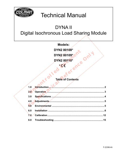
Technical Manual<br />
<strong>DYNA</strong> <strong>II</strong><br />
<strong>Digital</strong> <strong>Isochronous</strong> <strong>Load</strong> <strong>Sharing</strong> Module<br />
Models:<br />
DYN2 80108*<br />
DYN2 80109*<br />
DYN2 80110*<br />
*<br />
Table of Contents<br />
1.0 Introduction.....................................................................................2<br />
2.0 Operation ........................................................................................3<br />
3.0 Specifications .................................................................................4<br />
Uncontrolled Document<br />
4.0 Adjustments....................................................................................5<br />
For Historical Reference Only<br />
5.0 Environmental ................................................................................5<br />
6.0 Installation ......................................................................................6<br />
7.0 Calibration.....................................................................................12<br />
8.0 Troubleshooting ...........................................................................15<br />
F-22396-4A
1.0 INTRODUCTION<br />
1.1 FUNCTION<br />
1.5 SAFETY<br />
The Barber-Colman <strong>DYNA</strong> <strong>II</strong> <strong>Digital</strong> <strong>Isochronous</strong> <strong>Load</strong><br />
<strong>Sharing</strong> Control operates with any of the <strong>DYNA</strong> allelectric<br />
precision governors. This combination permits<br />
proportional division of a common load between multi<strong>pl</strong>e<br />
engine-generator sets while maintaining a fixed frequency<br />
on an isolated bus.<br />
1.2 MULTI-GEN SET CAPABILITY<br />
The ILS Control will enable a common load to be proportionately<br />
shared among any number of engine generators<br />
in a system. The generators need not have the same<br />
kilowatt ratings. All generators in the system will assume<br />
equal percentages of their full load capacity.<br />
1.3 THREE BASIC MODELS<br />
Three models of the isochronous load sharing control<br />
are available.<br />
1. 115 to 230 Volts AC, 50 to 60 Hz — DYN2-80108.<br />
2. 240 to 480 Volts AC, 50 to 60 Hz — DYN2-80109.<br />
3. 240 to 480 Volts AC, 400 Hz — DYN2-80110.<br />
1.4 LOAD PULSE<br />
The load pulse feature senses generator load changes<br />
and signals the governor to increase or decrease engine<br />
fuel before there is an actual change in engine speed.<br />
Depending upon the engine being controlled, offspeed<br />
transient performance may be improved by up to 25-30<br />
percent. The amount of load pulse is adjustable.<br />
The module’s cover protects all adjustments and covers<br />
the terminal strip when in <strong>pl</strong>ace.<br />
1.6 DROOP MODE<br />
In addition to isochronous operation, a droop mode may<br />
be selected for ap<strong>pl</strong>ications when generators are paralleled<br />
with an infinite bus.* The maximum amount of<br />
droop is adjustable from 0 to 10 percent at full load.<br />
1.7 HIGH RELIABILITY<br />
The <strong>DYNA</strong> <strong>II</strong> <strong>Digital</strong> ILS Module em<strong>pl</strong>oys all solid state<br />
circuitry for high reliability. After assembly, each unit is<br />
subjected to thorough functional testing under operating<br />
conditions.<br />
1.8 ENCLOSURE<br />
Uncontrolled Document<br />
The <strong>Digital</strong> ILS Module is one compact assembly. No<br />
separate burden resistor box is required. The module<br />
cover is a sturdy non-conductive <strong>pl</strong>astic that is secured<br />
to the module by two knurled nuts. The module is<br />
designed for behind-the-panel mounting.<br />
*Infinite bus is defined as a bus so large that an engine<br />
being <strong>pl</strong>aced in parallel with this bus will not be able to<br />
affect the bus frequency.<br />
For Historical Reference Only<br />
2
2.0 PARALLEL OPERATION USING DIGITAL ILS MODULE<br />
2.1 ISOCHRONOUS CONFIGURATION<br />
2.3 LOAD PULSE<br />
The object of isochronous load sensing is to proportionally<br />
divide a common load between two or more engine<br />
generator sets while maintaining a fixed frequency on an<br />
isolated bus. Each DYN2 <strong>Digital</strong> ILS Control compares<br />
the load of its generator unit with the load ap<strong>pl</strong>ied to all<br />
other units in operation, through the paralleling lines, and<br />
either decreases or increases the engine fuel to maintain<br />
its proportional share of the total load.<br />
Figure 4, in the Installation section, shows a typical<br />
DYN2 <strong>Digital</strong> ILS wiring diagram for parallel isochronous<br />
operation of two generators.<br />
2.2 DROOP CONFIGURATION<br />
The droop configuration is necessary to limit the load<br />
carried by the engine generator sets when paralleled<br />
with an infinite bus. The infinite bus frequency is fixed;<br />
therefore, operating isochronously will either overload<br />
the engine/ generator or cause shutdown on reverse<br />
current, depending upon whether the reference speed<br />
for the engine/generator is below or above the bus<br />
frequency.<br />
All engine/generators should be set to the same droop<br />
when connected to the bus. Once the engine/generators<br />
are paralleled in droop on an infinite bus, load is picked<br />
up by increasing the fuel on each engine/generator.<br />
The droop mode is obtained when terminal 11 is connected<br />
to terminal 12. The amount of droop is adjustable<br />
over the range of 0 to 10% by setting the “droop”<br />
potentiometer.<br />
The load pulse feature senses generator load changes<br />
and signals the governor to increase or decrease engine<br />
fuel before there is an actual change in engine speed.<br />
Depending upon the engine being controlled, offspeed<br />
transient performance may be improved by up to 25-30%.<br />
The amount of load pulse is adjustable.<br />
2.4 THE ILS MODULE CAN PROVIDE GOVERNOR<br />
CONTROL IN FOUR MODES<br />
• Single unit isochronous<br />
• Single unit droop<br />
• Parallel unit isochronous<br />
• Parallel unit droop<br />
Uncontrolled Document<br />
For Historical Reference Only<br />
3
3.0 SPECIFICATIONS<br />
AC Voltage Inputs<br />
Model with Line to Line Voltage of 115 to 230 ±20% Vac<br />
Input (50 or 60Hz ±5%): <strong>Digital</strong> ILS Module — Part No.<br />
DYN2 80108.<br />
Model with Line to Line Voltage of 230 to 480 ±20% Vac<br />
Input (50 or 60Hz ±5%): <strong>Digital</strong> ILS Module — Part No.<br />
DYN2 80109.<br />
<strong>Load</strong> <strong>Sharing</strong> Setability (Accuracy)<br />
Adjustable to ±0.5% between sets of equal size at full<br />
load.<br />
Outputs (Dependent on <strong>Load</strong> Gain Adjustment)<br />
Test Jacks: TP1 to TP2 — 6.0 Vdc typical at full load.<br />
Paralleling Line: 3.0 Vdc typical at full load.<br />
Model with Line to Line Voltage of 230 to 480 ±20% Vac<br />
Input (400 Hz ±5%): <strong>Digital</strong> ILS Module — Part No.<br />
DYN2 80110.<br />
DC Voltage Input 9 to 30 Vdc.<br />
Current Input 3 phase.<br />
2.5 to 5.0 Amperes per phase at maximum generator<br />
load.<br />
0.32 VA burden per phase on each current transformer<br />
at 2.5 Amperes.<br />
1.25 VA burden per phase on each current transformer<br />
at 5.0 Amperes.<br />
Speed Correcting Signal: Compatible with standard<br />
DYN1 controllers.<br />
Reverse Power Relay Contacts: Normally closed<br />
10 Amperes resistive at 115 Vac (UL Approved)<br />
5 Amperes resistive at 230 Vac (UL Approved)<br />
Forward Power Relay Contacts: Normally open<br />
10 Amperes resistive at 115 Vac (UL Approved)<br />
5 Amperes resistive at 230 Vac (UL Approved)<br />
Uncontrolled Document<br />
Forward Power Monitor: 0 to 5 Vdc or 0 to 5 mAdc<br />
analog signal with full scale accuracy of 1%. Minimum<br />
meter movement of 10,000 ohms.<br />
For Historical Reference Only<br />
4
4.0 ADJUSTMENTS<br />
Current Transformer Calibration<br />
“CT Cal”— calibration to correct for variation in current<br />
obtained from the current transformers. Clockwise increases<br />
the output signal obtained at the test points.<br />
<strong>Load</strong> <strong>Sharing</strong> Gain<br />
“LS Gain”— test point signal — clockwise increases<br />
signal voltage at test points, TP1 to TP2. Clockwise will<br />
decrease percentage of load carried by the generator.<br />
Exam<strong>pl</strong>es:<br />
l<br />
l<br />
Trip time with a reverse power of 5% over setpoint is<br />
approximately 20 seconds.<br />
Trip time with a reverse power of 40% over setpoint is<br />
approximately 5 seconds.<br />
Forward Power Relay Trip Points<br />
Droop 0 to 10% — clockwise increases droop setting.<br />
<strong>Load</strong> Pulse Clockwise increases load pulse output.<br />
Reverse Power Relay Trip Point<br />
“RPLVL” — clockwise increases trip point. Trip point is<br />
adjustable with a range of 0 to 40% of full load. The trip<br />
point has an inverse time constant which decreases<br />
relay trip time on larger reverse power levels.<br />
Ambient Operating Temperature<br />
-40° to 85°C (-40° to 185° F).<br />
Enclosure<br />
The <strong>Digital</strong> ILS Module is one compact assembly. The<br />
module cover is a sturdy nonconductive <strong>pl</strong>astic that is<br />
secured to the module by two knurled nuts. The module<br />
is designed for behind-the panel mounting.<br />
5.0 ENVIRONMENTAL<br />
Uncontrolled Document<br />
On Point: “FP On” — clockwise to increase, independent<br />
of “Off” point, adjustable with a range of 20 to 120% of<br />
full load.<br />
Off Point: “FP Off” — clockwise to increase, independent<br />
of “On” point, adjustable with a range of 10 to 100% of<br />
full load.<br />
Forward Power Monitor Gain<br />
“PM Gain” — clockwise to increase analog output<br />
signal, adjustable range of 5.0 Vdc or to 5 mAdc minimum<br />
at full load.<br />
Shock<br />
Withstands 15 G’s in each of three mutually perpendicular<br />
axes.<br />
Humidity<br />
Will operate properly through condensing conditions.<br />
For Historical Reference Only<br />
Manual F-22396 A.<br />
Mounting Attitude at any position.<br />
Vibration<br />
Withstands the following vibration without failure or degraded<br />
performance: 0.06 inch double am<strong>pl</strong>itude at 5 to<br />
18 Hz; 1 G at 18 to 30 Hz; 0.02 inch double am<strong>pl</strong>itude at<br />
30 to 38 Hz; 2.5 G’s at 48 to 70 Hz.<br />
Typical Wiring Diagram<br />
Bulletin 16H,16J,16K,16L, 16N, 16O, 16P, 16Q, 16R,<br />
16S, 16T, 16U, 16V (for ).<br />
Weight<br />
1.25 Kg (2.75 Ibs.).<br />
5
6.0 INSTALLATION<br />
6.1 INTRODUCTION<br />
6.5 DROOP ISOCHRONOUS SWITCH<br />
This section provides general instructions for installing the<br />
<strong>DYNA</strong> <strong>II</strong> <strong>Digital</strong> ILS Modules. Power requirements, environmental<br />
precautions and location suggestions are included.<br />
6.2 DC POWER REQUIREMENTS<br />
The <strong>Digital</strong> ILS Module receives its DC power from the <strong>DYNA</strong><br />
control box and a separate 9.0 to 30.0 Vdc voltage connected<br />
to terminal 24. This voltage can be the same DC power source<br />
as that used for the <strong>DYNA</strong> governor if the DC voltage is +12 or<br />
+24 Vdc.<br />
6.3 ENVIRONMENTAL PRECAUTIONS<br />
The <strong>Digital</strong> ILS Module is designed to operate properly over the<br />
ambient temperature range of -40° to 185°F (-40° to 85°C).<br />
The unit can be mounted in any position. When mounting the<br />
<strong>Digital</strong> ILS Module, consider the following: adequate space for<br />
ventilation, proximity to other equipment, servicing or repairs<br />
and environmental conditions.<br />
6.4 WIRING THE DIGITAL ILS MODULE<br />
Wiring diagrams, Figures 4 and 4A, provide typical external<br />
connections for the <strong>Digital</strong> ILS Module. Make sure the wiring for<br />
the unit is installed properly and that all shields are connected<br />
as shown in the typical wiring diagram or as shown in the<br />
ap<strong>pl</strong>ication bulletin.<br />
NOTE<br />
For certifications, all shield connections are to be<br />
terminated to the provided chassis terminals. (See Bulletin<br />
16V)<br />
NOTE<br />
If neither terminal 17 nor terminal 18 is wired externally,<br />
wire terminal 15 to terminal 18.<br />
CAUTION<br />
Do not run shielded lines in same conduit as heavy<br />
current carrying cables.<br />
This switch (see Figures 4 and 4A) is not required if the <strong>Digital</strong><br />
ILS will only be used in the <strong>Isochronous</strong> mode of operation.<br />
6.6 SIGNAL FLOW BACK DIAGRAM<br />
Figure 3 shows the basic signal flow paths between the<br />
different sections of the <strong>Digital</strong> ILS Module.<br />
6.7 WIRING OF PHASE VOLTAGE AND PHASE<br />
CURRENT<br />
1. Proper phase and polarity must be maintained.<br />
2. Phase voltages for A, B and C are obtained from the<br />
generator side of the circuit breaker and connected to the<br />
appropriate ILS terminals 1, 2 and 3.<br />
NOTE<br />
If the generator output voltage is higher than the input<br />
voltages of the ILS being installed, potential transformers<br />
must be used to step the voltage down to the appropriate<br />
values. (See notes 2 and 5 on Figure 4 for the current and<br />
voltage transformer VA ratings.)<br />
CAUTION<br />
Under-frequency protection should be provided for the<br />
generator if engine can be operated in an idle mode.<br />
6.8 TEST EQUIPMENT (TYPICAL)<br />
Type Model Characteristics<br />
Volt-Ohm-Meter Tri<strong>pl</strong>ett 310 C 20,000 ohms/volt<br />
or equivalent ±3% accuracy<br />
Uncontrolled Document<br />
For Historical Reference Only<br />
Figure 1.<br />
Dimensions<br />
(for reference only)<br />
6
TPB<br />
TPA<br />
RPLVL FP<br />
TPC OFF<br />
FP<br />
ON<br />
LOAD<br />
PULSE<br />
LS CT<br />
DROOP GAIN CAL<br />
Figure 2.<br />
TPN TP2 TP1<br />
PM<br />
GAIN<br />
Uncontrolled Document<br />
For Historical Reference Only<br />
Figure 3. Block Diagram of <strong>DYNA</strong> <strong>II</strong> <strong>Digital</strong> <strong>Isochronous</strong> <strong>Load</strong> <strong>Sharing</strong> Module<br />
7
6.9 DIGITAL ISOCHRONOUS LOAD<br />
SHARING CONTROL<br />
NOTES<br />
(Refer to Figure 4 on next page)<br />
The <strong>Digital</strong> <strong>Isochronous</strong> <strong>Load</strong> <strong>Sharing</strong> Control, DYN2 80108,<br />
DYN2 80109 or DYN2 80110 can be used with the <strong>DYNA</strong> 8000<br />
governor to provide control of an engine generator set by<br />
maintaining preset engine speed or proportional sharing of<br />
load between similar or dissimilar generators. Both droop and<br />
isochronous modes can be selected.<br />
Figure 4 illustrates the wiring of two engine generator sets<br />
having <strong>DYNA</strong> 8000 governors and <strong>Digital</strong> <strong>Isochronous</strong> <strong>Load</strong><br />
<strong>Sharing</strong> Controls. Additional engine generator sets can be<br />
paralleled by wiring them at the point designated, PARALLEL-<br />
ING LINES TO OTHER SYSTEMS.<br />
CAUTION<br />
It is recommended that an independent overspeed<br />
shutdown device be incorporated in every engine control<br />
system.<br />
1. If more than one engine is started using the same battery<br />
sup<strong>pl</strong>y, use separate battery sup<strong>pl</strong>y for each governor<br />
system. Twist power leads and use shielded leads as<br />
shown<br />
2. Select current transformers to provide 2.5 to 5.0 amps at<br />
full rated load. Current transformers require nominal 0.32<br />
VA/PHASE at 2.5 amps 1.25 VA/PHASE at 5.0 amps<br />
3. Observe current transformer polarity markings when connecting.<br />
4. Power switch current rating: 10 amps.<br />
5. Phasing of potential to Terminals 1, 2 and 3 is necessary<br />
to keep each signal in its correct phase relationship. If the<br />
generator voltage is not the same as the voltage range on<br />
Terminals 1, 2 and 3 of the <strong>Isochronous</strong> <strong>Load</strong> <strong>Sharing</strong><br />
Control, a step-down transformer is required. Correct<br />
phasing of the transformer leads is necessary. Step-down<br />
transformers require nominal 1 VA/PHASE<br />
6. Droop/<strong>Isochronous</strong> switch is not required if units are<br />
always operated in the <strong>Isochronous</strong> mode<br />
7. <strong>Digital</strong> ILS<br />
DYN2 80108 — 115/230 Vac input-50/60 Hz<br />
DYN2 80109 — 230/480 Vac input-50/60 Hz<br />
DYN2 80110 — 230/480 Vac input-400 Hz<br />
8. <strong>DYNA</strong> 8000 Controllers<br />
9. <strong>DYNA</strong> 8000, 8200, or 8400.<br />
Uncontrolled Document<br />
NOTE<br />
Barber-Colman believes that all information provided herein is<br />
correct and reliable and reserves the right to update at any<br />
time. Barber-Colman does not assume any responsibility for its<br />
use unless otherwise expressly undertaken<br />
For Historical Reference Only<br />
*Shielded Cable — should be purchased from BarberColman<br />
or customer should purchase a cable with a wrapped mylar<br />
supported aluminum foil shield with a drain wire.<br />
8
Figure 4. Typical Electrical Schematic<br />
<strong>DYNA</strong> 8000 Governor<br />
}<br />
AT<br />
GENERATOR<br />
NO. 1<br />
9<br />
8<br />
7<br />
6<br />
5<br />
4<br />
3<br />
2<br />
1<br />
20<br />
21<br />
22<br />
23<br />
‡ KW Meter not sup<strong>pl</strong>ied by Barber-Colman<br />
10<br />
12<br />
11<br />
13<br />
16<br />
14<br />
15<br />
19<br />
24<br />
18<br />
*<br />
22 AWG<br />
10<br />
12<br />
11<br />
13<br />
DROOP ISOCHRONOUS<br />
SWITCH (SEE NOTE 6)<br />
*<br />
+<br />
-<br />
11<br />
1<br />
2<br />
3<br />
6<br />
8<br />
7<br />
9<br />
10<br />
-<br />
+<br />
B<br />
CONNECT TO<br />
SYSTEM 1<br />
BATTERY<br />
B<br />
PARALLELING LINES<br />
TO OTHER SYSTEMS<br />
CONNECT TO<br />
SYSTEM 2<br />
BATTERY {<br />
AT X<br />
+ +<br />
TO LOAD<br />
22 AWG<br />
ALTERNATE WIRING WHEN THE DROOP/ISOCHRONOUS SWITCH IS REQUIRED<br />
DROOP<br />
*<br />
ISOCHRONOUS<br />
<strong>DYNA</strong> 8000<br />
PANEL<br />
MOUNTED<br />
CONTROL<br />
SEE NOTE 8<br />
UNIT NO. 1<br />
22 AWG<br />
SHIELDED<br />
PAIRS<br />
PARALLELING LINES<br />
TO OTHER SYSTEMS<br />
DROOP ISOCHRONOUS<br />
SWITCH (SEE NOTE 6)<br />
DROOP<br />
ISOCHRONOUS<br />
X<br />
-<br />
+<br />
22 AWG<br />
PAIRS<br />
+<br />
-<br />
*<br />
10<br />
12<br />
11<br />
13<br />
10<br />
12<br />
11<br />
13<br />
16<br />
14<br />
15<br />
17<br />
19<br />
24<br />
18<br />
9<br />
8<br />
7<br />
6<br />
5<br />
4<br />
3<br />
2<br />
1<br />
20<br />
GENERATOR<br />
NO. 2<br />
CABLE A<br />
4 5<br />
SEE NOTE 9<br />
<strong>DYNA</strong> 8000<br />
PANEL<br />
MOUNTED<br />
CONTROL<br />
SEE NOTE 8<br />
UNIT NO. 2<br />
4<br />
5<br />
10<br />
1<br />
2<br />
3<br />
6<br />
8<br />
7<br />
9<br />
11<br />
21<br />
22<br />
23<br />
NOTE<br />
See Bulletin 16V for proper<br />
wiring.<br />
GENERATOR<br />
NO. 1<br />
CIRCUIT<br />
BREAKER<br />
AUXILIARY<br />
CIRCUIT BREAKER<br />
CONTACT<br />
AUXILIARY<br />
CIRCUIT BREAKER<br />
CONTACT<br />
GENERATOR<br />
NO. 2<br />
CIRCUIT<br />
BREAKER<br />
<br />
<br />
<br />
<br />
<br />
<br />
REMOTE<br />
SPEED<br />
POTENTIOMETER 5K<br />
CW<br />
REMOTE<br />
SPEED<br />
POTENTIOMETER<br />
5K<br />
CW<br />
SYSTEM 1<br />
BATTERY<br />
SEE NOTE 1<br />
OFF<br />
#14<br />
TWISTED<br />
PAIR<br />
ON<br />
+4 VDC<br />
<br />
<br />
A<br />
B<br />
C<br />
18 AWG<br />
SEE NOTES 2 & 3<br />
18 AWG<br />
SEE NOTES 2 & 3<br />
18 AWG<br />
SEE NOTES 2 & 3<br />
SEE NOTES 5 & 7<br />
STEPDOWN<br />
POTENTIAL<br />
TRANSFORMER<br />
AS REQUIRED<br />
FORWARD<br />
POWER<br />
RELAY<br />
REVERSE<br />
POWER<br />
RELAY<br />
DIGITAL<br />
ISOCHRONOUS<br />
LOAD<br />
SHARING<br />
CONTROL<br />
UNIT<br />
NO. 1 17<br />
22 AWG<br />
SHIELDED<br />
TRIAD<br />
UNIT<br />
NO. 2<br />
N.O.<br />
N.C.<br />
18 AWG<br />
B A<br />
MAGNETIC<br />
PICKUP<br />
DYNT<br />
C<br />
SEE NOTES 2 & 3<br />
18 AWG<br />
SEE NOTES 2 & 3<br />
18 AWG<br />
POWER SWITCH<br />
SEE NOTE 4<br />
SEE NOTES 2 & 3<br />
14 AWG<br />
TWISTED<br />
PAIR<br />
22 AWG<br />
SHIELDED<br />
TRIAD<br />
OFF<br />
SYSTEM 2<br />
BATTERY<br />
SEE NOTE 1<br />
SEE NOTES 5 & 7<br />
STEPDOWN<br />
POTENTIAL<br />
TRANSFORMER<br />
AS REQUIRED<br />
FORWARD<br />
POWER<br />
RELAY<br />
REVERSE<br />
POWER<br />
RELAY<br />
22 AWG<br />
SHIELDED<br />
TRIAD<br />
B<br />
A<br />
<br />
<br />
<br />
ON<br />
18 AWG<br />
<br />
<br />
+ 4 VDC<br />
<br />
<br />
KW<br />
METER<br />
<br />
KW<br />
METER<br />
‡<br />
‡<br />
B<br />
A<br />
SYNC<br />
SYNC<br />
MAGNETIC<br />
PICKUP<br />
DYNT<br />
SEE<br />
NOTE 7<br />
N.O.<br />
N.C.<br />
SEE<br />
NOTE 7<br />
DIGITAL<br />
ISOCHRONOUS<br />
LOAD<br />
SHARING<br />
CONTROL<br />
Uncontrolled Document<br />
18 AWG<br />
22 AWG<br />
SHIELDED<br />
PAIRS<br />
For Historical Reference Only<br />
22 AWG<br />
SHIELDED<br />
PAIRS<br />
+9 to 30 Vdc<br />
<br />
TWISTED<br />
PAIR<br />
14 AWG.<br />
TWISTED<br />
PAIR<br />
14 AWG<br />
<br />
<br />
DYNC<br />
Actuator<br />
DYNC<br />
Actuator<br />
9
6.10 DIGITAL ISOCHRONOUS LOAD SHARING<br />
CONTROL<br />
The <strong>Digital</strong> <strong>Isochronous</strong> <strong>Load</strong> <strong>Sharing</strong> Control, DYN2 80108,<br />
DYN2 80109 or DYN2 80110 can be used with the <strong>DYNA</strong><br />
governor to provide control of an engine generator set by<br />
maintaining preset engine speed or proportional sharing of<br />
load between similar or dissimilar generators. Both droop and<br />
isochronous modes can be selected.<br />
Figure 4A illustrates the wiring of two engine generator sets<br />
having <strong>DYNA</strong> governors and <strong>Digital</strong> <strong>Isochronous</strong> <strong>Load</strong> <strong>Sharing</strong><br />
Controls. Additional engine generator sets can be paralleled by<br />
wiring them at the point designated, PARALLELING LINES TO<br />
OTHER SYSTEMS.<br />
NOTES<br />
(Refer to Figure 4A on next page.<br />
1. If more than one engine is started using the same battery<br />
sup<strong>pl</strong>y, use separate battery sup<strong>pl</strong>y for each governor<br />
system. Twist power leads and use shielded leads as<br />
shown.<br />
2. Select current transformers to provide 2.5 to 5.0 amps at full<br />
rated load. Current transformers require nominal 0.32 VA/<br />
PHASE at 2.5 amps 1.25 VA/PHASE at 5.0 amps<br />
3. Observe current transformer polarity markings when connecting.<br />
CAUTION<br />
It is recommended that an independent overspeed shutdown<br />
device be incorporated in every engine control<br />
system.<br />
4. Power switch current rating 10 amps.<br />
5. Phasing of potential to Terminals 1, 2 and 3 is necessary to<br />
keep each signal in its correct phase relationship If the<br />
generator voltage is not the same as the voltage range on<br />
Terminals 1, 2 and 3 of the <strong>Isochronous</strong> <strong>Load</strong> <strong>Sharing</strong><br />
Control, a step-down transformer is required. Correct phasing<br />
of the transformer leads is necessary. Step-down transformers<br />
require nominal 1 VA/ PHASE.<br />
6. Droop/lsochronous switch is not required if nits are always<br />
operated in the <strong>Isochronous</strong> mode.<br />
7. <strong>Digital</strong> ILS<br />
DYN2 80108 — 115/230 Vac input-50/60 Hz<br />
DYN2 80109 — 230/480 Vac input-50/60 Hz<br />
DYN2 80110 — 230/480 Vac input-400 Hz<br />
Uncontrolled Document<br />
8. <strong>DYNA</strong> Controllers: DYN1 10502, DYN1 10503, DYN1<br />
10504 or DYN1 10506<br />
9. <strong>DYNA</strong> Actuators: Plus 1 or Plus 4<br />
Plus 1 Units — DYNC 11000, DYNC 11001, DYNC 11002,<br />
DYNC 11004, DYNC 11005 or DYNC 11006<br />
Plus 4 Units — DYNC 14000<br />
NOTE<br />
Barber-Colman believes that all information provided herein is<br />
correct and reliable and reserves the right to update at any<br />
time. Barber-Colman does not assume any responsibility for its<br />
use unless otherwise expressly undertaken .<br />
For Historical Reference Only<br />
*Shielded Cable — should be purchased from Barber-Colman<br />
or customer should purchase a cable with a wrapped mylar<br />
supported aluminum foil shield with a drain wire.<br />
10
NOTE<br />
See Bulletin 16V for proper<br />
wiring.<br />
TO LOAD<br />
22 AWG CONNECT TO CONNECT TO<br />
22 AWG<br />
+ SYSTEM 1<br />
SYSTEM 2 +<br />
} BATTERY<br />
BATTERY {<br />
AT B<br />
AT X<br />
ALTERNATE WIRING WHEN THE DROOP/ISOCHRONOUS SWITCH IS REQUIRED<br />
GENERATOR<br />
NO. 1<br />
CIRCUIT<br />
BREAKER<br />
PARALLELING LINES<br />
TO OTHER SYSTEMS<br />
DROOP ISOCHRONOUS<br />
SWITCH (SEE NOTE 6)<br />
22 AWG<br />
SHIELDED<br />
PAIRS<br />
DROOP ISOCHRONOUS<br />
SWITCH (SEE NOTE 6)<br />
10<br />
10<br />
*<br />
AUXILIARY<br />
CIRCUIT<br />
BREAKER<br />
CONTACT<br />
12<br />
*<br />
DROOP<br />
DROOP<br />
*<br />
12<br />
AUXILIARY<br />
CIRCUIT BREAKER<br />
CONTACT<br />
GENERATOR<br />
NO. 2<br />
CIRCUIT<br />
BREAKER<br />
11<br />
ISOCHRONOUS<br />
11<br />
22 AWG<br />
SHIELDED<br />
PAIRS<br />
ISOCHRONOUS<br />
13<br />
10<br />
12<br />
11<br />
9<br />
8<br />
7<br />
6<br />
5<br />
C<br />
18 AWG<br />
SEE NOTES 2 & 3<br />
B<br />
18 AWG<br />
SEE NOTES 2 & 3<br />
A<br />
18 AWG<br />
SEE NOTES 2 & 3<br />
4<br />
3<br />
2<br />
1<br />
STEPDOWN<br />
POTENTIAL<br />
TRANSFORMER<br />
AS REQUIRED<br />
17<br />
UNIT<br />
NO. 2<br />
GENERATOR<br />
NO. 2<br />
13<br />
PARALLELING LINES<br />
TO OTHER SYSTEMS<br />
C<br />
16<br />
9<br />
-<br />
18 AWG<br />
10<br />
24<br />
SEE NOTES 2 & 3<br />
22 AWG<br />
SHIELDED<br />
TRIAD<br />
8<br />
KW<br />
METER<br />
‡<br />
SYNC<br />
SEE NOTES 5 & 7<br />
13<br />
19<br />
20<br />
21<br />
FORWARD<br />
POWER<br />
RELAY<br />
22<br />
23<br />
REVERSE<br />
POWER<br />
RELAY<br />
12<br />
N.O.<br />
18 AWG<br />
N.C.<br />
-<br />
B<br />
*<br />
7<br />
SEE<br />
NOTE 7<br />
11<br />
DIGITAL<br />
ISOCHRONOUS<br />
LOAD<br />
SHARING<br />
CONTROL<br />
-<br />
SEE NOTES 2 & 3<br />
6<br />
REMOTE<br />
SPEED<br />
POTENTIOMETER<br />
18 AWG<br />
A<br />
5K<br />
CW<br />
-<br />
REMOTE<br />
SPEED<br />
POTENTIOMETER<br />
-<br />
5K<br />
CW<br />
22 AWG<br />
SHIELDED<br />
PAIR<br />
5<br />
POWER SWITCH<br />
SEE NOTE 4<br />
SEE NOTES 2 & 3<br />
11<br />
14 AWG<br />
TWISTED<br />
PAIR<br />
14<br />
15<br />
4<br />
SYSTEM 1<br />
BATTERY<br />
SEE NOTE 1<br />
3<br />
OFF<br />
14 AWG<br />
TWISTED<br />
PAIR<br />
SEE NOTES 5 & 7<br />
OFF<br />
+<br />
SYSTEM 2<br />
BATTERY<br />
SEE NOTE 1<br />
+<br />
ON<br />
X<br />
B<br />
ON<br />
-<br />
2<br />
SEE<br />
NOTE 7<br />
+<br />
13<br />
13<br />
+<br />
1<br />
18 AWG<br />
13<br />
12<br />
<strong>DYNA</strong>1<br />
PANEL<br />
MOUNTED<br />
CONTROL<br />
<strong>DYNA</strong>1<br />
PANEL<br />
MOUNTED<br />
CONTROL<br />
12<br />
9<br />
BLACK<br />
DIGITAL<br />
ISOCHRONOUS<br />
LOAD<br />
SHARING<br />
CONTROL<br />
18<br />
Uncontrolled Document<br />
STEPDOWN<br />
POTENTIAL<br />
TRANSFORMER<br />
AS REQUIRED<br />
UNIT<br />
NO. 2<br />
UNIT<br />
NO.1<br />
+4 VDC<br />
+4 VDC<br />
16<br />
14<br />
15<br />
SEE<br />
NOTE 8<br />
SEE<br />
NOTE 8<br />
8<br />
7<br />
22 AWG<br />
SHIELDED<br />
PAIRS<br />
22 AWG<br />
SHIELDED<br />
PAIRS<br />
For Historical Reference Only<br />
22 AWG<br />
SHIELDED<br />
TRIAD<br />
18 AWG<br />
6<br />
6<br />
UNIT<br />
NO. 1 17<br />
8<br />
7<br />
9<br />
10<br />
19<br />
20<br />
KW<br />
METER<br />
N.O.<br />
11<br />
1<br />
2<br />
3<br />
4<br />
5<br />
10<br />
11 1 2 3 4 5<br />
21<br />
FORWARD<br />
POWER<br />
RELAY<br />
GENERATOR<br />
NO. 1<br />
‡<br />
+9 to 30 Vdc +9 to 30 Vdc<br />
1 2 3 4 5<br />
5 4 3 2 1<br />
3<br />
3<br />
24<br />
22<br />
N.C.<br />
B<br />
A<br />
B A<br />
23<br />
REVERSE<br />
POWER<br />
RELAY<br />
BLACK<br />
RED<br />
BLACK<br />
WHITE<br />
RED<br />
RED<br />
RED<br />
WHITE<br />
BLACK<br />
SYNC<br />
18<br />
A B C D E<br />
A<br />
B<br />
C<br />
D<br />
E<br />
MAGNETIC<br />
PICKUP<br />
DYNT<br />
+ -<br />
+<br />
+<br />
MAGNETIC<br />
PICKUP<br />
DYNT<br />
‡ KW Meter not sup<strong>pl</strong>ied by Barber-Colman<br />
SEE NOTE 9<br />
Figure 4A. Typical Electrical Schematic<br />
<strong>DYNA</strong><br />
ACTUATOR<br />
<strong>DYNA</strong><br />
ACTUATOR
7.0 CALIBRATION INSTRUCTIONS FOR DIGITAL ILS<br />
7.1 INSTALLATION CHECKOUT<br />
Following com<strong>pl</strong>etion of system wiring and before starting the<br />
engine/generator, perform the checkout procedure to assist in<br />
verifying that the ILS unit is operational. These checks provide<br />
an indication of the unit’s operating capability.<br />
7.1.1 Remove the ILS module cover.<br />
7.1.2 Visual inspection.<br />
RPM for generating the desired generator output frequency.<br />
c. Calibrate the <strong>DYNA</strong> controller per the calibration and adjustment<br />
sheet for the controller.<br />
d. Once engine/generator is running stable, proceed to step<br />
7.1.7, ILS voltage and current phasing check.<br />
7.1.7 ILS voltage and current phasing check.<br />
a. Check all wiring for loose connections or broken wires.<br />
b. Check wiring to verify it agrees with the system wiring<br />
diagram.<br />
c. Repair or correct wiring before starting engine/ generator.<br />
7.1.3 ILS initial potentiometer settings.<br />
a. Set “LS Gain” potentiometer fully clockwise.<br />
b. Set “Droop” potentiometer fully counterclockwise.*<br />
c. Set forward power on, “FP On”, potentiometer fully CW.<br />
d. Set forward power off, “FP Off”, potentiometer fully CW.<br />
e. Set reverse power, “RPLVL”, potentiometer fully CW.<br />
f. Set “<strong>Load</strong> Pulse” potentiometer fully CCW.<br />
NOTE<br />
“Balance” potentiometer is factory set.<br />
* If the unit must be set up against an infinite bus, then set<br />
“Droop” potentiometer at mid-range for a starting point.<br />
7.1.4 If “Remote Speed” potentiometer is used, set<br />
it to mid-range.<br />
(The Barber-Colman potentiometer is a 10-turn unit.)<br />
7.1.5 Check the <strong>DYNA</strong> controller and, if necessary,<br />
set potentiometer as called out on the calibration<br />
and adjustments sheet for the <strong>DYNA</strong> I<br />
controller.<br />
CAUTION<br />
Current transformers must be connected to burden resistors.<br />
Do not operate engine/generator when any leads are removed<br />
from terminals 4, 5, 6, 7, 8 or 9 of the ILS module. Current<br />
transformers can develop dangerously high voltages when<br />
they are operated into an open circuit.<br />
7.1.6 Start the engine.<br />
a. If the actuator does not allow the fuel system to open far<br />
enough to allow engine to start, the “Speed” potentiometer<br />
will have to be adjusted clockwise to increase the<br />
speed setting.<br />
Uncontrolled Document<br />
a. Start engine/generator and load unit to as near full load as<br />
possible with a unity power factor load. Keep load constant<br />
and balanced.<br />
b. Connect DC voltmeter to TP1 and TP2 test jacks. See<br />
Figure 2 in the Installation section. The red jack is <strong>pl</strong>us and<br />
the black jack is minus. The positive lead of the voltmeter<br />
goes into the red jack.<br />
Adjust the C.T. CAL potentiometer to achieve 7.5 Vdc at<br />
the test points. Clockwise increases test point voltage;<br />
counterclockwise decreases test point voltage.<br />
CAUTION<br />
Current transformers must be connected to burden<br />
resistors. Do not operate engine/generator when any<br />
leads are removed from terminals 4, 5, 6, 7, 8 or 9 of<br />
the ILS module. Current transformers can develop<br />
dangerously high voltages when they are operated<br />
into an open circuit.<br />
c. Check for correct phasing of the voltage and current inputs<br />
to the ILS module by <strong>pl</strong>acing a jumper between test points<br />
TPA and TPN (phase A). The voltage at test jacks TP1 and<br />
TP2 should drop by approximately 1/3. Remove jumper<br />
from between test points TPA and TPN.<br />
Repeat procedure for test points TPB and TPN (phase B)<br />
and test points TPC and TPN (phase C). Each time the<br />
voltage should drop by 1/3. If the above conditions are not<br />
obtained, proceed with the next step to establish the<br />
correct phase relationship for the potential and current<br />
transformer connections. If the phase wiring is correct,<br />
proceed to step 7.1 .8.<br />
For Historical Reference Only<br />
b. Adjust the <strong>DYNA</strong> controller’s internal “Speed” potentiometer<br />
until the engine/generator is operating at the correct 12<br />
NOTE<br />
Improper wiring of the three-phase current and voltage<br />
inputs causes most parallel load sharing difficulties.<br />
The voltage of one phase is often wired with the<br />
current signal of another phase or transformers are<br />
wired in backwards so that the two signals oppose<br />
rather than add to each other.<br />
d. Stop the engine. Recheck the wiring. Make certain all CTs<br />
are phased identically and that the voltage at terminal 1<br />
comes from the same phase as the CT connected to<br />
terminals 4 and 5. Terminal 2’s voltage connection should<br />
be from the same phase as the CT connected to terminals<br />
6 and 7, and terminal 3’s voltage should be from the same<br />
phase as the CT connected to terminals 8 and 9. Correct
any mistakes and repeat steps A through C, recording the<br />
voltage at the test points for each step.<br />
e. Stop the engine. If the test point voltage is negative, but still<br />
drops by 1/3 when the jumper is ap<strong>pl</strong>ied to each CT<br />
connection, then all CTs are phased backwards. Terminals<br />
4 & 5, 6 & 7 and 8 & 9 should be swapped. If the jumper<br />
causes any test point voltage to increase, then it is likely<br />
that phase is backwards.<br />
f. To determine if all CTs are functioning, the voltage across<br />
the ILS’s burden resistors can be read. This voltage should<br />
be .05 ohms x secondary current. Check that the CT<br />
scaling is correct for your generator.<br />
g. When proper power measurement is achieved, proceed to<br />
step 7.1.8.<br />
7.1.8 CT Cal adjustment.<br />
a. Start the engine and load the generator to 100% load. Then<br />
adjust the I LS module “CT Cal” potentiometer for 7.5 Vdc<br />
at TP1 and TP2. The following table can be used for setting<br />
TP1 and TP2 if 100% load cannot be obtained.<br />
% <strong>Load</strong> TP1 to TP2 DC Voltage<br />
80 6.00<br />
50 3.50<br />
20 1.50<br />
b. Do not adjust the CT Cal potentiometer again. It may be<br />
desirable to ap<strong>pl</strong>y an adhesive such as RTV to make<br />
further adjustment more difficult.<br />
7.1.9 LS Gain adjustment.<br />
a. Next, with the same load ap<strong>pl</strong>ied, turn the “LS Gain”<br />
potentiometer CCW until the test point voltage drops to<br />
8/10 of its previous value.<br />
b. At unity power factor measure the governor KW output or<br />
calculate it based on voltage and current readings.<br />
7.1.10 PM Gain adjustment.<br />
Uncontrolled Document<br />
b. The power monitor output has a range of 0-5 volts DC or<br />
0-5 mA for 100% load and the test points at 7.5 volts. Adjust<br />
the “PM Gain” potentiometer to provide the correct KW<br />
reading on your meter. Lock the “PM Gain” potentiometer<br />
with adhesive.<br />
c. Now continue with the other adjustments as necessary in<br />
steps 7.1.11, 7.1.12, 7.1.13 and 7.1.14.<br />
7.1.11 ILS “Droop” potentiometer adjustment.<br />
a. Turning the “Droop” potentiometer clockwise increases<br />
the percentage of droop. The “Droop” potentiometer sets<br />
the amount of speed regulation for the prime mover. The<br />
“Droop” potentiometer biases the wheatstone bridge in a<br />
direction to cause the speed to decrease with an increase<br />
in load. Percent of droop is the difference in engine speed<br />
at no load with respect to engine speed at full load expressed<br />
as a percentage. The ratio of full load capacity to<br />
actual load must be taken into consideration when the load<br />
does not have a unit power factor. To set droop, proceed<br />
with the following steps.<br />
b. Set Droop/<strong>Isochronous</strong> switch to droop position. If switch<br />
is not used, make sure ILS terminal 11 is connected to<br />
terminal 12.<br />
c. Set ILS “LS Gain” potentiometer to obtain 6V at TP1 and<br />
TP2 at full load. This voltage TP1 and TP2 must be set to<br />
the same value on all engines in the same system.<br />
NOTE<br />
If stability problems are evident during paralleling, reduce<br />
the voltage at the TP1 and TP2 by turning the LS<br />
Gain CCW. This reduction must be done on all ILS<br />
modules. All test point voltages must be equal at full load.<br />
d. Set “Droop” potentiometer to provide desired percentage<br />
of droop.<br />
e. Operate engine/generator at correct frequency of 50 or 60<br />
Hz no load and record Hz reading. This is frequency F1.<br />
f. <strong>Load</strong> engine/generator to full load and record Hz reading.<br />
This is frequency F2.<br />
For Historical Reference Only<br />
a. The ILS current transformer burden resistors are .05 ohms.<br />
Phase currents can be determined by measuring the<br />
voltage across the burden resistors, calculating the current<br />
transformer current,<br />
Vburden = CT current<br />
.05<br />
and scaling upward by the current transformer step down<br />
ratio.<br />
g. Calculate droop as shown below:<br />
% Droop = F1 - F2 x 100<br />
F2<br />
h. The above procedure may have to be repeated several<br />
times to obtain the desired percentage of droop.<br />
7.1.12 ILS “<strong>Load</strong> Pulse” potentiometer adjustment.<br />
KW can be calculated with the following equation:<br />
KW = 1.732 VLL (IA + IB + IC )<br />
3000<br />
NOTE<br />
If “<strong>Load</strong> Pulse” function is not being used, the “<strong>Load</strong><br />
Pulse” potentiometer must be set fully counterclockwise.<br />
a. load pulse sensor provides a pulse output to the am<strong>pl</strong>ifier<br />
when a step change in load on the generator occurs.<br />
13
. The “<strong>Load</strong> Pulse” adjustment should be set to provide the<br />
minimum pulse necessary to meet the required transient<br />
response of the system.<br />
c. Set “<strong>Load</strong> Pulse” potentiometer fully counterclockwise.<br />
d. If a recording of transient response is necessary, connect<br />
recorder to engine/generator under test.<br />
7.1.14 Reverse power level adjustment (RPLVL).<br />
a. The reverse power relay trip point can be approximately set<br />
without starting the engine. Its range of adjustment is 0%<br />
to 40% of generator maximum load with 40% being fully<br />
clockwise.<br />
e. Ap<strong>pl</strong>y and reject load per requirement.<br />
f. Increase the “<strong>Load</strong> Pulse” potentiometer and repeat step<br />
e until the offspeed transients meet the limits specified.<br />
7.1.13 Forward power on and off point adjustments<br />
(FP On and FP Off).<br />
a. The forward power on and off points can be approximately<br />
set without starting the engine. The off point must always<br />
be lower than the on point, and if having off and on points<br />
close together is desired, proceed to step b.<br />
If no relay closure is desired, set both adjustments fully CW.<br />
b. Turn the Forward Power On potentiometer fully CW.<br />
c. Turn the Forward Power Off potentiometer fully CCW.<br />
d. Start the engine and load it to the desired forward power on<br />
point. Slowly turn the Forward Power On potentiometer<br />
CCW until the forward power relay closes. The Forward<br />
Power On potentiometer is now set.<br />
e. Reduce generator loading to the desired forward power off<br />
point. Slowly turn the Forward Power Off potentiometer<br />
CW until the forward power relay opens again. The Forward<br />
Power Off potentiometer is set. It may be desirable to<br />
lock both settings with an adhesive to prevent further<br />
adjustment.<br />
Uncontrolled Document<br />
b. If more precise adjustment is needed, the generator can<br />
be loaded to the reverse power level desired and the RPL<br />
potentiometer slowly turned CCW until the reverse power<br />
relay opens.<br />
Reverse power level will have to be monitored at the test<br />
points. The power monitor output does not indicate reverse<br />
power.<br />
c. If the generator cannot be loaded into a reverse power<br />
condition, simulated reverse power can be used for calibration<br />
by reversing the CT polarities. This can be done by<br />
reversing the CT leads at terminals 4 & 5, 6 & 7 and 8 & 9.<br />
<strong>Load</strong> the generator to the desired reverse power level but<br />
in forward power. Slowly turn the RPL potentiometer CCW<br />
until the reverse power relay opens. It may be wise to lock<br />
this adjustment also. Stop the engine and be sure to<br />
correct terminals 4 & 5, 6 & 7 and 8 & 9.<br />
For Historical Reference Only<br />
14
8.0 TROUBLESHOOTING FOR <strong>DYNA</strong> <strong>II</strong> DIGITAL ILS<br />
All voltage measurements are made with respect to battery negative on the controller, unless otherwise noted.<br />
Evidence of<br />
Failure<br />
I. Engine operating<br />
above<br />
desired rpm and<br />
adjusting<br />
Remote Speed<br />
potentiometer<br />
does not bring<br />
unit back to<br />
operating speed.<br />
<strong>II</strong>. Engine low in<br />
rpm and<br />
adjusting<br />
Remote Speed<br />
potentiometer<br />
does not bring<br />
unit back to<br />
operating speed.<br />
Possible Causes<br />
1. Lead between DYN1 controller and<br />
terminal 13 on ILS is open or not<br />
connected.<br />
2. Lead between terminal 17 of ILS<br />
and the Remote Speed potentiometer<br />
is open or not connected.<br />
3. Lead between DYN1 controller and<br />
terminal 14 of ILS is open or not<br />
connected.<br />
4. Lead between terminal 13 of ILS<br />
and the CCW end of Remote<br />
Speed potentiometer open or not<br />
connected.<br />
5. Faulty Remote Speed potentiometer.<br />
(Potentiometer open internally<br />
at CCW end.)<br />
1. Lead to terminal 14 of ILS shorted<br />
to pin 13 of ILS.<br />
2. Lead between DYN1 controller and<br />
terminal 15 on ILS is open or not<br />
connected.<br />
Means of Detection<br />
1. Measure lead with ohmmeter<br />
for continuity.<br />
1. Measure lead with ohmmeter<br />
for continuity.<br />
1. Measure lead with ohmmeter<br />
for continuity.<br />
1. Measure lead with ohmmeter<br />
for continuity.<br />
2. Measure DC voltage between<br />
terminal 13 of ILS and the CW<br />
end of Remote Speed potentiometer.<br />
(CW end is positive.)<br />
This should be +4.0V ±0.5V.<br />
1. Remove lead from one end of<br />
Remote Speed potentiometer,<br />
then measure potentiometer<br />
with ohmmeter for continuity<br />
between CW and CCW end.<br />
Measure approximately 5000<br />
ohms. If continuity is not<br />
achieved (measures open<br />
circuit), potentiometer is faulty.<br />
Uncontrolled Document<br />
1. Using an ohmmeter, measure<br />
for a short circuit between<br />
terminals 13 and 14 on ILS.<br />
For Historical Reference Only<br />
1. Measure lead with ohmmeter<br />
for continuity.<br />
2. Measure DC voltage between<br />
terminals 13 and 15 of ILS.<br />
(Terminal 15 is positive.) This<br />
should be +4.0V ±0.5V.<br />
Corrective<br />
Action<br />
1. Change or correct<br />
wiring.<br />
1. Change or correct<br />
wiring.<br />
1. Change or correct<br />
wiring.<br />
1. Change or correct<br />
wiring.<br />
1. Re<strong>pl</strong>ace<br />
potentiometer.<br />
1. Correct wiring.<br />
1. Change or correct<br />
wiring.<br />
3. Faulty Remote Speed potentiometer.<br />
(Potentiometer open internally<br />
at CW end.)<br />
1. Remove lead from one end of<br />
Remote Speed potentiometer.<br />
2. Measure potentiometer with<br />
ohmmeter for continuity<br />
between CW and CCW end.<br />
1. Re<strong>pl</strong>ace<br />
potentiometer.<br />
15
All voltage measurements are made with respect to battery negative on the controller, unless otherwise noted.<br />
Evidence of<br />
Failure<br />
Possible Causes<br />
Means of Detection<br />
Corrective<br />
Action<br />
<strong>II</strong>I.<br />
ILS units will not<br />
share load in<br />
correct<br />
proportions.<br />
1.TP1 to TP2 voltage (Gain) not set up<br />
properly for each ILS unit.<br />
1.Place units in parallel on bus, then<br />
load units until smallest generator is<br />
carrying 50% of its capability. Other<br />
unit should also be carrying 50% of<br />
its capacity. If not, proceed with<br />
corrective action.<br />
1. Individually load each<br />
engine/generator set to<br />
full load. Set "Gain"<br />
adjust until voltage TP1<br />
to TP2 reads 6.0 Vdc.**<br />
1. TP1 to TP2 voltage (Gain) not set up<br />
properly for each ILS unit.<br />
1. Place units in parallel on bus, then<br />
load units until smallest generator is<br />
carrying 50% of its capability. Other<br />
unit should also by carrying 50% of<br />
its capacity. If not, proceed with<br />
corrective action.<br />
2. If full load cannot be<br />
obtained but 50% can,<br />
then set "Gain" adjust<br />
until voltage TP1 to TP2<br />
reads<br />
3.0 Vdc.†<br />
IV.<br />
ILS unit will not<br />
share load.<br />
(One of the<br />
engines takes<br />
all the load or it<br />
won't take any<br />
load.)<br />
1. In the droop mode of parallel operation,<br />
there may not be enough droop set into<br />
the system or the droop settings are not<br />
the same.<br />
2. Parallel lines between the ILS units are<br />
not connected when units are paralleled.<br />
(Terminal 10 of each ILS must be<br />
connected to terminal 10 of all other ILS<br />
units that are paralleled. Terminal 11 of<br />
each ILS must be connected to terminal<br />
11 or all other ILS units that are<br />
paralleled.)<br />
3. Parallel lines between units are<br />
reversed.<br />
1. Check the no load to full load droop<br />
of each ILS unit. Each ILS must be<br />
set to the same droop characteristics<br />
& the minimum droop setting is 3%.<br />
1. Check for continuity with an<br />
ohmmeter between terminal 10 of<br />
one ILS to terminal 10 of all other ILS<br />
units that are paralleled. (Resistance<br />
reading must be less than 10.0<br />
ohms.)††<br />
2. Check for continuity with an<br />
ohmmeter between terminal 11 of<br />
one ILS to terminal 11 of all other ILS<br />
units that are paralleled. (Resistance<br />
reading must be less than 10.0<br />
ohms.)††<br />
1. Check for continuity with an<br />
ohmmeter between terminals 10 &<br />
11 of one ILS to terminal 10 & 11 of<br />
other ILS units in question. (Resistance<br />
and reading must be less than<br />
10.0 ohms.)††<br />
Uncontrolled Document<br />
1. Set all units to the same<br />
droop characteristics.<br />
1. Check and correct<br />
wiring.<br />
1. Check and correct<br />
wiring.<br />
**TP1 to TP2 voltage may be set to a lower value if stability is a problem.<br />
†Remember all ILS units being paralleled must be set to the same voltage, TP1 to TP2, an the same percent of full load.<br />
††Operator may have to manually close all contacts in series with the parallel lines between terminals before making continuity check. (This<br />
must be done with system shut down.)<br />
For Historical Reference Only<br />
Barber-Colman <strong>DYNA</strong> Products<br />
1354 Clifford Avenue Telephone (815) 637-3000<br />
P.O. Box 2940 Facsimile (815) 877-0150<br />
Loves Park, IL 61132-2940 www.dynaproducts.com<br />
United States of America<br />
In Europe contact: Barber-Colman GmbH<br />
Am Neuen Rheinhafen 4, D-67346 Speyer, Germany<br />
Telephone 06232 29903, Facsimile 06232 299155<br />
— NOTE —<br />
Barber-Colman believes that all information provided herein<br />
is correct and reliable and reserves the right to update at any<br />
time. Barber-Colman does not assume any responsibility<br />
for its use unless otherwise expressly undertaken.<br />
— CAUTION —<br />
As a safety measure, the engine should be equipped with an<br />
independent overspeed shutdown device in the event of<br />
failure which may render the governor inoperative.<br />
In Japan contact: Ranco Japan Ltd.<br />
Shiozaki Bldg. 7-1, 2-chome, Hirakawa-Cho, Chiyoda-Ku<br />
Tokyo 102, Japan<br />
Telephone 3261 4293, Facsimile 3264 4691<br />
An Invensys company<br />
F-22396-4A


