DYNA II Digital Isochronous Load Sharing - ssdservice.pl
DYNA II Digital Isochronous Load Sharing - ssdservice.pl
DYNA II Digital Isochronous Load Sharing - ssdservice.pl

You also want an ePaper? Increase the reach of your titles
YUMPU automatically turns print PDFs into web optimized ePapers that Google loves.
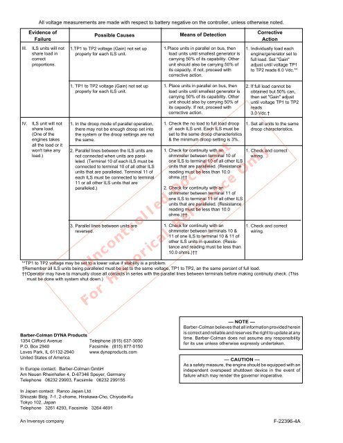
All voltage measurements are made with respect to battery negative on the controller, unless otherwise noted.<br />
Evidence of<br />
Failure<br />
Possible Causes<br />
Means of Detection<br />
Corrective<br />
Action<br />
<strong>II</strong>I.<br />
ILS units will not<br />
share load in<br />
correct<br />
proportions.<br />
1.TP1 to TP2 voltage (Gain) not set up<br />
properly for each ILS unit.<br />
1.Place units in parallel on bus, then<br />
load units until smallest generator is<br />
carrying 50% of its capability. Other<br />
unit should also be carrying 50% of<br />
its capacity. If not, proceed with<br />
corrective action.<br />
1. Individually load each<br />
engine/generator set to<br />
full load. Set "Gain"<br />
adjust until voltage TP1<br />
to TP2 reads 6.0 Vdc.**<br />
1. TP1 to TP2 voltage (Gain) not set up<br />
properly for each ILS unit.<br />
1. Place units in parallel on bus, then<br />
load units until smallest generator is<br />
carrying 50% of its capability. Other<br />
unit should also by carrying 50% of<br />
its capacity. If not, proceed with<br />
corrective action.<br />
2. If full load cannot be<br />
obtained but 50% can,<br />
then set "Gain" adjust<br />
until voltage TP1 to TP2<br />
reads<br />
3.0 Vdc.†<br />
IV.<br />
ILS unit will not<br />
share load.<br />
(One of the<br />
engines takes<br />
all the load or it<br />
won't take any<br />
load.)<br />
1. In the droop mode of parallel operation,<br />
there may not be enough droop set into<br />
the system or the droop settings are not<br />
the same.<br />
2. Parallel lines between the ILS units are<br />
not connected when units are paralleled.<br />
(Terminal 10 of each ILS must be<br />
connected to terminal 10 of all other ILS<br />
units that are paralleled. Terminal 11 of<br />
each ILS must be connected to terminal<br />
11 or all other ILS units that are<br />
paralleled.)<br />
3. Parallel lines between units are<br />
reversed.<br />
1. Check the no load to full load droop<br />
of each ILS unit. Each ILS must be<br />
set to the same droop characteristics<br />
& the minimum droop setting is 3%.<br />
1. Check for continuity with an<br />
ohmmeter between terminal 10 of<br />
one ILS to terminal 10 of all other ILS<br />
units that are paralleled. (Resistance<br />
reading must be less than 10.0<br />
ohms.)††<br />
2. Check for continuity with an<br />
ohmmeter between terminal 11 of<br />
one ILS to terminal 11 of all other ILS<br />
units that are paralleled. (Resistance<br />
reading must be less than 10.0<br />
ohms.)††<br />
1. Check for continuity with an<br />
ohmmeter between terminals 10 &<br />
11 of one ILS to terminal 10 & 11 of<br />
other ILS units in question. (Resistance<br />
and reading must be less than<br />
10.0 ohms.)††<br />
Uncontrolled Document<br />
1. Set all units to the same<br />
droop characteristics.<br />
1. Check and correct<br />
wiring.<br />
1. Check and correct<br />
wiring.<br />
**TP1 to TP2 voltage may be set to a lower value if stability is a problem.<br />
†Remember all ILS units being paralleled must be set to the same voltage, TP1 to TP2, an the same percent of full load.<br />
††Operator may have to manually close all contacts in series with the parallel lines between terminals before making continuity check. (This<br />
must be done with system shut down.)<br />
For Historical Reference Only<br />
Barber-Colman <strong>DYNA</strong> Products<br />
1354 Clifford Avenue Telephone (815) 637-3000<br />
P.O. Box 2940 Facsimile (815) 877-0150<br />
Loves Park, IL 61132-2940 www.dynaproducts.com<br />
United States of America<br />
In Europe contact: Barber-Colman GmbH<br />
Am Neuen Rheinhafen 4, D-67346 Speyer, Germany<br />
Telephone 06232 29903, Facsimile 06232 299155<br />
— NOTE —<br />
Barber-Colman believes that all information provided herein<br />
is correct and reliable and reserves the right to update at any<br />
time. Barber-Colman does not assume any responsibility<br />
for its use unless otherwise expressly undertaken.<br />
— CAUTION —<br />
As a safety measure, the engine should be equipped with an<br />
independent overspeed shutdown device in the event of<br />
failure which may render the governor inoperative.<br />
In Japan contact: Ranco Japan Ltd.<br />
Shiozaki Bldg. 7-1, 2-chome, Hirakawa-Cho, Chiyoda-Ku<br />
Tokyo 102, Japan<br />
Telephone 3261 4293, Facsimile 3264 4691<br />
An Invensys company<br />
F-22396-4A