DYNA II Digital Isochronous Load Sharing - ssdservice.pl
DYNA II Digital Isochronous Load Sharing - ssdservice.pl
DYNA II Digital Isochronous Load Sharing - ssdservice.pl

You also want an ePaper? Increase the reach of your titles
YUMPU automatically turns print PDFs into web optimized ePapers that Google loves.
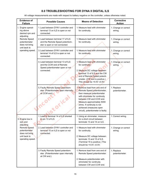
8.0 TROUBLESHOOTING FOR <strong>DYNA</strong> <strong>II</strong> DIGITAL ILS<br />
All voltage measurements are made with respect to battery negative on the controller, unless otherwise noted.<br />
Evidence of<br />
Failure<br />
I. Engine operating<br />
above<br />
desired rpm and<br />
adjusting<br />
Remote Speed<br />
potentiometer<br />
does not bring<br />
unit back to<br />
operating speed.<br />
<strong>II</strong>. Engine low in<br />
rpm and<br />
adjusting<br />
Remote Speed<br />
potentiometer<br />
does not bring<br />
unit back to<br />
operating speed.<br />
Possible Causes<br />
1. Lead between DYN1 controller and<br />
terminal 13 on ILS is open or not<br />
connected.<br />
2. Lead between terminal 17 of ILS<br />
and the Remote Speed potentiometer<br />
is open or not connected.<br />
3. Lead between DYN1 controller and<br />
terminal 14 of ILS is open or not<br />
connected.<br />
4. Lead between terminal 13 of ILS<br />
and the CCW end of Remote<br />
Speed potentiometer open or not<br />
connected.<br />
5. Faulty Remote Speed potentiometer.<br />
(Potentiometer open internally<br />
at CCW end.)<br />
1. Lead to terminal 14 of ILS shorted<br />
to pin 13 of ILS.<br />
2. Lead between DYN1 controller and<br />
terminal 15 on ILS is open or not<br />
connected.<br />
Means of Detection<br />
1. Measure lead with ohmmeter<br />
for continuity.<br />
1. Measure lead with ohmmeter<br />
for continuity.<br />
1. Measure lead with ohmmeter<br />
for continuity.<br />
1. Measure lead with ohmmeter<br />
for continuity.<br />
2. Measure DC voltage between<br />
terminal 13 of ILS and the CW<br />
end of Remote Speed potentiometer.<br />
(CW end is positive.)<br />
This should be +4.0V ±0.5V.<br />
1. Remove lead from one end of<br />
Remote Speed potentiometer,<br />
then measure potentiometer<br />
with ohmmeter for continuity<br />
between CW and CCW end.<br />
Measure approximately 5000<br />
ohms. If continuity is not<br />
achieved (measures open<br />
circuit), potentiometer is faulty.<br />
Uncontrolled Document<br />
1. Using an ohmmeter, measure<br />
for a short circuit between<br />
terminals 13 and 14 on ILS.<br />
For Historical Reference Only<br />
1. Measure lead with ohmmeter<br />
for continuity.<br />
2. Measure DC voltage between<br />
terminals 13 and 15 of ILS.<br />
(Terminal 15 is positive.) This<br />
should be +4.0V ±0.5V.<br />
Corrective<br />
Action<br />
1. Change or correct<br />
wiring.<br />
1. Change or correct<br />
wiring.<br />
1. Change or correct<br />
wiring.<br />
1. Change or correct<br />
wiring.<br />
1. Re<strong>pl</strong>ace<br />
potentiometer.<br />
1. Correct wiring.<br />
1. Change or correct<br />
wiring.<br />
3. Faulty Remote Speed potentiometer.<br />
(Potentiometer open internally<br />
at CW end.)<br />
1. Remove lead from one end of<br />
Remote Speed potentiometer.<br />
2. Measure potentiometer with<br />
ohmmeter for continuity<br />
between CW and CCW end.<br />
1. Re<strong>pl</strong>ace<br />
potentiometer.<br />
15