DYNA II Digital Isochronous Load Sharing - ssdservice.pl
DYNA II Digital Isochronous Load Sharing - ssdservice.pl
DYNA II Digital Isochronous Load Sharing - ssdservice.pl

You also want an ePaper? Increase the reach of your titles
YUMPU automatically turns print PDFs into web optimized ePapers that Google loves.
. The “<strong>Load</strong> Pulse” adjustment should be set to provide the<br />
minimum pulse necessary to meet the required transient<br />
response of the system.<br />
c. Set “<strong>Load</strong> Pulse” potentiometer fully counterclockwise.<br />
d. If a recording of transient response is necessary, connect<br />
recorder to engine/generator under test.<br />
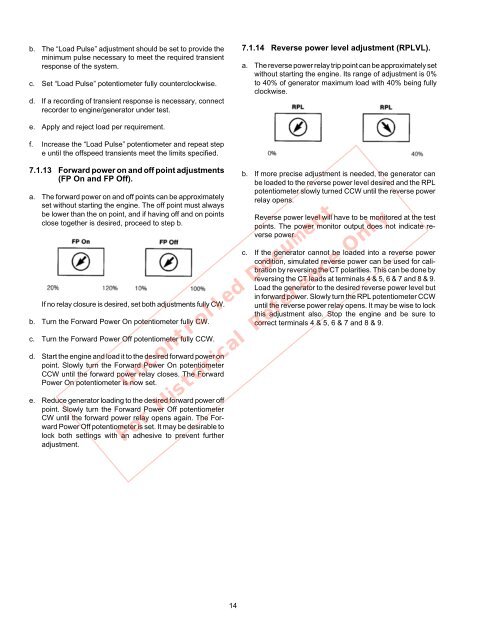
7.1.14 Reverse power level adjustment (RPLVL).<br />
a. The reverse power relay trip point can be approximately set<br />
without starting the engine. Its range of adjustment is 0%<br />
to 40% of generator maximum load with 40% being fully<br />
clockwise.<br />
e. Ap<strong>pl</strong>y and reject load per requirement.<br />
f. Increase the “<strong>Load</strong> Pulse” potentiometer and repeat step<br />
e until the offspeed transients meet the limits specified.<br />
7.1.13 Forward power on and off point adjustments<br />
(FP On and FP Off).<br />
a. The forward power on and off points can be approximately<br />
set without starting the engine. The off point must always<br />
be lower than the on point, and if having off and on points<br />
close together is desired, proceed to step b.<br />
If no relay closure is desired, set both adjustments fully CW.<br />
b. Turn the Forward Power On potentiometer fully CW.<br />
c. Turn the Forward Power Off potentiometer fully CCW.<br />
d. Start the engine and load it to the desired forward power on<br />
point. Slowly turn the Forward Power On potentiometer<br />
CCW until the forward power relay closes. The Forward<br />
Power On potentiometer is now set.<br />
e. Reduce generator loading to the desired forward power off<br />
point. Slowly turn the Forward Power Off potentiometer<br />
CW until the forward power relay opens again. The Forward<br />
Power Off potentiometer is set. It may be desirable to<br />
lock both settings with an adhesive to prevent further<br />
adjustment.<br />
Uncontrolled Document<br />
b. If more precise adjustment is needed, the generator can<br />
be loaded to the reverse power level desired and the RPL<br />
potentiometer slowly turned CCW until the reverse power<br />
relay opens.<br />
Reverse power level will have to be monitored at the test<br />
points. The power monitor output does not indicate reverse<br />
power.<br />
c. If the generator cannot be loaded into a reverse power<br />
condition, simulated reverse power can be used for calibration<br />
by reversing the CT polarities. This can be done by<br />
reversing the CT leads at terminals 4 & 5, 6 & 7 and 8 & 9.<br />
<strong>Load</strong> the generator to the desired reverse power level but<br />
in forward power. Slowly turn the RPL potentiometer CCW<br />
until the reverse power relay opens. It may be wise to lock<br />
this adjustment also. Stop the engine and be sure to<br />
correct terminals 4 & 5, 6 & 7 and 8 & 9.<br />
For Historical Reference Only<br />
14