DYNA II Digital Isochronous Load Sharing - ssdservice.pl
DYNA II Digital Isochronous Load Sharing - ssdservice.pl
DYNA II Digital Isochronous Load Sharing - ssdservice.pl

You also want an ePaper? Increase the reach of your titles
YUMPU automatically turns print PDFs into web optimized ePapers that Google loves.
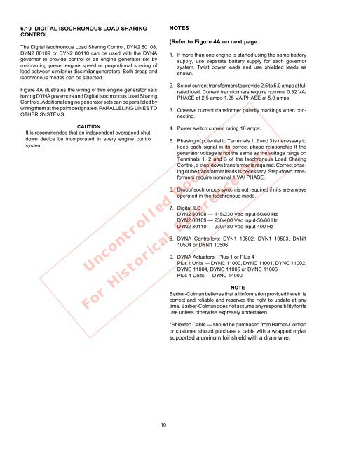
6.10 DIGITAL ISOCHRONOUS LOAD SHARING<br />
CONTROL<br />
The <strong>Digital</strong> <strong>Isochronous</strong> <strong>Load</strong> <strong>Sharing</strong> Control, DYN2 80108,<br />
DYN2 80109 or DYN2 80110 can be used with the <strong>DYNA</strong><br />
governor to provide control of an engine generator set by<br />
maintaining preset engine speed or proportional sharing of<br />
load between similar or dissimilar generators. Both droop and<br />
isochronous modes can be selected.<br />
Figure 4A illustrates the wiring of two engine generator sets<br />
having <strong>DYNA</strong> governors and <strong>Digital</strong> <strong>Isochronous</strong> <strong>Load</strong> <strong>Sharing</strong><br />
Controls. Additional engine generator sets can be paralleled by<br />
wiring them at the point designated, PARALLELING LINES TO<br />
OTHER SYSTEMS.<br />
NOTES<br />
(Refer to Figure 4A on next page.<br />
1. If more than one engine is started using the same battery<br />
sup<strong>pl</strong>y, use separate battery sup<strong>pl</strong>y for each governor<br />
system. Twist power leads and use shielded leads as<br />
shown.<br />
2. Select current transformers to provide 2.5 to 5.0 amps at full<br />
rated load. Current transformers require nominal 0.32 VA/<br />
PHASE at 2.5 amps 1.25 VA/PHASE at 5.0 amps<br />
3. Observe current transformer polarity markings when connecting.<br />
CAUTION<br />
It is recommended that an independent overspeed shutdown<br />
device be incorporated in every engine control<br />
system.<br />
4. Power switch current rating 10 amps.<br />
5. Phasing of potential to Terminals 1, 2 and 3 is necessary to<br />
keep each signal in its correct phase relationship If the<br />
generator voltage is not the same as the voltage range on<br />
Terminals 1, 2 and 3 of the <strong>Isochronous</strong> <strong>Load</strong> <strong>Sharing</strong><br />
Control, a step-down transformer is required. Correct phasing<br />
of the transformer leads is necessary. Step-down transformers<br />
require nominal 1 VA/ PHASE.<br />
6. Droop/lsochronous switch is not required if nits are always<br />
operated in the <strong>Isochronous</strong> mode.<br />
7. <strong>Digital</strong> ILS<br />
DYN2 80108 — 115/230 Vac input-50/60 Hz<br />
DYN2 80109 — 230/480 Vac input-50/60 Hz<br />
DYN2 80110 — 230/480 Vac input-400 Hz<br />
Uncontrolled Document<br />
8. <strong>DYNA</strong> Controllers: DYN1 10502, DYN1 10503, DYN1<br />
10504 or DYN1 10506<br />
9. <strong>DYNA</strong> Actuators: Plus 1 or Plus 4<br />
Plus 1 Units — DYNC 11000, DYNC 11001, DYNC 11002,<br />
DYNC 11004, DYNC 11005 or DYNC 11006<br />
Plus 4 Units — DYNC 14000<br />
NOTE<br />
Barber-Colman believes that all information provided herein is<br />
correct and reliable and reserves the right to update at any<br />
time. Barber-Colman does not assume any responsibility for its<br />
use unless otherwise expressly undertaken .<br />
For Historical Reference Only<br />
*Shielded Cable — should be purchased from Barber-Colman<br />
or customer should purchase a cable with a wrapped mylar<br />
supported aluminum foil shield with a drain wire.<br />
10