COMPIT 2004 in Siguenza/ Spain - Institut für Entwerfen von ...
COMPIT 2004 in Siguenza/ Spain - Institut für Entwerfen von ...
COMPIT 2004 in Siguenza/ Spain - Institut für Entwerfen von ...

You also want an ePaper? Increase the reach of your titles
YUMPU automatically turns print PDFs into web optimized ePapers that Google loves.
3 rd International Conference on<br />
Computer and IT Applications <strong>in</strong> the Maritime Industries<br />
<strong>COMPIT</strong>’04<br />
Siguënza, 9-12 May <strong>2004</strong><br />
Volker Bertram, Manuel Armada (Ed.)<br />
Sponsored by<br />
This work relates to Department of the Navy Grant N00014-04-1-1055 issued by the Office of<br />
Naval Research Global. The United States Government has a royalty-free license throughout the<br />
world <strong>in</strong> all copyrightable material conta<strong>in</strong>ed here<strong>in</strong>.<br />
1
Index<br />
Volker Bertram 5<br />
Towards Intelligent Simulation-based Ship Design<br />
Marco Ferrando, Andrea Lommi, Antonio Traverso 17<br />
Use of Genetic Algorithms <strong>in</strong> Propeller Foil Design<br />
Jörn H<strong>in</strong>nenthal 1 , Stefan Harries 27<br />
A Systematic Study on Pos<strong>in</strong>g and Solv<strong>in</strong>g the Problem of Pareto Optimal Ship Rout<strong>in</strong>g<br />
Otto Millbourn 36<br />
Concurrent Eng<strong>in</strong>eer<strong>in</strong>g through the Supply Cha<strong>in</strong> from Ship Owner to Supplier<br />
Hans Wuttke, Andreas Schwill, Frank Domeyer 42<br />
An E-Commerce Platform for Eng<strong>in</strong>eer<strong>in</strong>g Services <strong>in</strong> Shipbuild<strong>in</strong>g<br />
Tobias Haack, Stefan Krüger 52<br />
Propulsion Plant Models for Nautical Manoeuvre Simulations<br />
Lawrence Henesey 2 , Paul Davidsson, Jan A. Persson 61<br />
Us<strong>in</strong>g Simulation <strong>in</strong> Evaluat<strong>in</strong>g Berth Allocation at a Conta<strong>in</strong>er Term<strong>in</strong>al<br />
Eberhard Blümel, Leonid Novitski 73<br />
Introduction to BALTPORTS-IT: Applications of Simulation and IT-Solutions <strong>in</strong> the Baltic Port Areas<br />
Peter Weiss 1 , Yann Le Page, Frédéric Schom, Ala<strong>in</strong> Fidani 81<br />
Robot Applications <strong>in</strong> the Field of Shipbuild<strong>in</strong>g<br />
Vedeesh Sahajpal 86<br />
An <strong>in</strong>telligent GA based AIS FATDMA scheduler<br />
Jonathan M. Ross 98<br />
A Practical Approach for Ship Construction Cost Estimat<strong>in</strong>g<br />
Robert Bronsart, Steffen Gau, Diane Luckau, Wolfgang Sucharowski 111<br />
Communication <strong>in</strong> ship design networks<br />
Torsten Fischer, Hermann Gehr<strong>in</strong>g 122<br />
A Multi-Agent based Approach for Solv<strong>in</strong>g the Vehicle Transshipment Problem<br />
Meelis Mäesalu, Jerzy Matusiak 131<br />
Visualisation of Ship Motions <strong>in</strong> Waves and dur<strong>in</strong>g Ground<strong>in</strong>g for Simulators<br />
Peter Weiss 1 , Fivos Andritsos, Frédéric Schom, Ala<strong>in</strong> Fidani 140<br />
Innovative Robotic Solutions for the Survey and Certification of Ships and Mobile Offshore Units<br />
Yuichi Sasaki, Hiroyuki Yamato, Shoichi Enomoto 148<br />
Research on Industrial Eng<strong>in</strong>eer<strong>in</strong>g System by us<strong>in</strong>g Wearable PC<br />
1 Partially supported by SENER<br />
2 Partially sponsored by Tribon Solutions<br />
2
Patrick Hupe, Uwe Langbecker, Mubashir Aziz, Joachim W. Schmidt 154<br />
Mobile and Web-based Services for Ship Operation and Survey:A Portal-centric Approach<br />
Jan Henrik Weychardt, Berend Bohlmann 165<br />
FEM Supported Alignment of Power Tra<strong>in</strong> Components<br />
Evangelos K. Boulougouris, Apostolos D. Papanikolaou 175<br />
Optimisation of the Survivability of Naval Ships by Genetic Algorithms<br />
Jan Jaap Nieuwenhuis, Ubald Nienhuis 190<br />
Knowledge and Data Reuse <strong>in</strong> Ship System Design and Eng<strong>in</strong>eer<strong>in</strong>g<br />
Zbigniew Pietrzykowski, Janusz Uriasz 204<br />
The Ship Doma<strong>in</strong> <strong>in</strong> a Deep-Sea Area<br />
Bastiaan Veelo 2 212<br />
Shape Modification of Hull Models <strong>in</strong> H-rep<br />
Sipke Vijver 1 , Hotze Boonstra, Herbert J. Koelman, Erw<strong>in</strong> D. St<strong>in</strong>stra 223<br />
Apply<strong>in</strong>g Meta-Models to the Probabilistic Damage Stability<br />
Hugo Grimmelius, Douwe Stapersma, Paul Schulten 236<br />
Ship Propulsion Control: A Fresh View<br />
Desmond Simpson, Ludwig Furstenberg 252<br />
Distribut<strong>in</strong>g Operational Simulation Systems across South African Ports<br />
Jenny Coenen, Mart<strong>in</strong> van Hees, Ubald Nienhuis 263<br />
Knowledge-based Concurrent Eng<strong>in</strong>eer<strong>in</strong>g <strong>in</strong> One-off Ship Design<br />
Jean-Yves Pradillon 278<br />
ODIGO - Modell<strong>in</strong>g and Simulat<strong>in</strong>g Crowd Movement onboard Ships<br />
Uwe Langbecker, Ricardo Pereira 290<br />
UTHLANDE – An Extensible Platform for Hydromechanic Calculation Modules<br />
Patrick Queutey, Michel Visonneau 300<br />
Three-dimensional CFD Simulations Us<strong>in</strong>g a Free-Surface Captur<strong>in</strong>g Strategy<br />
Manuel Armada, Pablo González de Santos, Manuel Prieto, Elena García,<br />
Teodor Ak<strong>in</strong>fiev Roemi Fernández, Hector Montes, Samir Nabulsi,<br />
Luis Pedraza, Roberto Ponticelli, Javier Sarriá, Joaquín Estremera 315<br />
State of the art <strong>in</strong> climb<strong>in</strong>g and walk<strong>in</strong>g robots<br />
Antonio P<strong>in</strong>to, Daniele Peri, Emilio F. Campana 322<br />
Global Optimization Algorithms <strong>in</strong> Naval Hydrodynamics<br />
Virgil Mutu, Ovidiu Ionas 334<br />
Computer Applications and Technologies at Ship Design Group Galati<br />
Bekir S. Türkmen 2 , Osman Turan 340<br />
An Application Study of Multi-Agent Systems <strong>in</strong> Multi-Criteria Ship Design Optimisation<br />
3
Rafael de Góngora 354<br />
A New Collaborative Eng<strong>in</strong>eer<strong>in</strong>g Management Tool for Shipbuild<strong>in</strong>g<br />
Martijn Neef, Anthonie van Lieburg 363<br />
Applications of Self-Organiz<strong>in</strong>g Systems <strong>in</strong> Maritime Environments<br />
Christian Massow, Ivan Siksne-Pedersen 378<br />
Computer Integrated Plann<strong>in</strong>g and Resource Management <strong>in</strong> Shipbuild<strong>in</strong>g<br />
Patrick Couser, Andrew Mason, Garth Mason, Cameron R. Smith, Brian R. <strong>von</strong> Konsky 391<br />
Artificial Neural Networks for Hull Resistance Prediction<br />
Reidar Tronstad, Antonio Rodriguez 403<br />
Automation Tools <strong>in</strong> the Design Process<br />
Andreas Bortfeldt 419<br />
A Heuristic for the Conta<strong>in</strong>er Pre-Marshall<strong>in</strong>g Problem<br />
David E. Hess, William E. Faller, Edward S. Ammeen, Thomas C. Fu 430<br />
Neural Networks for Naval Applications<br />
Mario Dogliani, Dracos Vassalos, Tom Strang 447<br />
Evacuation Notation – a New Concept to Boost Passenger Evacuation Performance <strong>in</strong> the Cruise<br />
Industry<br />
M.S. Seif, E. Jahanbakhsh 459<br />
Neural Networks Model for Ship Maneuver<br />
Wilfried Abels, Stefan Krüger 470<br />
Correlation Strategy for Propeller Excited Pressure Fluctuations<br />
Index of authors 479<br />
Call for Papers <strong>COMPIT</strong>’05 at last page<br />
Email the authors to obta<strong>in</strong> an electronic copy often conta<strong>in</strong><strong>in</strong>g figures <strong>in</strong> colour.<br />
4
Towards Intelligent Simulation-Based Design<br />
Volker Bertram, ENSIETA, Brest/France, volker.bertram@ensieta.fr<br />
Abstract<br />
Proposed models for the ship design process fail to conv<strong>in</strong>ce. The classical design spiral model is frequently<br />
rejected by modern ship designers, but design is iterative and several basic elements are repeated<br />
used, albeit not always <strong>in</strong> same order. The paper gives some historical perspective before review<strong>in</strong>g<br />
some modern developments <strong>in</strong> computer-aided ship design, draw<strong>in</strong>g frequently, but not exclusively,<br />
on the experience of the author. Techniques covered <strong>in</strong>clude knowledge and decision, generation<br />
of solutions, analysis and visualization.<br />
1. Introduction<br />
The design process is often described as a design spiral follow<strong>in</strong>g the <strong>in</strong>itial model of Evans (1959).<br />
This model has been ''ref<strong>in</strong>ed'' by propos<strong>in</strong>g spiral<strong>in</strong>g cones, Andrews (1981), or <strong>in</strong>terconnected<br />
spirals, Mistree et al. (1990), but <strong>in</strong> essence it was the spiral <strong>in</strong> disguise, Fig.1. This model for ship<br />
design has been rejected frequently, as the sequence of analyses and decisions is not as sequential as<br />
the spiral models suggest. Ship design seems to be <strong>in</strong>stead a rather chaotic process of comb<strong>in</strong><strong>in</strong>g<br />
various analyses with ‘<strong>in</strong>telligent’ or ‘creative’ generation of solutions, sometimes <strong>in</strong> parallel, which<br />
are then analyzed, evaluated, possibly rejected or modified. The sequence of these elements <strong>in</strong> the<br />
design process changes even for absolutely the same design task from designer to designer. There is<br />
no absolute criterion what is the best design process sequence. While different designers may well<br />
apply the same tools (or at least tools of comparable performance power), some designers manage to<br />
get better results.<br />
Evans (1959) Andrews (1981) Mistree et al. (1990)<br />
Fig.1: Ship design has been frequently described as a design spiral process<br />
I see this <strong>in</strong> rough analogy to nature. The DNA is composed of the 4 same basic elements, whether it<br />
is the DNA of a bacterium or the DNA of a Nobel prize laureate. Apparently the proper comb<strong>in</strong>ation<br />
of the same 4 simple elements can make a big difference. Similarly, one could use music as an<br />
analogue with a (relatively) small number of str<strong>in</strong>g, keys or notes used by masters and beg<strong>in</strong>ners<br />
alike, but with big differences. Rather than speculat<strong>in</strong>g whether computers <strong>in</strong> the (distant) future may<br />
outperform humans <strong>in</strong> the design process, I focus on the “basic elements” of ship design and highlight<br />
some recent developments. The ship design process rema<strong>in</strong>s computer-aided, but the computer<br />
accelerates the process and improves the “classical toolkit” of the designer. The follow<strong>in</strong>g is neither<br />
mutually exclusive, nor collectively exhaustive. It is merely <strong>in</strong>tended to br<strong>in</strong>g some structure <strong>in</strong>to the<br />
review. Basic elements <strong>in</strong> ship design are then for me:<br />
1. Generation (creative, <strong>in</strong>telligent or systematic creation of solutions)<br />
2. Analysis (evaluation, simulation, computation)<br />
3. Visualization (representation, communication)<br />
4. Decision (knowledge, identification, learn<strong>in</strong>g)<br />
5
2. Generation<br />
The generation of solutions is rather a creative task. While “Artificial Intelligence” is by now widely<br />
accepted as an additional useful tool also for naval architects, nobody contemplates (seriously)<br />
“Artificial Creativity”. And yet the computer may help us to generate better solutions, namely <strong>in</strong> the<br />
context of concept exploration and/or optimization, Bertram (2003a).<br />
A concept exploration models (CEM) generates a large set of candidate solutions by vary<strong>in</strong>g design<br />
variables. Each of these solutions is evaluated, stored and graphically displayed, so that the designer<br />
gets a feel<strong>in</strong>g how certa<strong>in</strong> variables <strong>in</strong>fluence the performance of the design, e.g. Erikstad (1996).<br />
This prelim<strong>in</strong>ary “exploration” is often necessary to determ<strong>in</strong>e suitable optimization objectives and<br />
constra<strong>in</strong>ts. This approach, albeit under the mislead<strong>in</strong>g label of “multi-objective optimization” is realized<br />
<strong>in</strong> the modeFRONTIER optimization environment, e.g. Abt et al. (2003). The approach is <strong>in</strong> reality<br />
a prelim<strong>in</strong>ary concept exploration generat<strong>in</strong>g many solutions and def<strong>in</strong><strong>in</strong>g Pareto surfaces , Fig.2,<br />
which then allow the user to reject certa<strong>in</strong> solutions (realiz<strong>in</strong>g at this stage constra<strong>in</strong>ts which were so<br />
far not explicitly stated) and f<strong>in</strong>d<strong>in</strong>g an “optimum” solution (with<strong>in</strong> the more or less simplified optimization<br />
model us<strong>in</strong>g more or less erroneous approximations for evaluat<strong>in</strong>g candidate properties).<br />
Despite rema<strong>in</strong><strong>in</strong>g short-com<strong>in</strong>gs, optimization shells as modeFRONTIER or the German development<br />
DELPHI, e.g. Bertram et al. (1998), Gudenschwager (2003), allow the designer to focus on the<br />
design task and allow by now models of suitable complexity to <strong>in</strong>deed aid the practical design process.<br />
Sett<strong>in</strong>g up a suitable optimization model, rather than programm<strong>in</strong>g yet another optimization algorithm,<br />
is the task for the naval architect.<br />
Fig.2: Result of form optimization with Pareto<br />
Frontier for FantaRoRo, source: TU Berl<strong>in</strong><br />
Fig.3: Schenzle’s ‘design for production’ hull,<br />
Bertram and El Moctar (2003)<br />
New and improved simulation tools can be <strong>in</strong>tegrated <strong>in</strong> optimization models allow<strong>in</strong>g new or more<br />
realistic applications. Possibilities are as numerous as the rapidly develop<strong>in</strong>g simulation tools. Examples<br />
from my own research <strong>in</strong>terest and experience <strong>in</strong>clude:<br />
• Hull production costs are so far rarely quantified <strong>in</strong> the design. Bottom-up approaches (decompos<strong>in</strong>g<br />
the production process <strong>in</strong>to appropriate subtasks like profile and plate bend<strong>in</strong>g,<br />
weld<strong>in</strong>g <strong>in</strong> various positions and techniques, etc.) are needed to suitably reflect the <strong>in</strong>fluence<br />
of local hull shape changes, Bertram and El Moctar (2003). Rigo (2003) presents how bottom-up<br />
approaches can now be applied successfully to support shipyard structural design<br />
work. Hulls optimized for production costs without hydrodynamic sacrifices appear feasible,<br />
Fig.3.<br />
• Optimization uses often an economic criterion. Ships have been optimized <strong>in</strong> the past for<br />
build<strong>in</strong>g costs (“shipyard’s view”) or yield <strong>in</strong>clud<strong>in</strong>g operational cost and <strong>in</strong>come (“ship<br />
owner’s view”). Environmental aspects have been largely neglected <strong>in</strong> optimization with the<br />
notable exception of wash, e.g. Koushan et al. (2002). However, ship emissions cause <strong>in</strong>di-<br />
6
ectly damage <strong>in</strong> terms of greenhouse effect, acid ra<strong>in</strong>, eutrophication etc. The associated<br />
costs are ‘external costs’ which have to be considered on a scale of national or global economies.<br />
Legislation generally has the trend to <strong>in</strong>ternalize external costs. Isensee and Bertram<br />
(<strong>2004</strong>) present first steps <strong>in</strong> quantify<strong>in</strong>g ship emissions <strong>in</strong> terms of external costs, thus open<strong>in</strong>g<br />
the door for optimization studies <strong>in</strong>clud<strong>in</strong>g external costs (“state’s view”).<br />
• Ship hull optimization benefits from advances <strong>in</strong> hull description, namely parametric hull description,<br />
and progress <strong>in</strong> CFD, e.g. Harries (1998). A practical problem is that the hull description<br />
requires consideration of the <strong>in</strong>tended optimization at the time of sett<strong>in</strong>g up the parametric<br />
model. Thus exist<strong>in</strong>g CAD descriptions are usually of little value and a new hull description<br />
(of an exist<strong>in</strong>g hull) is required for an optimization. A diploma thesis at ENSIETA<br />
compared three commercial CAD systems (NAPA, CATIA, Friendship) offer<strong>in</strong>g parametric<br />
descriptions us<strong>in</strong>g the a generic ro-ro ship (FantaRoRo) as test case, Fig.4, Butruille (2002).<br />
Table I gives the (subjective) evaluation of Butruille (2002) who po<strong>in</strong>ted out rema<strong>in</strong><strong>in</strong>g need<br />
for research and development <strong>in</strong> parametric ship hull description. Also CFD methods employed<br />
feature still large (and variable) errors <strong>in</strong> predict<strong>in</strong>g e.g. resistance values requir<strong>in</strong>g<br />
care and often iterative ref<strong>in</strong>ements of the optimization model to obta<strong>in</strong> plausible results, e.g.<br />
Abt et al. (2003). Progress <strong>in</strong> CFD method and experience <strong>in</strong> how to set up models should<br />
however improve the picture and let formal hull optimization at least for bulbous bows become<br />
a practical reality with<strong>in</strong> the next decade.<br />
Table I: Abbreviated table of evaluation for parametric ship hull description benchmark<br />
study, Butruille (2002)<br />
NAPA FRIENDSHIP CATIA<br />
Ability to approximate<br />
given surface with<br />
parametric description<br />
Not tested. Handl<strong>in</strong>g of<br />
parameters does not seem<br />
simple.<br />
average<br />
(good for<br />
conventional forms)<br />
Facility of parameterization<br />
(time needed for user)<br />
quite slow fast (GUI needed) average<br />
(conventional forms)<br />
Grid generation for CFD simple simple average<br />
code<br />
IGES export good good average<br />
Surface quality<br />
average<br />
(too sensitive on changes<br />
<strong>in</strong> parameters)<br />
average<br />
(some problems at<br />
junctions)<br />
average<br />
(sometimes bad w/o<br />
apparent reason)<br />
Robustness on parameter poor quite robust poor<br />
variations<br />
Proper program end <strong>in</strong> case<br />
of error <strong>in</strong> attempt to create<br />
parametric surface<br />
Duration for surface<br />
generation<br />
no<br />
(sometimes program not<br />
clos<strong>in</strong>g <strong>in</strong> case of error)<br />
yes<br />
(often without error<br />
message)<br />
good<br />
yes<br />
1 m<strong>in</strong>ute some seconds 2-4 m<strong>in</strong>utes<br />
Ship rout<strong>in</strong>g (i.e. optimization of a ship’s course and speed) is a special application of optimization<br />
which couples naval architecture and ship operation. Both formal optimization and techniques of<br />
Artificial Intelligence (AI) have been proposed for ship rout<strong>in</strong>g. We dist<strong>in</strong>guish between strategical<br />
and tactical rout<strong>in</strong>g. Strategical rout<strong>in</strong>g has typical time periods of hours or days, tactical rout<strong>in</strong>g has<br />
typical time periods of m<strong>in</strong>utes. Tactical rout<strong>in</strong>g concerns e.g. collision avoidance, e.g. Kasai and<br />
Bertram (1996), Bertram (2000b). PrISM is a tactical ship rout<strong>in</strong>g system developed as a decision<br />
support system for the French navy <strong>in</strong> f<strong>in</strong>d<strong>in</strong>g best course and speed for a frigate dur<strong>in</strong>g helicopter<br />
land<strong>in</strong>g, Capitant and Bertram (2003). The system comb<strong>in</strong>es various AI techniques (genetic<br />
algorithms for seaway identification, fuzzy logic <strong>in</strong> evaluat<strong>in</strong>g safety level, expert system for criteria<br />
of safety) with a graphical user <strong>in</strong>terface (GUI), Fig.5. By late 2003, the system was <strong>in</strong>stalled and<br />
subject to evaluation by the French navy. Sp<strong>in</strong>-off modifications of the system to tugs and towed ships<br />
are subject to pend<strong>in</strong>g research applications. Progress <strong>in</strong> telecommunication, optimization<br />
7
environments and practical AI tools motivate renewed research efforts for strategical rout<strong>in</strong>g, which<br />
after at least three decades of research can be considered as a “classical” optimization topic.<br />
Fig.4: Parametric description of ro-ro ship bow<br />
<strong>in</strong> CATIA, Butruille (2002)<br />
Fig.5: GUI of PrISM tactical rout<strong>in</strong>g system,<br />
Capitant and Bertram (2003)<br />
3. Analysis and Simulation<br />
The word simulation is derived from the Lat<strong>in</strong> word “simulare” which can be translated as “to<br />
reproduce”. The VDI (Society of German Eng<strong>in</strong>eers) def<strong>in</strong>es the technical term “simulation” as<br />
follows: “Simulation is the reproduction of a system with its dynamic processes <strong>in</strong> a runn<strong>in</strong>g model to<br />
achieve cognition which can be referred to reality”. Accord<strong>in</strong>g to the Oxford dictionary "to simulate"<br />
means "to imitate conditions of a situation or process", specifically "to produce a computer model of a<br />
process". In this sense virtually all computer models used <strong>in</strong> the design process of ships would qualify<br />
as simulations. The field of such computer models <strong>in</strong> modern shipbuild<strong>in</strong>g processes covers a wide<br />
field, <strong>in</strong>clud<strong>in</strong>g from transport economics, CAD models <strong>in</strong>volv<strong>in</strong>g Virtual Reality and ergonomics,<br />
f<strong>in</strong>ite element analyses, hydrostatic and hydrodynamic analyses, production analyses, etc.<br />
Stability analyses were among the first applications of computers <strong>in</strong> naval architecture. Today, the<br />
naval architect can perform stability analyses <strong>in</strong> <strong>in</strong>tact and damaged conditions quasi at the push of a<br />
button. Two other “classical” applications of computer simulations for ships are CFD (computational<br />
fluid dynamics), e.g. Bertram (2000a), and FEA (f<strong>in</strong>ite-element analyses). Both have been used for<br />
several decades now to support ship design, but today’s CFD and FEA applications are of course far<br />
more sophisticated than 20 years ago. In CFD, we see today unsteady viscous flow simulations (albeit<br />
with simplified turbulence model<strong>in</strong>g) with complex two-phase flow simulation (either wave formation<br />
<strong>in</strong>clud<strong>in</strong>g wave break<strong>in</strong>g or cavitation), e.g. Fig.6. In FEA, unsteady nonl<strong>in</strong>ear analyses are feasible<br />
(up to simulations of ships collid<strong>in</strong>g with other ships, ruptur<strong>in</strong>g the ship hull). New materials like<br />
composites with anisotropic properties, Fig.7, high-frequency analyses (e.g. sound propagation <strong>in</strong><br />
structures) and fracture propagation <strong>in</strong>volv<strong>in</strong>g discont<strong>in</strong>uous material properties pose new challenges<br />
for cont<strong>in</strong>ued research. Also the comb<strong>in</strong>ation of hydrodynamics (CFD) and structural mechanics<br />
(FEA) <strong>in</strong> hydro-elastic <strong>in</strong>teraction between fluid and structure is a field of research where many<br />
problems are yet to be solved. Hydro-elastic <strong>in</strong>teraction is for example important <strong>in</strong> determ<strong>in</strong><strong>in</strong>g<br />
slamm<strong>in</strong>g loads, e.g. Constant<strong>in</strong>escu et al. (<strong>2004</strong>).<br />
The last decade has seen a rapid profusion of assorted simulations for ships cover<strong>in</strong>g much more than<br />
classical hydrostatics, CFD analyses of hull and propeller, or FEA. CFD has been extended to “w<strong>in</strong>d,<br />
fire, and ice”:<br />
• Aerodynamic analyses of ship superstructures and ventilated rooms, e.g. Fig.8, Schmode and<br />
Bertram (2002),<br />
• simulations of fire <strong>in</strong> ship rooms, Fig.9, Junalik et al. (2003),<br />
• even numerical ice-break<strong>in</strong>g, Fig.10.<br />
8
Fig.7: FEA of a catamaran made of composite<br />
material, Luco et al. (2002).<br />
← Fig.6: CFD analysis of hull, propeller and<br />
rudder, source: Mitsubishi H.I.<br />
Fig.8: Aerodynamic CFD analysis for fast ship,<br />
Schmode and Bertram (2002)<br />
Fig.9: Fire simulation for ship cab<strong>in</strong>,<br />
source: RIAM<br />
Fig.10: Simulation of ice-break<strong>in</strong>g at HSVA<br />
Fig.11: Ship evacuation simulation us<strong>in</strong>g DES,<br />
Galea et al. (2003)<br />
Despite impressive progress, fire simulations for ships face many problems. Classical zonal models<br />
are efficient, but questionable <strong>in</strong> tall rooms with strong 3-d effects. Standard RANSE (Reynoldsaveraged<br />
Navier-Stokes equations) solvers are not capable to reproduce the evolution of large eddy<br />
structures observed <strong>in</strong> most fire plumes. However, resolution of these eddies <strong>in</strong> large-eddy simulations<br />
(LES) is prohibitively time-consum<strong>in</strong>g. Ship fire simulations face thus the classical dilemma of large<br />
complex geometries (if e.g. a whole deck or even several decks are to be simulated) with strong local<br />
changes <strong>in</strong> the simulated properties (temperature, smoke density, etc). Appropriate compromises<br />
between available resources and accuracy of the model will change <strong>in</strong> time as more powerful<br />
simulation tools ga<strong>in</strong> practical application maturity.<br />
9
In the simulation of ice-break<strong>in</strong>g, we see already many <strong>in</strong>dividual (discrete) ice floes <strong>in</strong> Fig.10. This<br />
simulation comb<strong>in</strong>es then classical simulation for cont<strong>in</strong>uous media (water) with discrete elements.<br />
Fire simulation is <strong>in</strong>creas<strong>in</strong>gly also comb<strong>in</strong>ed with discrete simulation of passengers <strong>in</strong> evacuation<br />
dur<strong>in</strong>g a fire, e.g. Galea et al. (2003). Discrete event simulation (DES) has evolved rapidly and has<br />
proven to be versatile and powerful tool for many applications support<strong>in</strong>g ship design.<br />
Fig.12: DES for shipyard simulation at FSG,<br />
Ste<strong>in</strong>hauer (2003)<br />
Fig.13: Expert system DES for port simulation,<br />
Simpson et al. (2003)<br />
Discrete event simulation is used <strong>in</strong> practice <strong>in</strong> several shipyards to support operational and strategical<br />
plann<strong>in</strong>g of the shipyard operation, particularly <strong>in</strong> the assembly-l<strong>in</strong>e type of subassembly, e.g.<br />
Ste<strong>in</strong>hauer (2003), Fig.12. The actual “theory” beh<strong>in</strong>d DES is very simple <strong>in</strong> comparison to the<br />
classical cont<strong>in</strong>uous simulation. In DES, <strong>in</strong>dividual elements are l<strong>in</strong>ked and certa<strong>in</strong> events trigger the<br />
execution of other events. Each event is associated with certa<strong>in</strong> properties (attributes). E.g. a stiffener<br />
of certa<strong>in</strong> length is welded to a plate with a weld<strong>in</strong>g method of certa<strong>in</strong> speed, result<strong>in</strong>g <strong>in</strong> a certa<strong>in</strong><br />
time before the weld<strong>in</strong>g is f<strong>in</strong>ished and the weld<strong>in</strong>g head can be moved to another position (aga<strong>in</strong><br />
associated with a certa<strong>in</strong> speed). In an object-oriented environment, we have then various objects<br />
which can be processed <strong>in</strong> parallel or <strong>in</strong> sequence, depend<strong>in</strong>g on certa<strong>in</strong> conditions. The logic of the<br />
set-up resembles a critical path network plan. The difficulty is rather <strong>in</strong> realiz<strong>in</strong>g the <strong>in</strong>dividual<br />
elements, how they <strong>in</strong>teract and what their <strong>in</strong>terdependences are, and sett<strong>in</strong>g up a model of suitable<br />
level of detail (just as detailed as necessary) <strong>in</strong> acceptable time. Despite a relative simplicity of the<br />
fundamental theory, simulation for complex systems offers considerable benefits <strong>in</strong> qualitative <strong>in</strong>sight<br />
(e.g. identify<strong>in</strong>g bottlenecks) and quantitative <strong>in</strong>formation (times to perform an assembly or to unload<br />
a ship; occupancy rates for workstation; etc.) As often <strong>in</strong> simulation, the crucial problem <strong>in</strong>volv<strong>in</strong>g<br />
the most skill consists <strong>in</strong> sett<strong>in</strong>g up the actual model with all necessary attributes.<br />
Simulation is particularly difficult when it <strong>in</strong>volves also humans. This is for example the case <strong>in</strong> ship<br />
evacuation simulation. The trend is here to equip each simulated human with a certa<strong>in</strong> perception and<br />
reason<strong>in</strong>g capability. Such multi-agent systems are subject to research and likely to become <strong>in</strong>creas<strong>in</strong>g<br />
important for a variety of simulations with relevance to ship design. Human decision play also a role<br />
<strong>in</strong> many schedul<strong>in</strong>g tasks. E.g. Simpson et al. (2003) present a DES system comb<strong>in</strong>ed with expert<br />
system elements which simulate the heuristic rules employed by port management <strong>in</strong> assign<strong>in</strong>g ships<br />
to berths, Fig.13. The application of Simpson et al. (2003) is limited to model a s<strong>in</strong>gle port, but<br />
extension to multi-port simulation with the traffic <strong>in</strong> between and a limited model of the tra<strong>in</strong><br />
<strong>in</strong>terface to the h<strong>in</strong>terland is envisioned.<br />
Simulation may also be comb<strong>in</strong>ed with virtual reality (see Chapter 4) if ergonomics are important.<br />
Virtual mannequ<strong>in</strong>s can then be studied <strong>in</strong> perform<strong>in</strong>g tasks <strong>in</strong> the build<strong>in</strong>g or operation of ships.<br />
Sasaki (2003) presents e.g. such a comb<strong>in</strong>ation of shipyard simulation with virtual reality simulation<br />
of certa<strong>in</strong> assembly tasks, Fig.14. Similarly, virtual reality mannequ<strong>in</strong>s have been used to study<br />
feasibility of torpedo load<strong>in</strong>g <strong>in</strong> conf<strong>in</strong>ed submar<strong>in</strong>es and crew operation <strong>in</strong> eng<strong>in</strong>e rooms.<br />
10
Set the small parts fix<strong>in</strong>g the parts position check the parts position weld<strong>in</strong>g<br />
Fig.14: Examples of mannequ<strong>in</strong> simulat<strong>in</strong>g basic tasks <strong>in</strong> ship sub-assembly, Sasaki (2003)<br />
4. Visualization<br />
The beg<strong>in</strong>n<strong>in</strong>gs of us<strong>in</strong>g ship l<strong>in</strong>es as an aid <strong>in</strong> ship design date back at least to the early 17 th century.<br />
Rembrandt’s (1606-1669) pa<strong>in</strong>t<strong>in</strong>g “The shipbuilder and his wife” shows the naval architect Jan<br />
Rijksen, chief designer for the Dutch East India company <strong>in</strong> the early 17 th century. Jan Rijksen is<br />
depicted at work, draw<strong>in</strong>g cross sections and a keel with compass and ruler, Fig.15. Chapman (1775)<br />
mentions already the use of a family of parabolas for waterl<strong>in</strong>es and other ship curves. Some of the<br />
traditions of l<strong>in</strong>es displays have <strong>in</strong> essence been kept s<strong>in</strong>ce the time of Rembrandt’s pa<strong>in</strong>t<strong>in</strong>g.<br />
Fig.15: Rembrandt’s “The shipbuilder and his wife”<br />
Fig.16: Cross sections and spl<strong>in</strong>es<br />
(historical)<br />
Fig.17: Ducks and wooden spl<strong>in</strong>e, TU Berl<strong>in</strong><br />
Fig.18: Modern CAD description, NAPA Oy<br />
Technical draw<strong>in</strong>gs based on classical descriptive geometry were used already <strong>in</strong> the 15 th century.<br />
Initially, compass and straight ruler were the only tools used, limit<strong>in</strong>g forms to straight l<strong>in</strong>es and<br />
11
(small) parts of circles. The limitation of tools to describe form elements limited the potential designs.<br />
Wooden ships of the 16 th century used already the ship def<strong>in</strong>ition based on cross sections erected on<br />
the longitud<strong>in</strong>al keel. The hull planks were aligned along th<strong>in</strong> wooden spl<strong>in</strong>es over the cross sections,<br />
Fig.16. These spl<strong>in</strong>es can be regarded as the forefathers of the spl<strong>in</strong>es used later on draw<strong>in</strong>g tables to<br />
create ship l<strong>in</strong>es on paper, Fig.17, and the mathematical spl<strong>in</strong>es used <strong>in</strong> CAD (computer aided design)<br />
programs, Fig.18. Harries (1998) is recommended for a good overview of the state of the art <strong>in</strong> ship<br />
hull design systems.<br />
Fig.19: Development of ship CAD systems towards three-dimensional product models, Aarnio (2000)<br />
(a) 3-d CFD grid of SES ship<br />
(b) Direct export to VRML<br />
(c) Post-processed VRML model<br />
(d) View <strong>in</strong> browser with streaml<strong>in</strong>es<br />
Fig.20: Virtual Reality models offer sometimes better visualization, but require usually some work<br />
as direct export from CAD gives formally correct syntax, but not functionality, L<strong>in</strong>denau and<br />
Bertram (2003),<br />
http://www.ifs.tu-harburg.de/IFS/AB/AB-3-13/Arbeitsschwerpunkte/VRML_HTML/vrml_ma<strong>in</strong>.htm<br />
While we reta<strong>in</strong>ed essentially the same representation of ships over centuries, the progress <strong>in</strong> CAD<br />
systems towards three-dimensional product data models, Fig.19, allows today not only to perform a<br />
large variety of analyses and simulations (as discussed <strong>in</strong> chapter 3), but also advanced representation<br />
<strong>in</strong> photo-realistic displays or <strong>in</strong> Virtual Reality. While better visualization options are a bonus, but the<br />
12
ma<strong>in</strong> benefit of 3-d design lies <strong>in</strong> data management and advanced simulation options support<strong>in</strong>g firstpr<strong>in</strong>ciple<br />
design.<br />
The Virtual Reality Model<strong>in</strong>g Language (VRML) allows to model arbitrary geometries (like ships)<br />
consist<strong>in</strong>g of polygons. The language is particularly suited for the <strong>in</strong>ternet and has become ISO standard<br />
<strong>in</strong> its 1997 version. A VRML description allows to chose perspective and zoom at will. Publicdoma<strong>in</strong><br />
browsers allow view<strong>in</strong>g the objects with walk-through or fly-through capabilities. The result<strong>in</strong>g<br />
files are often very small (typically less than 1 Mbyte), while offer<strong>in</strong>g high resolution. Many CAD<br />
programs allow export to VRML format and VRML objects can be found on the <strong>in</strong>ternet and <strong>in</strong>tegrated<br />
to new “worlds”. However, direct export of CAD descriptions or simulation models (grids) for<br />
other purposes to VRML results generally <strong>in</strong> unsuitable models. While formally follow<strong>in</strong>g the VRML<br />
syntax, these directly exported models are typically far too detailed and big for the purposes of Virtual<br />
Reality view<strong>in</strong>g and require post-process<strong>in</strong>g, Fig.20, as described e.g. by L<strong>in</strong>denau and Bertram<br />
(2003), Wauchope et al. (2003).<br />
5. Knowledge and Decision<br />
Knowledge rema<strong>in</strong>s at the heart of design. Knowledge comes largely from education and work<br />
experience. However, mach<strong>in</strong>e learn<strong>in</strong>g may on occasion support human knowledge. Artificial neural<br />
networks (ANNs), Mesbahi (2003), allow very general functional fitt<strong>in</strong>g to data sets. They can be<br />
used similarly as spl<strong>in</strong>es for curve fitt<strong>in</strong>g, but also allow to derive functional relations between <strong>in</strong>put<br />
vectors and output vectors. This is useful for some applications <strong>in</strong> ship design. ANNs can e.g. be used<br />
to determ<strong>in</strong>e trends or first estimates for certa<strong>in</strong> ship types, Fig.21, e.g. Bertram and Mesbahi (2000),<br />
Mesbahi and Bertram (2000), enhance numerical CFD simulation with empirical corrections, e.g.<br />
Salas et al. (2002), or be used <strong>in</strong> filter<strong>in</strong>g data <strong>in</strong> ship operation, e.g. for maneuver<strong>in</strong>g trials, Hess and<br />
Faller (2000), etc. ANNs can be applied if the functional relation between data is unknown or too<br />
complex to be explicitly specified. However, as with most AI techniques, ANNs benefit from add<strong>in</strong>g<br />
human knowledge. If human knowledge can e.g. elim<strong>in</strong>ate irrelevant parameters or supply already a<br />
good approximation e.g. from theoretical analysis, the ANN will perform that much better <strong>in</strong><br />
approximat<strong>in</strong>g the residual quantities. ANNs are also successfully comb<strong>in</strong>ed with optimization<br />
techniques where the ANN approximates Pareto curve (trends for curves which represent optima one<br />
parameter for fixed other parameters), usually mak<strong>in</strong>g the global search considerably faster, Bertram<br />
(2003a).<br />
Knowledge-based systems (KBS) have been successfully applied to a wide variety of mar<strong>in</strong>e applications,<br />
most of them concern<strong>in</strong>g ship operation, Kaed<strong>in</strong>g and Bertram (1996), Bertram (2000b). KBS<br />
differ from traditional data-process<strong>in</strong>g computer programs <strong>in</strong> their method of operation. Conventional<br />
programs are optimized for numeric-process<strong>in</strong>g, whereas the knowledge-based system concentrates<br />
on the representation and manipulation of <strong>in</strong>formation as symbols. Another noteworthy feature of<br />
KBS is their suitability for large and complex problem solution characterized by <strong>in</strong>exact, <strong>in</strong>complete<br />
and uncerta<strong>in</strong> <strong>in</strong>formation. Their structure <strong>in</strong>cludes an explicit body of embedded knowledge and a<br />
separate, identifiable <strong>in</strong>ference mechanism, Fig.22.<br />
Knowledge-based systems support best tasks that are relatively simple and do not <strong>in</strong>volve common<br />
sense or a “wide picture”. A classical example is collision avoidance of ships, Kasai and Bertram<br />
(1996), where relatively few traffic rules and heuristic rules of experienced mar<strong>in</strong>ers suffice to get a<br />
performance equal or superior to humans. Ship design on the other hand, is a largely unstructured and<br />
creative task, mak<strong>in</strong>g knowledge-based systems rather difficult. However, partial support can be given<br />
and aid the designer <strong>in</strong> practice as demonstrated by the Dutch navy <strong>in</strong> apply<strong>in</strong>g QUAESTOR, the hydrodynamics<br />
KBS of MARIN, van Es and van Hees (2003). Propeller design is far more structured<br />
than ship design, mak<strong>in</strong>g KBS supported propeller design an attractive option, Reich et al. (1997).<br />
Similarly, complex simulation tools support<strong>in</strong>g ship design as described <strong>in</strong> chapter 3 can be enhanced<br />
by KBS technology. Input generation for CFD analyses can be effectively accelerated and simplified<br />
us<strong>in</strong>g this approach, Marzi et al. (1997). Also KBS can simulate human decisions <strong>in</strong> schedul<strong>in</strong>g and<br />
operational simulation, Simpson et al. (2003). KBS can also support optimization, either <strong>in</strong> supply<strong>in</strong>g<br />
13
suitable constra<strong>in</strong>ts, e.g. as <strong>in</strong> the rout<strong>in</strong>g application of Capitant and Bertram (2003), <strong>in</strong> select<strong>in</strong>g<br />
optimization control parameters or <strong>in</strong> f<strong>in</strong>d<strong>in</strong>g reasonably good solutions as start<strong>in</strong>g po<strong>in</strong>ts for a formal<br />
optimization as reviewed by Bertram (2003a).<br />
P<br />
[MW] 3<br />
Inference<br />
Eng<strong>in</strong>e<br />
2<br />
1<br />
Sensor<br />
<strong>in</strong>put,<br />
simulation<br />
programs,<br />
etc.<br />
KBS<br />
Rule<br />
base<br />
<strong>in</strong>stalleddd<br />
ANNN<br />
tugs<br />
User Interface<br />
Fig.21: Neural network prediction and actually tug<br />
power, Mesbahi and Bertram (2000)<br />
Fig.22: Structure of knowledge-based system<br />
6. Conclusion<br />
Design comb<strong>in</strong>es the elements high-lighted above: generation, analysis, visualization and knowledge.<br />
None of these should be seen by themselves. Only <strong>in</strong> proper comb<strong>in</strong>ation is the full potential for<br />
advanced designs revealed. The <strong>in</strong>dividual chapters showed already on occasion the general trend<br />
towards comb<strong>in</strong>ation of techniques. This trend will cont<strong>in</strong>ue: simulation tools with Virtual Reality<br />
displays, knowledge based systems with simulation tools, simulation tra<strong>in</strong><strong>in</strong>g neural networks, etc.<br />
Stand-alone techniques have reached a high degree of maturity and further progress is best obta<strong>in</strong>ed<br />
by properly comb<strong>in</strong>g techniques. This requires often <strong>in</strong>terdiscipl<strong>in</strong>ary cooperation and fund<strong>in</strong>g<br />
frameworks as well as modern communication possibilities allow <strong>in</strong>creas<strong>in</strong>gly to source the best<br />
partners worldwide for a given problem. The challenge of the future lies <strong>in</strong> us<strong>in</strong>g these opportunities<br />
and tra<strong>in</strong><strong>in</strong>g new generations of eng<strong>in</strong>eers to properly master these tools with creativity, critical<br />
distance and an ethical conscience.<br />
References<br />
AARNIO, M. (2000), Early 3-d ship model enables new design pr<strong>in</strong>ciples and simulations, 1 st Int.<br />
Conf. Computer and IT Applic. Mar. Industries, <strong>COMPIT</strong>, Potsdam, pp.5-17<br />
ABT, C.; HARRIES, S.; HEIMANN, J.; WINTER, H. (2003), From redesign to optimal hull l<strong>in</strong>es by<br />
means of parametric modell<strong>in</strong>g, 2 nd Int. Conf. Computer and IT Applic. Mar. Industries, <strong>COMPIT</strong>,<br />
Hamburg, pp.444-458<br />
ANDREWS, D. (1981), Creative ship design, Trans. RINA 123, pp.447-471<br />
BERTRAM, V. (2000a), Practical ship hydrodynamics, Butterworth-He<strong>in</strong>emann, Oxford<br />
BERTRAM, V. (2000b), Knowledge-based systems for ship design and ship operation, 1 st Int. Conf.<br />
Computer and IT Applic. Mar. Industries, <strong>COMPIT</strong>, Potsdam, pp.63-71<br />
BERTRAM, V. (2003a), Optimization <strong>in</strong> ship design, 39 th WEGEMT School OPTIMISTIC – Optimization<br />
<strong>in</strong> Mar<strong>in</strong>e Design, Mensch&Buch Verlag, pp.27-52<br />
BERTRAM, V. (2003b), Cyber-ships – Science Fiction and reality, 2 nd Int. Conf. Computer and IT<br />
14
Applic. Mar. Industries, <strong>COMPIT</strong>, Hamburg, pp.336-349<br />
BERTRAM, V.; EL MOCTAR, O. (2002), Design for production <strong>in</strong> ship hull design, 37 th WEGEMT<br />
School “Advanced Shipbuild<strong>in</strong>g and Shipp<strong>in</strong>g”, Madrid<br />
BERTRAM, V.; ISENSEE, J.; GUDENSCHWAGER, H. (1998), Application of optimization shells to<br />
design problems, Ship Technology Research 45, pp.88-95<br />
BERTRAM, V., MESBAHI, E. (2000), Applications of neural nets <strong>in</strong> ship design, Jahrbuch der<br />
Schiffbautechnischen Gesellschaft 94, Spr<strong>in</strong>ger, pp. 207-211<br />
BUTRUILLE, A. (2002), Modélisation paramétrique des formes de coques pour l’optimisation,<br />
Diploma thesis ENSIETA<br />
CAPITANT, C.; BERTRAM, V. (2003), Künstliche Intelligenz für kurzfristige Routenplanung, Hansa<br />
140/12, pp.22-23<br />
CHAPMAN, F.H. (1775), Architectura Navalis Mercatoria, Repr<strong>in</strong>t Sheridan House (1901)<br />
CONSTANTINESCU, A.; NEME, A.; BERTRAM, V.; DOUTRELEAU, Y.; MOYNE, S.;<br />
PESEUX, B. (<strong>2004</strong>), F<strong>in</strong>ite elements simulations of dihedral-shape and conical-shape shell<br />
structures slamm<strong>in</strong>g, submitted to 8 th Int. Conf. Flow-Induced Vibrations, FIV<strong>2004</strong>, Paris<br />
DUVIGNEAU, R.; VISONNEAU, M. (2003), Shape optimization strategies for complex applications<br />
<strong>in</strong> computational fluid dynamics, 2 nd Int. Conf. Computer and IT Applic. Mar. Industries, <strong>COMPIT</strong>,<br />
Hamburg, pp.154-161<br />
ERIKSTAD, S.O. (1996), A decision support model for prelim<strong>in</strong>ary ship design, Ph.D. thesis, Univ.<br />
of Trondheim<br />
EVANS, J.H. (1959), Basic design concepts, ASNE Journal<br />
GALEA, E.R.; GWYNNE, S.; LAWRENCE, P.J.; BLACKSHIELDS, D.; EWER, J.; WANG, Z.Z.;<br />
HURST, N.; MAWHINNEY, N. (2003), The application of fire and evacuation simulation <strong>in</strong> ship<br />
design, 2 nd Int. Conf. Computer and IT Applic. Mar. Industries, <strong>COMPIT</strong>, Hamburg, pp.55-69<br />
GUDENSCHWAGER, H. (2003), Application of optimization <strong>in</strong> basic ship design, 39 th WEGEMT<br />
School OPTIMISTIC – Optimization <strong>in</strong> Mar<strong>in</strong>e Design, Mensch&Buch Verlag, pp.173-190<br />
HARRIES, S. (1998), Parametric design and hydrodynamic optimization of ship hull forms,<br />
Mensch&Buch Verlag, Berl<strong>in</strong><br />
HESS, D.; FALLER, W. (2000), Simulation of ship manoeuvres us<strong>in</strong>g recursive neural networks, 23 th<br />
Symp. Naval Hydrodyn., Val de Reuil<br />
ISENSEE, J.; BERTRAM, V. (<strong>2004</strong>), Quantify<strong>in</strong>g external costs of emissions due to ship operation,<br />
submitted to J. Eng<strong>in</strong>eer<strong>in</strong>g Maritime Environment<br />
JUNALIK, B.; BERTRAM, V.; EL MOCTAR, O. (2003), Prelim<strong>in</strong>ary <strong>in</strong>vestigations for CFD fire<br />
simulations <strong>in</strong> ship rooms, 6 th Numerical Tow<strong>in</strong>g Tank Symposium, Rome<br />
KAEDING, P.; BERTRAM, V. (1996), Artificial <strong>in</strong>telligence for ship automation -- Technical and<br />
economical aspects of reduced crews, IfS Report 572, Univ. Hamburg<br />
15
KASAI, H.; BERTRAM, V. (1996), Artificial <strong>in</strong>telligence for ship operation control Part I: Automatic<br />
navigation <strong>in</strong>clud<strong>in</strong>g collision avoidance, Hansa 133/5, pp.18-21<br />
KOUSHAN, K.; STEEN, S.; ZHAO, R. (2002), Wake wash m<strong>in</strong>imization by hull form optimization<br />
us<strong>in</strong>g artificial <strong>in</strong>telligence, 3 rd Int. Conf. High-Performance Mar<strong>in</strong>e Vehicles, HIPER, Bergen,<br />
pp.262-273<br />
LINDENAU, O.; BERTRAM, V. (2003), The mak<strong>in</strong>g of a VRML model for an SES with streaml<strong>in</strong>es<br />
and pressure distribution, 2 nd Int. Conf. Computer and IT Applic. Mar. Industries, <strong>COMPIT</strong>,<br />
Hamburg, pp.5-14<br />
LUCO, R.; SALAS, M.; TARFAOUI, M.; BERTRAM, V. (2002), F<strong>in</strong>ite element structural modell<strong>in</strong>g<br />
of a composite-material multihull, 3 rd Int. Conf. High-Performance Mar<strong>in</strong>e Vehicles, HIPER,<br />
Bergen, pp.297-305<br />
MARZI, J.; BERTRAM, V.; STÖHRMANN, H. (1997), User-friendly hydro-numeric hull design by<br />
<strong>in</strong>corporation of expert knowledge, ICCAS'97, Yokohama, pp.351-361<br />
MESBAHI, E. (2003), Artificial neural networks – Fundamentals, 39 th WEGEMT School OPTIMIS-<br />
TIC – Optimization <strong>in</strong> Mar<strong>in</strong>e Design, Mensch&Buch Verlag, pp.191-216<br />
MESBAHI, E.; BERTRAM, V. (2000), Empirical design formulae us<strong>in</strong>g artificial neural networks,<br />
1 st Int. Conf. Computer and IT Applic. Mar. Industries, <strong>COMPIT</strong>, Potsdam, pp.292-301<br />
MISTREE, F.; SMITH, W.F.; BRAS, B.; ALLEN, J.K.; MUSTER, D. (1990), Decision-based<br />
design: A contemporary paradigm for ship design, Trans. SNAME 98, pp.565-595<br />
REICH, Y.; BERTRAM, V.; FRIESCH, J. (1997), The development of a decision support system for<br />
propeller design, ICCAS'97, Yokohama, pp.363-378<br />
RIGO, P. (2003), An <strong>in</strong>tegrated software for scantl<strong>in</strong>g optimization and least production cost, Ship<br />
Technology Research 50, pp.125-140<br />
SCHMODE, D.; BERTRAM, V. (2002), Aerodynamic flow computations for a Superfast ferry, 3 rd<br />
Int. Conf. High-Performance Mar<strong>in</strong>e Vehicles, HIPER, Bergen, pp.345-354<br />
SALAS, M.; MESBAHI, E.; BRINK, K.E.; BERTRAM, V. (2002), Empirical roll damp<strong>in</strong>g formula<br />
derived by adaptive neural network application, Schiff+Hafen 54/2, pp.56-57<br />
SASAKI, Y. (2003), Application of factory simulation to the shipyard, 2 nd Int. Conf. Computer and IT<br />
Applic. Mar. Industries, <strong>COMPIT</strong>, Hamburg, pp.362-376<br />
SIMPSON, D.; FURSTENBERG, L.; KALATHAS, E.; BERTRAM, V. (2003), Virtual prototyp<strong>in</strong>g<br />
for develop<strong>in</strong>g South African ports, 2 nd Int. Conf. Computer and IT Applic. Mar. Industries, <strong>COMPIT</strong>,<br />
Hamburg, pp.235-246<br />
STEINHAUER, D. (2003), The virtual shipyard – Simulation <strong>in</strong> production and logistics at Flensburger,<br />
2 nd Int. Conf. Computer and IT Applic. Mar. Industries, <strong>COMPIT</strong>, Hamburg, pp.203-209<br />
VAN ES, K.; VAN HEES, M.T. (2003), Application of knowledge management <strong>in</strong> conceptual naval<br />
ship design, 2 nd Int. Conf. Computer and IT Applic. Mar. Industries, <strong>COMPIT</strong>, Hamburg, pp.350-362<br />
WAUCHOPE, K.; EVERETT, S.; TATE, D.; MANEY, T. (2003), Speech-<strong>in</strong>teractive virtual<br />
environments for ship familiarization, 2 nd Int. Conf. Computer and IT Applic. Mar. Industries,<br />
<strong>COMPIT</strong>, Hamburg, pp.70-83<br />
16
Use of Genetic Algorithms <strong>in</strong> Propeller Foil Design<br />
Marco Ferrando, DINAV, Genova/Italy, ferrando@d<strong>in</strong>av.unige.it<br />
Andrea Lommi, CETENA, Genova/Italy, andrea.lommi@cetena.it<br />
Antonio Traverso, CETENA, Genova/Italy, antonio.traverso@cetena.it<br />
Abstract<br />
One of the most popular tools for design of 2-D foil sections is that developed by Prof. Eppler.<br />
Unfortunately the required <strong>in</strong>put data are not correlated to the actual shape of the profile <strong>in</strong> a<br />
straightforward way. A mathematical solution to the problem of 2-D foil sections design with<br />
arbitrary constra<strong>in</strong>ts does not exist, and available design tools (like the Eppler code) do not allow a<br />
real optimization of produced solutions, but rather a simple evaluation, with the result that if<br />
contrast<strong>in</strong>g characteristics have to be jo<strong>in</strong>tly optimized the optimal trade-off is difficult to<br />
devise.Depend<strong>in</strong>g on the chosen design objective, like for <strong>in</strong>stance the optimization of a cavitation<br />
bucket, determ<strong>in</strong>istic optimizers like the gradient method could get stuck <strong>in</strong> local m<strong>in</strong>ima or could<br />
even be not exploitable, due to the non-l<strong>in</strong>earity of the search space and therefore a use of a<br />
stochastic method is necessary. Dur<strong>in</strong>g the past years, Genetic Algorithms have been applied on a<br />
variety of eng<strong>in</strong>eer<strong>in</strong>g problems, show<strong>in</strong>g a high robustness and reliability on handl<strong>in</strong>g non-l<strong>in</strong>ear<br />
and sub-optimal solutions-filled search spaces.This paper describes the development of a tool for the<br />
design of foil shapes that <strong>in</strong>tegrates a genetic algorithm, a revised Eppler code and a procedure to<br />
compare foil sections hav<strong>in</strong>g different zero-lift angles. Results are evaluated by means of an objective<br />
function that can be adapted to the goal for any project and, <strong>in</strong> this case, an example is given by<br />
optimis<strong>in</strong>g a cavitation bucket.<br />
1. Introduction<br />
In the last decade traditional approach to propeller design has evolved side by side with new<br />
techniques of optimization that moved from the classical numerical approach based on numerical<br />
methods toward the field of Genetic Algorithms (GA) which seem to be suitable for wider ranges of<br />
application than those based on analytical theory of optimization.<br />
In propeller design the start<strong>in</strong>g po<strong>in</strong>t is the airfoil section and, s<strong>in</strong>ce their <strong>in</strong>troduction, NACA Mod<br />
66 and NACA 16 profiles have been the most used blade sections and considered as a good stat<strong>in</strong>g<br />
po<strong>in</strong>t for mar<strong>in</strong>e propeller design. Anyway as cavitation phenomena are <strong>in</strong>volved, modification of<br />
geometrical parameter such as rake and skew are not sufficient to ensure a complete control of<br />
propeller performances and a new start<strong>in</strong>g po<strong>in</strong>t might be needed, and this can be a complete different<br />
choice of blade sections. Unfortunately propeller operates <strong>in</strong> a fluid with a non uniform field of<br />
velocity so that each blade section operates <strong>in</strong> different condition with different angle of attack, which<br />
<strong>in</strong> turns changes as the propeller rotates. This makes impossible to design an optimized propeller for<br />
the whole range of operation, but it is still possible to choose one or two blade section, which are<br />
considered the most important, and try to optimize them.<br />
Airfoil design can be achieved with several codes, such as the one developed by Eppler and Somers<br />
(1980). The best choice of <strong>in</strong>put parameter is def<strong>in</strong>ed and found with a Genetic Algorithm that takes<br />
<strong>in</strong>to account the previously mentioned po<strong>in</strong>ts by act<strong>in</strong>g on the characteristics of the airfoil for which a<br />
suitable cod<strong>in</strong>g of the parameters has been def<strong>in</strong>ed. The obta<strong>in</strong>ed airfoil configurations represent<br />
optimality-close tradeoffs between the required characteristics.<br />
2. The Eppler Code<br />
The code developed by Richard Eppler, Eppler and Somers (1980), uses the potential flow model to<br />
generate the geometry of an airfoil which satisfies a certa<strong>in</strong> set of condition imposed by the designer.<br />
The <strong>in</strong>put for this program is extremely complex as the flow field around the airfoil is not described<br />
either by a velocity or a pressure field.<br />
17
The approach followed by this code is based on a conformal mapp<strong>in</strong>g of the airfoil on the complex<br />
plane ζ. Airfoil po<strong>in</strong>ts are mapped over a unit circle and each po<strong>in</strong>t is identified by an angle ϕ. Profile<br />
outl<strong>in</strong>e is dividend <strong>in</strong>to N i segments, the requirements to design the airfoil is that over each segment<br />
for 2 < i < N-1, there is an <strong>in</strong>cidence angle α* I which ensures a constant distribution of velocity over<br />
the segment. So arc percentages and angles of <strong>in</strong>cidence are the ma<strong>in</strong> <strong>in</strong>put data for Eppler code.<br />
Program output comprehends the complete description of the profile performances, <strong>in</strong>clud<strong>in</strong>g a<br />
cavitation bucket.<br />
The follow<strong>in</strong>g two l<strong>in</strong>es are the <strong>in</strong>put data that are used by the code to obta<strong>in</strong> the foil section<br />
illustrated <strong>in</strong> Fig.1<br />
TRA1 502 58.1 4.0 0 4.25 63.0 -.21 120 -.21<br />
TRA2 502 4.0 12.0 2 .5 .768 4.0 52.5 2 .5 .768 3 1.0 0 0<br />
These data specify the length of the closure regions 1 and 8, of the pressure recovery regions of the<br />
suction side 2 and of the pressure side 7 and the regions 3, 4 5 and 6 where the velocity is to be<br />
constant at specified angles of attack.<br />
4<br />
3<br />
2<br />
1<br />
5 6 7 8<br />
Fig.1: Example of profile regions to be specified <strong>in</strong> the <strong>in</strong>put data.<br />
Consider<strong>in</strong>g that there are some more m<strong>in</strong>or parameters to handle, it appears that it’s very difficult to<br />
f<strong>in</strong>d an <strong>in</strong>tuitive correlation between <strong>in</strong>put data and result<strong>in</strong>g profile shape and performances.<br />
Notwithstand<strong>in</strong>g the <strong>in</strong>put difficulty, the Eppler’s code has been widely used and other authors used<br />
different methods to overcome <strong>in</strong>put problems, Kuiper and Jessup (1993).<br />
For this reason it was decided to use a GA to drive the code to search an optimum profile. In this case<br />
the goal was to design a foil section with better performances with respect to cavitation compar<strong>in</strong>g<br />
with a traditional NACA section of prescribed thickness. It is obvious that the objective function of<br />
the optimization process must <strong>in</strong>clude some type of form control s<strong>in</strong>ce the Eppler’s code can produce<br />
peculiar shapes as the one illustrated <strong>in</strong> Fig.2.<br />
Fig.2: S shaped caber l<strong>in</strong>e.<br />
This profile can be difficult to use when design<strong>in</strong>g a propeller, because of its S shaped camber l<strong>in</strong>e.<br />
A first attempt was done with a GA found on Internet, the so called Simulated Anneal<strong>in</strong>g Method,<br />
Kirkpatrick et al. (1983), <strong>in</strong> order to test the feasibility of the approach and the choice of the fitness<br />
function, but it was clear from the first runs that constra<strong>in</strong>ts over <strong>in</strong>put were too strong to be handled<br />
by a generic rout<strong>in</strong>e and a complete control over the “population choice” was needed <strong>in</strong> order to<br />
prevent Eppler code from crash<strong>in</strong>g. That is why a home made GA was developed and used for this<br />
task.<br />
18
3. Fitness Function Formulation<br />
The fitness function represents a mathematical formulation of the evaluation criteria used to assess<br />
the quality of the results. Its formulation and use <strong>in</strong> the optimization process is a compulsory step for<br />
devis<strong>in</strong>g optimized solutions. Generally for airfoil design drag and lift coefficient are two of the most<br />
important parameters to take <strong>in</strong>to account, but this was not our goal at the moment, as we were more<br />
<strong>in</strong>terested <strong>in</strong> cavitation the constra<strong>in</strong>ts were well def<strong>in</strong>ed: we needed a cavitation bucket large enough<br />
to hold all the work<strong>in</strong>g po<strong>in</strong>ts.<br />
A great number of functions was tried, aim<strong>in</strong>g to achieve a bucket as large or as squared as possible,<br />
but the results were still not satisfactory. As we wanted all the po<strong>in</strong>ts to be held <strong>in</strong>side the bucket, we<br />
def<strong>in</strong>ed a fitness function whose value <strong>in</strong>creased each time a po<strong>in</strong>t was <strong>in</strong>side. Furthermore, as the<br />
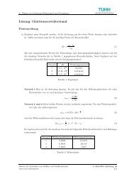
importance of each po<strong>in</strong>t was related to its pressure coefficient and the lower is this coefficient the<br />
more important is the po<strong>in</strong>t, we chose the follow<strong>in</strong>g fitness function:<br />
F<br />
δ<br />
b<br />
( d)<br />
= ∑ G(<br />
s)<br />
i<br />
C<br />
i<br />
P<br />
(3.1)<br />
where the sum is over the work<strong>in</strong>g po<strong>in</strong>ts δ b is 1 if the po<strong>in</strong>t is <strong>in</strong>side the bucket, otherwise:<br />
d<br />
⎛ 1 ⎞<br />
e − ⎜1<br />
+ ⎟<br />
( )<br />
⎝ d<br />
δ<br />
⎠<br />
b<br />
d =<br />
(3.2)<br />
e −1<br />
where d is the distance from the border of the bucket. This function was <strong>in</strong>troduced not to rise the<br />
penalty of airfoil whose bucket was very close to the work<strong>in</strong>g po<strong>in</strong>ts but not large enough to hold<br />
them all. F<strong>in</strong>ally, as thickness is a mandatory requirement <strong>in</strong> airfoil design <strong>in</strong> order to ensure<br />
structural strength, fitness function was multiplied by a narrow band Gaussian function peaked<br />
around the required thickness s req. , expressed by:<br />
G(<br />
s)<br />
−( s−s ) 2<br />
req .<br />
e<br />
∝ (3.3)<br />
The result<strong>in</strong>g fitness function has been used for rank<strong>in</strong>g the chromosomes <strong>in</strong> the genetic process<br />
described <strong>in</strong> the next paragraph.<br />
4. The Genetic Algorithm<br />
Genetic Algorithms are versatile optimization algorithms based on the theory of evolution Holland<br />
(1975). Standard implementations, Goldberg (1989), code a population of P trial solutions <strong>in</strong>to b<strong>in</strong>ary<br />
str<strong>in</strong>gs called chromosomes; as the evolutive process goes on, the population characteristics improve<br />
thanks to the crossover, reproduction and mutation operators applied on chromosomes, selected<br />
accord<strong>in</strong>g to the value of a suitable fitness function. As a consequence, the best solutions spread their<br />
characteristics among the population, caus<strong>in</strong>g the fitness function calculated on the basis of<br />
population’s chromosomes to <strong>in</strong>crease; once it has reached a fixed threshold level or a maximum<br />
number of generations has been completed, the procedure is stopped.<br />
As far as our implementation is concerned, the generic trial solution on whose parameters the GA acts<br />
is represented by the follow<strong>in</strong>g expression:<br />
Φ<br />
trial<br />
=<br />
{( , θ ),0 ≤ i ≤ B −1}<br />
σ (4.1)<br />
i<br />
i<br />
19
where the couple ( σ<br />
i<br />
, θ<br />
i<br />
) conta<strong>in</strong>s the i th segment and angle of the considered trial solution, and B is<br />
the total number of couples needed for describ<strong>in</strong>g the profile. Moreover, for avoid<strong>in</strong>g the production<br />
of non-feasible solutions, constra<strong>in</strong>ts are imposed on the chromosomes parameters, and all of the P<br />
chromosomes are checked before calculat<strong>in</strong>g their fitness value. The chosen constra<strong>in</strong>ts can be<br />
expressed by these expressions:<br />
σ ∈<br />
θ ∈<br />
i<br />
i<br />
[ αm<strong>in</strong><br />
, α<br />
max<br />
]<br />
[ θ , θ ]<br />
m<strong>in</strong><br />
be<strong>in</strong>g ( α<br />
l,<br />
α<br />
u<br />
) and ( θ<br />
l,<br />
θ<br />
u<br />
) the couples describ<strong>in</strong>g the lower and upper bound for α and θ<br />
parameters, respectively.<br />
Unlike standard GAs, we directly act on the real parameters of the profile for avoid<strong>in</strong>g timeconsum<strong>in</strong>g<br />
cod<strong>in</strong>g/decod<strong>in</strong>g procedures and quantization errors deriv<strong>in</strong>g from express<strong>in</strong>g real<br />
numbers with boolean words.<br />
max<br />
(4.2)<br />
Application of<br />
GA operators<br />
Fitness<br />
Calculation<br />
Constra<strong>in</strong>ts<br />
Check<br />
Population<br />
Initialization<br />
Fitness<br />
Calculation<br />
START<br />
no<br />
Stop?<br />
yes<br />
STOP<br />
Fig.3: Flowchart of the Genetic Algorithm<br />
As usual, for the adaptation of trial solutions over the environment, chromosomes are ranked<br />
accord<strong>in</strong>g to their respective value of the fitness function expressed <strong>in</strong> formula (3.1) before genetic<br />
operators are applied.<br />
As far as the GA operators are concerned, crossover is a standard s<strong>in</strong>gle-po<strong>in</strong>t one that is applied on<br />
couples of roulette wheel-selected, Goldberg (1989), chromosomes with probability ζ C , and mutation<br />
alters each gene of every chromosome with probability ζ M by perturb<strong>in</strong>g its value <strong>in</strong> the range<br />
expressed by:<br />
α<br />
θ<br />
new<br />
i<br />
new<br />
i<br />
= rand(<br />
α<br />
= rand(<br />
θ<br />
old<br />
i<br />
old<br />
i<br />
− µ , α<br />
− µ , θ<br />
θ<br />
α<br />
old<br />
i<br />
old<br />
i<br />
+ µ )<br />
+ µ )<br />
θ<br />
α<br />
(4.6)<br />
20
where µ<br />
α<br />
and µ<br />
θ<br />
are the chosen mutation <strong>in</strong>tervals for α and θ parameters, respectively, usually<br />
set to a quarter of the whole range.<br />
The flowchart of this procedure is shown <strong>in</strong> Fig.3.<br />
5. Profile Comparison<br />
The procedure for compar<strong>in</strong>g the performances of new profiles with the orig<strong>in</strong>al one checks the<br />
position of the operat<strong>in</strong>g po<strong>in</strong>ts with respect to the cavitation bucket.<br />
Operat<strong>in</strong>g po<strong>in</strong>ts of the orig<strong>in</strong>al profile are obta<strong>in</strong>ed by the lift<strong>in</strong>g surface code that analyses the<br />
work<strong>in</strong>g conditions of each blade section that, dur<strong>in</strong>g a complete revolution, meets different <strong>in</strong>flow<br />
conditions due to the non homogeneous wake.<br />
The start<strong>in</strong>g data set is then comprised of the orig<strong>in</strong>al cavitation bucket and of the operat<strong>in</strong>g po<strong>in</strong>ts, as<br />
illustrated <strong>in</strong> the follow<strong>in</strong>g Fig.4.<br />
S<strong>in</strong>ce the <strong>in</strong>put data of Eppler’s code do not allow a direct control of the zero lift angle of the foil, the<br />
new profiles can have a considerably different zero lift angle from the orig<strong>in</strong>al one to which the<br />
operat<strong>in</strong>g po<strong>in</strong>ts refer. For this reason the orig<strong>in</strong>al operat<strong>in</strong>g po<strong>in</strong>ts can not be superimposed on the<br />
cavitation bucket of the new profiles.<br />
4<br />
3.5<br />
3<br />
2.5<br />
α<br />
2<br />
1.5<br />
A<br />
A<br />
1<br />
0.5<br />
0<br />
-0.5<br />
0 0.1 0.2 0.3 0.4 0.5 0.6 0.7 0.8 0.9 1<br />
σ<br />
Fig.4: Cavitation bucket and operat<strong>in</strong>g po<strong>in</strong>ts<br />
The fundamental design constra<strong>in</strong>t of an improved propeller design is usually the thrust value. In<br />
order to produce the same thrust, if the new blade sections have different zero lift angles they should<br />
also have different <strong>in</strong>cidence angles.<br />
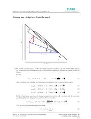
With reference to the symbols def<strong>in</strong>ed <strong>in</strong> Fig.5 and assum<strong>in</strong>g that the follow<strong>in</strong>g relations holds:<br />
CL<br />
= 2πα<br />
I<br />
to produce the same lift two different foils, at the design po<strong>in</strong>t, should have the same hydrodynamic<br />
angle of <strong>in</strong>cidence α I .<br />
21
α 0<br />
a'ωr<br />
α I<br />
α<br />
aV A<br />
ϕ<br />
β I<br />
V A<br />
ωr<br />
Fig.5: Velocity angles<br />
Assign<strong>in</strong>g subscript 1 to the quantities perta<strong>in</strong><strong>in</strong>g to the new profile the follow<strong>in</strong>g relations must hold:<br />
⎧α<br />
I<br />
= α<br />
0<br />
+ α<br />
⎨<br />
⎩α<br />
I<br />
= α<br />
01<br />
+ α<br />
the new angle of <strong>in</strong>cidence can be obta<strong>in</strong>ed from the follow<strong>in</strong>g equations:<br />
⎧α<br />
= α<br />
I<br />
−α<br />
0<br />
⎨<br />
⎩α<br />
1<br />
= α<br />
I<br />
−α<br />
Assum<strong>in</strong>g that the <strong>in</strong>duced velocities aV A and a’ωr do not change, the β I angle rema<strong>in</strong>s the same for<br />
the two profiles. It is then possible to obta<strong>in</strong> the pitch angle of the new foil section from the<br />
equations:<br />
1<br />
01<br />
⎧ ϕ = α + β<br />
I<br />
⎨<br />
⎩ϕ<br />
1<br />
= α1<br />
+ β<br />
I<br />
Bear<strong>in</strong>g <strong>in</strong> m<strong>in</strong>d that the different work<strong>in</strong>g po<strong>in</strong>ts of the section orig<strong>in</strong>ate from differ<strong>in</strong>g <strong>in</strong>flow<br />
conditions that modify the β I angle dur<strong>in</strong>g a blade revolution, variations δα with respect to the design<br />
<strong>in</strong>cidence can be computed for each angular blade position. Under the assumption that the <strong>in</strong>duced<br />
velocities are the same for the two propellers, variations δα are equal to variations δβ I<br />
The operat<strong>in</strong>g po<strong>in</strong>ts of the new blade section can then be calculated add<strong>in</strong>g the variations δα that<br />
were obta<strong>in</strong>ed for the orig<strong>in</strong>al profile to the design <strong>in</strong>cidence angle α 1 of the new blade section.<br />
22
From another po<strong>in</strong>t of view and under the same assumptions, the <strong>in</strong>cidence angles of the new<br />
operat<strong>in</strong>g po<strong>in</strong>ts can be obta<strong>in</strong>ed from the follow<strong>in</strong>g equation:<br />
α +<br />
0<br />
+ α = α<br />
01<br />
α1<br />
that implies:<br />
α<br />
( α − )<br />
1 i<br />
= α i<br />
+<br />
0<br />
α<br />
01<br />
4<br />
3.5<br />
3<br />
2.5<br />
α<br />
2<br />
1.5<br />
A<br />
B<br />
A<br />
B<br />
1<br />
0.5<br />
0<br />
-0.5<br />
0 0.1 0.2 0.3 0.4 0.5 0.6 0.7 0.8 0.9 1<br />
σ<br />
Fig.6: Profiles performance comparison<br />
The <strong>in</strong>cidence angles of the new operat<strong>in</strong>g po<strong>in</strong>ts differ from those of the orig<strong>in</strong>al profile by:<br />
( α<br />
0<br />
− α 01<br />
)<br />
The result of this operation is illustrated <strong>in</strong> Fig.6 that compares cavitation buckets ad operat<strong>in</strong>g po<strong>in</strong>ts<br />
perta<strong>in</strong><strong>in</strong>g to two profiles hav<strong>in</strong>g different zero lift angle.<br />
A procedure was developed to obta<strong>in</strong> the work<strong>in</strong>g po<strong>in</strong>ts of new profiles <strong>in</strong> order to perform a correct<br />
comparison of the performances.<br />
6. Code performance<br />
The present work orig<strong>in</strong>ated from the necessity of develop<strong>in</strong>g a tool for optimization of foil sections<br />
with regard to cavitation. To this effect, a fitness function was designed <strong>in</strong> order to compare different<br />
solutions <strong>in</strong> terms of cavitation bucket. The computer code was validated on a test case for which a<br />
very good solution was already available and used as a benchmark. The code was run and it stopped<br />
after 2840 iterations.<br />
As an essential example of the code performances, a basic comparison is given here consider<strong>in</strong>g the<br />
solutions of the first iteration, of the optimum solution and of the benchmark. Fig.7 illustrates the<br />
cavitation buckets and the relevant operat<strong>in</strong>g po<strong>in</strong>ts of the profiles of the first iteration, of the<br />
23
optimum solution and of the benchmark.<br />
4.5<br />
4<br />
3.5<br />
3<br />
α<br />
2.5<br />
2<br />
1.5<br />
Benchmark<br />
First<br />
Optimum<br />
B<br />
F<br />
O<br />
1<br />
0.5<br />
0<br />
-0.5<br />
0.25 0.35 0.45 0.55 0.65<br />
σ<br />
Fig.7: Benchmark results – cavitation buckets comparison<br />
The performance of the first iteration is clearly totally unacceptable s<strong>in</strong>ce none of the operat<strong>in</strong>g po<strong>in</strong>ts<br />
falls <strong>in</strong>side the relevant cavitation bucket. The optimum solution compares very well with the<br />
benchmark. The optimum section is better than the benchmark <strong>in</strong> terms of lam<strong>in</strong>ar cavitation s<strong>in</strong>ce its<br />
bucket comprehends a work<strong>in</strong>g po<strong>in</strong>t that is out of the bucket of the benchmark. Conversely the<br />
optimum section is slightly poorer than the benchmark <strong>in</strong> terms of bubble cavitation s<strong>in</strong>ce one of the<br />
operat<strong>in</strong>g po<strong>in</strong>ts is outside its bucket.<br />
Rigorously speak<strong>in</strong>g, the benchmark section is better than the optimum s<strong>in</strong>ce bubble cavitation is<br />
worse than lam<strong>in</strong>ar cavitation. Consider<strong>in</strong>g the fitness function that was used for the optimization, the<br />
optimum section is better than the benchmark s<strong>in</strong>ce the external po<strong>in</strong>t is nearer to the bucket<br />
boundary. This problem can easily be solved add<strong>in</strong>g some penalty to the po<strong>in</strong>ts that are out of the<br />
bucket <strong>in</strong> the region of bubble cavitation. Fig.8 reproduces the shape of the considered sections. As it<br />
can be observed, the geometry of the optimum solution is similar to that of the benchmark;<br />
notwithstand<strong>in</strong>g the fact that the fitness function did not <strong>in</strong>clude any control on the section shape<br />
other that the thickness, the algorithm does not produce “creative” solutions.<br />
The code performs very well also <strong>in</strong>creas<strong>in</strong>g the number of parameters of the problem. Figs.9 and 10<br />
compare between optimum solutions obta<strong>in</strong>ed with four and six pairs of parameters (arc percentage,<br />
angle).<br />
7. Results and conclusions<br />
The use of a code which requires complex <strong>in</strong>put takes a lot of time and several calculations must be<br />
attempted reach the optimum result. Besides, <strong>in</strong>put data need to be checked prevent the code from<br />
crash<strong>in</strong>g. Computer programs such as Eppler’s are not user friendly and require considerable<br />
experience by the user to get mean<strong>in</strong>gful results, s<strong>in</strong>ce <strong>in</strong>put parameters are not directly correlated<br />
with the shape of the resultant foil section. For this reason a high effort is required from the user if the<br />
design of a high performance profile is attempted.<br />
24
Y<br />
X<br />
Benchmark First Optimum<br />
Fig.8: Benchmark results – foil section geometry<br />
4.5<br />
4<br />
3.5<br />
3<br />
α<br />
2.5<br />
2<br />
1.5<br />
Benchmark<br />
Opti 4<br />
Opti 6<br />
B<br />
O 4<br />
O 6<br />
1<br />
0.5<br />
0<br />
-0.5<br />
0.25 0.35 0.45 0.55 0.65<br />
σ<br />
Fig.9: Comparison of performances of optimum solutions with 4 and 6 pairs of parameters<br />
25
The most <strong>in</strong>terest<strong>in</strong>g feature of the proposed approach is that only some marg<strong>in</strong>al parameters of <strong>in</strong>put<br />
must be chosen by the user and these data are ma<strong>in</strong>ly related to numerical procedures used by the<br />
code, while hydrodynamics parameter, namely the arc limits and angles of attack, the beg<strong>in</strong>n<strong>in</strong>g of<br />
pressure recovery region and of closure contribution <strong>in</strong> the upper and lower side of the profile are<br />
completely controlled by the GA. In this way also an <strong>in</strong>experienced user can profit from the capability<br />
of computer programs such as Eppler’s.<br />
Y<br />
X<br />
Benchmark Opti 4 Opti 6<br />
Fig.10: Section geometry of optimum solutions with 4 and 6 pairs of parameters<br />
The GA let the designer to run several thousands of tests per hour also on a small PC and this assures<br />
a wide <strong>in</strong>vestigation over the possible solutions. Furthermore, the results can be conditioned by more<br />
complex fitness functions def<strong>in</strong>ed by the designer accord<strong>in</strong>g to the particular needs of the problem.<br />
The consistency of the results is assured by the profile comparison that is performed tak<strong>in</strong>g <strong>in</strong>to<br />
account the differences <strong>in</strong> zero lift angles.<br />
References<br />
EPPLER, R.; SOMERS, D.M. (1980), Supplement to: A computer program for the design and<br />
analysis of low-speed airfoils, NASA TM 81862<br />
KUIPER, G.; JESSUP, S.D. (1993), A propeller design method for unsteady conditions, SNAME<br />
Trans. Vol. 101, pp.247-273<br />
KIRKPATRICK, S.; GELATT JR., C.D.; VECCHI, M.P. (1983), Optimization by simulated<br />
anneal<strong>in</strong>g, Science, 220, 4598, pp.671-680<br />
HOLLAND, J.H. (1975), Adaptation <strong>in</strong> natural and artificial systems, MIT Press<br />
GOLDBERG, D.E. (1989), Genetic algorithms <strong>in</strong> search, optimization, and mach<strong>in</strong>e learn<strong>in</strong>g,<br />
Addison-Wesley<br />
26
A Systematic Study on Pos<strong>in</strong>g and Solv<strong>in</strong>g<br />
the Problem of Pareto Optimal Ship Rout<strong>in</strong>g<br />
Jörn H<strong>in</strong>nenthal, TU Berl<strong>in</strong>, Berl<strong>in</strong>/Germany, h<strong>in</strong>nenthal@ism.tu-berl<strong>in</strong>.de<br />
Stefan Harries, FRIENDSHIP – Systems, Harries@FRIENDSHIP-Systems.com<br />
Abstract<br />
The paper proposes an optimization approach to select<strong>in</strong>g the most advantageous route on the basis<br />
of hydrodynamic simulations. An elaborated example is given for an <strong>in</strong>tercont<strong>in</strong>ental conta<strong>in</strong>er<br />
service (CMS Hannover Express) between Europe (Le Havre) and North-America (New York).<br />
Different weather situations for the North Atlantic are taken <strong>in</strong>to account. Time loss, fuel<br />
consumption, accelerations and slamm<strong>in</strong>g are m<strong>in</strong>imized on the basis of several performance models<br />
– for <strong>in</strong>stance response amplitude operators for the ship’s motions. The routes <strong>in</strong> adverse weather<br />
conditions are established as perturbations to a parent route <strong>in</strong> calm weather which is assumed to be<br />
the concatenated great circles between way po<strong>in</strong>ts. Utiliz<strong>in</strong>g a B-spl<strong>in</strong>e technique, the number of free<br />
variables for describ<strong>in</strong>g both the course and the velocity profile is kept low. For solv<strong>in</strong>g the multiobjective,<br />
non-l<strong>in</strong>ear and constra<strong>in</strong>ed optimization problem the commercial package mode-<br />
FRONTIER has been successfully applied. Investigations utiliz<strong>in</strong>g various objective functions serve to<br />
adopt a Multi-Objective Genetic Algorithm (MOGA) to automatically fill up a solution space of<br />
feasible routes for the support of the decision-mak<strong>in</strong>g process.<br />
1. Introduction<br />
Sophisticated rout<strong>in</strong>g of ships is <strong>in</strong>creas<strong>in</strong>gly recognized as an important contribution to safe, reliable<br />
and economic ship operations. The more accurate both weather forecasts and performance simulations<br />
of ships <strong>in</strong> a seaway become, the better they serve to identify the best possible route.<br />
An optimum route complies with the desired time of arrival at m<strong>in</strong>imum fuel consumption and<br />
maximum safety. Permissible and reasonable loads on the ship, the cargo and the crew are not<br />
allowed to be exceeded. This establishes a multi-objective, non-l<strong>in</strong>ear and constra<strong>in</strong>ed optimization<br />
problem <strong>in</strong> which a suitable compromise is to be found between oppos<strong>in</strong>g targets.<br />
2. Wave data<br />
While the estimated time of arrival (ETA) and fuel consumption (FUEL) depend on all environmental<br />
conditions, accelerations and slamm<strong>in</strong>g are primarily <strong>in</strong>fluenced by swell. Swell - i.e., long-crested<br />
waves - be<strong>in</strong>g the crucial factor, we decided to focus on this <strong>in</strong>fluence, leav<strong>in</strong>g out w<strong>in</strong>d-sea, current,<br />
w<strong>in</strong>d, drift-ice, shallow-water etc. for later and more ref<strong>in</strong>ed work. The objective therefore was to<br />
suggest a novel approach to rout<strong>in</strong>g and to <strong>in</strong>vestigate its merits without claim<strong>in</strong>g completeness of the<br />
model. It will be shown, however, that an extension of the optimization scheme is rather straightforward,<br />
allow<strong>in</strong>g to quickly <strong>in</strong>corporate ref<strong>in</strong>ed analyses.<br />
The wave data used were provided by the European Centre of Medium-Range Weather Forecast<br />
(ECMWF). They are a h<strong>in</strong>d cast of the sea conditions <strong>in</strong> the North Atlantic <strong>in</strong> the periods from 6. to<br />
16. of June 2001 (calm sea condition), 20. to 30. of January 2002 (rough sea condition) and 1. to 11.<br />
of January 2003 (<strong>in</strong>termediate sea condition) and are based on a reanalysis of buoy- and satellite<br />
measurements. The data for the significant wave height H 1/3 , the peak period T P and the wave angle β<br />
are given <strong>in</strong> time steps of 12 hours on a grid with 1.5° mesh size. With<strong>in</strong> the route optimization these<br />
data were treated as if they had been a wave forecast.<br />
To obta<strong>in</strong> a cont<strong>in</strong>uous wave energy spectrum as a function of the wave frequency the data were<br />
associated with the description of a Bretschneider wave spectrum, cp. Lewis (1998):<br />
27
2<br />
172.8 ⋅H<br />
1<br />
⎪⎧<br />
⎪⎫<br />
−5<br />
− 691.2<br />
3<br />
−4<br />
S<br />
ζ<br />
( ω)<br />
=<br />
⋅ω ⋅ exp ⎨ ⋅ ω<br />
4<br />
4 ⎬<br />
(1)<br />
T1<br />
⎪⎩ T1<br />
⎪⎭<br />
ω<br />
p<br />
(2001).<br />
2 π<br />
= , the modal frequency, T1 = 0. 772 ⋅Tp<br />
, transformation from mean to peak period, Journée<br />
T<br />
p<br />
3. Ship responses <strong>in</strong> waves<br />
Response amplitude operators (RAOs) and response functions for the added resistance due to waves<br />
(RFs) were employed for the evaluation of the ship performance <strong>in</strong> waves. Both have been calculated<br />
prior to the optimization by means of the strip theory code SEAWAY, Journée (2001), based on<br />
potential theory. Besides RAOs for the center of gravity motions for all six degrees of freedom and<br />
RAOs for the motions of selected po<strong>in</strong>ts also relative to the free surface, two different methods are<br />
available to determ<strong>in</strong>e the added resistance due to waves: The radiated energy method of Gerritsma<br />
and Beukelman and the <strong>in</strong>tegrated pressure method of Boese, Journée (2001).The numerical results<br />
used with<strong>in</strong> the optimization procedure are:<br />
• The RAOs of the translatory motions on the bridge (calculation of the load<strong>in</strong>g on the crew by<br />
means of accelerations).<br />
• The RAOs of the motion relative to the free surface (calculation of the slamm<strong>in</strong>g probability).<br />
• The RFs for the added resistance due to waves (preferably accord<strong>in</strong>g to the <strong>in</strong>tegrated<br />
pressure method which displays a smoother distribution over the wave frequency ω than its<br />
radiated energy counterpart).<br />
Fig.1 shows the RAOs of motion on the bridge, relative motion at the bow and the RFs of the added<br />
resistance due to waves as computed with SEAWAY. The plots serve to illustrate the <strong>in</strong>put to the<br />
response simulations with<strong>in</strong> the route optimization.<br />
3.1. Ship motions<br />
Fig.1: RAOs of motion on the bridge, relative motion at the bow<br />
and the RFs of the added resistance due to waves<br />
The product of the wave spectrum S ζ and a squared RAO of the considered motion yields the response<br />
spectrum of the ship motion S s :<br />
( ω) = RAO ⋅S<br />
( ω)<br />
S s<br />
2<br />
ζ<br />
(2)<br />
Tak<strong>in</strong>g <strong>in</strong>to account the ship velocity, this operation has to be performed with all <strong>in</strong>volved terms<br />
28
expressed as functions of the wave encounter frequency ω e . Generally the n th moment of the response<br />
spectrum is built with:<br />
∞<br />
∫<br />
∞<br />
n<br />
( ω<br />
e<br />
) ⋅ω<br />
e<br />
dω<br />
e=<br />
∫ Ss( ω )<br />
mn s<br />
= Ss<br />
⋅ω<br />
e<br />
dω<br />
(3)<br />
0<br />
0<br />
n<br />
The significant amplitude of the acceleration is determ<strong>in</strong>ed with the follow<strong>in</strong>g approximate formula<br />
provided by probability calculations:<br />
& (4)<br />
1 = ⋅<br />
3<br />
sa 2.0 m4<br />
s<br />
This can be applied to determ<strong>in</strong>e the acceleration on the bridge for <strong>in</strong>stance.<br />
3.2. Slamm<strong>in</strong>g<br />
Slamm<strong>in</strong>g can be def<strong>in</strong>ed as the co<strong>in</strong>cidence of two events: the emergence of the bow and its<br />
subsequent dunk<strong>in</strong>g above a critical velocity. The critical velocity accord<strong>in</strong>g to Ochi, Journée (2001),<br />
is:<br />
s& = 0.<br />
0928 ⋅ g ⋅L<br />
(5)<br />
cr<br />
pp<br />
Presum<strong>in</strong>g statistical <strong>in</strong>dependence of these events the probability of slamm<strong>in</strong>g is calculated from:<br />
P<br />
{ slam}<br />
⎪⎧<br />
−D<br />
= exp ⎨<br />
⎪⎩ 2 m0<br />
2<br />
s rel<br />
−s&<br />
+<br />
2 m<br />
2<br />
cr<br />
2srel<br />
⎪⎫<br />
⎬<br />
⎪⎭<br />
(6)<br />
Where m 0srel and m 2srel are the 0 th and 2 nd moment, respectively, of the response spectrum for a po<strong>in</strong>t<br />
on the keel l<strong>in</strong>e 10% beh<strong>in</strong>d the forward perpendicular FP, D be<strong>in</strong>g the draught 10% beh<strong>in</strong>d FP.<br />
3.3. Fuel consumption<br />
The added resistance due to waves is calculated from:<br />
∞<br />
∫<br />
0<br />
ζ<br />
( ω )<br />
R AW<br />
= RF ⋅S<br />
dω<br />
(7)<br />
The determ<strong>in</strong>ation of the calm water resistance is based on a regression analysis of model tests and<br />
full-scale data, follow<strong>in</strong>g Holtrop and Mennen (1984).The operat<strong>in</strong>g po<strong>in</strong>t of the propeller was<br />
calculated accord<strong>in</strong>g to the ITTC (1978) power prediction method, us<strong>in</strong>g the characteristic of a<br />
propeller with the same diameter, number of blades, similar pitch and blade area ratio as given <strong>in</strong><br />
Yasaki (1962). In a f<strong>in</strong>al step the fuel consumption and the compliance with the permitted operat<strong>in</strong>g<br />
condition was determ<strong>in</strong>ed <strong>in</strong> agreement with the project guide available from the producer of the<br />
ship's ma<strong>in</strong> eng<strong>in</strong>e, MAN B&W (2000).<br />
4. Sett<strong>in</strong>g up of the optimization task<br />
Simply put, automated optimization is the formal process of f<strong>in</strong>d<strong>in</strong>g a good (the best) solution from a<br />
set of feasible alternatives. It requires a complete mathematical problem formulation <strong>in</strong> terms of<br />
objective functions (what is to be improved), free variables (what shall be consciously changed) and<br />
constra<strong>in</strong>ts (what restricts the feasibility).<br />
29
4.1. Free Variables<br />
To provide free variables for both the spatial and the temporal description of the route the path and the<br />
velocity profile were given as B-spl<strong>in</strong>es. Perturbations of a parent route <strong>in</strong> time and space were<br />
realized by superpos<strong>in</strong>g the appropriate parent spl<strong>in</strong>e with a Greville-spaced shift spl<strong>in</strong>e. The vertices<br />
of the shift spl<strong>in</strong>es are controlled by shift parameters that were taken as the free variables of the<br />
optimization task.<br />
The velocity perturbation was performed as a reduction of the design speed of 23kn. The spatial<br />
perturbation provides a shift of maximum 10% of the arc length of the orig<strong>in</strong>al parent route to either<br />
starboard or port.<br />
Fig.2 presents example routes as realized with 5 parameters for the spatial shift. The optimization was<br />
focused on the open water part of the journey, pilot time and estuary travel<strong>in</strong>g was deliberately left<br />
out of the <strong>in</strong>vestigation. The geographical feasibility was checked dur<strong>in</strong>g the optimization process.<br />
4.2. Constra<strong>in</strong>ts<br />
Fig.2: parent route, perturbation and <strong>in</strong>vestigated area<br />
Constra<strong>in</strong>ts were imposed by def<strong>in</strong><strong>in</strong>g limit<strong>in</strong>g values for the slamm<strong>in</strong>g probability (3%) and for the<br />
lateral and vertical accelerations (0.2 g, g = 9.807 m/s 2 ).<br />
4.3. Objectives<br />
Two major objectives, the estimated time of arrival (ETA) and the fuel consumption (FUEL), were<br />
taken <strong>in</strong>to account both of which had to be m<strong>in</strong>imized. Especially <strong>in</strong> rough weather conditions <strong>in</strong>itial<br />
route variants need to be quiet slow to avoid <strong>in</strong>feasibility due to active constra<strong>in</strong>ts. The follow<strong>in</strong>g<br />
objective functions were used to accelerate the propagation of the <strong>in</strong>itial routes towards faster route<br />
variants <strong>in</strong> the multi-objective optimization:<br />
Objective<br />
ETA<br />
( ETA − set value ETA) 2<br />
= , (8)<br />
⎛<br />
ETA ⎞<br />
Objective FUEL = weight ⋅<br />
⎜ FUEL − FUEL ⋅<br />
⎟ . (9)<br />
⎝<br />
set value ETA ⎠<br />
The set value of ETA was derived from optimum results at calm water conditions (ETA = 114 hours<br />
after departure, the value matches the estimated duration of a journey as stated <strong>in</strong> the sail<strong>in</strong>g lists of<br />
the ship operator; the weight assigned to the FUEL objective was 0.05, so as to produce objectives of<br />
an equal magnitude at the biggest deviants of the set value).<br />
2<br />
30
4.4. Optimization with modeFRONTIER<br />
For the optimization task the generic optimization software modeFRONTIER was utilized,<br />
www.esteco.it. The process flow <strong>in</strong> Fig.3 can be read from left to right. Initially, the free variables<br />
used as <strong>in</strong>put parameter of the optimization loop are collected <strong>in</strong> an <strong>in</strong>put file (parameter.txt).<br />
Afterwards an application is started to build the new route by means of a perturbation of the parent<br />
route accord<strong>in</strong>g to the actual <strong>in</strong>put parameter (makeroute). Next, the route is evaluated (virtualShip)<br />
and results are given back to modeFRONTIER. F<strong>in</strong>ally, the optimization rout<strong>in</strong>e observes the<br />
constra<strong>in</strong>ts, calculates the objectives and, if necessary, launches a new <strong>in</strong>vestigation. The optimization<br />
results presented <strong>in</strong> the follow<strong>in</strong>g chapters belong to a westbound Atlantic cross<strong>in</strong>g of the Hapag<br />
Lloyd panmax conta<strong>in</strong>er vessel “CMS Hannover Express”.<br />
Fig.3: modeFRONTIER flow chart<br />
5. Optimization results at different weather conditions<br />
Two different search strategies, a SIMPLEX and a multi-objective genetic algorithm MOGA, were<br />
applied. Both, SIMPLEX and MOGA optimizations were conducted for a calm, a rough and an<br />
<strong>in</strong>termediate weather situation. S<strong>in</strong>ce the SIMPLEX algorithm can handle only one objective,<br />
optimizations were constricted to the m<strong>in</strong>imization of ETA. With<strong>in</strong> MOGA the m<strong>in</strong>imization of both<br />
ETA and FUEL was undertaken.<br />
Fig.4 shows the result of a MOGA optimization <strong>in</strong> rough sea conditions. Each square represents a<br />
feasible route that can be taken <strong>in</strong>to account for a route decision consider<strong>in</strong>g ETA and FUEL. The<br />
solution space is bordered by a Pareto frontier – the set of all solutions for which a s<strong>in</strong>gle objective<br />
cannot be further improved without deteriorat<strong>in</strong>g any other objective. All routes lie above and to the<br />
right of the Pareto frontier. Those variants that are closest to the frontier display low passage time for<br />
reasonably low fuel consumption. Apparently, it is impossible to decrease ETA below certa<strong>in</strong> limits<br />
without impair<strong>in</strong>g FUEL.<br />
Fig.5 illustrates the operation of a SIMPLEX optimization under rough sea condition. Start<strong>in</strong>g from a<br />
set of <strong>in</strong>itial designs at a low speed level the optimization converged to a local optimum. None of the<br />
routes touch the Pareto frontier found by the genetic algorithm. The figure nicely shows the limitation<br />
of a determ<strong>in</strong>istic search strategy like the SIMPLEX algorithm. As a general rule it is difficult to<br />
identify a global optimum and the search goes quickly to the (nearest) local optimum. While<br />
neglect<strong>in</strong>g FUEL an agreement of the optimization result with the Pareto frontier should therefore not<br />
31
e expected. Further <strong>in</strong>vestigations with different start<strong>in</strong>g po<strong>in</strong>ts and objective functions depend<strong>in</strong>g on<br />
both ETA and FUEL achieved no improvement.<br />
Table 1 and Fig.6 compare SIMPLEX and MOGA optimization results at different sea conditions.<br />
The time m<strong>in</strong>imum routes of the SIMPLEX and Pareto routes of the MOGA are depicted. For the<br />
genetic algorithm 7000 route variants were <strong>in</strong>vestigated (one population consists of 70 <strong>in</strong>dividuals,<br />
100 generations). The SIMPLEX converged most of the time with less than 400 iterations but never<br />
matched the time m<strong>in</strong>imum route found by MOGA. An advantage of the SIMPLEX is time sav<strong>in</strong>g<br />
due to smaller computational effort. The MOGA, however, is capable to fill up the solution space, to<br />
identify a Pareto frontier and therefore to provide a mean<strong>in</strong>gful data base for the rout<strong>in</strong>g decision<br />
support. Each route presented by a square <strong>in</strong> Fig.4 can be selected and taken <strong>in</strong>to account for the<br />
decision mak<strong>in</strong>g of the naval officer consider<strong>in</strong>g ETA and FUEL. But also <strong>in</strong>dividual preferences<br />
concern<strong>in</strong>g slamm<strong>in</strong>g probability or allowable accelerations can be regarded. Consequently a more<br />
conscious decision can be made about which route to take. Sometimes this will yield fuel sav<strong>in</strong>gs for<br />
arriv<strong>in</strong>g at the desired time. Sometimes this will show which route is still the best (or least worse) for<br />
severe conditions. Furthermore, only the MOGA found the shortest route at calm sea condition<br />
(although maximum significant wave heights of about 5 meters occurred dur<strong>in</strong>g the cross<strong>in</strong>g, the<br />
constra<strong>in</strong>ts for slamm<strong>in</strong>g and accelerations did not affect the optimization as they all turned out to be<br />
<strong>in</strong>active, therefore the time m<strong>in</strong>imum route has to be the shortest one).<br />
Fig.6 nicely shows the <strong>in</strong>fluence of the sea condition to the m<strong>in</strong>imum atta<strong>in</strong>able ETA. In rough<br />
weather an arrival on schedule was impossible. The different fuel consumptions were caused by the<br />
ship speed, the necessary distance of the journey to avoid severe weather conditions and also the<br />
added resistance due to waves.<br />
Fig.7 illustrates four steps of an example route <strong>in</strong> rough weather, here with lowest ETA (143h). The<br />
contour l<strong>in</strong>es represent the current significant wave height dur<strong>in</strong>g the cross<strong>in</strong>g, the route and the actual<br />
position of the ship (a dot at the end of the bold black l<strong>in</strong>e) are drawn, too. The decrease of fuel<br />
consumption <strong>in</strong> comparison to the optimum route at calm sea condition is caused by low ship speeds<br />
dur<strong>in</strong>g the first 50 hours (below 18kn). From an optimization po<strong>in</strong>t of view this was necessary to let a<br />
wave field, cross<strong>in</strong>g the route from south to north, pass (first picture of Fig.7). The fuel sav<strong>in</strong>gs due to<br />
the reduced velocity exceeded the additional fuel consumption due to waves and due to a longer<br />
distance of the journey.<br />
Fig.4: MOGA results and Pareto frontier<br />
32
Fig.5: SIMPLEX optimization and Pareto frontier obta<strong>in</strong>ed by MOGA<br />
Table 1: time m<strong>in</strong>imum routes for different optimization strategies and sea conditions<br />
ETA<br />
FUEL<br />
distance design number<br />
MOGA<br />
SIMPLEX<br />
calm sea condition<br />
114 h 696 t 118 h 624 t<br />
2716 nm 7000 2722 nm 392<br />
<strong>in</strong>termediate sea condition<br />
119 h 686 t 121 h 713 t<br />
2717 nm 7000 2789 nm 302<br />
rough sea condition<br />
143 h 639 t 147 h 633 t<br />
2756 nm 7000 2813 nm 368<br />
Fig.6: MOGA Pareto designs and time m<strong>in</strong>imum routes obta<strong>in</strong>ed by SIMPLEX<br />
33
6. Summary and conclusions<br />
Fig.7: Optimized route, ETA = 143 h, fuel consumption 639 t<br />
Initially the paper provides a brief <strong>in</strong>troduction <strong>in</strong>to the mathematical description of a ship <strong>in</strong> waves<br />
used with<strong>in</strong> the presented route optimization. A new approach for the spatial and temporal generation<br />
of design variants based on parametric curves has been presented. Investigations concern<strong>in</strong>g the<br />
number of free variables showed that at least 9 variables for the description of the velocity profile and<br />
7 variables to describe the course are necessary to obta<strong>in</strong> a sufficient temporal and spatial resolution<br />
of the route that correlates to the wave pattern as well as to the geographical conditions <strong>in</strong> the North<br />
Atlantic. The chosen B-spl<strong>in</strong>e description turned out to be a reliable method for the set-up of the route<br />
optimization task. The major advantage of parametrically modeled route- and velocity profiles lies <strong>in</strong><br />
the reduced number of free variables. This enables the application of a stochastic algorithm with a<br />
reasonable time exposure.<br />
Comparative <strong>in</strong>vestigations with different optimization methods showed that the algorithm must be<br />
able to avoid a premature stop at local optima. Two strategies, the determ<strong>in</strong>istic SIMPLEX and the<br />
stochastic MOGA were utilized here. With the MOGA one may identify mean<strong>in</strong>gful optima. (Other<br />
strategies, for <strong>in</strong>stance simulated anneal<strong>in</strong>g, might also be considered but were beyond the scope of<br />
this study.) The decision mak<strong>in</strong>g of the naval officer is supported by build<strong>in</strong>g up a significant amount<br />
of <strong>in</strong>formation from which the best compromise (Pareto optimum) can be found <strong>in</strong> accordance with<br />
<strong>in</strong>dividual preferences. A further aspect that should be kept <strong>in</strong> m<strong>in</strong>d <strong>in</strong> the future is the probabilistic<br />
character of the weather and its forecast, Hoffschildt et al. (1999). As the optimized routes are guided<br />
closely along areas of rough sea condition, Fig.7, the reliability of the forecast has to be <strong>in</strong>cluded <strong>in</strong>to<br />
the evaluation of the optimization results and robustness ought to be taken <strong>in</strong>to account.<br />
Acknowledgement<br />
The work presented here was substantially facilitated and improved by Oyv<strong>in</strong>d Saetra of the European<br />
Centre of Medium Range Weather Forecast, Read<strong>in</strong>g, UK, who provided w<strong>in</strong>d and wave data.<br />
Furthermore, some of the work reported here was supported by the European Project SEAROUTES,<br />
G3RD-CT-2000-00309.<br />
34
References<br />
HOFFSCHILDT, M.; BIDLOT, J-R..; HANSEN, B.; JANSSEN, P.A.E.M. (1999), Potential benefit<br />
of ensemble forecast for ship rout<strong>in</strong>g, ECMWF Techn. Memo. 287, Internal Report, ECMWF,<br />
Read<strong>in</strong>g/UK<br />
HOLTROP, J.; MENNEN, G.G.J. (1984), An approximate power prediction method, International<br />
Shipbuild<strong>in</strong>g Progress, Vol. 31<br />
ITTC (1978), Performance prediction method for s<strong>in</strong>gle screw ships, 15th Int. Tow<strong>in</strong>g Tank Conf.,<br />
The Hague<br />
JOURNEÉ, J.M.J. (2001), User and Theoretical Manual of SEAWAY, Rel. 4.19, TU Delft<br />
MAN B&W (2000), K90MC MK6 Project Guide Two-stroke Eng<strong>in</strong>es, 5th Edition, www.manbw.dk<br />
LEWIS, E.V. (Ed.) (1998), Pr<strong>in</strong>ciples of Naval Architecture - Motions <strong>in</strong> Waves and Controllability,<br />
SNAME, Jersey City<br />
YASAKI, A. (1962), Design diagrams for modern four, five, six and seven-bladed propellers<br />
developed <strong>in</strong> Japan, 4 th Naval Hydrodynamics Symp.<br />
35
Concurrent Eng<strong>in</strong>eer<strong>in</strong>g through the Supply Cha<strong>in</strong><br />
from Ship Owner to Supplier<br />
Otto Millbourn, Tribon Solutions, Malmö/Sweden, otto.millbourn@tribon.com<br />
Abstract<br />
Efficient shipyards of today use a 3D Product Information Model as the ma<strong>in</strong> backbone for their<br />
design, plann<strong>in</strong>g and production. In 2000, TRIBON Solutions AB released Tribon.com, an Internet<br />
based, searchable shipbuild<strong>in</strong>g component database. The database conta<strong>in</strong>s searchable and<br />
structured <strong>in</strong>formation and 3D models of shipbuild<strong>in</strong>g equipment.Tribon.com br<strong>in</strong>gs the supplier<br />
closer to the design process of the yard and makes collaborative eng<strong>in</strong>eer<strong>in</strong>g possible. The idea to<br />
complete the supply cha<strong>in</strong> and <strong>in</strong>clude the ship owners comes naturally. Today the communication<br />
dur<strong>in</strong>g the new build<strong>in</strong>g process is often cumbersome and costly. The most expensive option, on site<br />
<strong>in</strong>spections, is used to a great extent. The new process offers an <strong>in</strong>tegration of the Product<br />
Information Model and Tribon.com. It enables the ship owner to monitor the design and progress of<br />
the new build<strong>in</strong>g via the Internet. The ship owner will be able to comment on the design, follow up<br />
milestones, simulate operations, and get sufficient <strong>in</strong>formation on equipment - <strong>in</strong> real time. Some ship<br />
owners and yards already test the new process. The benefits for all stakeholders are substantial: less<br />
rework, fewer man-hours spent, fewer misunderstand<strong>in</strong>gs, <strong>in</strong>creased onboard safety and others. The<br />
next step is for the ship owner to use the Product Information Model and Tribon.com to decrease the<br />
life-cycle cost.<br />
1. Introduction<br />
Today shipyards and ship owners communicate <strong>in</strong> different ways <strong>in</strong> the new build<strong>in</strong>g process (usually<br />
after the order is signed). The communication is extensive and relatively unstructured. The yards<br />
communicate with classification societies, suppliers and owners. The methods are fax, e-mail and<br />
ord<strong>in</strong>ary “snail mail”. In most cases, the documentation is sent as paper-based 2d draw<strong>in</strong>gs and<br />
specifications. Due to old traditions and the competitive situation among various suppliers, the<br />
<strong>in</strong>dividual supplier tends to reveal its technical and commercial “features” at “as-late-as-possible”<br />
stage. In addition, the owner communicates <strong>in</strong>ternally between staff on the build<strong>in</strong>g site and the head<br />
office.<br />
The communication and all the papers/documents are a problem for both the yards and the owners<br />
because of misunderstand<strong>in</strong>gs <strong>in</strong> 3D to 2D conversions and the extent of the <strong>in</strong>formation. This<br />
problem has been expressed by a number of yards and owners: Could we give access to the PIM via<br />
Internet, could Tribon.com be one <strong>in</strong>formation channel? The current process is costly and<br />
cumbersome.<br />
2. Tribon components<br />
2.1. Digital Product Model<br />
A product model can be regarded as a comprehensive “Ship Database” conta<strong>in</strong><strong>in</strong>g all relevant<br />
<strong>in</strong>formation about a specific ship. The Tribon Product Information Model is object-oriented <strong>in</strong> the<br />
sense that all design and production data are stored and handled as objects. These objects represent all<br />
of the types of physical items found <strong>in</strong> shipbuild<strong>in</strong>g (systems, components, assemblies, pipes,<br />
equipment, cables, plates, stiffeners etc.). The description of each object type is formulated such as to<br />
conta<strong>in</strong> all the necessary technical data and/or properties required for the description of a particular<br />
<strong>in</strong>stance of the object. The technical data and properties are then used to derive the graphical<br />
representation of the object for use <strong>in</strong> symbolic sketches or <strong>in</strong> 2D or 3D views, depend<strong>in</strong>g on the<br />
presentation context. When design modifications become necessary this technical data is changed<br />
rather than the graphical <strong>in</strong>formation, which would be the case <strong>in</strong> most general purpose CAD systems.<br />
36
2.2. Tribon Product Information Model<br />
The Tribon Product Information Model (PIM) (and the related software, the Tribon System) plays the<br />
role of the central tool for design, eng<strong>in</strong>eer<strong>in</strong>g and material requirements def<strong>in</strong>ition <strong>in</strong> the shipyards.<br />
S<strong>in</strong>ce all product-related data is stored <strong>in</strong> one place (the PIM) it also works as the “hub” for plann<strong>in</strong>g<br />
and coord<strong>in</strong>ation of the ships arrangements from a macro-perspective as well as on a detailed level.<br />
When work<strong>in</strong>g with traditional methods of draw<strong>in</strong>gs (paper draw<strong>in</strong>gs or electronically stored<br />
documents) there is no real mechanism to coord<strong>in</strong>ate the development of the arrangements simply<br />
because many of the designers work <strong>in</strong> parallel <strong>in</strong> a highly concurrent eng<strong>in</strong>eer<strong>in</strong>g environment.<br />
Different systems <strong>in</strong> the same room (compartment) are produced <strong>in</strong> different draw<strong>in</strong>gs, which creates<br />
risks of collisions <strong>in</strong> the f<strong>in</strong>al (physical) arrangement. Each avoided collision represents a substantial<br />
sav<strong>in</strong>g <strong>in</strong> terms of a lower degree of rework dur<strong>in</strong>g the assembly process. One could claim that “PIM<br />
produces better ships”. (Reports from shipyards us<strong>in</strong>g the Tribon PIM technology show 30% sav<strong>in</strong>gs<br />
<strong>in</strong> design and eng<strong>in</strong>eer<strong>in</strong>g man hours and 8% sav<strong>in</strong>gs <strong>in</strong> production man hours, compared to previous<br />
use of systems based on 2D electronic draw<strong>in</strong>gs philosophy.)<br />
The PIM<br />
• A valuable asset for ma<strong>in</strong>tenance. Equipment <strong>in</strong>formation, <strong>in</strong>formation<br />
for repair work, naval <strong>in</strong>formation ...<br />
Equipment<br />
Draft<strong>in</strong>g<br />
Initial<br />
Design<br />
Basic<br />
Design<br />
Hull Pipe Cable Structure<br />
Pipe<br />
Support<br />
Data<br />
Management<br />
Assembly<br />
Plann<strong>in</strong>g<br />
Production Manager<br />
Design Manager<br />
©Tribon Solutions<br />
08/01/<strong>2004</strong> 9<br />
Production<br />
Manager<br />
2.3. Tribon.com<br />
Tribon.com is a neutral Internet-based service for the maritime <strong>in</strong>dustry. It l<strong>in</strong>ks shipyards and mar<strong>in</strong>e<br />
equipment and system suppliers <strong>in</strong> a comprehensive and unique global network. The service revolves<br />
around a global database that conta<strong>in</strong>s technical <strong>in</strong>formation and components and equipment. By<br />
subscrib<strong>in</strong>g to the service, shipyards can access, download, and <strong>in</strong>tegrate <strong>in</strong>formation directly <strong>in</strong>to<br />
their design model. The <strong>in</strong>stant access to accurate, complete, and standardised product <strong>in</strong>formation<br />
will improve and shorten the time spent search<strong>in</strong>g for component <strong>in</strong>formation. Designers are able to<br />
reduce lead times and have global access to supplier products. This is the core functionality of<br />
Tribon.com.<br />
37
Essentials:<br />
• A neutral Internet-based service that gives <strong>in</strong>stant access to accurate, technical and updated<br />
<strong>in</strong>formation <strong>in</strong> a standard shipbuild<strong>in</strong>g format to suppliers, shipyards and design agents<br />
• Enables easy design <strong>in</strong>tegration<br />
• Conta<strong>in</strong>s data <strong>in</strong> standard formats<br />
• Is complemented by e-commerce functionality<br />
• Access <strong>in</strong>formation 24 hours a day, 365 days a year<br />
•<br />
Product Categories<br />
and Structure<br />
3D Volumes<br />
Complete<br />
Product Information<br />
Certificates<br />
Technical Spec.<br />
Attributes<br />
Tribon.com<br />
Extended Attributes<br />
Commercial &<br />
adm<strong>in</strong>istrative<br />
attributes,<br />
Product groups, ma<strong>in</strong>tenance<br />
systems, services <strong>in</strong>structions etc.<br />
Draw<strong>in</strong>gs<br />
Attachments<br />
©Tribon Solutions<br />
08/01/<strong>2004</strong> 4<br />
(Brochures,<br />
specifications<br />
diagrams etc.)<br />
Suppliers know how time consum<strong>in</strong>g and costly it is to handle <strong>in</strong>formation requests from customers<br />
and to get their components or systems specified to suit the needs of shipyards repeatedly. Tribon.com<br />
is a flexible market<strong>in</strong>g channel that allows suppliers to be <strong>in</strong> control of their <strong>in</strong>formation and update it<br />
as their products or systems develop. Through Tribon.com suppliers can also broadcast their<br />
<strong>in</strong>formation and news to designers. Tribon.com provides many possibilities for suppliers:<br />
• Access an efficient market<strong>in</strong>g and sales process<br />
• Reach eng<strong>in</strong>eers and designers at shipyards <strong>in</strong> the global shipbuild<strong>in</strong>g market, your target group<br />
• Create the <strong>in</strong>formation once - share it with their customers concurrently, ref<strong>in</strong>e it and use it many<br />
times<br />
• Improve communication, quality of data and decrease the paper trail<br />
• Get a new channel to the after-sales market<br />
• Increase customer satisfaction<br />
38
3. New Process<br />
The new process is be<strong>in</strong>g tested with several ship owners: BP, Wallenius, TOTE, and the US Navy.<br />
S<strong>in</strong>ce the functionality is not yet developed, we have simulated the work process. The communication<br />
is made via the Internet, but not yet <strong>in</strong>side Tribon.com which has to be driven side by side. The tests<br />
have concluded <strong>in</strong> the simplified process below. Also the benefits described are concluded with the<br />
help of the tests. The results from the tests were so beneficial that some of the owners have cont<strong>in</strong>ued<br />
with the simplified solution and are now us<strong>in</strong>g it <strong>in</strong> operation.<br />
Time<br />
Traditional<br />
methods<br />
Tribon.com<br />
Optimisation<br />
All eng<strong>in</strong>eer<strong>in</strong>g strives for to the “optimal design”. Often<br />
time and economy stop the eng<strong>in</strong>eer from reach<strong>in</strong>g total<br />
satisfaction, especially <strong>in</strong> commercial shipbuild<strong>in</strong>g.<br />
Research has shown that 30% of an eng<strong>in</strong>eer’s time is<br />
spent on “search<strong>in</strong>g for <strong>in</strong>formation”. Tribon.com gives the<br />
eng<strong>in</strong>eer direct access to the <strong>in</strong>formation, unlike traditional<br />
methods where he would spend too much time to search.<br />
Newbuild<strong>in</strong>g<br />
UNDINE<br />
My newbuild<strong>in</strong>g projects<br />
MS DON QUiJOTE<br />
Repair<br />
MS ANNICA<br />
MS DON QUiJOTE<br />
©Tribon Solutions<br />
08/01/<strong>2004</strong> 14<br />
The new process builds on the opportunities that the Internet gives. Ship owners log <strong>in</strong> via<br />
Tribon.com and can call up their new build<strong>in</strong>g or repair project. After choos<strong>in</strong>g project, ship owner<br />
can browse around <strong>in</strong> the 3D model and:<br />
• Check and comment the design <strong>in</strong> the model<br />
• Perform analysis, test functions (allow<strong>in</strong>g staff to “learn” the ship before it is built)<br />
• Follow up the progress of the project. By click<strong>in</strong>g different objects the user can get status on the<br />
objects. Example of status could be:<br />
1) for designs: <strong>in</strong> design, wait<strong>in</strong>g for class approval<br />
2) for equipment: supplier set, procured, on stock, assembled.<br />
3) For material produced by the yard: design approved, <strong>in</strong> production, assembled<br />
• Port staff and suppliers of port cargo equipment can use the model to test port equipment<br />
• The user is able to click equipment and if the supplier is set the user can get detailed <strong>in</strong>formation<br />
of the equipment. Tribon.com conta<strong>in</strong>s l<strong>in</strong>ks to supplier websites and e-mail addresses; so the<br />
owner can connect directly for questions and discussion.<br />
39
3. Benefits and risks<br />
Benefits for the owner <strong>in</strong> a new build<strong>in</strong>g or repair project are:<br />
1. Instead of call<strong>in</strong>g for <strong>in</strong>formation from the yard they can pick up the <strong>in</strong>formation themselves. Not<br />
hav<strong>in</strong>g to send draw<strong>in</strong>gs and other <strong>in</strong>formation will save man-hours and cost.<br />
2. This tool can improve communication with the ma<strong>in</strong> office and the onsite office reduc<strong>in</strong>g travel<br />
cost.<br />
3. The possibility to access the design dur<strong>in</strong>g the basic design stage will allow the owner better to<br />
affect the design, so that right decisions are made from the beg<strong>in</strong>n<strong>in</strong>g and costly rework could be<br />
avoided.<br />
4. Crew and other users can get familiar with the ship via Tribon, reduc<strong>in</strong>g rework and tra<strong>in</strong><strong>in</strong>g cost.<br />
5. Port staff and port equipment suppliers can use the design to test port equipment.<br />
Benefits for the yard <strong>in</strong> a new build<strong>in</strong>g or repair project are:<br />
1. Instead of send<strong>in</strong>g <strong>in</strong>formation on demand, the yard gives access to the <strong>in</strong>formation, and the<br />
owners can pick up the <strong>in</strong>formation themselves. Not hav<strong>in</strong>g to send draw<strong>in</strong>gs and other<br />
<strong>in</strong>formation will save man-hours and cost.<br />
2. Misunderstand<strong>in</strong>gs and disputes can be avoided, s<strong>in</strong>ce the yard always has access to the design.<br />
Some yards could feel that it is risky to put up the PIM on the Internet, allow<strong>in</strong>g <strong>in</strong>truders to get<br />
access to the network via the PIM and the Internet. In order to avoid this, an automatically created<br />
copy could be put on the Internet once a day. The copy could be put on a stand-alone PC with no<br />
access to the network.<br />
40
4. Conclusions and next step<br />
The new process is a step further <strong>in</strong> the usage of the PIM. The PIM conta<strong>in</strong>s <strong>in</strong>formation necessary for<br />
everybody <strong>in</strong>volved <strong>in</strong> the process of build<strong>in</strong>g a ship. With Tribon.com, Tribon allows now to<br />
distribute the already created <strong>in</strong>formation to those who need it, benefit<strong>in</strong>g all parties <strong>in</strong>volved with<br />
substantial cost sav<strong>in</strong>gs and boost<strong>in</strong>g the overall process. To emphasise the conclusion, I quote Mr.<br />
John Boylston, vice-president of new constructions at the ship owner Totem Ocean Trailer Express<br />
(TOTE), one of the early adaptors, from an article <strong>in</strong> the American ship review 2002-2003:<br />
“Therefore, taken to an optimistic extreme, little or no rework should be necessary <strong>in</strong> construction. A<br />
rule of thumb is that a dollar spent <strong>in</strong> construction is equivalent to 10 dollars when rework is required.<br />
While we push the yards to become more efficient and to reduce construction cost, this author<br />
believes there are more significant returns <strong>in</strong> tak<strong>in</strong>g the required time to design <strong>in</strong> 3D and <strong>in</strong>volv<strong>in</strong>g<br />
the owner <strong>in</strong> the process.”<br />
The natural next step is for the owner to also get access to the PIM after the ship is delivered, to use<br />
the important ma<strong>in</strong>tenance <strong>in</strong>formation <strong>in</strong> the model, to have the PIM if repair work or conversions<br />
are necessary. To use the PIM for support of the life-cycle of the ship will further cut cost for<br />
everybody <strong>in</strong>volved <strong>in</strong> the shipbuild<strong>in</strong>g bus<strong>in</strong>ess.<br />
41
Abstract<br />
An E-Commerce Platform for Eng<strong>in</strong>eer<strong>in</strong>g Services <strong>in</strong> Shipbuild<strong>in</strong>g<br />
Hans Wuttke, Potsdam Ship Model Bas<strong>in</strong> (SVA),<br />
Potsdam/Germany, wut@sva-potsdam.de<br />
Andreas Schwill, <strong>Institut</strong>e for Computer Science, University of Potsdam,<br />
Potsdam/Germany, schwill@cs.uni-potsdam.de<br />
Frank Domeyer, <strong>Institut</strong>e for Computer Science, University of Potsdam,<br />
Potsdam/Germany, domeyer@cs.uni-potsdam.de<br />
We present <strong>in</strong>termediate results of a long-term project to develop an Internet platform that offers<br />
eng<strong>in</strong>eer<strong>in</strong>g assistance <strong>in</strong> naval hydrodynamics. Customers are able to use, for <strong>in</strong>stance, prediction<br />
tools onl<strong>in</strong>e, get quotations for standard orders and may look-up the progress of larger projects.<br />
These services on demand are a natural extension of e-bus<strong>in</strong>ess. But while trad<strong>in</strong>g goods over the<br />
Internet is almost standard, offer<strong>in</strong>g eng<strong>in</strong>eer<strong>in</strong>g services shows some specifics which by now are not<br />
fully understood. They are mostly unique and consist of multiple parts, require more <strong>in</strong>formation exchange<br />
and the correspond<strong>in</strong>g order specifications are more comprehensive. This leads to problems<br />
that require new approaches and solutions <strong>in</strong> areas like application architecture, application development<br />
and <strong>in</strong>tegration, security and IT operations. This paper describes vision, development and<br />
implementation of the platform as well as experiences of customers.<br />
1. Introduction<br />
In general a shipbuild<strong>in</strong>g project <strong>in</strong>volves a large number of eng<strong>in</strong>eer<strong>in</strong>g services requir<strong>in</strong>g by 15-20%<br />
of the total cost not mention<strong>in</strong>g – <strong>in</strong> particular for <strong>in</strong>ternational contracts – the considerable costs for<br />
transactions and negotiations concern<strong>in</strong>g order specification, transfer and return of ship data, discussions<br />
of results etc. Often these costs multiply s<strong>in</strong>ce eng<strong>in</strong>eer<strong>in</strong>g services are ordered repeatedly with<br />
small changes and variations of requirements, ship plans, framework with respect to size and speed of<br />
the ship such that the overall contract spans several months.<br />
Reduc<strong>in</strong>g these costs is a major objective for all companies and <strong>in</strong>stitutions participat<strong>in</strong>g <strong>in</strong> a project.<br />
A promis<strong>in</strong>g strategy is to transfer certa<strong>in</strong> bus<strong>in</strong>ess processes on the Internet and to reduce the time<br />
needed to perform certa<strong>in</strong> services eventually aim<strong>in</strong>g at a turn-around time of 24 hours for selected<br />
standard services.<br />
Table I: Characteristics of e-commerce systems for products and services<br />
product-oriented<br />
e-commerce systems<br />
ad hoc order<strong>in</strong>g<br />
simple description and presentation of orders<br />
short-term contact between seller and buyer,<br />
often anonymously („one-click shopp<strong>in</strong>g“)<br />
different and comfortable payment functions<br />
elementary products with few attributes<br />
standardized mass-produced goods<br />
stable quality guaranteed by brand<br />
(<strong>in</strong>dependent of seller)<br />
dom<strong>in</strong>at<strong>in</strong>g paradigm: shopp<strong>in</strong>g cart<br />
e-commerce systems for<br />
eng<strong>in</strong>eer<strong>in</strong>g services<br />
<strong>in</strong>tensive exchange of <strong>in</strong>formation precedes<br />
order<strong>in</strong>g<br />
description of orders by large data collections<br />
long-term cooperation of<br />
bus<strong>in</strong>ess partners to perform services<br />
payment functions are less important<br />
structured services consist<strong>in</strong>g of<br />
many different subtasks<br />
almost unique services („one customer, one<br />
product, one process“)<br />
vary<strong>in</strong>g quality<br />
(depend<strong>in</strong>g on service provider)<br />
no paradigm known<br />
42
2. E-Commerce of goods versus services<br />
There are different e-commerce systems both for B2B- and for B2C-relations, e.g. for trad<strong>in</strong>g hardand<br />
software, books, CDs, second-hand mach<strong>in</strong>es, <strong>in</strong> the wood market and many more. Moreover,<br />
tailored applications for customer relationship management, supply cha<strong>in</strong> management and bus<strong>in</strong>ess<br />
<strong>in</strong>telligence are available. However, all these systems only support electronic trad<strong>in</strong>g of physical objects<br />
that are mostly branded goods, world-wide known and available anytime and anywhere at equal<br />
conditions and quality.<br />
Only very few experiences are available for electronic sales and market<strong>in</strong>g of the product „service“ <strong>in</strong><br />
particular of a unique service as it is <strong>in</strong> the case of eng<strong>in</strong>eer<strong>in</strong>g services. Available e-commerce solutions<br />
are often restricted to calls for tender based on simple questionnaires. Table I shows typical<br />
characteristics of e-commerce systems for products versus services.<br />
The problems to be solved are manifold. For shipbuild<strong>in</strong>g <strong>in</strong>dustry among the problems to be managed<br />
are the follow<strong>in</strong>g:<br />
• large data collections that describe the object of <strong>in</strong>vestigation<br />
• different data formats constra<strong>in</strong> easy data exchange<br />
• coupl<strong>in</strong>g of different IT-systems of contract partners<br />
• iterative communication procedures towards the f<strong>in</strong>al product.<br />
However, consider<strong>in</strong>g the development towards a service society <strong>in</strong> the 21st century it is essential to<br />
process complex services by electronic media <strong>in</strong> order to profit from cost reductions.<br />
3. Vision of the E-Commerce Platform for Eng<strong>in</strong>eer<strong>in</strong>g Services <strong>in</strong> Shipbuild<strong>in</strong>g (ePING)<br />
The research and development <strong>in</strong> the field of ship hydrodynamics is one major activity of ship model<br />
bas<strong>in</strong>s. Their knowledge and experience is hidden <strong>in</strong> countless procedures, tools and technologies.<br />
The vision underly<strong>in</strong>g our present efforts is to offer parts of this know-how via Internet <strong>in</strong> order to<br />
improve customer support. The added value of purchas<strong>in</strong>g technology and know-how as a service is<br />
becom<strong>in</strong>g <strong>in</strong>creas<strong>in</strong>gly <strong>in</strong>terest<strong>in</strong>g to the shipbuild<strong>in</strong>g <strong>in</strong>dustry. Buy<strong>in</strong>g eng<strong>in</strong>eer<strong>in</strong>g knowledge as a<br />
service would allow many small and medium-sized enterprises to obta<strong>in</strong> best-of-breed <strong>in</strong>tegration<br />
solutions faster and cheaper, avoid<strong>in</strong>g usual disruptions and expenses caused by cont<strong>in</strong>uous upgrades<br />
of software. Moreover, eng<strong>in</strong>eer<strong>in</strong>g services on demand can reduce the complexities and headaches<br />
associated with <strong>in</strong>tegrat<strong>in</strong>g new technologies.<br />
The project ePING is a jo<strong>in</strong>t work of Potsdam Ship Model Bas<strong>in</strong> (SVA), a non-profit company, and<br />
University of Potsdam and aims at conceptual development, feasibility, design and implementation of<br />
an e-commerce platform (B2B) for project-related communication, order<strong>in</strong>g, process<strong>in</strong>g and bill<strong>in</strong>g of<br />
eng<strong>in</strong>eer<strong>in</strong>g services for shipbuild<strong>in</strong>g.<br />
The follow<strong>in</strong>g typical scenarios illustrate ma<strong>in</strong> visionary features of the system as well as possible<br />
cost reductions.<br />
Scenario 1: Public area with anonymous access.<br />
By publications <strong>in</strong> a journal or on the Internet a shipowner got aware of SVA. In order to obta<strong>in</strong> an<br />
overview of SVA’s services the shipowner uses the e-commerce platform – anonymously at first. He<br />
is able to use certa<strong>in</strong> simple services with small <strong>in</strong>put and output data sets. He enters the specification<br />
of the task and the data <strong>in</strong>to a service form and sends it unencrypted to the SVA server. The system<br />
processes the job immediately us<strong>in</strong>g available technical algorithms (numerical procedures, CFD etc.)<br />
and returns results to the customer by email or displays them <strong>in</strong> a browser. Bill<strong>in</strong>g may be possible on<br />
a pay-per-use basis. Erroneous or <strong>in</strong>complete as well as non-standard jobs are recognized, if possible,<br />
and rejected with an error message.<br />
43
Scenario 2: Closed area for registered users with password protection.<br />
A shipyard and SVA have established a long-term bus<strong>in</strong>ess relation. The shipyard is registered <strong>in</strong> the<br />
e-commerce system and uses its services on a regular basis. The customer, still <strong>in</strong> a plann<strong>in</strong>g stage of<br />
a new ship, wishes to use the eng<strong>in</strong>eer<strong>in</strong>g competence of SVA for a standard problem <strong>in</strong> ship design<br />
(e.g. wave resistance). He is also <strong>in</strong>terested <strong>in</strong> a competent report <strong>in</strong> order to be able to quickly compare<br />
different variants of the ship with respect to cost-benefit ratio. The customer uploads relevant<br />
data to the SVA server and at the same time specifies his task as precisely as possible us<strong>in</strong>g a questionnaire.<br />
Data transfer is encrypted. The system classifies the task, checks data and task specification<br />
for completeness, correctness and consistency, preprocesses the task (decryption, data conversion and<br />
completion), assigns it to an SVA eng<strong>in</strong>eer as supervisor and starts – as far as possible – correspond<strong>in</strong>g<br />
technical procedures. After a f<strong>in</strong>al check by the eng<strong>in</strong>eer the results are e-mailed to the customer.<br />
The customer may request a status report dur<strong>in</strong>g all process<strong>in</strong>g stages. Faulty, <strong>in</strong>complete or nonstandard<br />
tasks are recognized, if possible, sorted out and fed <strong>in</strong>to the traditional work<strong>in</strong>g rout<strong>in</strong>es.<br />
Bill<strong>in</strong>g may be done on a pay-per-use or fixed-rate basis.<br />
registered<br />
client<br />
new<br />
client<br />
anon.<br />
client<br />
WWW <strong>in</strong>terface<br />
access control<br />
registration<br />
WWW server<br />
encryption<br />
data base<br />
for clients<br />
and orders<br />
mail server<br />
clients<br />
order analysis<br />
and<br />
typ<strong>in</strong>g<br />
...<br />
order<br />
process<strong>in</strong>g<br />
type 1<br />
order<br />
process<strong>in</strong>g<br />
type 2<br />
...<br />
order<br />
process<strong>in</strong>g<br />
type n<br />
data<br />
conversion<br />
data<br />
conversion<br />
...<br />
data<br />
conversion<br />
CFD<br />
software<br />
prediction<br />
tool<br />
...<br />
prediction<br />
tool<br />
Fig.1: Architecture of an onl<strong>in</strong>e platform for eng<strong>in</strong>eer<strong>in</strong>g services<br />
The project is prototypical <strong>in</strong> the sense that considerations on system architectures, structures and<br />
techniques may be carried over <strong>in</strong> part to other eng<strong>in</strong>eer<strong>in</strong>g services, e.g. <strong>in</strong> architecture, structural<br />
analysis of build<strong>in</strong>gs, test eng<strong>in</strong>eer<strong>in</strong>g, plant construction.<br />
44
Ma<strong>in</strong> steps on ePING’s road-map are:<br />
• def<strong>in</strong>ition of a framework for process<strong>in</strong>g eng<strong>in</strong>eer<strong>in</strong>g services, analysis of requirements <strong>in</strong> cooperation<br />
with pilot customers<br />
• model<strong>in</strong>g by analysis and classification of typical bus<strong>in</strong>ess and service processes<br />
• identification and def<strong>in</strong>ition of services and processes that may be standardized, structur<strong>in</strong>g of<br />
these services based on few elementary service components that may be comb<strong>in</strong>ed to complex services<br />
• def<strong>in</strong>ition of a framework <strong>in</strong> which these basic build<strong>in</strong>g blocks may be further developed to tradable<br />
(branded) products of well-def<strong>in</strong>ed quality and functionality<br />
• development of a concept for an e-commerce platform for project-related communication, order<strong>in</strong>g,<br />
process<strong>in</strong>g and bill<strong>in</strong>g of services, research on suitable data exchange formats, protocols and<br />
security standards<br />
• development, implementation and test<strong>in</strong>g of the platform start<strong>in</strong>g with simple and free services for<br />
a group of users among the customers of SVA; development of <strong>in</strong>terfaces and conversion modules<br />
for the software systems (numerical algorithms, prediction tools, CFD) used by SVA<br />
• transfer of ma<strong>in</strong> bus<strong>in</strong>ess and service processes to the e-commerce platform, evaluation and further<br />
development of proposed standards.<br />
Fig. 1 shows the architecture of such a system.<br />
3.1. Onl<strong>in</strong>e order<strong>in</strong>g of eng<strong>in</strong>eer<strong>in</strong>g services <strong>in</strong> shipbuild<strong>in</strong>g: A drawback<br />
An essential issue <strong>in</strong> Fig. 1 is the module for task analysis, classification and typ<strong>in</strong>g. The correspond<strong>in</strong>g<br />
problems <strong>in</strong> the fields of pattern match<strong>in</strong>g, text analysis, data m<strong>in</strong><strong>in</strong>g, knowledge presentation and<br />
acquisition etc. are subject of current research <strong>in</strong> computer science and widely unsolved yet. An overview<br />
is given <strong>in</strong> Domeyer (2002).<br />
Fortunately, <strong>in</strong> this particular case of eng<strong>in</strong>eer<strong>in</strong>g services for shipbuild<strong>in</strong>g order classification and<br />
typ<strong>in</strong>g are not so essential s<strong>in</strong>ce the number of orders per year is relatively small and most orders to<br />
SVA are neither anonymously given nor completely specifiable <strong>in</strong> advance nor to be billed electronically.<br />
But on the contrary before order<strong>in</strong>g most customers directly get <strong>in</strong> touch with the appropriate<br />
SVA department and try to communicate to an SVA expert on their specific tasks or <strong>in</strong>quiries. So<br />
when these person-to-person discussions eventually lead to a formal order, the task is already classified<br />
and assigned to the appropriate eng<strong>in</strong>eers. Table II lists sources and channels of orders to SVA <strong>in</strong><br />
recent years.<br />
Table II: Sources for orders to SVA (2001-2002)<br />
regular customers by long-last<strong>in</strong>g bus<strong>in</strong>ess relations 40 %<br />
customer visits (genu<strong>in</strong>e order acquisition) 10 %<br />
Recommendations 10 %<br />
follow-up orders 20 %<br />
new customers via Internet <strong>in</strong>quiries 3 %<br />
new customers via presentation on fairs 2 %<br />
new customers via lectures or publications 5 %<br />
unknown, miscellaneous 10 %<br />
A second issue which makes it very difficult and also obsolete to classify orders automatically is that<br />
<strong>in</strong> recent years orders have become more and more unique and non-standard. These tasks need prelim<strong>in</strong>ary<br />
development of models, concepts and technologies which may or may not end up <strong>in</strong> official<br />
orders. This long process of negotiations can hardly be supported onl<strong>in</strong>e.<br />
And thirdly, <strong>in</strong> particular <strong>in</strong> an early stage of product development, a customer wishes to confidentially<br />
talk to a competent partner eventually end<strong>in</strong>g up <strong>in</strong> a jo<strong>in</strong>t concept to realize the task. This customer<br />
is not helped by a standard web form or a computer-generated response.<br />
45
It follows that currently complex eng<strong>in</strong>eer<strong>in</strong>g services <strong>in</strong> shipbuild<strong>in</strong>g neither may be sold over the<br />
Internet <strong>in</strong> a customer-friendly way nor would be much appreciated by customers due to extensive<br />
person-to-person communication needs.<br />
3.2. Eng<strong>in</strong>eer<strong>in</strong>g assistance and value-added services over the Internet<br />
Considerations <strong>in</strong> the previous section have encouraged us not to attempt to replace traditional communication,<br />
order<strong>in</strong>g and process<strong>in</strong>g but to focus on assist<strong>in</strong>g both customer and SVA eng<strong>in</strong>eer <strong>in</strong><br />
typical problems and <strong>in</strong>formation and service needs which may be easily performed over the Internet.<br />
Consequently, the objective has to be to improve service processes <strong>in</strong> order to generate added-value<br />
and to satisfy customers.<br />
Which service and <strong>in</strong>formation processes <strong>in</strong> shipbuild<strong>in</strong>g generate added-value when transferred to<br />
the Internet? By analyz<strong>in</strong>g SVA’s bus<strong>in</strong>ess processes as well as customer surveys on us<strong>in</strong>g the Internet<br />
as an additional communication platform we came to the follow<strong>in</strong>g conclusions:<br />
The processes of ship model bas<strong>in</strong>s are based on deep customer relations last<strong>in</strong>g for several months,<br />
or even years if follow-up projects are <strong>in</strong>volved, and are dom<strong>in</strong>ated by extensive communication between<br />
customer and SVA eng<strong>in</strong>eer where access to two categories of services is frequently required<br />
by customers: Information on demand and computation on demand.<br />
Information on demand covers all <strong>in</strong>formation that describes the framework, environmental conditions,<br />
concerned eng<strong>in</strong>eers and development stage of the project. Distribution of this <strong>in</strong>formation over<br />
the net is very efficient and quick access to all relevant data gives customers an added-value and reduces<br />
communication with SVA eng<strong>in</strong>eers.<br />
Computation on demand concerns services which offer onl<strong>in</strong>e procedures for complex calculations <strong>in</strong><br />
ship design. There are at least two advantages: Firstly, the software is available for different computer<br />
platforms with small requirements on resources (standard browser and Internet access) while there is<br />
only one copy to be ma<strong>in</strong>ta<strong>in</strong>ed (ASP=application service provid<strong>in</strong>g). Secondly, part of the know-how<br />
of SVA which is hidden <strong>in</strong> countless small and medium-sized s<strong>in</strong>gle-user programs cover<strong>in</strong>g specific<br />
problems on ship design, often written from scratch by an SVA eng<strong>in</strong>eer and mostly roughly documented<br />
not only turns <strong>in</strong>to a marketable asset but also becomes fully available on the <strong>in</strong>tranet. While<br />
employees of the company ga<strong>in</strong> full access to all tools <strong>in</strong>-house, external users, of course, only have<br />
partial access.<br />
These two application fields have been selected to be covered by our platform ePING <strong>in</strong> the first stage<br />
and will promise a considerable additional benefit for ship model bas<strong>in</strong>s and their customers.<br />
4. Realization<br />
Our revised system concept, Fig.2, <strong>in</strong>cludes the considerations above and experiences and is oriented<br />
towards SVA’s corporate strategy. The collection of various procedures, methods and communication<br />
possibilities form the platform’s backbone and is available via the SVA homepage http://www.svapotsdam.de.<br />
One of the trends <strong>in</strong> e-commerce is personalized access to <strong>in</strong>formation, F<strong>in</strong>kelste<strong>in</strong> (1999), where<br />
customers ga<strong>in</strong> access to specific <strong>in</strong>formation relevant for their purposes which may be realized by<br />
different user profiles that allow different views onto SVA’s bus<strong>in</strong>ess activities. This paradigm of<br />
<strong>in</strong>dividual communication and services based on user profiles guided the architecture of our platform.<br />
So the onl<strong>in</strong>e platform dist<strong>in</strong>guishes three user doma<strong>in</strong>s which are specified <strong>in</strong> the follow<strong>in</strong>g subsections.<br />
46
anon.<br />
client<br />
new<br />
client<br />
registered<br />
client<br />
Browser<br />
registration<br />
access control<br />
encryption<br />
data base<br />
for clients<br />
and orders<br />
user profile<br />
WWW server<br />
free area<br />
<strong>in</strong>dividual area<br />
registered area<br />
mail server<br />
prognosis tools<br />
customer page<br />
prognosis tools<br />
<strong>in</strong>quiries<br />
prognosis tools<br />
data exchange<br />
4.1. Offer<strong>in</strong>gs for anonymous customers<br />
Fig.2: Architecture of the ePING server<br />
This doma<strong>in</strong> offers well-proven and established prognosis tools <strong>in</strong> ship design <strong>in</strong> order to demonstrate<br />
the functionality of ePING. Access is free of charge and meant as an <strong>in</strong>itial offer for users who are<br />
from time to time faced with design tasks and search for quick and competent answers to their problems.<br />
We expect anonymous clients to keep <strong>in</strong> touch with the platform and change to registered users<br />
eventually becom<strong>in</strong>g long-term customers. Data transfer between client and server is unencrypted and<br />
can be monitored by a third party.<br />
4.2. Offer<strong>in</strong>gs for registered customers<br />
For registered customers a password-protected work<strong>in</strong>g area with a limited amount of server storage is<br />
set up. Users may def<strong>in</strong>e <strong>in</strong> their personal profile <strong>in</strong> which language (English, German) they wish to<br />
communicate. Furthermore they can decide how results computed by available tools are handled:<br />
Shall data be deleted immediately at session end or be kept for future look-up or process<strong>in</strong>g.<br />
Registered customers receive additional benefits: encrypted data transfer between client and server,<br />
mail service, background <strong>in</strong>formation, access to extended features of tools (e.g. graphical edit<strong>in</strong>g of<br />
results), contact persons etc. Use of the registered doma<strong>in</strong> is also free of charge but users have to<br />
leave some personal and corporate data (name, address, phone, email) which, however, are only used<br />
for server adm<strong>in</strong>istration purposes.<br />
47
4.3. Offer<strong>in</strong>gs for <strong>in</strong>dividual customers<br />
Work<strong>in</strong>g <strong>in</strong> the <strong>in</strong>dividual doma<strong>in</strong> is only possible after a written license agreement. Customers may<br />
use additional software applications or access SVA’s data bases with report data, publications or hydrodynamic<br />
formularies and are charged a license fee.<br />
The target group of this service are customers with a long-term bus<strong>in</strong>ess relation to SVA. For a limited<br />
time the user leases a software tool either <strong>in</strong> order to solve a particular problem, for <strong>in</strong>stance, or<br />
to become acqua<strong>in</strong>ted with the product prior to buy<strong>in</strong>g or permanently leas<strong>in</strong>g it from SVA.<br />
5. Applications<br />
5.1. Open water diagram for SVA high speed propeller series<br />
In a recently f<strong>in</strong>ished research project systematic tests of high-speed propellers have been carried out<br />
<strong>in</strong> the tow<strong>in</strong>g tank and the cavitation tunnel at the SVA lead<strong>in</strong>g to polynomial coefficients <strong>in</strong> an<br />
analogous manner like Wagen<strong>in</strong>gen propeller series, He<strong>in</strong>ke et al. (2003).<br />
Open-water diagrams for high speed propellers without cavitation may be simply and quickly computed<br />
us<strong>in</strong>g the onl<strong>in</strong>e platform. In the registered area of ePING a form has to be filled out with the<br />
required <strong>in</strong>put data and sent to the SVA server. The server checks the data, computes the result and<br />
sends it along with the open water diagram back to the customer.<br />
Open-water diagrams with further parameters may be computed <strong>in</strong> the <strong>in</strong>dividual doma<strong>in</strong>. The method<br />
allows a calculation of high-speed propeller characteristics with variable propeller parameters as well<br />
as predeterm<strong>in</strong>ed operation parameters like cavitation or oblique <strong>in</strong>flow. The server calculates the<br />
propeller characteristics for given propeller data and the optimum propeller for given work<strong>in</strong>g po<strong>in</strong>ts.<br />
5.2. Automatic tender preparation for standard model tests<br />
If one carefully analyses the process of prepar<strong>in</strong>g a standard offer, one may identify activities which<br />
are time-consum<strong>in</strong>g and error-prone, if done manually, but can be formalized and thus automated.<br />
Fig.3: Backbone network for standard offers<br />
48
Prepar<strong>in</strong>g an offer can be hierarchically subdivided <strong>in</strong>to substeps depend<strong>in</strong>g on particular conditions<br />
and parameters. Possible substeps are def<strong>in</strong><strong>in</strong>g the model size, search<strong>in</strong>g for propellers <strong>in</strong> stock, number<br />
of model tests etc. Specification of a suitable model scale needs consider<strong>in</strong>g additional <strong>in</strong>fluenc<strong>in</strong>g<br />
factors: propeller diameter, mill<strong>in</strong>g cutter dimensions, tow<strong>in</strong>g tank geometry, experiment types<br />
etc. Different model scales imply variable production costs of the model. For an automatic price calculation<br />
it is essential to take these costs <strong>in</strong>to account. The <strong>in</strong>dividual service items may be matched<br />
with the price data base and the customer data base and completed to a first standard-service offer. Of<br />
course, the price is prelim<strong>in</strong>ary and should be fixed <strong>in</strong> a counsel<strong>in</strong>g <strong>in</strong>terview.<br />
Currently, most of the procedures are used as often as possible by SVA staff members who with additional<br />
access rights to price <strong>in</strong>formation’s can prepare formal offers.<br />
5.3. Wave resistance prediction<br />
While procedures with few <strong>in</strong>put data are particularly suitable to be processed on the Internet platform,<br />
most ship design tools need detailed geometry descriptions, extensive parameter specifications<br />
and a considerable computation time. Moreover, for a f<strong>in</strong>e ship grid a graphical <strong>in</strong>teraction is required.<br />
client<br />
<strong>in</strong>put page<br />
2<br />
server<br />
<strong>in</strong>put check<br />
geometry<br />
application<br />
1<br />
preprocessor<br />
output<br />
postprocessor<br />
geometry<br />
4<br />
postprocessor<br />
output page<br />
3<br />
images<br />
Fig.4: Simplified onl<strong>in</strong>e calculation scheme<br />
Fig.4 shows how to use the ePING platform <strong>in</strong> these cases. The customer applies a local preprocessor<br />
to convert his CAD data <strong>in</strong>to a ship grid (1). He enters calculation parameters <strong>in</strong>to a web form and<br />
sends grid and parameters over an encrypted connection to the SVA server (2). The server software<br />
checks the data and starts the computation. In his <strong>in</strong>dividual area the customer may look-up a progress<br />
<strong>in</strong>dicator and, immediately after the calculation f<strong>in</strong>ishes, f<strong>in</strong>d a graphical report (3) or the full result <strong>in</strong><br />
a file from which further images (4) can be generated us<strong>in</strong>g a postprocessor.<br />
In general a customer would probably not appreciate such a procedure which seems complicated at<br />
first glance but rather he would order a full calculation. However, the process becomes useful if the<br />
customer has already computed results and wants to quickly repeat the calculation for only slightly<br />
modified operation conditions (e.g. different velocity) or for small geometry variations. In these cases<br />
the customer receives precise <strong>in</strong>formation faster and less expensive.<br />
49
Basis of the wave resistance prediction method is the potential (Rank<strong>in</strong>e source) code „Kelv<strong>in</strong>“,<br />
Söd<strong>in</strong>g (1993, 2000). „Kelv<strong>in</strong>“ applies the „patch method“ to determ<strong>in</strong>e the wave resistance by satisfy<strong>in</strong>g<br />
the body and the nonl<strong>in</strong>ear free surface conditions us<strong>in</strong>g sources distributed with<strong>in</strong> the body and<br />
above the discretized part of the free surface. Fig.5 shows a typical wave pattern computed by „Kelv<strong>in</strong>“.<br />
6. Data security<br />
Fig.5: Wave pattern for a fast monohull<br />
The onl<strong>in</strong>e platform takes <strong>in</strong>to account the current security standards. If necessary data will be encrypted<br />
<strong>in</strong> the registered and <strong>in</strong> the <strong>in</strong>dividual doma<strong>in</strong> dur<strong>in</strong>g the transport. All data are taken as confidential,<br />
are not passed to a third party and are only used for the <strong>in</strong>tended purposes. The data are<br />
stored <strong>in</strong> a standard data base system and protected aga<strong>in</strong>st <strong>in</strong>cidental or deliberate manipulations,<br />
loss, destruction or access of unauthorized persons. Stored data can be retrieved or deleted accord<strong>in</strong>g<br />
to the applicable law at any time. The security measures will be improved accord<strong>in</strong>g to the technological<br />
development.<br />
7. Technology and Tools<br />
ePING is implemented on an Apache server with SSL, a firewall and a MySQL database. The web<br />
pages are written <strong>in</strong> HTML, Javascript and PHP. Incom<strong>in</strong>g user data are redirected to the appropriate<br />
software tools and the results presented to the user. Cookies are used, if necessary, <strong>in</strong> order to store a<br />
session identification dur<strong>in</strong>g the connection to the server. The onl<strong>in</strong>e platform now runs for more than<br />
a year <strong>in</strong> a stable state and is permanently extended by new functions.<br />
8. Conclud<strong>in</strong>g remarks<br />
If members of the shipbuild<strong>in</strong>g community succeed <strong>in</strong> us<strong>in</strong>g the Internet to offer prompt and customer-oriented<br />
eng<strong>in</strong>eer<strong>in</strong>g services on demand it will give them a considerable competitive advantage<br />
and guarantee their position <strong>in</strong> the market. By provid<strong>in</strong>g methods of calculation and hydrodynamic<br />
eng<strong>in</strong>eer<strong>in</strong>g knowledge on the Web SVA makes a first step <strong>in</strong> this direction.<br />
50
Acknowledgment<br />
This work was partially supported by the M<strong>in</strong>istry of Education and Research (BMBF) of the Federal<br />
Republic of Germany under grants no. 18S0216 and 18S0216A. The op<strong>in</strong>ions expressed here<strong>in</strong> are<br />
those of the authors.<br />
References<br />
KNICKEL, S. (1999), Leitfaden E-Bus<strong>in</strong>ess, PwC Deutsche Revision, Frankfurt am Ma<strong>in</strong>, p. 10<br />
http://www.pwcglobal.com/extweb/pwcpublications.nsf/docid/4A0F959287A087B285256BDC00439<br />
3C8 (checked: 02-27-<strong>2004</strong>)<br />
DOMEYER, F. (2002), Systematische Methoden und Verfahren zur automatischen Klassifikation <strong>von</strong><br />
Dienstleistungen (Systematic methods and techniques for automatic classification of services), Department<br />
of Computer Science, University of Potsdam, Diploma Thesis (<strong>in</strong> German)<br />
http://www.<strong>in</strong>formatikdidaktik.de/Examensarbeiten/Domeyer.pdf (checked: 02-27-<strong>2004</strong>)<br />
FINKELSTEIN, C. (1999), The Role of XML <strong>in</strong> Bus<strong>in</strong>ess Re-Eng<strong>in</strong>eer<strong>in</strong>g, Information Eng<strong>in</strong>eer<strong>in</strong>g<br />
Services Pty Ltd., p. 2<br />
http://members.ozemail.com.au/~visible/papers/bri-xml.htm (checked: 02-27-<strong>2004</strong>)<br />
HEINKE, H.J.; LAMPRECHT, M.; SCHULZE, R. (2003), SVA High-Speed Propeller Serie, Report<br />
No. 2943, Potsdam Ship Model Bas<strong>in</strong><br />
SÖDING, H. (1993), A method for accurate force calculations <strong>in</strong> potential flow, Ship Techn. Res.<br />
40/4, p. 176-186<br />
SÖDING, H. (2000), Program KELVIN – Methods and some results, Report No. 2582, 8th SVA-<br />
Forum, Potsdam Ship Model Bas<strong>in</strong><br />
51
Propulsion Plant Models for Nautical Manoeuvre Simulations<br />
Tobias Haack, Stefan Krüger<br />
TU Hamburg-Harburg AB 3-14, Hamburg/Germany, t.haack@tu-harburg.de<br />
Abstract<br />
A time doma<strong>in</strong> simulation tool for manoeuvr<strong>in</strong>g purposes based on body forces has been developed,<br />
<strong>in</strong>tegrat<strong>in</strong>g the major features of the propulsion control system. Simulations for different propulsion<br />
concepts and ship types are compared with full-scale trial data. The characteristics of the nautical<br />
manoeuvres and the behaviour of the plant can be well reproduced. It is also possible to predict the<br />
system performance before go<strong>in</strong>g to the trial trip with sufficient accuracy even <strong>in</strong> off-design<br />
conditions.<br />
1. Introduction<br />
The simulation of nautical manoeuvres becomes most important for such ship designs where the<br />
manoeuvr<strong>in</strong>g requirements are much higher than the prescribed standards set by the IMO. This holds<br />
not only for those manoeuvres where <strong>in</strong>terim guidel<strong>in</strong>es exist, such as turn<strong>in</strong>g circles, zig-zag<br />
manoeuvres, or crash stops, but ma<strong>in</strong>ly for “Off-Design” situations such as crabb<strong>in</strong>g. Especially for<br />
these types of nautical manoeuvres, but also for new propulsion systems such as podded drives, the<br />
behaviour of the propulsion plant as well as the details of the propulsion control system become a<br />
govern<strong>in</strong>g criterion for the behaviour of the whole system. Therefore, a time doma<strong>in</strong> simulation tool<br />
for manoeuvr<strong>in</strong>g purposes based on body forces has been developed, <strong>in</strong>tegrat<strong>in</strong>g also the major<br />
features of the propulsion control system. Many simulations for different propulsion concepts and ship<br />
types have been performed and compared with full-scale trial data.<br />
2. Model<br />
For the numerical simulation of ship manoeuvres there are two types of basic models:<br />
- Motion Models (or coefficient models) solve the equations of motion, which are formulated as<br />
coefficient terms. The relevant coefficients have to be determ<strong>in</strong>ed <strong>in</strong> model tests for certa<strong>in</strong><br />
manoeuvres. The coefficients are then used to predict the motion of the ship <strong>in</strong> other types of<br />
manoeuvres. The disadvantage is manoeuvre trial or model data are required. Also the scal<strong>in</strong>g of<br />
coefficients from model size to full-scale ship is problematic: (1) viscous effects especially at the<br />
appendages are overestimated and (2) the calculated coefficients are only valid for one draft (e.g.<br />
the design draft). This is why coefficient models are hardly suitable for practical ship design.<br />
- Force Models sum up all forces act<strong>in</strong>g on the ship at a certa<strong>in</strong> time t and compute the result<strong>in</strong>g<br />
accelerations. Velocity and track are calculated by <strong>in</strong>tegrat<strong>in</strong>g the accelerations. The chosen<br />
method bases on a model developed by Söd<strong>in</strong>g (1984).<br />
The follow<strong>in</strong>g equations of motion have to be solved.<br />
X<br />
Y<br />
N<br />
hydro<br />
hydro<br />
hydro<br />
+ X<br />
+ Y<br />
+ N<br />
Rudder<br />
Rudder<br />
Rudder<br />
+ X<br />
+ Y<br />
Pr op<br />
+ N<br />
Pr op<br />
+ Y<br />
Pr op<br />
+ X<br />
aero<br />
+ N<br />
aero<br />
= m v<br />
aero<br />
= m u<br />
2<br />
(&<br />
− vψ&<br />
− x ψ&<br />
)<br />
(&<br />
− uψ&<br />
+ x ψ&&<br />
G<br />
)<br />
I ψ&&<br />
+ mx ( v&<br />
+ uψ&<br />
)<br />
=<br />
Z<br />
The implementation of these equations results <strong>in</strong> a tool that is modular <strong>in</strong> two ways: (1) It is possible<br />
to ref<strong>in</strong>e the different force components. For example, the data concern<strong>in</strong>g the ship resistance can be<br />
put <strong>in</strong> concrete terms, start<strong>in</strong>g from a first rough estimation and end<strong>in</strong>g with the results of the<br />
resistance model test. (2) It is possible to activate or deactivate s<strong>in</strong>gle force components (e.g. w<strong>in</strong>d).<br />
G<br />
G<br />
52
The focus with<strong>in</strong> this paper is the <strong>in</strong>tegration of a new model for the simulation of the power plant and<br />
the propeller <strong>in</strong>to a exist<strong>in</strong>g manoeuvre simulation software.<br />
2. Propulsion Model<br />
We discuss here only the new and relevant modifications of the propulsion model. With<strong>in</strong> the research<br />
project the propulsion variants shown <strong>in</strong> Table I were analysed.<br />
Table I: Propulsion variants<br />
2-stroke Diesel 4-stroke Diesel Diesel-Electric<br />
Fixed Pitch Propeller FPP FPP<br />
Controllable Pitch Propeller CPP CPP<br />
POD with FPP<br />
2.1. Propeller Model<br />
The propeller forces are described by KT-KQ curves as far as these curves are known. These diagrams<br />
exist for many different propellers with different pitch, diameter, and disc area ratio. The coefficients<br />
for the wake and the thrust deduction are often known either from a vessel of comparison, direct<br />
calculations (CFD), or model tests. These diagrams are suitable for the simulation of ship manoeuvres<br />
such as turn<strong>in</strong>g circles or zig-zag manoeuvres to compute the propeller forces <strong>in</strong> the relevant velocity<br />
range. If no trial data of a comparable propeller is available, the Wagen<strong>in</strong>gen B-Series is used, Van<br />
Lammeren et al. (1969). Problems arise if the propeller is not work<strong>in</strong>g <strong>in</strong> the Forward velocity /<br />
Forward thrust condition or if a CPP works <strong>in</strong> an off-design condition. These operat<strong>in</strong>g conditions<br />
occur dur<strong>in</strong>g crash-stop manoeuvres and crabb<strong>in</strong>g manoeuvres <strong>in</strong> the harbour. The implemented<br />
propeller model which overcomes this problem is expla<strong>in</strong>ed below.<br />
For the fixed-pitch propeller, the open-water curves of the Wagen<strong>in</strong>gen B-Series are used if no better<br />
data is available. In addition to the standard KT-KQ curves, open-water diagrams for the operat<strong>in</strong>g<br />
conditions Forward velocity/ backwards thrust, Backward velocity/ Forward thrust, and Backward<br />
velocity/Backward Thrust (Four-quadrant Model) exist, Van Lammeren et al. (1969). The fourquadrant<br />
data of the Wagen<strong>in</strong>gen B-Series is also used for known propellers to describe their<br />
behaviour <strong>in</strong> the 3 non-tested quadrants. In this case, the Wagen<strong>in</strong>gen Curves are modified by a<br />
correction function to co<strong>in</strong>cide the two curves <strong>in</strong> the first quadrant, Fig.1.<br />
Fig.1: Open-water Diagram for a Fixed Pitch Propeller<br />
53
Although controllable-pitch propellers (CPP) are often not operat<strong>in</strong>g with their design pitch, the openwater<br />
curves are normally only available for this condition (e.g. from a model test). This is <strong>in</strong>sufficient<br />
for a manoeuvre simulation. Initially one may be tempted to use the Wagen<strong>in</strong>gen Series, because they<br />
<strong>in</strong>clude a wide range of pitches, but CPPs behave differently if operated with reduced pitch than an<br />
FPP of same average pitch. Therefore we used a propeller model which consists of numerically<br />
calculated open-water curves for different operat<strong>in</strong>g conditions (variable pitch and advance<br />
coefficients). If thrust and velocity have the same orientation, a vortex model is the method of choice.<br />
For the other conditions, a momentum theory (based on Glauert) is used, which <strong>in</strong>cludes the<br />
recirculation effects us<strong>in</strong>g empirical corrections. These computations are very time consum<strong>in</strong>g. To<br />
m<strong>in</strong>imize the computation time dur<strong>in</strong>g the manoeuvre simulations, a couple of open-water diagrams<br />
are calculated <strong>in</strong> advance. Propeller thrust and torque are then quickly determ<strong>in</strong>ed by <strong>in</strong>terpolation<br />
between these curves dur<strong>in</strong>g the manoeuvre simulation. In addition, correction functions are used<br />
additionally, Fig.2.<br />
Fig.2: Open-water curves for a CPP<br />
Pod devices are treated as fixed-pitch propellers <strong>in</strong> an angular flow, so that the angle of <strong>in</strong>cident of the<br />
propeller corresponds to the “rudder part” of the pod, Krüger and Urban (2000).<br />
2.2. Propulsion Plant<br />
Figs.3 and 4 show the model of the propulsion plant. Fig.3 shows the configuration of the<br />
implemented model of a 2-stroke diesel eng<strong>in</strong>e with a FPP. Fig.4 shows a 4-stroke diesel eng<strong>in</strong>e <strong>in</strong><br />
comb<strong>in</strong>ation with a CPP unit. The important parts of the power plant are described below.<br />
2.3. Control System<br />
The shaft governor <strong>in</strong> a FPP propulsion plant has to tune <strong>in</strong> the eng<strong>in</strong>e speed that corresponds to the<br />
lever position. In CPP propulsion plants, the governor has to hold the constant speed of the eng<strong>in</strong>e. In<br />
comb<strong>in</strong>ator mode, a comb<strong>in</strong>ation of shaft speed and pitch correspond<strong>in</strong>g to the comb<strong>in</strong>ator diagram<br />
has to be tuned <strong>in</strong>. The shaft governor is implemented as PI controller without reaction time. The<br />
follow<strong>in</strong>g mathematical model is used:<br />
torque p ⋅ ( n − n ) + i ⋅ n + torque , with<br />
n<br />
=<br />
command is <strong>in</strong>t<br />
<strong>in</strong>t, t<br />
= n<strong>in</strong>t,<br />
t<br />
+ n − ⋅ −<br />
−1 command<br />
nis<br />
tn<br />
tn−<br />
1<br />
n<br />
n<br />
( ) ( )<br />
In addition, a hysteresis curve is implemented. This curve prevents the governor from react<strong>in</strong>g <strong>in</strong> the<br />
case of small deviations. Moreover, if a FPP is used, the shaft speed must not fall below the a certa<strong>in</strong><br />
shaft speed (idle speed) to prevent stall of eng<strong>in</strong>e.<br />
The pitch controller tunes <strong>in</strong> the blade angle that corresponds to the lever. This is done by activat<strong>in</strong>g<br />
and deactivat<strong>in</strong>g the hydraulic pumps to control the blade turn<strong>in</strong>g rate. Furthermore, illegal operat<strong>in</strong>g<br />
.<br />
start<br />
54
conditions have to be prevented. For example, it has to be ensured, that the eng<strong>in</strong>e is not w<strong>in</strong>d mill<strong>in</strong>g<br />
dur<strong>in</strong>g crash stop manoeuvres if the pitch is reduced too fast. An effective way to avoid this effect is to<br />
implement a crash-stop program which reduces the eng<strong>in</strong>e speed to idle speed. A comb<strong>in</strong>ator mode is<br />
also implemented <strong>in</strong> the simulation model. This means, that comb<strong>in</strong>ations of shaft speed and pitch<br />
value are adjusted accord<strong>in</strong>g to the so called comb<strong>in</strong>ator curve as far as the comb<strong>in</strong>ator mode is<br />
<strong>in</strong>tegrated <strong>in</strong> the plant. The comb<strong>in</strong>ator curve <strong>in</strong>cludes the command values for shaft speed and pitch<br />
for the given lever command.<br />
+<br />
+<br />
Lever<br />
NCmd.<br />
n<br />
nCmd.<br />
Overload-<br />
Program<br />
I<br />
nCmd.<br />
n<br />
PI - Governer<br />
Fuel Rack<br />
Cmd.<br />
p (CompressorPressure)<br />
Fuel Cmd.<br />
n<br />
Cut-off governor<br />
2S-DM<br />
Fuell<br />
I<br />
p<br />
Fuel<br />
Me<br />
n<br />
dmKr/dt<br />
2-Stroke Motor<br />
Lever<br />
Me<br />
dmKr/dt<br />
n<br />
MM<br />
I<br />
n<br />
MM<br />
ML<br />
Starter<br />
Shaft<br />
-K- Ga<strong>in</strong><br />
n<br />
Mp<br />
v<br />
Fp<br />
FPP<br />
4-Quadrants<br />
n<br />
Fp<br />
Fig.3: Block Diagram of a 2-stroke diesel eng<strong>in</strong>e with Fixed Pitch Propeller<br />
Ship<br />
Lever<br />
I<br />
Lever<br />
P/D act.<br />
n<br />
Fuel<br />
nCmd.<br />
P/D Cmd.<br />
nCmd.<br />
n<br />
Fuel<br />
Cmd.<br />
PI-Governer<br />
Fuel p<br />
n Me<br />
4-Stroke Eng<strong>in</strong>e<br />
FuelCut<br />
Comb<strong>in</strong>ator and<br />
CPP Govenor<br />
I<br />
MM<br />
n<br />
ML<br />
Shaft<br />
-K- Ga<strong>in</strong><br />
I<br />
Fuel<br />
p<br />
FuelCmd.-<br />
n<br />
P/D Cmd.<br />
P/D<br />
CPP - mechanics<br />
np<br />
Mp<br />
P/D*<br />
Fp<br />
v<br />
CPP<br />
Cut-Off Governer<br />
4S-DM<br />
v<br />
Fp<br />
Ship<br />
Fig.4: Block diagram of a 4-stroke diesel eng<strong>in</strong>e with Controllable Pitch Propeller<br />
55
3. Examples<br />
As test cases a 2 RORO-Ferries with different propulsion concepts were chosen. Ship 1 is a s<strong>in</strong>glescrew<br />
vessel with a 2-stroke diesel eng<strong>in</strong>e and a Controllable Pitch Propeller controlled by a<br />
comb<strong>in</strong>ator curve. Ship 2 is a tw<strong>in</strong> screw vessel with 4-stroke diesel eng<strong>in</strong>es and Controllable Pitch<br />
Propellers <strong>in</strong> constant rev. mode. Different manoeuvres were simulated and the results are compared<br />
with the sea trial data below.<br />
3.1. Turn<strong>in</strong>g Circle Simulation<br />
Figs.5 and 6 show the good agreement between simulated and measured turn<strong>in</strong>g circle diameters. The<br />
difference (Ship 1: Tactical Diameter measured 541m; simulated 502m) are with<strong>in</strong> the scope of what<br />
is reproducible dur<strong>in</strong>g a sea trial. Dur<strong>in</strong>g the sea trial, the turn<strong>in</strong>g circle diameter is not only <strong>in</strong>fluenced<br />
by the environment (e.g. w<strong>in</strong>d, sea state, shallow water) but by the actual state of the power plant. If<br />
for example the starboard turn<strong>in</strong>g circle is performed after the portside turn<strong>in</strong>g circle, it might be<br />
possible, that the eng<strong>in</strong>e has been overloaded and an overload protection program prevents the eng<strong>in</strong>e<br />
from provid<strong>in</strong>g the full available power. The pitch reduction is simulated precisely, Fig.6 (top right).<br />
The pitch of the outer propeller is reduced to 73%. The <strong>in</strong>ner propeller has a pitch of 82 % of the<br />
design pitch, because the outer propeller is exposed to a greater cross flow than the <strong>in</strong>ner propeller.<br />
Ship 1<br />
LPP<br />
189.692 m<br />
B<br />
26.50 m<br />
T D<br />
6.95 m<br />
V Approx. 20000 m 3<br />
Service Speed<br />
Approx. 23 Knots<br />
Propulsion<br />
2-stroke / CPP<br />
Fig.5: Turn<strong>in</strong>g Circle Ship 1: Track (left), simulated power plant (top) and speed (bottom)<br />
56
Ship 2<br />
LPP<br />
182.390 m<br />
B<br />
26.00 m<br />
T D<br />
5.7 m<br />
V Approx. 15,000 m 3<br />
Service Speed<br />
approx. 21.5 Knots<br />
Propulsion<br />
4-stroke / CPP<br />
Fig.6: Turn<strong>in</strong>g Circle Ship 2: Track (left), simulated power plant (top) and speed (bottom)<br />
3.2. Crash-Stop Manoeuvre Simulation<br />
An other important manoeuvre is the crash-stop manoeuvre. The ship has to be stopped from<br />
maximum speed ahead. This is a crucial manoeuvre regard<strong>in</strong>g the control units. Ships with power<br />
plants consist<strong>in</strong>g of a 2-stroke Diesel Eng<strong>in</strong>e and a FPP are stopped by revers<strong>in</strong>g the mach<strong>in</strong>e. So the<br />
stopp<strong>in</strong>g distance depends on the power of the starter (FPP) and the thermal protection unit. Ships with<br />
CPPs are stopped by revers<strong>in</strong>g the blades. Figs.7 to 9 show simulated and measured data of crash-stop<br />
manoeuvres of Ship 1 (22.5 knots). Figs.7 and 9 show the result of the same manoeuvre with a<br />
different plant configuration. The plant diagram <strong>in</strong> Fig.7 shows the effect of the crash-stop program.<br />
The governor command is set to idle speed as the crash-stop command is given (lever command “full<br />
astern” from “full ahead”). This avoids the w<strong>in</strong>d mill<strong>in</strong>g effect, and the maximum astern pitch is<br />
reached much faster. This control unit reduces the simulated stopp<strong>in</strong>g distance from 1620m to 1320m.<br />
Such a program is not implemented <strong>in</strong> the power plant of Ship 2. Between 50 and 70 second of the<br />
simulated trial (Figs.10 and 11) the w<strong>in</strong>d mill<strong>in</strong>g effect is evident. The pitch can temporally not be<br />
reduced because the turb<strong>in</strong>e condition of the eng<strong>in</strong>e has to be avoided. So the stopp<strong>in</strong>g distance is<br />
unnecessary <strong>in</strong>creased.<br />
57
Simulations and analysis of sea trial show that the blade turn<strong>in</strong>g rate of the CPP control unit does not<br />
<strong>in</strong>fluence the stopp<strong>in</strong>g distance significantly. Simulated and measured behaviour of the power plant<br />
agree qualitatively well. The calculated stopp<strong>in</strong>g distance unfortunately underestimates the stopp<strong>in</strong>g<br />
ability of the ship, possibly due to the approach for the values of the thrust deduction.<br />
Fig.7: Ship 1; simulated crash-stop manoeuvre from full ahead (22.5 kn). Track (top), power plant<br />
(left) and speed (right); Crash Stop Governor Program is activated (corresponds to the sea trial)<br />
Fig.8: Ship 1; Measured power plant diagram <strong>in</strong> sea trial<br />
58
Fig.9: Ship 1; Simulated Crash stop manoeuvre from full ahead (22.5 kn). Track (top), power plant<br />
(left) and speed (right); Crash Stop Governor Program is not activated<br />
4. Conclusions<br />
The results of the manoeuvre simulations agree well with the measured values from the sea trial. The<br />
standard manoeuvres can be predicted sufficiently well. The simulation of turn<strong>in</strong>g circles, zig-zags and<br />
Williamson turns <strong>in</strong> the design process enables the eng<strong>in</strong>eer to evaluate whether his ship fulfils the<br />
requirements of the IMO and the customer without mak<strong>in</strong>g expansive model tests. He can also<br />
estimate how the controllers have to be adjusted to guarantee the best possible manoeuvr<strong>in</strong>g<br />
performance. The results from the crash-stop simulation differ from measured data for several reasons.<br />
There is no knowledge about the thrust deduction dur<strong>in</strong>g the crash stop manoeuvre. An extension of<br />
the current work shall implement a direct computation method to overcome this problem. This will<br />
allow then to compute thrust deduction coefficients <strong>in</strong> all four quadrants.<br />
Furthermore the simulation model will be <strong>in</strong>tegrated <strong>in</strong>to different systems for nautical tra<strong>in</strong><strong>in</strong>g <strong>in</strong> the<br />
near future. These systems with their visualisation tools will allow to use the manoeuvr<strong>in</strong>g model<br />
<strong>in</strong>teractively. Therefore nautical <strong>in</strong>struments of different manufacturers have to be implemented.<br />
References<br />
KRÜGER, S.; URBAN, A. (2000), Abschätzung der Manövriereigenschaften <strong>von</strong> Azimuth Antrieben<br />
<strong>in</strong> der Projektphase , Handbuch der Werften XXV, Hansa-Verlag<br />
SÖDING, H. (1984), Bewertung der Manövriereigenschaften im Entwurfsstadium, Jahrbuch der<br />
Schiffbautechnischengesellschaft, Spr<strong>in</strong>ger<br />
VAN LAMMEREN, W.; VAN MANEN, J.; OOSTERVELD, M. (1969), The Wagen<strong>in</strong>gen B-Screw<br />
Series, Trans. SNAME 77, pp.269-317<br />
59
Fig.10: Ship 2; Simulated crash-stop manoeuvre from full ahead (20.3 kn). Track (top), power plant<br />
(left) and speed (right); Crash Stop Governor Program not available<br />
Fig.11: Ship 2; Measured power plant diagram<br />
60
Us<strong>in</strong>g Simulation <strong>in</strong> Evaluat<strong>in</strong>g Berth Allocation at a Conta<strong>in</strong>er Term<strong>in</strong>al<br />
Lawrence Henesey, Paul Davidsson, Jan A. Persson Blek<strong>in</strong>ge <strong>Institut</strong>e of Technology,<br />
Karlshamn and Ronneby/ Sweden, lhe@bth.se, pdv@bth.se, jps@bth.se<br />
Abstract<br />
The operations and decision mak<strong>in</strong>g at a conta<strong>in</strong>er term<strong>in</strong>al have been simulated. A Berth Allocation<br />
Management System – (BAMS) has been built which consists of two parts: a conta<strong>in</strong>er term<strong>in</strong>al<br />
simulator modell<strong>in</strong>g the operations and a management simulator modell<strong>in</strong>g the various actors<br />
<strong>in</strong>volved <strong>in</strong> the allocation of conta<strong>in</strong>er ships to berths. Together these two parts generate berth<br />
schedules for arriv<strong>in</strong>g conta<strong>in</strong>er ships. Two berth assignment policies are evaluated <strong>in</strong> different<br />
scenarios, with various quay lengths, berth spac<strong>in</strong>g lengths, and ship arrival sequences. The decisions<br />
<strong>in</strong> assign<strong>in</strong>g ships with different load<strong>in</strong>g and discharg<strong>in</strong>g demands to a limited amount of resources,<br />
such as berth space and cranes are analysed with the BAMS. The berths at the conta<strong>in</strong>er term<strong>in</strong>al are<br />
modelled by the BAMS to be dynamic <strong>in</strong> the sense that berth segmentation is based on the current<br />
situation rather than be<strong>in</strong>g static. The policies are evaluated <strong>in</strong> terms of turn-around time and<br />
distance travelled by the straddle carriers. The simulation results <strong>in</strong>dicate that an <strong>in</strong>formed choice of<br />
berth assignment policy can provide better use of the available resources, e.g., by reduc<strong>in</strong>g turnaround<br />
time and/or distance travelled by the straddle carriers.<br />
1. Introduction<br />
This paper <strong>in</strong>vestigates the use of simulation as the basis for a decision support system <strong>in</strong> analys<strong>in</strong>g<br />
the assignment of berths to arriv<strong>in</strong>g conta<strong>in</strong>er ships at a CT (Conta<strong>in</strong>er Term<strong>in</strong>al) under various<br />
constra<strong>in</strong>ts and policies. The underly<strong>in</strong>g aim of the research has been to <strong>in</strong>crease CT performance<br />
without physical expansion by utiliz<strong>in</strong>g the available resources more efficiently. Through CT visits<br />
and video tap<strong>in</strong>g the operations and the managers, policies that were used <strong>in</strong> the daily operations have<br />
been codified, simulated, and analysed. The CT simulator and the management system are unique <strong>in</strong><br />
that the decision processes used <strong>in</strong> the plann<strong>in</strong>g of the operations are recognized, modell<strong>in</strong>g the CT as<br />
a system of decision makers. The proposal is to assist CT managers <strong>in</strong> the assignment of conta<strong>in</strong>er<br />
ships to be berthed by us<strong>in</strong>g BAMS (Berth Allocation Management System) as a part of a Decision<br />
Support System (DSS). The BAMS consists of a simulated representation of a CT (cranes, berths,<br />
quays, transport equipment, conta<strong>in</strong>ers, and ships). In addition, the BAMS <strong>in</strong>cludes a management<br />
system that represents the managers by issu<strong>in</strong>g and send<strong>in</strong>g documents (i.e. ship schedule, resource<br />
schedule, wait<strong>in</strong>g time, crane schedule, etc.) Together, the two parts of BAMS assist <strong>in</strong> creat<strong>in</strong>g berth<br />
schedules for arriv<strong>in</strong>g ships under various conditions.<br />
The aim of the BAMS is to efficiently use the resources available dur<strong>in</strong>g the operat<strong>in</strong>g time that the<br />
conta<strong>in</strong>er ship is occupy<strong>in</strong>g the berth. Accord<strong>in</strong>g to Nishimura et al. (2001), the berth allocation plays<br />
a primary role <strong>in</strong> m<strong>in</strong>imiz<strong>in</strong>g the turn-around time, the time that a conta<strong>in</strong>er ship is worked, because<br />
the conta<strong>in</strong>er ships be<strong>in</strong>g berthed do not have the same handl<strong>in</strong>g times. Turn-around time is one of the<br />
ma<strong>in</strong> performance measure used <strong>in</strong> port operations. Different berth<strong>in</strong>g po<strong>in</strong>ts may <strong>in</strong>fluence the<br />
handl<strong>in</strong>g time and distances be<strong>in</strong>g travelled by the transporters <strong>in</strong> order to “work” a conta<strong>in</strong>er ship.<br />
Accord<strong>in</strong>g to Eric D´Hondt at HesseNordnatie <strong>in</strong> Antwerp, Belgium; “…as conta<strong>in</strong>er ship size<br />
<strong>in</strong>creases, the berth productivity becomes ever more important to ensure that the conta<strong>in</strong>er ships can<br />
adhere to their sail<strong>in</strong>g schedules.” The CT managers <strong>in</strong>terviewed all mentioned that berth plann<strong>in</strong>g is<br />
a complex task and is critical before conta<strong>in</strong>er ships can start the load<strong>in</strong>g and discharg<strong>in</strong>g operations.<br />
Majority of the managers <strong>in</strong>terviewed, <strong>in</strong>terest<strong>in</strong>gly mentioned that they do not use any tools <strong>in</strong> the<br />
assign<strong>in</strong>g of conta<strong>in</strong>er ships to berths, but have developed rout<strong>in</strong>es, contracts and “rules of thumb”.<br />
All of the managers agreed that they would benefit from hav<strong>in</strong>g a decision support tool like a BAMS<br />
to help determ<strong>in</strong>e berth allocation and analyse their decisions or policies.<br />
61
The application of discrete event-driven simulation where there exists queu<strong>in</strong>g and scarcity of the<br />
number or availability of resources is viewed as a valid approach <strong>in</strong> simulat<strong>in</strong>g a CT Bruzzone (1999).<br />
The CT is seen as a system and its ‘state’ changes accord<strong>in</strong>g to discrete po<strong>in</strong>ts of time, which can later<br />
be simulated for evaluation. We believe that the use of simulation by CT managers <strong>in</strong> solv<strong>in</strong>g the<br />
berth assignment problem, such as consider<strong>in</strong>g the impact of yard configurations may assist CT<br />
managers <strong>in</strong> develop<strong>in</strong>g <strong>in</strong>terest<strong>in</strong>g solutions, i.e. assign<strong>in</strong>g <strong>in</strong>com<strong>in</strong>g conta<strong>in</strong>ers to stacks locations <strong>in</strong><br />
the CT accord<strong>in</strong>g to type, ship, or dest<strong>in</strong>ation. As mentioned by Ojala (1992), simulation used <strong>in</strong><br />
connection with Decision Support Systems can be beneficial to port organizations. Accord<strong>in</strong>g to<br />
Leathrum and Karlberg (2000), the primary purpose for the use of simulation is to determ<strong>in</strong>e the<br />
necessary resources <strong>in</strong> order to complete the processes (e.g., load<strong>in</strong>g and unload<strong>in</strong>g a conta<strong>in</strong>er ship)<br />
with<strong>in</strong> certa<strong>in</strong> constra<strong>in</strong>ts. Though much research has concentrated on optimis<strong>in</strong>g the resources at the<br />
operational level, this paper seeks to exam<strong>in</strong>e strategic plann<strong>in</strong>g and tactical decisions that are made<br />
by the CT managers. Many of the decisions that are made <strong>in</strong> the execution of the CT operations are<br />
generated from set plans, established layouts or procedures and policies. The simulation of assign<strong>in</strong>g<br />
berth with the BAMS is not expected to provide an optimal berth solution; it does provide an<br />
<strong>in</strong>terest<strong>in</strong>g means of test<strong>in</strong>g and evaluat<strong>in</strong>g berth<strong>in</strong>g policies.<br />
In the next section the background and problem is described. This is followed by the presentation of<br />
the model and experiments performed with BAMS. F<strong>in</strong>ally, conclusions and po<strong>in</strong>ters to future work<br />
are provided.<br />
2. Background<br />
The base model for the CT is the Skandia Harbour (SH) located at the Port of Gothenburg, Sweden,<br />
which is approach<strong>in</strong>g its current per annum capacity, 750 000 TEU (twenty-foot equivalent unit steel<br />
conta<strong>in</strong>er). There has been plans to <strong>in</strong>crease the capacity through physical expansion and has recently<br />
been awarded 450 million SEK by the Swedish government <strong>in</strong> 2003. The methods to <strong>in</strong>crease CT<br />
capacity of conta<strong>in</strong>ers when limited to the present physical size are changes <strong>in</strong> types of equipment,<br />
yard and term<strong>in</strong>al layout, and policies. Currently, the capacity level target has not yet been decided<br />
A prelim<strong>in</strong>ary data collection analysis of thirty <strong>in</strong>ternational sea ports and CTs <strong>in</strong>voked several<br />
questions, such as whether quay length and number or size of berths have an <strong>in</strong>fluence to ship turnaround<br />
time and/or throughput of conta<strong>in</strong>ers, (analysis showed that there is no direct correlation solely<br />
between quay length and throughput, please refer to Appendix 1.) Much data and <strong>in</strong>formation is<br />
difficult to obta<strong>in</strong>, such as ship turn-around times at the various ports for a given year. Total quay<br />
length and number of berths was collected and derived from Conta<strong>in</strong>erisation International and from<br />
the current research work <strong>in</strong> order to evaluate the number of TEU per m of quay handled, a widely<br />
used <strong>in</strong>dustry standard for benchmark<strong>in</strong>g CTs. There appears to be great differences with respect to<br />
throughput <strong>in</strong> relation to size of the quay and the number of berths, which may <strong>in</strong>dicate the potential<br />
of <strong>in</strong>creased utilization by for example improved policies. The number of TEU per m handled<br />
specifically motivated the research on berths, e.g. Hong Kong and S<strong>in</strong>gapore have similar quay<br />
lengths but different number of berths (refer to Appendix 1). The reasons for these differences are not<br />
covered <strong>in</strong> this paper but do provide background to the problem, e.g. can alternative methods to<br />
satisfy<strong>in</strong>g customers be realized without hav<strong>in</strong>g to <strong>in</strong>creas<strong>in</strong>g berth length and add resources. Most of<br />
the CT managers <strong>in</strong>terviewed stated that fast CT operations at a low cost were demanded by the<br />
customers and <strong>in</strong> turn effected the management of the berths and the rest of the CT.<br />
3. Problem Description<br />
For the customers of a CT (owners of the ships and the shippers), it is paramount to m<strong>in</strong>imize turnaround<br />
time, i.e. the wait<strong>in</strong>g, load<strong>in</strong>g and discharg<strong>in</strong>g of conta<strong>in</strong>ers should be done as quickly as<br />
possible, <strong>in</strong> order to save on term<strong>in</strong>al costs. Accord<strong>in</strong>g to Kia et al. (2000), an average conta<strong>in</strong>er ship<br />
spends nearly 60% of its time berthed <strong>in</strong> a port at a current daily cost of $65000 or more for a larger<br />
62
ship. To shorten the time spent by conta<strong>in</strong>er ships, term<strong>in</strong>al operators spend special emphasis <strong>in</strong><br />
resource allocation and berth assignments to ships. The objective of the solutions employed by the<br />
observed term<strong>in</strong>als is to <strong>in</strong>crease capacity at the CT by reduc<strong>in</strong>g the turn-around time. Some solutions<br />
used are:<br />
1. Increase the length or number of berths<br />
2. Increase the productivity at the berth by acquir<strong>in</strong>g new technologies or mach<strong>in</strong>ery<br />
3. Increase the time that berths can be operated (i.e. 24 hours, 7-days a week)<br />
4. Improve the efficiency <strong>in</strong> allocation of resources<br />
5. Improve policies and management decisions, which often have non-optimal objectives<br />
In this paper the potential of the last solution will be <strong>in</strong>vestigated.<br />
The major factors <strong>in</strong>fluenc<strong>in</strong>g both berth occupancy rates and turn-around time are: the number and<br />
size of arriv<strong>in</strong>g conta<strong>in</strong>er ships; configurations of conta<strong>in</strong>ers <strong>in</strong> the ship’s bays; number of cranes;<br />
length of the berth and navigation constra<strong>in</strong>ts. Usually berth occupancy is based on the length of a<br />
conta<strong>in</strong>er ship and the time it spends at the berth. However, high berth occupancy may result <strong>in</strong><br />
congestion where conta<strong>in</strong>er ships are queu<strong>in</strong>g to be served, which would lead to high turn-around<br />
times equat<strong>in</strong>g to bad service for the conta<strong>in</strong>er ships.<br />
In the berth allocation task, each conta<strong>in</strong>er ship that arrives at a term<strong>in</strong>al is assigned a berth and a<br />
location where it can dock <strong>in</strong> the term<strong>in</strong>al usually by a ‘port capta<strong>in</strong>’. The port capta<strong>in</strong> has to balance<br />
two major objectives, ensure that a high berth occupancy rate is achieved and that the arriv<strong>in</strong>g ships<br />
are serviced accord<strong>in</strong>g to the ship’s demands. The port capta<strong>in</strong> must also take <strong>in</strong>to consideration that<br />
the resources assigned to the berth are allocated efficiently. The CT managers <strong>in</strong>dicated dur<strong>in</strong>g the<br />
<strong>in</strong>terviews that <strong>in</strong> berth plann<strong>in</strong>g, plac<strong>in</strong>g the ship closest to the target stack on a first-come-firstserved-basis<br />
was the method most commonly employed for berth allocation. From a strategic view,<br />
Frankel (1987) states that “The objective of berth plann<strong>in</strong>g by evaluation of congestion and cost as<br />
suggested by Nicolaou is to arrive at an optimum port capacity while <strong>in</strong>curr<strong>in</strong>g m<strong>in</strong>imum capital<br />
cost”. Thus, many CT managers are keen to m<strong>in</strong>imize turn-around time with the resources that are<br />
available. CT managers are aware that <strong>in</strong> the “foot-loose” <strong>in</strong>dustry of shipp<strong>in</strong>g, that if customers are<br />
not satisfied they will seek other ports. There is a trade-off between the positive effect of serv<strong>in</strong>g<br />
ships faster and the substantial costs associated with <strong>in</strong>vestments <strong>in</strong> resources. Investments may for<br />
<strong>in</strong>stance concern the berths, straddle carriers (SCs), and gantry cranes. Usually, every gantry crane<br />
will be served with a fixed number of transport mach<strong>in</strong>ery, i.e. SCs, which can transfer the conta<strong>in</strong>ers<br />
<strong>in</strong> the term<strong>in</strong>al and can stack them to a certa<strong>in</strong> height depend<strong>in</strong>g on the type of transport mach<strong>in</strong>ery<br />
employed and/or policies dictated by a yard manager.<br />
4. The BAMS model and Policies<br />
The decision to build a CT simulator stems from the limited amount of available work<strong>in</strong>g CT simulators<br />
to conduct research experiments. The model of the CT system built is an abstraction of a real world CT<br />
handl<strong>in</strong>g over 50,000 TEU per annum. Accord<strong>in</strong>g to Jeffery (1999), CTs with more than 50,000 TEU<br />
per annum require an <strong>in</strong>formation system to help manage the processes and operations. We believe<br />
that BAMS would be a useful tool for such CTs where large numbers of conta<strong>in</strong>ers are handled and<br />
CT managers need assistance <strong>in</strong> develop<strong>in</strong>g berth<strong>in</strong>g decisions.<br />
In build<strong>in</strong>g the CT model, <strong>in</strong>put to the simulator was collected and data synthesized from Skandia<br />
Harbour with additional data and <strong>in</strong>formation from Norfolk International Term<strong>in</strong>als (NIT) <strong>in</strong> Norfolk,<br />
US and Seagirt Term<strong>in</strong>al (SGT) <strong>in</strong> Baltimore, US. These ports provided assistance and data <strong>in</strong><br />
develop<strong>in</strong>g the configuration files of actual conta<strong>in</strong>er ships to be simulated <strong>in</strong> the model.<br />
As illustrated <strong>in</strong> Figure 1, BAMS consists of two components: the CT simulator modell<strong>in</strong>g the<br />
physical entities and the management simulator modell<strong>in</strong>g the managers. The decision processes of<br />
63
the management simulator are sent as requests to the CT. The CT sends its state to the management<br />
simulator so that the simulated managers can develop a berth assignment schedule.<br />
CT Simulator<br />
• Quay<br />
• Berths<br />
• Ships<br />
• Cranes<br />
• Etc.<br />
Requests<br />
CT State<br />
Management Simulator<br />
• Ship manager<br />
• Port capta<strong>in</strong><br />
• Yard planner<br />
• Stevedore<br />
Fig 1: Simplified view of the BAMS model<br />
In the management system simulator, a port capta<strong>in</strong> is responsible for the allocation of resources at a<br />
dynamically chang<strong>in</strong>g part of the berth. Upon the request by a ship manager, the port capta<strong>in</strong> assigns the<br />
berth<strong>in</strong>g location of a conta<strong>in</strong>er ship to a series of berth po<strong>in</strong>ts. The ship manager sends the arrival time<br />
of a ship (ship schedule) for a conta<strong>in</strong>er ship, a load<strong>in</strong>g list and manifest (list of conta<strong>in</strong>ers to be<br />
discharged) to the port capta<strong>in</strong>. The stevedore provides a “snap shot” of the resources available to the<br />
port capta<strong>in</strong>, additional <strong>in</strong>formation such as: capacity, cost, and type are <strong>in</strong>cluded. In addition, the yard<br />
planner sends the properties of the yard stacks (height, position, type) to the port capta<strong>in</strong><br />
The number of cranes assigned to work the conta<strong>in</strong>er ship is fixed and determ<strong>in</strong>ed by <strong>in</strong>put data. In the<br />
model, two cranes are allocated to each ship. Also, the number of straddle carriers are fixed and<br />
connected to a particular crane to reflect the real-world practices set by various dockworker unions (the<br />
number of straddle carriers assigned to a crane varies from three, e.g. SH to six, e.g. NIT and SGT).<br />
There are a number of additional aspects that effect the berth<strong>in</strong>g assignment, such as:<br />
• The configuration of the stacks <strong>in</strong> the yard.<br />
• The number of conta<strong>in</strong>ers and their configurations <strong>in</strong> the bays (stacks) of a ship.<br />
• The number of available berth<strong>in</strong>g po<strong>in</strong>ts are varied, e.g. 1000 for a 1000 m quay.<br />
The time that a ship waits to be served is called Wait<strong>in</strong>g Time and the time to be served is called<br />
Service Time. In order to have a low turn-around time, both Wait<strong>in</strong>g Time and Service Time must be<br />
kept m<strong>in</strong>imal. Both the Time and Service Time are effected by the berth assignments.<br />
The Service Time is generally known through the follow<strong>in</strong>g computed <strong>in</strong>formation, which are classes<br />
(documents):<br />
• Ship Schedule: The estimated time of arrival and departure for a ship as sent by the Ship<br />
Manager.<br />
• Berth Schedule: The time needed to work ships are calculated and the distance to the stacks<br />
for each conta<strong>in</strong>er.<br />
• Gantry Crane Schedule: Set the allocations for the available cranes by calculat<strong>in</strong>g last<br />
position, time available and wait<strong>in</strong>g time.<br />
• Resource Schedule: Reports which mach<strong>in</strong>es are available and times that they can work.<br />
The Wait<strong>in</strong>g Time is calculated dur<strong>in</strong>g the simulation, from a potential set of berth po<strong>in</strong>ts that a ship <strong>in</strong><br />
a system of ships would occupy. The number of possible of berth po<strong>in</strong>ts depends on the berth spac<strong>in</strong>g<br />
as well as a ship’s length plus a buffer distance. The ship Wait<strong>in</strong>g Time may <strong>in</strong>clude time left <strong>in</strong><br />
serv<strong>in</strong>g another ship that is occupy<strong>in</strong>g a part of the quay.<br />
The computation of the Service Time is based on the number of SCs employed, the routes covered by<br />
SCs and their average speed. A route is calculated from the Berth Po<strong>in</strong>t along the quay, x to the far<br />
left position of a stack, z (see Fig. 2.). The routes are measured <strong>in</strong> meters. The sums of all the routes<br />
64
travelled by each SC are totalled to provide the distance be<strong>in</strong>g covered by the SCs for each ship.<br />
An “ideal” berth position is closest to a stack where most conta<strong>in</strong>ers are to be loaded or discharged to.<br />
An <strong>in</strong>terest<strong>in</strong>g case is illustrated <strong>in</strong> Fig. 2 s<strong>in</strong>ce the arriv<strong>in</strong>g ship’s ideal berth position t is occupied by<br />
another ship. Depend<strong>in</strong>g of which policy is used, the arriv<strong>in</strong>g ship either will have to wait until the<br />
other ship leaves the berth, or an alternative berth position is determ<strong>in</strong>ed, for <strong>in</strong>stance the one that<br />
m<strong>in</strong>imize the distance travelled by the SCs. Based on <strong>in</strong>terviews of CT managers and from<br />
observations of CTs, it is assumed that the SCs always travel around the upper left-hand corner of the<br />
stack, i.e., the po<strong>in</strong>t z <strong>in</strong> Fig.2. Also, the SCs travel <strong>in</strong> one way directions <strong>in</strong> order to avoid collisions.<br />
The choice of berth position presents many possible options <strong>in</strong> limit<strong>in</strong>g distances travelled and/or<br />
m<strong>in</strong>imis<strong>in</strong>g the turn-around time. Given the <strong>in</strong>put data for ships and CT configuration, berth (po<strong>in</strong>t)<br />
allocation, crane allocation, the distances travelled by the SCs and service time can be computed<br />
SC<br />
z<br />
Stack 1 Stack 2 Stack 3<br />
SC<br />
SC<br />
Crane<br />
Crane<br />
Crane<br />
Crane<br />
Crane<br />
Berth spac<strong>in</strong>g<br />
Ship 1<br />
t<br />
? / 2<br />
x<br />
Quay length<br />
Ship 2 (Arriv<strong>in</strong>g)<br />
?<br />
Fig. 2: The entities and distances <strong>in</strong>volved <strong>in</strong> the assignment of a Berth Po<strong>in</strong>t.<br />
Two berth allocation policies are evaluated: Berth Closest to the Stack policy (BCSP) and the Shortest<br />
Turn-around Time policy (STTP). The policies are used <strong>in</strong> the simulation experiments to determ<strong>in</strong>e<br />
the follow<strong>in</strong>g:<br />
• Where a conta<strong>in</strong>er ship should be berthed?<br />
• When should a conta<strong>in</strong>er ship be serviced?<br />
The BCSP places a ship closest to a ‘target’ stack. The target stack is the stack that will be most<br />
visited by the SCs dur<strong>in</strong>g the operations. The BCSP will wait until a berth that is closest to the stack is<br />
available. The STTP objective is to place ships to berth positions <strong>in</strong> order to m<strong>in</strong>imize the total turnaround-time<br />
for all arriv<strong>in</strong>g ships. In addition to Service Time, the STTP is consider<strong>in</strong>g the Wait<strong>in</strong>g<br />
Time when determ<strong>in</strong><strong>in</strong>g the berth po<strong>in</strong>t for a ship. From the sum of the Service Time and Wait<strong>in</strong>g<br />
Time, the STTP will place a ship wherever the shortest turn-around-time is achieved. The STTP can<br />
be characterised as consider<strong>in</strong>g the time dimension, where as BCSP is consider<strong>in</strong>g the space<br />
dimension when determ<strong>in</strong><strong>in</strong>g to place the ship.<br />
The CT simulator was developed <strong>in</strong> the Java programm<strong>in</strong>g language and will be used for additional<br />
research, e.g. the implementation of agents <strong>in</strong> the BAMS and the market-based approach. The number of<br />
variables used for the configuration of the CT is over 50. The most important variables <strong>in</strong>clude: quay<br />
length; berth spac<strong>in</strong>g; CT capacity; utilisation factor of the gantry cranes and straddle carriers; and yard<br />
stack positions and types. The communication between the CT simulator and with the management<br />
system is facilitated by the RMI facility of Java. The managers that are seen as objects <strong>in</strong> the software<br />
program are the follow<strong>in</strong>g: ship planner; stevedore; yard planner; ship manager and port capta<strong>in</strong>.<br />
65
5. Description of the Experiments<br />
The purpose of the experiments is to evaluate policies under various conditions. The manager system<br />
produced berth assignment schedules us<strong>in</strong>g the two policies described above for each of the case<br />
scenarios (described below), 5 quay lengths and 4 berth spac<strong>in</strong>g allotments. Thus, the total number of<br />
berth assignment plans generated and exam<strong>in</strong>ed was 120. The number of ships is 6 and their physical<br />
characteristics (lengths, number of bays, and conta<strong>in</strong>er characteristics) were configured <strong>in</strong>to each case.<br />
The ships are be<strong>in</strong>g worked on first-come-first-served basis<br />
The <strong>in</strong>put to a simulation experiment <strong>in</strong>cludes the follow<strong>in</strong>g:<br />
• Policy: Shortest Turn-around Time Policy (STTP) or Berth Closest to Stack Policy (BCSP).<br />
• Sequence of arriv<strong>in</strong>g ships: The differences between the configuration files were <strong>in</strong> the arrival<br />
time <strong>in</strong>tervals of the 6 conta<strong>in</strong>er ships (4 x 260 m and 2 x 10⁵ m) and the number of<br />
conta<strong>in</strong>ers of the three different types, e.g. reefer, hazard, and standard, to load and discharge<br />
from each bay. The three cases were based on data provided by NIT and SGT. A general<br />
description is given below and the full details can be found at<br />
http://www.ipd.bth.se/lhe/Simport:<br />
- Case 1: The case is considered a best case because there is no ship congestion at the<br />
berth, thus, no need to decide <strong>in</strong> plac<strong>in</strong>g a ship <strong>in</strong>to a wait<strong>in</strong>g queue or locat<strong>in</strong>g an<br />
alternative berth. No two ships load<strong>in</strong>g/unload<strong>in</strong>g at the same time will “demand” the<br />
same berth location. The <strong>in</strong>tervals between arrivals are set for the first ship to be served<br />
before the second one arrives.<br />
- Case 2: This case is characterized by CT managers as an “average case” <strong>in</strong> that some<br />
conflicts arise (m<strong>in</strong>or ship congestion). Only one ship of the six has to be given an<br />
alternative berth.<br />
- Case 3: This case is characterized by short time <strong>in</strong>tervals between the arriv<strong>in</strong>g conta<strong>in</strong>er<br />
ships result<strong>in</strong>g <strong>in</strong> a queue of ships. A ship will typically have to wait <strong>in</strong> order to be<br />
berthed closest to the target stacks immediately, because the berth may be occupied.<br />
• Quay length: The length <strong>in</strong> meters along the CT that is able to serve docked conta<strong>in</strong>er ships<br />
tested at 400 m, 600 m, 800 m, 1000 m and 1200 m.<br />
• Berth spac<strong>in</strong>g: The spac<strong>in</strong>g <strong>in</strong> meters between segments or berth spots along the berth from<br />
<strong>in</strong>crements of 1 m, 100 m, 200 m and 300 m.<br />
The output from the simulation experiment <strong>in</strong>cludes the follow<strong>in</strong>g:<br />
• Berth assignment plan: Schedule for assign<strong>in</strong>g ships to berth po<strong>in</strong>ts along the quay.<br />
• Crane Assignment: Which cranes are assigned, their start<strong>in</strong>g and f<strong>in</strong>al positions.<br />
• Service time: The total time turn-around time, measured <strong>in</strong> hours, for all ships.<br />
• Distance: Measured <strong>in</strong> meters the distance travelled by straddle carriers <strong>in</strong> order to move the<br />
conta<strong>in</strong>ers (the ones to be discharged) from the gantry cranes to the yard stacks and to move<br />
the conta<strong>in</strong>ers to be loaded from the yards stacks to the gantry cranes<br />
Thus, the simulation experiment compares each policy (STTP and BCSP) for the three cases, where<br />
various quay lengths are tested with different berth spac<strong>in</strong>g lengths to determ<strong>in</strong>e the berth position for<br />
arriv<strong>in</strong>g ships. The user of the simulation is able to produce a berth assignment plan for all arriv<strong>in</strong>g<br />
conta<strong>in</strong>er ships based on either policy. The performance is measured <strong>in</strong> turn-around time and SC<br />
distance travelled.<br />
6. Results<br />
The ma<strong>in</strong> objective is to evaluate which policy is best under various conditions for each case. In<br />
Figure 3, the simulation experiment results compare the two policies under 5 quay lengths with 1 m<br />
berth spac<strong>in</strong>g. The results are summarized from Appendix 2. When Case 1 had the quay set at 400 m<br />
the results of the simulation showed that distances travelled by the SCs are the longest and the turn-<br />
66
around time is the highest aga<strong>in</strong>st the other 4 quay lengths. As the quay is extended, the distance and<br />
time are decreas<strong>in</strong>g for both policies until at 800 m. When the quay length is set at 800 m or longer<br />
for Case 1 the results are similar. In Case 1, where the traffic is low, the results <strong>in</strong>dicate that there is<br />
no significant difference between choices of policies.<br />
9 000<br />
8 800<br />
8 600<br />
8 400<br />
8 200<br />
8 000<br />
7 800<br />
7 600<br />
7 400<br />
7 200<br />
7 000<br />
Case 1: Distance Traveled <strong>in</strong> Kilometers<br />
BCSP STTP<br />
400m 600m 800m 1000m 1200m<br />
Quay length<br />
50<br />
48<br />
46<br />
44<br />
42<br />
40<br />
38<br />
36<br />
34<br />
Case 1: Turn-Around Time <strong>in</strong> Hours<br />
BCSP STTP<br />
400m 600m 800m 1000m 1200m<br />
Quay length<br />
9 000<br />
8 800<br />
8 600<br />
8 400<br />
8 200<br />
8 000<br />
7 800<br />
7 600<br />
7 400<br />
7 200<br />
7 000<br />
Case 2: Distance Traveled <strong>in</strong> Kilometers<br />
BCSP STTP<br />
400m 600m 800m 1000m 1200m<br />
Quay length<br />
50<br />
48<br />
46<br />
44<br />
42<br />
40<br />
38<br />
36<br />
34<br />
Case 2: Turn-Around Time <strong>in</strong> Hours<br />
BCSP STTP<br />
400m 600m 800m 1000m 1200m<br />
Quay length<br />
9 000<br />
8 800<br />
8 600<br />
8 400<br />
8 200<br />
8 000<br />
7 800<br />
7 600<br />
7 400<br />
7 200<br />
7 000<br />
Case 3: Distance Traveled <strong>in</strong> Kilometers<br />
BCSP STTP<br />
400m 600m 800m 1000m 1200m<br />
Quay length<br />
50<br />
48<br />
46<br />
44<br />
42<br />
40<br />
38<br />
36<br />
34<br />
Case 3: Turn-Around Time <strong>in</strong> Hours<br />
BCSP<br />
STTP<br />
400m 600m 800m 1000m 1200m<br />
Quay length<br />
Fig. 3: Simulation Results <strong>in</strong> Experiment<strong>in</strong>g Policies with Different Quay Lengths<br />
In Case 2 and Case 3 the difference <strong>in</strong> the results between choices of policies is more apparent. In<br />
Case 2, the BCSP is result<strong>in</strong>g <strong>in</strong> shorter distances travelled then the STTP. In turn-around time, the<br />
STTP is better then the BCSP. The BCSP´s best results for distances travelled are from 800 m to 1200<br />
m. As the quay is lengthened the BCSP has ample capacity after 800 m to place ships closest to the<br />
target stacks. Thus, after 800 m the simulation will have similar results at 1200 po<strong>in</strong>t<strong>in</strong>g to<br />
overcapacity at the CT. The STTP´s shortest distances travelled are when the quay is set at 600 m.<br />
The STTP is plac<strong>in</strong>g the ships to the berth based on turn-around time, when the quay is set at 600 m<br />
the number of ships placed at the quay is a maximum of 2. As the quay is lengthened, the number of<br />
ships to be given berths <strong>in</strong>creases, however there are moved further from the stacks and are thus,<br />
<strong>in</strong>creas<strong>in</strong>g the distance travelled. In turn-around time the BCSP had its lowest turn-around time at<br />
600m and STTP had its lowest turn-around time from 800 m to 1200 m. The BCSP is utiliz<strong>in</strong>g the<br />
resources much more than the STTP <strong>in</strong> order to have a fast turn-around time.<br />
67
The most acute differences between BCSP and STTP are found <strong>in</strong> Case 3. As one would expect,<br />
BCSP is better with respect to distance travelled by SC, where as STTP is better with respect to time.<br />
For the STTP <strong>in</strong> Case 3, the best results for distance travelled were at 800m and for BCSP, it was<br />
from 800 m to 1200 m. In the best turn-around results for Case 3, BCSP was fastest from 800 m to<br />
1200 m and for STTP, best time was at 800 m. The distance travelled when the quay is 800 m are<br />
much less for the BCSP than the STTP for the turn-around time the BCSP is achiev<strong>in</strong>g a faster turnaround<br />
time at 800 m quay length. The difference is attributed to the characteristics of the ships, e.g.<br />
ships hav<strong>in</strong>g different lengths, number of bays and all are load<strong>in</strong>g or unload<strong>in</strong>g the majority of the<br />
conta<strong>in</strong>ers to one stack.<br />
In addition to test<strong>in</strong>g the two policies under various quay lengths, the experiments with vary<strong>in</strong>g berth<br />
spac<strong>in</strong>g were also conducted and analysed. The results are summarized <strong>in</strong> Figure 4. The choice of<br />
policies at 400 m has no <strong>in</strong>fluence on the output; basically 400 m is too small a quay to serve 6 ships<br />
<strong>in</strong> one day. Of the conta<strong>in</strong>er ships arriv<strong>in</strong>g, four ship are set at 260 m <strong>in</strong> length, thus at a small berth<br />
there will be congestion for the CT under both policies.<br />
Case 1: Distance traveled <strong>in</strong> kilometers with different spac<strong>in</strong>g lengths<br />
Case 1: Turn-around time <strong>in</strong> hours with different spac<strong>in</strong>g lengths<br />
10 000<br />
9 750<br />
9 500<br />
9 250<br />
9 000<br />
8 750<br />
8 500<br />
8 250<br />
8 000<br />
7 750<br />
7 500<br />
7 250<br />
7 000<br />
BCSP STTP<br />
400 m 400m<br />
BCSP STTP BCSP STTP BCSP<br />
600m 600m 800m 800m 1000m<br />
STTP BCSP STTP<br />
1000m 1200m 1200m<br />
1m<br />
100m<br />
200m<br />
300m<br />
55,0<br />
53,0<br />
51,0<br />
49,0<br />
47,0<br />
45,0<br />
43,0<br />
41,0<br />
39,0<br />
37,0<br />
35,0<br />
BCSP STTP<br />
400 m 400m<br />
BCSP STTP<br />
600m 600m<br />
BCSP STTP<br />
800m 800m<br />
BCSP STTP BCSP STTP<br />
1000m 1000m 1200m 1200m<br />
1m<br />
100m<br />
200m<br />
300m<br />
Case 2: Distance traveled <strong>in</strong> kilometers with different spac<strong>in</strong>g lengths<br />
Case 2: Turn-around time <strong>in</strong> hours with different spac<strong>in</strong>g lengths<br />
10 000<br />
9 750<br />
9 500<br />
9 250<br />
9 000<br />
8 750<br />
8 500<br />
8 250<br />
8 000<br />
7 750<br />
7 500<br />
7 250<br />
7 000<br />
BCSP STTP<br />
400 m 400m<br />
BCSP STTP BCSP STTP BCSP<br />
600m 600m 800m 800m 1000m<br />
STTP BCSP STTP<br />
1000m 1200m 1200m<br />
1m<br />
100m<br />
200m<br />
300m<br />
55,0<br />
53,0<br />
51,0<br />
49,0<br />
47,0<br />
45,0<br />
43,0<br />
41,0<br />
39,0<br />
37,0<br />
35,0<br />
BCSP STTP<br />
400 m 400m<br />
BCSP STTP<br />
600m 600m<br />
BCSP STTP<br />
800m 800m<br />
BCSP STTP BCSP STTP<br />
1000m 1000m 1200m 1200m<br />
1m<br />
100m<br />
200m<br />
300m<br />
Case 3: Distance traveled <strong>in</strong> kilometersm with different spac<strong>in</strong>g lengths<br />
Case 3: Turn-around time <strong>in</strong> hours for different spac<strong>in</strong>g lengths<br />
10 000<br />
9 750<br />
9 500<br />
9 250<br />
9 000<br />
8 750<br />
8 500<br />
8 250<br />
8 000<br />
7 750<br />
7 500<br />
7 250<br />
7 000<br />
BCSP STTP BCSP STTP<br />
400 m 400m 600m 600m<br />
BCSP STTP<br />
800m 800m<br />
BCSP STTP BCSP STTP<br />
1000m 1000m 1200m 1200m<br />
1m<br />
100m<br />
200m<br />
300m<br />
55,0<br />
53,0<br />
51,0<br />
49,0<br />
47,0<br />
45,0<br />
43,0<br />
41,0<br />
39,0<br />
37,0<br />
35,0<br />
BCSP STTP<br />
400 m 400m<br />
BCSP STTP<br />
600m 600m<br />
BCSP STTP<br />
800m 800m<br />
BCSP STTP BCSP STTP<br />
1000m 1000m 1200m 1200m<br />
1m<br />
100m<br />
200m<br />
300m<br />
Fig. 4: Simulation Results <strong>in</strong> Experiment<strong>in</strong>g Policies with Different Quay & Berth Spac<strong>in</strong>g Lengths<br />
In experiment<strong>in</strong>g the two policies with different berth lengths and berth spac<strong>in</strong>g (100 m, 200 m, and<br />
300 m), the simulation results <strong>in</strong> Case 2 and Case 3 differ widely. The CT managers may want to<br />
change policies under those two Cases <strong>in</strong> order to realize their objectives, i.e. BCSP would result <strong>in</strong><br />
less distance but higher Ship Service time. With respect to Case 2 and Case 3, a port capta<strong>in</strong> seek<strong>in</strong>g<br />
to reduce turn-round time may view the STTP as the best choice, so that the ships will be positioned<br />
68
to alternative berths <strong>in</strong>stead of plac<strong>in</strong>g them <strong>in</strong> a queue. The draw back to the STTP policy is that<br />
significant distance will be travelled by the SCs.<br />
In Case 2 and Case 3, the BCSP <strong>in</strong>dicated that the distances travelled by SCs are lower compared with<br />
STTP. However, ship service time is <strong>in</strong>creas<strong>in</strong>g, which may lead to further wait<strong>in</strong>g time or<br />
congestion; result<strong>in</strong>g <strong>in</strong> poor turn-around time for the ships. In Case 2, as the Berth Spac<strong>in</strong>g is<br />
<strong>in</strong>creased from 200 m the results for the BCSP and STTP show a difference <strong>in</strong> the distance travelled<br />
and ship service time required to turn-around a ship. The distance travelled <strong>in</strong> Case 3 is 9226 km, a<br />
result of the quay length set at 1200 m and the Berth Spac<strong>in</strong>g set to 300 m. This differs much from<br />
the BCSP, <strong>in</strong> that <strong>in</strong> the same case, 7542 km are travelled with an added ship service time of nearly 10<br />
hours.<br />
The general conclusion is that both distance and turn-around time is improved when f<strong>in</strong>er berth<br />
spac<strong>in</strong>g is used. A berth spac<strong>in</strong>g of one meter is best to use when position<strong>in</strong>g an arriv<strong>in</strong>g conta<strong>in</strong>er<br />
ship as opposed to berth spac<strong>in</strong>g of 100 m or more, which is often used <strong>in</strong> the port <strong>in</strong>dustry. However,<br />
such an approach may require additional <strong>in</strong>vestment and <strong>in</strong>crease the complexity of the organisation.<br />
The result<strong>in</strong>g crane allocation varies between the two policies. The cranes that are assigned are<br />
different between the two policies as well as their positions. Not surpris<strong>in</strong>g as they are closest to the<br />
stacks, the middle cranes are assigned the most often, while the end cranes are work<strong>in</strong>g the least.<br />
Dur<strong>in</strong>g the process of load<strong>in</strong>g and unload<strong>in</strong>g, the f<strong>in</strong>al position for the cranes may <strong>in</strong>dicate the amount<br />
of distance that they have travelled along the quay. In the STTP, the cranes assigned are more<br />
“balanced” along the quay then the BCSP. On the other hand the distances travelled are much further<br />
compared when us<strong>in</strong>g BCSP. The choice of policy is certa<strong>in</strong> to <strong>in</strong>fluence the crane allocation and<br />
assignment.<br />
7. Conclusion and Future Work<br />
The results of the simulation experiments <strong>in</strong>dicate that simulation as a backbone for a DSS can be<br />
useful for evaluat<strong>in</strong>g policies for berth allocation. The choice of policies has a strong <strong>in</strong>fluence on<br />
both the turn-around time and distances travelled by the SCs. The experiments <strong>in</strong>dicate that the<br />
shorter length of the berth spac<strong>in</strong>g the better. This suggests that a dynamic berth allocation is better<br />
than us<strong>in</strong>g fixed berths, which is a common practice. In addition, the results <strong>in</strong>dicate that an <strong>in</strong>formed<br />
choice of berth assignment policy can provide better use of the available resources, e.g., by reduc<strong>in</strong>g<br />
turn-around time and/or distance travelled by the SCs.<br />
In order to compare the policies <strong>in</strong> monetary terms, costs could be <strong>in</strong>troduced for SC distance<br />
travelled and to the Ship Service Time. The use of such costs may assist CT managers further <strong>in</strong><br />
develop<strong>in</strong>g better rout<strong>in</strong>es and policies.<br />
The BAMS tool is address<strong>in</strong>g only one subsystem, mar<strong>in</strong>e side, of a CT system. Future work would<br />
<strong>in</strong>clude extend<strong>in</strong>g it to model also the other subsystems, such as the yard or “land” side. The CT<br />
managers have expla<strong>in</strong>ed, through personal <strong>in</strong>terviews and an <strong>in</strong>formal questionnaire that the<br />
configuration of conta<strong>in</strong>er stacks <strong>in</strong> the yard can also determ<strong>in</strong>e the turn-around time.<br />
The development of BAMS has provided much experience <strong>in</strong> attempt<strong>in</strong>g to model and simulate a<br />
system as complex as CT. The orig<strong>in</strong>al strategy of modell<strong>in</strong>g a whole CT system proved to be quite<br />
daunt<strong>in</strong>g, thus the strategy of modell<strong>in</strong>g and simulat<strong>in</strong>g the sub-systems of the CT has proven to be<br />
more manageable. The BAMS is but one module that will be coupled with additional CT models, <strong>in</strong><br />
develop<strong>in</strong>g a full DSS for CT managers.<br />
69
8. Acknowledgements<br />
This work has been partially funded by Karlshamn Municipality. The follow<strong>in</strong>g port <strong>in</strong>dustry<br />
representatives have provided useful <strong>in</strong>formation necessary for the development of BAMS: Bengt<br />
Mel<strong>in</strong>, Port of Karlshamn, Bill Miller, NIT; David Thomas, SGT; and Kjell Svensson, Port of<br />
Gothenburg. Appreciation for assist<strong>in</strong>g <strong>in</strong> the software development: Anatoli Tcherviakov for the<br />
orig<strong>in</strong>al software and Piotr Tomaszewski and Simon Kågström for assistance <strong>in</strong> debugg<strong>in</strong>g part of the<br />
code.<br />
9. References<br />
BRUZONE, A. G.; GIRIBONE, P.; REVETRIA, R. (1999), Operative requirements and advances for<br />
the new generation simulators <strong>in</strong> multimodal conta<strong>in</strong>er term<strong>in</strong>als, Proceed<strong>in</strong>gs of the 1999 W<strong>in</strong>ter<br />
Simulation Conference, Society for Computer Simulation International<br />
FRANKEL, E. G. (1987), Port Plann<strong>in</strong>g and Development. John Wiley & Sons. New York, US<br />
JEFFERY, K. (1999), Recent Developments <strong>in</strong> Information Technology for Conta<strong>in</strong>er Term<strong>in</strong>als.<br />
Cargo Systems Report. IIR Publications. London, UK<br />
KIA, M.; SHAYAN, E.; GHOTB, F. (1999), The importance of <strong>in</strong>formation technology <strong>in</strong> port<br />
term<strong>in</strong>als operations. International Journal of Physical Distribution & Logistics Management, 30/4,<br />
pp.331-344<br />
LEATHRUM, J.; KARLBERG, L. (2000), Analyz<strong>in</strong>g the sensitivity of simulation parameters,<br />
Proceed<strong>in</strong>gs of the Summer Computer Simulation Conference, SCSC July<br />
NISHIMURA, E.; IMAI, A.; PAPADIMITRIOU, S. (2001), Berth allocation plann<strong>in</strong>g <strong>in</strong> the public<br />
berth system by genetic algorithms, European Journal of Operations Research 131, pp. 282-292<br />
OJALA, L. (1992), Modell<strong>in</strong>g approaches <strong>in</strong> port plann<strong>in</strong>g and analysis, Turku School of Economics<br />
and Bus<strong>in</strong>ess Adm<strong>in</strong>istration. Turku, F<strong>in</strong>land<br />
70
Appendix 1: Data Collected from Conta<strong>in</strong>erisation International and Author’s own work<br />
Total<br />
Quay<br />
length m<br />
Number of<br />
Berths<br />
Number of<br />
TEU per<br />
m of Quay<br />
Per Year<br />
Ports Geographic Area Total TEU Term<strong>in</strong>als<br />
Hong Kong East Asia 17 900 000 8 6 791 22 2 636<br />
S<strong>in</strong>gapore South East Asia 15 520 000 5 6 453 44 2 405<br />
Busan North East Asia 8 072 814 10 11 040 62 731<br />
Kaoshiung East Asia 7 540 524 5 6 047 22 1 247<br />
Shanghai East Asia 6 340 000 3 2 281 11 2 779<br />
Rotterdam Northern Europe 6 102 000 13 12 375 20 493<br />
Shenzhen East Asia 5 076 435 3 5 600 21 907<br />
Hamburg Northern Europe 4 688 669 7 8 843 31 530<br />
Long Beach North America 4 462 958 9 7 806 38 572<br />
Antwerp Northern Europe 4 218 176 8 13 080 72 322<br />
Bremen/Bremerhaven Northern Europe 2 896 381 3 4 000 15 724<br />
Gothenburg Scand<strong>in</strong>avia/Baltic 697 000 2 3 065 8 227<br />
Gdynia Scand<strong>in</strong>avia/Baltic 217 024 1 978 5 222<br />
Copenhagen-Malmö Scand<strong>in</strong>avia/Baltic 129 000 2 1 300 6 99<br />
Riga Scand<strong>in</strong>avia/Baltic 101 023 1 445 3 227<br />
Ham<strong>in</strong>a Scand<strong>in</strong>avia/Baltic 93 851 1 699 7 134<br />
Rauma Scand<strong>in</strong>avia/Baltic 83 850 1 2 542 16 82<br />
Hels<strong>in</strong>gborg Scand<strong>in</strong>avia/Baltic 82 000 1 1 000 3 82<br />
Lübeck Scand<strong>in</strong>avia/Baltic 81 300 3 1 775 8 46<br />
Klaipeda Scand<strong>in</strong>avia/Baltic 51 675 2 840 4 62<br />
Stockholm Scand<strong>in</strong>avia/Baltic 35 637 1 480 1 74<br />
Vasteras Scand<strong>in</strong>avia/Baltic 30 400 1 540 6 56<br />
Gdansk Scand<strong>in</strong>avia/Baltic 20 476 1 275 1 74<br />
Szczec<strong>in</strong>-Sw<strong>in</strong>oujscie Scand<strong>in</strong>avia/Baltic 19 960 1 473 1 27<br />
Esbjerg Scand<strong>in</strong>avia/Baltic 17 300 1 700 2 25<br />
Wallhamn Scand<strong>in</strong>avia/Baltic 15 782 1 709 4 22<br />
Ghent Northern Europe 15 590 1 560 4 31<br />
Karlshamn Scand<strong>in</strong>avia/Baltic 3 000 1 500 2 5<br />
Rostock Scand<strong>in</strong>avia/Baltic 1 450 1 743 4 2<br />
Venstpils Scand<strong>in</strong>avia/Baltic 256 1 454 2 1<br />
Iskenderun East Med/Black Sea 30 1 1 008 6 0<br />
71
Appendix 2: Results of Simulation Experiment 1 and Simulation Experiment 2<br />
Straddle Carrier Distance<br />
Berth Closest to the Stack policy Shortest Turn-around Time policy<br />
(BCSP)<br />
(STTP)<br />
CASE 1: Best Scenario<br />
Berth Spac<strong>in</strong>g x 1 m X 100m x 200m X 300m x 1 m x 100m x 200m x 300m<br />
length (m) 400m 7 981 660 7 902 072 8 439 200 8 633 140 7 981 660 7 902 072 8 439 200 8 633 140<br />
600m 7 329 344 7 444 216 7 691 072 7 628 264 7 335 332 7 688 132 7 885 012 7 760 572<br />
800m 7 178 544 7 299 216 7 340 816 7 628 264 7 178 544 7 299 216 7 421 632 8 138 624<br />
1000m 7 178 544 7 299 216 7 340 816 7 628 264 7 178 544 7 299 216 7 421 632 8 138 624<br />
1200m 7 178 544 7 299 216 7 340 816 7 628 264 7 178 544 7 299 216 7 421 632 8 138 624<br />
CASE 2: Avg. Scenario<br />
Berth Spac<strong>in</strong>g x 1 m X 100m x 200m X 300m x 1 m x 100m x 200m x 300m<br />
length (m) 400m 7 578 400 7 708 056 8 201 152 8 395 092 7 835 244 7 708 056 8 201 152 8 395 092<br />
600m 7 339 184 7 437 800 7 634 656 7 783 420 7 415 168 7 769 316 7 828 596 7 841 756<br />
800m 7 261 600 7 363 200 7 443 200 7 709 448 7 805 320 7 518 000 7 640 416 8 219 808<br />
1000m 7 261 600 7 363 200 7 443 200 7 709 448 7 805 320 7 942 832 7 640 416 8 397 928<br />
1200m 7 261 600 7 363 200 7 443 200 7 709 448 7 805 320 7 942 832 7 640 416 8 397 928<br />
CASE 3: Worst Scenario<br />
Berth Spac<strong>in</strong>g x 1 m x 100m x 200m X 300m x 1 m x 100m x 200m x 300m<br />
length (m) 400m 8 145 132 8 419 092 9 022 140 9 448 400 8 655 992 8 419 092 9 022 140 9 448 400<br />
600m 7 364 340 7 489 320 7 837 328 7 541 284 7 939 272 8 376 672 8 428 352 8 575 832<br />
800m 7 088 012 7 207 120 7 229 120 7 541 284 7 548 894 7 816 236 8 004 572 8 393 016<br />
1000m 7 088 012 7 207 120 7 229 120 7 541 284 8 165 364 7 766 280 8 602 360 8 670 348<br />
1200m 7 088 012 7 207 120 7 229 120 7 541 284 8 165 364 9 020 984 8 268 080 9 226 240<br />
Ship Service Time<br />
Berth Closest to the Stack policy Shortest Turn-around Time policy<br />
(BCSP)<br />
(STTP)<br />
CASE 1: Best Scenario<br />
Berth Spac<strong>in</strong>g x 1 m x 100m x 200m X 300m x 1 m x 100m x 200m x 300m<br />
length (m) 400m 44,34 43,9 46,88 47,86 44,34 43,9 46,88 47,96<br />
600m 40,74 42,7 43,79 43,1 40,71 41,32 42,72 42,34<br />
800m 39,88 40,54 41,22 45,2 39,88 40,54 40,77 42,34<br />
1000m 39,88 40,54 41,22 45,2 39,88 40,54 40,77 42,34<br />
1200m 39,88 40,54 41,22 45,2 39,88 40,54 40,77 42,34<br />
CASE 2: Avg. Scenario<br />
Berth Spac<strong>in</strong>g x 1 m x 100m x 200m X 300m x 1 m x 100m x 200m x 300m<br />
length (m) 400m 43,52 42,84 45,56 46,63 42,1 42,82 45,56 46,63<br />
600m 41,19 43,16 43,48 43,56 40,68 41,32 42,41 43,6<br />
800m 43,35 41,75 42,43 45,66 40,34 40,89 42,4 42,83<br />
1000m 43,35 44,1 42,43 46,61 40,34 40,89 42,4 42,83<br />
1200m 43,35 44,1 42,43 46,61 40,34 40,89 42,4 42,83<br />
CASE 3: Worst Scenario<br />
Berth Spac<strong>in</strong>g x 1 m x 100m x 200m X 300m x 1 m x 100m x 200m x 300m<br />
length (m) 400m 48,08 46,77 50,12 52,49 45,25 46,77 50,12 52,49<br />
600m 44,08 46,52 46,8 47,63 40,9 41,6 43,64 41,89<br />
800m 41,92 43,41 44,46 46,62 39,37 40,03 40,16 41,89<br />
1000m 45,35 43,13 47,78 48,15 39,37 40,03 40,16 41,89<br />
1200m 45,35 50,1 45,93 51,24 39,37 40,03 40,16 41,89<br />
72
Abstract<br />
Introduction to BALTPORTS-IT: Applications of Simulation and<br />
IT-Solutions <strong>in</strong> the Baltic Port Areas<br />
Eberhard Blümel, Fraunhofer <strong>Institut</strong>e for Factory Operation and Automation (IFF),<br />
Magdeburg / Germany, bluemel@iff.fhg.de<br />
Leonid Novitski, IDC Information Technologies, Riga / Latvia, idc@balva.lv<br />
The political changes <strong>in</strong> Europe have resulted <strong>in</strong> a rapid alternation of transport flows and of<br />
transport operations structure <strong>in</strong> the Baltic Port Areas of Associated Candidate Countries (Poland,<br />
Lithuania, Latvia and Estonia). The strategic use of e-work, advanced IT and simulation solutions<br />
provides real advantages <strong>in</strong> the development of logistic transport systems associated with Free Port<br />
areas. This paper provides an overview of the ma<strong>in</strong> results obta<strong>in</strong>ed <strong>in</strong> the project IST-2001-33030<br />
BALTPORTS-IT “Simulation and IT Solutions: Applications <strong>in</strong> the Baltic Port Areas of the Newly<br />
Associated States” funded by the 5 th IST Programme of the European Commission.<br />
1. Introduction<br />
The BALTPORTS-IT project is aimed at promot<strong>in</strong>g and support<strong>in</strong>g the dissem<strong>in</strong>ation of knowledge<br />
ga<strong>in</strong>ed dur<strong>in</strong>g the execution of the successfully completed EC funded projects such as AMCAI,<br />
Bluemel et. al. (1997), DAMAC-HP, Bluemel et. al. (2000), and SPHERE, Schmidt et. al. (1997), as<br />
well as its <strong>in</strong>dustrial utilisation and transfer of technologies, simulation models and <strong>in</strong>formation<br />
systems.<br />
The political and economic of the future years <strong>in</strong> Europe require a major effort of reorganisation of<br />
logistic strategies of the Associated Candidate Countries (ACC). So it is very important to <strong>in</strong>tegrate<br />
the ports of these countries <strong>in</strong> European logistic cha<strong>in</strong>s. Necessary as well is an improvement of the<br />
ports´ competitiveness. Furthermore, Free Port Areas need to be developed <strong>in</strong> contrast to the now<br />
exist<strong>in</strong>g central control systems. Those Free Port Areas should be composed of port authorities,<br />
agencies, forwarders, truck<strong>in</strong>g companies, stevedor<strong>in</strong>g and <strong>in</strong>surance companies, customs authorities,<br />
banks, railway and warehous<strong>in</strong>g companies. The <strong>in</strong>frastructure must be improved so that a fast and<br />
steady flow of goods can be guaranteed. In order to reach these goals, the partners want to re-design<br />
IT-processes and give simulation based decision support. The BALTPORTS-IT consortium consists<br />
of <strong>in</strong>ternational partners from seven European countries, Fig.1. Scientists from universities and<br />
research <strong>in</strong>stitutes work together with experts from ports, maritime and IT-companies to develop<br />
methods and tools for the support of the reorganisation of Baltic Ports <strong>in</strong> the ACC.<br />
Great Brita<strong>in</strong><br />
• University of Ulster<br />
Estonia<br />
• Bi-Info<br />
Latvia<br />
• IDC Information Technologies<br />
• Baltic Conta<strong>in</strong>er Term<strong>in</strong>al<br />
• Latvian Intelligent Systems<br />
• Jo<strong>in</strong>t Stock Comp.Ventamonjaks<br />
• Riga Technical University<br />
Lithuania<br />
• Klaipeda State Seaport Authority<br />
• Kaunas University of Technology<br />
Germany<br />
• Fraunhofer IFF<br />
• University of Magdeburg Poland<br />
• Port of Gdansk Authority Co.<br />
• Warsaw University of Technology<br />
2. Objectives<br />
Fig.1: Partners of the BALTPORTS-IT project<br />
The scientific objectives of the BALTPORTS-IT <strong>in</strong>clude:<br />
- set-up of the Baltic sub-regional Competence Centre for promot<strong>in</strong>g and support<strong>in</strong>g the<br />
distribution of research knowledge <strong>in</strong> the field of advanced IT solutions, logistics and simulation<br />
with maritime applications, Riga (Latvia);<br />
73
- dissem<strong>in</strong>ation of research knowledge ga<strong>in</strong>ed dur<strong>in</strong>g the execution of the EC projects AMCAI,<br />
DAMAC-HP and SPHERE and regional projects <strong>in</strong> the field of IT-solutions and simulation of<br />
harbour manag<strong>in</strong>g;<br />
- <strong>in</strong>dustrial customisation and exploitation of <strong>in</strong>formation and simulation systems by <strong>in</strong>volv<strong>in</strong>g user<br />
groups;<br />
- develop<strong>in</strong>g recommendations for the application of results and thus creat<strong>in</strong>g new market<br />
opportunities;<br />
- creat<strong>in</strong>g opportunities for the tra<strong>in</strong><strong>in</strong>g of specialists <strong>in</strong> maritime <strong>in</strong>formation systems design and<br />
port logistics by us<strong>in</strong>g web-based technologies and distance learn<strong>in</strong>g courses.<br />
The results of the project <strong>in</strong>clude the <strong>in</strong>dustrial customisation of <strong>in</strong>formation and simulation systems<br />
<strong>in</strong> collaboration with user groups from the Baltic region <strong>in</strong> order to provide new approaches for:<br />
- the non-monetary evaluation of general characteristics for port operations;<br />
- the optimisation of logistic operations <strong>in</strong> conta<strong>in</strong>er term<strong>in</strong>als;<br />
- the optimisation of logistic processes <strong>in</strong> oil term<strong>in</strong>als;<br />
- a methodology of mar<strong>in</strong>e <strong>in</strong>formation systems design.<br />
3. Approach, solutions and technologies<br />
The approach of the BALTPORTS-IT project consists of the follow<strong>in</strong>g steps, Fig.2:<br />
- customis<strong>in</strong>g the results of preced<strong>in</strong>g projects (AMCAI, DAMAC-HP and SPHERE) for<br />
applications by generalis<strong>in</strong>g them;<br />
- generalisation of the results of applications to f<strong>in</strong>d generalised methods for the redesign of ITprocesses<br />
and simulation-based decision support;<br />
- dissem<strong>in</strong>ation of the experiences made dur<strong>in</strong>g the applications.<br />
Customisation of simulation systems of conta<strong>in</strong>er term<strong>in</strong>al operations and port processes as well as of<br />
maritime <strong>in</strong>formation systems obta<strong>in</strong>ed <strong>in</strong> the EC projects AMCAI, Bluemel et al. (1997), and<br />
DAMAC-HP, Bluemel et al. (2000), and the SPHERE-Project are among the ma<strong>in</strong> tasks of the project<br />
BALTPORTS-IT. Selected results are described <strong>in</strong> the follow<strong>in</strong>g.<br />
Results for Baltic Regional Maritime Companies<br />
methods and tools for<br />
mar<strong>in</strong>e <strong>in</strong>formation system design<br />
simulation-based<br />
optimisation of logistic processes<br />
non-monetary methodology<br />
for port process re-eng<strong>in</strong>eer<strong>in</strong>g<br />
Dissem<strong>in</strong>ation of experiences<br />
Applications by Industrial Partners of BALTPORTS-IT<br />
Customisation of results<br />
distributed and web-based<br />
simulation techniques<br />
data process<strong>in</strong>g design methods<br />
non-monetary evaluation<br />
of port processes<br />
computer-based<br />
generic simulation system<br />
AMCAI<br />
EU-Project (1995-1997)<br />
DAMAC-HP<br />
EU-Project (1998-2000)<br />
SPHERE<br />
EU-Project (1996-1999)<br />
Fig.2: The approach of the BALTPORTS-IT project<br />
4. Customisation of simulation and <strong>in</strong>formation systems<br />
4.1. Application of simulation and modell<strong>in</strong>g <strong>in</strong> Baltic port areas<br />
Simulation was used for support<strong>in</strong>g managerial decisions at different levels of port operation plann<strong>in</strong>g<br />
and control, for <strong>in</strong>stance, Merkuryev et al. (2000):<br />
- at the level of strategic plann<strong>in</strong>g, when design<strong>in</strong>g a new term<strong>in</strong>al or redesign<strong>in</strong>g an exist<strong>in</strong>g one:<br />
for the evaluation and comparison of different alternative decisions (e.g., related to plann<strong>in</strong>g<br />
term<strong>in</strong>al layout or updat<strong>in</strong>g term<strong>in</strong>al equipment);<br />
- at the level of tactical plann<strong>in</strong>g, when optimis<strong>in</strong>g term<strong>in</strong>al operation by mak<strong>in</strong>g decisions on<br />
management of resources (both labour and technical), tak<strong>in</strong>g <strong>in</strong>to account schedules of vessels to<br />
be served dur<strong>in</strong>g the considered period;<br />
74
- at the level of operational plann<strong>in</strong>g and control, while plann<strong>in</strong>g the servic<strong>in</strong>g of a specific vessel,<br />
tak<strong>in</strong>g <strong>in</strong>to account cargo to be unloaded and loaded (e.g., berth plann<strong>in</strong>g, resource and yard<br />
allocation).<br />
Simulation systems have been customised on the basis of the previous European and regional<br />
projects:<br />
- the Baltic Conta<strong>in</strong>er Term<strong>in</strong>al (BCT) Simulation System is based on a BCT simulation system<br />
that has been developed with<strong>in</strong> the DAMAC-HP EU project;<br />
- the Klaipeda Oil Term<strong>in</strong>al Simulation System is based on a simulation system that has been<br />
developed with<strong>in</strong> a regional Lithuanian project;<br />
- the Port Process Simulator is based on the SPHERE simulator that has been developed with<strong>in</strong> the<br />
SPHERE EU project.<br />
The considered simulation systems were customised <strong>in</strong> close co-operation with the port managerial<br />
staff <strong>in</strong> Riga (Baltic Conta<strong>in</strong>er Term<strong>in</strong>al), Klaipeda (Klaipeda Port Authority and Klaipeda Oil<br />
Term<strong>in</strong>al) and Gdansk (Port of Gdansk and Gdansk Conta<strong>in</strong>er Term<strong>in</strong>al), aim<strong>in</strong>g to provide userrequired<br />
characteristics of resulted simulation systems.<br />
4.1.1. The Baltic Conta<strong>in</strong>er Term<strong>in</strong>al Simulation System<br />
The study concentrated on the logics of the basic technological and <strong>in</strong>formational processes <strong>in</strong> the<br />
Baltic Conta<strong>in</strong>er Term<strong>in</strong>al (BCT) serv<strong>in</strong>g operations. The modell<strong>in</strong>g platform chosen was Arena 5.0<br />
of Rockwell Software s<strong>in</strong>ce this software is well-suited for modell<strong>in</strong>g statistically randomly distributed<br />
processes, which dom<strong>in</strong>ate <strong>in</strong> this model (e.g., vessel arrival schedule and the number of respective<br />
moves). This software also allows a good degree of dynamic visualization of process logics, which<br />
makes the model easy to comprehend and operate for users.<br />
The logic of the BCT simulation system assumes a consequent rational detailed elaboration of<br />
processes, from general overview models down to more detailed ones with a developed hierarchical<br />
structure of embedded sub-models. The result of this approach, was the creation of a framework of<br />
four models, namely, Merkuryev et al. (2002):<br />
- Model 1: a general BCT model <strong>in</strong>corporated <strong>in</strong> the logical structure of agencies and other<br />
term<strong>in</strong>als (1 st level of detail<strong>in</strong>g);<br />
- Model 2: a service processes model of every s<strong>in</strong>gle vessel enter<strong>in</strong>g the port at up to three berths.<br />
This model portrays the logics of the simultaneous servic<strong>in</strong>g of several vessels (up to three at a<br />
given time) and permits user changes <strong>in</strong> workload schedules as well as changes <strong>in</strong> the productivity<br />
of each <strong>in</strong>dividual resource;<br />
- Model 3: a detailed model of every separate berth portray<strong>in</strong>g <strong>in</strong> detail load<strong>in</strong>g and unload<strong>in</strong>g<br />
dur<strong>in</strong>g every s<strong>in</strong>gle move (conta<strong>in</strong>er unit and re-stow conta<strong>in</strong>ers) for a s<strong>in</strong>gle vessel;<br />
- Model 4: a detailed model of load<strong>in</strong>g and unload<strong>in</strong>g processes (<strong>in</strong>cluded hatch covers) with<br />
underly<strong>in</strong>g resource allocation and their monitor<strong>in</strong>g with accuracy of up to 1 second.<br />
Verification was performed us<strong>in</strong>g several traditional approaches <strong>in</strong>clud<strong>in</strong>g a walkthrough and<br />
<strong>in</strong>volved <strong>in</strong>dependent as well as term<strong>in</strong>al specialists at both operational and managerial levels.<br />
Term<strong>in</strong>al management ref<strong>in</strong>ed and approved the program logic, Merkuryev et al. (2003). The model<br />
was calibrated by adjust<strong>in</strong>g results from field measurement for time-lengths of the ma<strong>in</strong> technological<br />
operations to actually observed cycle times of term<strong>in</strong>al equipment. The model can be applied as a<br />
practical tool to assist management teams <strong>in</strong> the follow<strong>in</strong>g tasks:<br />
- real-time visualisation (monitor<strong>in</strong>g) when changes <strong>in</strong> the BCT database are periodically<br />
transmitted to the model, which depicts the changes graphically;<br />
- forecast<strong>in</strong>g. Us<strong>in</strong>g the given <strong>in</strong>put data, the model is run for k times, produc<strong>in</strong>g accumulated<br />
statistical averages and confidence <strong>in</strong>tervals for future decision-mak<strong>in</strong>g;<br />
- statistical what-if analysis. A support tool for management to tra<strong>in</strong> personnel by simulat<strong>in</strong>g and<br />
analys<strong>in</strong>g diverse work situations;<br />
- adaptive control of vessel load<strong>in</strong>g and unload<strong>in</strong>g:<br />
? the model is run with the <strong>in</strong>put data correspond<strong>in</strong>g to the <strong>in</strong>com<strong>in</strong>g vessel queried from the<br />
BCT database,<br />
? start/stop times of operations are recorded,<br />
? at determ<strong>in</strong>ed po<strong>in</strong>ts <strong>in</strong> time, the manager queries the database and compares current data with<br />
75
forecasts,<br />
? should there be significant deviations, the current data is used further <strong>in</strong> the model,<br />
? the forecast parameters are determ<strong>in</strong>ed,<br />
? should the forecast be unsatisfactory, the resources <strong>in</strong> the model are changed and the model is<br />
run aga<strong>in</strong> with the current data from the database,<br />
? this algorithm is followed until an acceptable solution for resource use is found.<br />
The BCT Simulation System was developed by the team from Riga Technical University<br />
(V.Bardachenko, Y.Merkuryev and A.Solomennikov) and the BCT (F.Kamperman).<br />
4.1.2. Distributed and Web-based simulation<br />
Web-based simulation is an approach <strong>in</strong> the area of simulation that comb<strong>in</strong>es general Internet-based<br />
technologies with simulation tools and methodologies. The ma<strong>in</strong> focus <strong>in</strong> this approach is the forms of<br />
the general architecture and their applications <strong>in</strong> the framework of harbour models.<br />
The basic web architecture is a client-server structure and specific architectures for web-based<br />
simulations are <strong>in</strong>stances of this basic structure. The simulation software user is the client and<br />
<strong>in</strong>teracts with different servers:<br />
- Remote execution of exist<strong>in</strong>g simulation models – The client <strong>in</strong>vokes a web browser, specifies<br />
<strong>in</strong>put parameters of the simulation model <strong>in</strong> a special HTML document, submits this document to<br />
the server and starts the simulation mach<strong>in</strong>e on the server. Rather little model flexibility is<br />
provided for the user. Time consum<strong>in</strong>g simulations can be executed on high-performance<br />
simulation servers;<br />
- Local execution of downloaded simulation models – The server operates as an applet server. The<br />
complete simulation model is downloaded to the client site and is executed locally. The<br />
simulation program must be executable <strong>in</strong> the heterogeneous computer environment (e.g.<br />
simulation programs based on Java applet );<br />
- Execution of a modifiable downloaded simulation model – This is an extension of the previous<br />
two examples. The server operates as a model repository or a file server that provides the<br />
simulation model source code . The client can modify the model. The model is executed either<br />
locally (if the appropriate simulation system is available) or remotely on an application server.<br />
This way, not only data but also the source code of the model is sent to the server;<br />
- Download of <strong>in</strong>put data – The client owns the simulation model and the server acts as a data<br />
server that offers special <strong>in</strong>put data for the simulation (e.g. state of the real system).<br />
Hav<strong>in</strong>g described the general architecture forms, the follow<strong>in</strong>g three application oriented architectures<br />
for harbour models may be <strong>in</strong>troduced:<br />
- Simulation-based <strong>in</strong>formation system - Harbour authorities provide an <strong>in</strong>formation system for<br />
their customers. S<strong>in</strong>ce not all customer queries can be answered based on analytical methods, a<br />
simulation-based <strong>in</strong>formation system is used. The heart of the system is a simulation model of the<br />
harbour processes Customers cannot change or modify the model;<br />
- Internal model adaptation – Simulation models are used for the day-to-day operation of the<br />
harbour term<strong>in</strong>al. They are used to evaluate system behaviour with respect to its capacity for new<br />
bus<strong>in</strong>ess parameters or changes <strong>in</strong> operat<strong>in</strong>g conditions. This allows harbour management to<br />
analyse throughput and identify bottlenecks. Models may need to be adapted to the new<br />
conditions. When this cannot be achieved by chang<strong>in</strong>g parameters, model source code must to be<br />
changed;<br />
- Prepar<strong>in</strong>g external data – Simulation models may be supplied with <strong>in</strong>formation stored on an<br />
external server (e.g. weather and tide forecasts). In such a case, the simulation model operates as a<br />
client obta<strong>in</strong><strong>in</strong>g the <strong>in</strong>formation from the server.<br />
HLA-based simulation. The distributed simulation approach provides <strong>in</strong>teroperability mechanisms<br />
dur<strong>in</strong>g simulation runtime. One of the most recent standards <strong>in</strong> distributed simulation is the High<br />
Level Architecture (HLA).<br />
In the case of HLA-based simulation, two categories of <strong>in</strong>teroperability can be considered:<br />
- Internal <strong>in</strong>teroperability – The simulation model is divided <strong>in</strong>to several sub-models (federates)<br />
that usually run on different mach<strong>in</strong>es. This allows the flexibility to configure the simulation for<br />
different purposes and levels of detail;<br />
76
- External <strong>in</strong>teroperability – In addition to simulation federates, an HLA federation can also have<br />
non-simulation federates that are not directly <strong>in</strong>volved <strong>in</strong> the simulation.<br />
Tak<strong>in</strong>g <strong>in</strong>to consideration the aforementioned possible approaches to ma<strong>in</strong>ta<strong>in</strong><strong>in</strong>g <strong>in</strong>teroperability <strong>in</strong><br />
the harbour simulation environment, some particular solutions were exam<strong>in</strong>ed. These solutions are<br />
based on experience ga<strong>in</strong>ed at Gdansk Conta<strong>in</strong>er Term<strong>in</strong>al, a part of the Port of Gdansk. So far, the<br />
simulation has been used <strong>in</strong> the harbour operations based on stand-alone solutions. However, as<br />
po<strong>in</strong>ted out above the limits of this approach need to be overcome <strong>in</strong> order to <strong>in</strong>crease flexibility and<br />
applicability. The <strong>in</strong>crease <strong>in</strong> <strong>in</strong>teroperability is thus a major issue <strong>in</strong> future modell<strong>in</strong>g and simulation<br />
applications <strong>in</strong> the harbour. Simulation models have to be <strong>in</strong>tegrated us<strong>in</strong>g some form of distributed<br />
<strong>in</strong>formation technology so they can be used not only by the different, sometimes geographically<br />
separated departments <strong>in</strong> the Seaport Authority, but also by other companies, bus<strong>in</strong>ess partners and<br />
customers operat<strong>in</strong>g <strong>in</strong> the harbour area. Web-based and HLA-based simulation approach was<br />
proposed and evaluated by the team from Fraunhofer <strong>Institut</strong>e <strong>in</strong> Magdeburg (M.Schumann) and<br />
Otto-<strong>von</strong> Guericke University Magdeburg (B.Gebert, T.Schulze).<br />
4.1.3. Customisation of mar<strong>in</strong>e <strong>in</strong>formation systems<br />
The analysis of mar<strong>in</strong>e <strong>in</strong>formation systems design<strong>in</strong>g methods and tools allows outl<strong>in</strong><strong>in</strong>g the<br />
problems that must be solved when creat<strong>in</strong>g appropriate methodology, G<strong>in</strong>ters et al. (1998):<br />
- <strong>in</strong>volv<strong>in</strong>g users (customers) without special knowledge <strong>in</strong> IT area <strong>in</strong> the design process;<br />
- us<strong>in</strong>g company bus<strong>in</strong>ess and data models;<br />
- application of mathematical and simulation modell<strong>in</strong>g to formalise different stages of the design<br />
and customisation processes.<br />
Creat<strong>in</strong>g bus<strong>in</strong>ess models based on a prelim<strong>in</strong>ary <strong>in</strong>formation survey of an organisation is a necessary<br />
phase of <strong>in</strong>formation system customisation, Novitsky et al. (2001). Build<strong>in</strong>g flexible <strong>in</strong>formation<br />
systems requires the use of an enterprise model and a model-based development approach, <strong>in</strong> which<br />
the <strong>in</strong>formation systems are built, based on the requirements represented <strong>in</strong> the model.<br />
The methodology of bus<strong>in</strong>ess process design consists of the follow<strong>in</strong>g stages:<br />
- Information survey of an enterprise us<strong>in</strong>g the Bus<strong>in</strong>ess Systems Plann<strong>in</strong>g (BSP) method, IBM<br />
Corporation (1975)<br />
? Identify<strong>in</strong>g the external environment,<br />
? Identify<strong>in</strong>g the <strong>in</strong>ternal environment. This phase <strong>in</strong>volves def<strong>in</strong><strong>in</strong>g all the factors that<br />
<strong>in</strong>fluence the environment with<strong>in</strong> which a bus<strong>in</strong>ess must operate at the present time and <strong>in</strong> the<br />
foreseeable future,<br />
? Bus<strong>in</strong>ess Plann<strong>in</strong>g. The bus<strong>in</strong>ess plan def<strong>in</strong>es objectives, competitive strategies, resource<br />
requirements and constra<strong>in</strong>ts for the organisation with<strong>in</strong> the identified bus<strong>in</strong>ess environment,<br />
? Bus<strong>in</strong>ess System Analysis (BSA). The BSA identifies the structure of an enterprise, the<br />
functional areas, the functions and sub functions both <strong>in</strong> the present and <strong>in</strong> the future. The<br />
<strong>in</strong>formation required by these functions is analysed. User views are one source of <strong>in</strong>formation<br />
describ<strong>in</strong>g the data needs;<br />
- Creation of formal bus<strong>in</strong>ess process specifications.<br />
LIS Technology, G<strong>in</strong>ters et al. (1998), or Piece-L<strong>in</strong>ear Aggregate (PLA) mathematical formalism,<br />
Pranevicius (1992), are employed at this stage. The methodologies were used to customise different<br />
<strong>in</strong>formation systems, Table I.<br />
Table I: Applications of BSP, LIS and PLA<br />
Application<br />
Enterprise<br />
Bus<strong>in</strong>ess process analysis and reeng<strong>in</strong>eer<strong>in</strong>g<br />
Simulation of oil term<strong>in</strong>al<br />
Incorporation of mar<strong>in</strong>e <strong>in</strong>surance IS<br />
<strong>in</strong>to <strong>in</strong>formation management system<br />
Ventamonjaks<br />
Klaipeda<br />
State Sea<br />
Port<br />
Authority<br />
Klaipeda Oil<br />
Term<strong>in</strong>al<br />
Insurance<br />
Company<br />
BALVA<br />
LIS PLA PLA LIS, BSP<br />
PLA<br />
BSP, LIS<br />
77
Customisation and application of mar<strong>in</strong>e <strong>in</strong>formation systems was done by the teams from Klaipeda<br />
University of Technology (KUT) and Klaipeda State Sea Port Authority (D.Makackas, V.Pilkauskas,<br />
H.Pranevicius, A.Zygus), from IDC IT and BALVA (L.Novitsky, V.Ragoz<strong>in</strong>, M.Uhanova,<br />
E.Viktorova) and LIS and Ventamonjaks (E.G<strong>in</strong>ters, F.Rekners, A.Aumalis, L.Strujevics).<br />
4.1.4. Other solutions<br />
Among other solutions obta<strong>in</strong>ed with<strong>in</strong> the frameworks of the BALTPORTS-IT project we can<br />
mention:<br />
- Port Process Simulator from University of Ulster (F.-A.Schmidt, R.Yazdani). The idea beh<strong>in</strong>d the<br />
Port Process Simulator (PPS) is that a s<strong>in</strong>gle software system <strong>in</strong> the form of a generic,<br />
customisable shell can simulate a complete port and its processes, i.e. <strong>in</strong>frastructure,<br />
suprastructure, aquastructure, equipment as well as the movements of ships and land vehicles. The<br />
simulator software can be applied to any port with the <strong>in</strong>troduction of picture files of the port’s<br />
approaches and layout. This is complemented by port-specific <strong>in</strong>put data related to vessels, land<br />
vehicles and cargoes. The PPS has been applied to the ports of Gdansk, Klaipeda and Riga;<br />
- The Klaipeda Oil Term<strong>in</strong>al Simulation System from KUT. The Simulation System of Klaipeda<br />
Oil Term<strong>in</strong>al evaluates two groups of characteristics. The first group of characteristics is used <strong>in</strong><br />
queu<strong>in</strong>g theory. Examples of such characteristics are occupation coefficients of embankments,<br />
platforms, reservoirs, etc. The other group of characteristics is used to analyse real-time systems,<br />
Pranevicius and Makackas (2001):<br />
? Probabilities that a ship that has arrived f<strong>in</strong>ds the volume of oil needed,<br />
? Probability that the time a ship rema<strong>in</strong>s <strong>in</strong> a harbour is less than some limit value, etc.<br />
To create the model of the Klaipeda harbour oil term<strong>in</strong>al, an aggregate approach was used to<br />
formalise term<strong>in</strong>al operation, Pranevicius (1992). The ARENA simulation system was used to<br />
implement the simulation model software;<br />
- A Non-Monetary Evaluation Methodology for Small and Medium-Sized Ports. The objective of<br />
the non-monetary evaluation methodology is to provide:<br />
? A management and plann<strong>in</strong>g tool provid<strong>in</strong>g expressions of “usefulness” and <strong>in</strong>dications of<br />
“how” and “where” to improve the efficiency of the port under <strong>in</strong>vestigation <strong>in</strong> terms of: its<br />
operational capability, and / or, its <strong>in</strong>stitutional, regulatory, managerial and operational<br />
frameworks,<br />
as regards local conditions and the expectations of the port community or the port authority<br />
<strong>in</strong>volved.<br />
The anticipated results are:<br />
A generic methodology applicable to small and medium-sized ports support<strong>in</strong>g their operational<br />
plann<strong>in</strong>g and management by provid<strong>in</strong>g:<br />
? Lists of port system components,<br />
? Values describ<strong>in</strong>g the presence and operational performance of components,<br />
? Ideal values or criteria for components,<br />
? Preferences for components depend<strong>in</strong>g upon their contribution to the port system,<br />
? Expressions of “usefulness” or utility,<br />
? Indications of “where” and “how” improvements <strong>in</strong> the port efficiency can be achieved.<br />
A monetary economic appraisal of a port can only take entities <strong>in</strong>to account that can be expressed<br />
<strong>in</strong> monetary terms. It cannot cater for the rather disparate nature of <strong>in</strong>stitutional, regulatory,<br />
managerial or operational frameworks <strong>in</strong>volved <strong>in</strong> the management and the operation of a port or<br />
a term<strong>in</strong>al. Nor can it take account of the access to, the layout of and the cargo handl<strong>in</strong>g facilities<br />
exist<strong>in</strong>g <strong>in</strong> a port or term<strong>in</strong>al or the flows of commodities, vehicles, personnel and <strong>in</strong>formation.<br />
However, multi-attribute utility techniques (MAUT) are ideally suited for the task at hand and<br />
assisted <strong>in</strong> the required development on a “Non-Monetary Evaluation Methodology”.<br />
Dur<strong>in</strong>g the project’s workshops MAUT and its application were <strong>in</strong>troduced by F.-A.Schmidt to<br />
personnel from the Port Authorities of Gdansk and Klaipeda and BCT to monitor the utility of<br />
the ports.<br />
78
5. Sett<strong>in</strong>g up of the Baltic Sub-Regional Competence Centre <strong>in</strong> the field of logistics, advanced<br />
IT-solutions and simulation with maritime applications<br />
5.1. Current state<br />
The Baltic Sub-Regional Competence Centre (BSRCC) is a virtual structure aimed at br<strong>in</strong>g<strong>in</strong>g<br />
together <strong>in</strong>dustrial users, universities and research <strong>in</strong>stitutions around the common topic of, e.g.<br />
“Logistics, IT-solutions and Simulation with maritime applications”.<br />
Who can benefit from the services?<br />
- Specialists <strong>in</strong> freight transport and freight transport related logistics;<br />
- Port managers and port consultants;<br />
- Specialists <strong>in</strong> IT-solutions;<br />
- Specialists from companies operat<strong>in</strong>g <strong>in</strong> port areas <strong>in</strong> e.g. freight forward<strong>in</strong>g, stevedor<strong>in</strong>g, banks,<br />
agents, <strong>in</strong>surance, customs, students and academic staff.<br />
What are the services offered?<br />
- Consult<strong>in</strong>g <strong>in</strong> transport, logistics, mar<strong>in</strong>e <strong>in</strong>surance and IT-solutions, e.g. analysis of cargo flows,<br />
bus<strong>in</strong>ess process analysis and re-eng<strong>in</strong>eer<strong>in</strong>g, improvement of IT-solutions and facilitat<strong>in</strong>g<br />
bus<strong>in</strong>ess partnerships;<br />
- Realization of research projects accord<strong>in</strong>g to the requirements of user groups;<br />
- Education: lectures, sem<strong>in</strong>ars and computer-based distance learn<strong>in</strong>g and tra<strong>in</strong><strong>in</strong>g;<br />
- Distance tra<strong>in</strong><strong>in</strong>g courseware <strong>in</strong> logistics <strong>in</strong>formation systems;<br />
- Provid<strong>in</strong>g simulation models of harbour processes to achieve more transparency of processes and<br />
to discover the potential for optimisation;<br />
- Establish<strong>in</strong>g a network of excellence for validation, generalization, and dissem<strong>in</strong>ation of research<br />
knowledge.<br />
What are the advantages of collaborat<strong>in</strong>g with the Competence Centre?<br />
- The BALTPORTS-IT project’s partners can provide customers with different state-of-the-art<br />
solutions with<strong>in</strong> a short time;<br />
- A network of excellence created around the Competence Centre guarantees the necessary<br />
resources and high level of research;<br />
- Collaboration with Competence Centre will help customers to <strong>in</strong>crease the profitability of their<br />
bus<strong>in</strong>esses.<br />
Power Po<strong>in</strong>t Presentations of the follow<strong>in</strong>g solutions are accessible at the BSRCC Web-site<br />
(www.balticIT.com):<br />
1. Simulation System of Conta<strong>in</strong>er Term<strong>in</strong>al;<br />
2. Port Process Simulator;<br />
3. Simulation System of Oil Term<strong>in</strong>al;<br />
4. Comb<strong>in</strong><strong>in</strong>g Simulation and Information Systems;<br />
5. HLA- and Web-based techniques;<br />
6. Non-Monetary Evaluation Methodology for Ports;<br />
7. LIS Technology;<br />
8. Mar<strong>in</strong>e Insurance Information System;<br />
9. Teach<strong>in</strong>g and Tra<strong>in</strong><strong>in</strong>g <strong>in</strong> Logistics Information Systems;<br />
10. Intermodal Database.<br />
5.2. Prospects<br />
Dur<strong>in</strong>g one of our next projects, for <strong>in</strong>stance, eLOGMAR-M, the BSRCC <strong>in</strong>frastructure will be<br />
further developed and branch offices <strong>in</strong> the other Baltic States will be established. Another possibility<br />
for strengthen<strong>in</strong>g the role and possibilities of BSRCC is to <strong>in</strong>clude it <strong>in</strong> the project coord<strong>in</strong>ated by<br />
Fraunhofer IFF/FhG, which is now under preparation. This project is devoted to sett<strong>in</strong>g up Trans-<br />
European Centre <strong>in</strong> Logistics and BSRCC could be considered as one of regional centres of the whole<br />
distributed offices’ network.<br />
79
6. Acknowledgement<br />
The presented activity was supported by the BALTPORTS-IT project “Simulation and IT-solutions:<br />
Applications <strong>in</strong> the Baltic Ports` Areas of the Newly Associated States” funded under the IST 5 th<br />
Programme of the European Commission.<br />
References<br />
BLUEMEL, E. et. al.. (1997), Manag<strong>in</strong>g and Controll<strong>in</strong>g Grow<strong>in</strong>g Harbour Term<strong>in</strong>als: Application<br />
of Modern Concepts <strong>in</strong> the Automated Information Management <strong>in</strong> Harbours by Us<strong>in</strong>g Advanced ITsolutions,<br />
SCSI, San Diego, Ghent, Erlangen, Budapest<br />
BLUEMEL, E. et. al. (2000), Simulation and Information Systems Design: Applications <strong>in</strong> Latvian<br />
Ports, JUMI Ltd., Riga<br />
GINTERS, E.; NOVICKY, L.; VIKTOROVA, E.; BLUEMEL, E. (1998), Data Process<strong>in</strong>g Systems<br />
Design, Riga Technical University<br />
IBM Corporation (1975), Bus<strong>in</strong>ess System Plann<strong>in</strong>g. Information System Plann<strong>in</strong>g Guide, New York:<br />
White Pla<strong>in</strong>s<br />
MERKURYEV, Y.; TOLUJEV, J.; VISIPKOV, V.; MERKURYEVA, G.; KAMPERMAN, F.<br />
(2000), Simulation-based analysis and management of logistics processes at the Baltic Conta<strong>in</strong>er<br />
Term<strong>in</strong>al, Proc. HMS 2000 Harbour, Maritime & Multimodal Logistics Modell<strong>in</strong>g and Simulation,<br />
Portof<strong>in</strong>o, Italy, pp.150-156<br />
MERKURYEV, Y.; BARDACHENKO, V.; SOLOMENNIKOV, A.; KAMPERMAN, F. (2002),<br />
Multi-level simulation of logistics processes at the Baltic Conta<strong>in</strong>er Tem<strong>in</strong>al, Proc. HMS2002 and<br />
MAS2002, International Workshops on Harbour, Maritime and Multimodal Logistics Modell<strong>in</strong>g &<br />
Simulation, ed. A. G. Bruzzone, Y. Merkuryev, and R. Mosca, Genoa University, Genoa, Italy, pp.<br />
78-83<br />
MERKURYEV, Y.; BARDACHENKO, V.; KAMPERMAN, F.; SOLOMENNIKOV, A. (2003),<br />
Multi-level simulation of logistics processes at the Baltic Conta<strong>in</strong>er Tem<strong>in</strong>al: Calibration Study, Proc.<br />
International Conference on Modell<strong>in</strong>g and Simulation of Bus<strong>in</strong>ess Systems, Kaunas University of<br />
Technology, Kaunas, Lithuania, pp. 274-278<br />
NOVITSKY, L.; GINTERS, E.; MERKURYEV, Y.; MERKURYEVA, G.; RAGOZIN, V. (2001),<br />
Industrial Customisation of Maritime Simulation and Information Systems <strong>in</strong> the Latvian Port Areas,<br />
ESS’2001 Simulation <strong>in</strong> Industry 2001: 13 th European Simulation Symp., Marseille, France, pp.78-84<br />
PRANEVICIUS, H. (1992), Aggregate approach for specification, validation, simulation and<br />
implementation of computer network protocols, Lecture Notes <strong>in</strong> Computer Science, No 502,<br />
Spr<strong>in</strong>ger-Verlag, pp.433-477<br />
PRANEVICIUS, H.; MAKACKAS, D. (2001). The Use of Aggregate Approach for Formal<br />
Specification and Simulation of Real-Time System, Database and Information Systems, Kluwer<br />
Academic Publishers, pp. 189–198<br />
SCHMIDT, F.-A. et. al. (1997), Report on the Development of the SPHERE SMP Operation<br />
Simulation Program, Report on the EC under the SPHERE Project, December<br />
80
Robot Applications <strong>in</strong> the Field of Shipbuild<strong>in</strong>g<br />
Peter WEISS, Cybernetix, Marseille/France peter.weiss@cybernetix.fr<br />
Yann LE PAGE, Cybernetix, Marseille/France yann.lepage@cybernetix.fr<br />
Frédéric SCHOM, Cybernetix, Marseille/France frederic.schom@cybernetix.fr<br />
Ala<strong>in</strong> FIDANI, Cybernetix, Marseille/France ala<strong>in</strong>.fidani@cybernetix.fr<br />
Abstract<br />
Different to many <strong>in</strong>dustrial fields like automotive or food <strong>in</strong>dustry, few robotic applications can be<br />
found <strong>in</strong> the doma<strong>in</strong> of ship construction. But work on shipyards <strong>in</strong>cludes many activities which are<br />
known to be hard and sometimes health damag<strong>in</strong>g for the personnel work<strong>in</strong>g on site. This paper<br />
presents a first approach of the <strong>in</strong>troduction of a robotic weld<strong>in</strong>g system <strong>in</strong> the area of ship assembly,<br />
a trend of high importance <strong>in</strong> order to keep ship <strong>in</strong>dustry competitive <strong>in</strong> Europe. Obstacles and<br />
drawbacks for such a systems that have to be overcome to make this development successful are<br />
illustrated. The paper conclude with an outlook on future applications for robots <strong>in</strong> this field.<br />
1. Introduction: From mass to customised production<br />
The application of robots has become standard <strong>in</strong> many fields of <strong>in</strong>dustrial production. The<br />
automobile and food <strong>in</strong>dustry are only two classic examples. Robots and automated systems have<br />
proven their advantage <strong>in</strong> those production processes due to their efficiency. The reason for the<br />
advantage of automated systems <strong>in</strong> production can be divided <strong>in</strong>to three ma<strong>in</strong> aspects: economic<br />
factors , technological factors and ergonomic factors, Weiss et al. (2003). The economic factors are<br />
obvious: Process automation decreases the fabrication times and thus the costs of the units produced.<br />
Technological factors can be the precision or quality needed <strong>in</strong> production that can not be achieved by<br />
manual production means like for example <strong>in</strong> the fabrication and assembly of micro-technological<br />
devices. Ergonomic factors are the relief of the human worker of health damag<strong>in</strong>g or tir<strong>in</strong>g work.<br />
The field of shipbuild<strong>in</strong>g has nevertheless been spared by this trend of automation so far. One of the<br />
ma<strong>in</strong> reasons for this is the fact that ships are typically customised products that are fabricated <strong>in</strong> low<br />
quantities. Coenen et al (2003)<br />
The <strong>in</strong>troduction of automation <strong>in</strong> this field calls for off-the-shelf systems with follow<strong>in</strong>g properties:<br />
- Reduced programm<strong>in</strong>g times s<strong>in</strong>ce the task differ from one ship to another.<br />
- The systems must be transportable s<strong>in</strong>ce the robots needs to be <strong>in</strong>stalled <strong>in</strong>side the ship.<br />
- The direction of the shipyards and the operators on site must be conv<strong>in</strong>ced of <strong>in</strong>troduc<strong>in</strong>g robots<br />
<strong>in</strong> the production process.<br />
2. Weld<strong>in</strong>g Robots <strong>in</strong> customised production<br />
Several projects can be named that address to the area of weld<strong>in</strong>g <strong>in</strong> customised production. The<br />
WeldMate of the Fraunhofer <strong>Institut</strong>e for Manufactur<strong>in</strong>g Eng<strong>in</strong>eer<strong>in</strong>g and Automation presents a<br />
versatile weld<strong>in</strong>g robot that can overtake tasks that are <strong>in</strong>structed by the human operator, Hagele<br />
(2003). The task is once taught to the robot which repeats those then automatically. This system<br />
presents a possible answer to the problem of long programm<strong>in</strong>g times which represents a pr<strong>in</strong>ciple<br />
obstacle <strong>in</strong> the fabrication of low number of pieces or sophisticated structures.<br />
The NOMAD project also aims at the problem of long programm<strong>in</strong>g times with another solution.<br />
Peter et al. (2002). NOMAD develops a robotic system for the weld<strong>in</strong>g of large steel structures. The<br />
assembled structures are placed <strong>in</strong> a work cell which is equipped with autonomous robots to execute<br />
the weld<strong>in</strong>g. The position of the robot and the weld<strong>in</strong>g equipment to the work piece will be<br />
determ<strong>in</strong>ed by the use of vision based sensor systems, touch sens<strong>in</strong>g, laser-based vision and throughthe-arc<br />
seam track<strong>in</strong>g. The geometric <strong>in</strong>formation is merged with the CAD data of the model,<br />
enabl<strong>in</strong>g the robot to f<strong>in</strong>d the different weld jo<strong>in</strong>ts.<br />
81
3. Robotic Welder <strong>in</strong> Shipyards: the DockWelder Project<br />
These different projects on weld<strong>in</strong>g robots show the feasibility of automation <strong>in</strong> the fabrication of<br />
complex, low-volume production. The DockWelder Project resembles <strong>in</strong> its aims to these projects.<br />
The objective is to develop a flexible automated weld<strong>in</strong>g system for the <strong>in</strong>tervention dur<strong>in</strong>g the<br />
assembly phase of the ship construction. Fig.1 shows the different steps <strong>in</strong> the construction of a<br />
vessel. The first three steps, the raw material reception and preparation, the fabrication of the steel<br />
plates and profiles and the fabrication of the blocks already offers possible applications for automated<br />
systems. However, weld<strong>in</strong>g activities dur<strong>in</strong>g the vessel erection are limited nowadays to manual work.<br />
The DockWelder robot is <strong>in</strong>tended to be used at this stage of the shipbuild<strong>in</strong>g process when the ship<br />
sections are closed and ready to be welded. The system is a vehicle, moveable by the operator, that<br />
can be positioned <strong>in</strong>side the ship structure. Once positioned, it is able to execute the weld<strong>in</strong>g jobs<br />
automatically by f<strong>in</strong>d<strong>in</strong>g its own position <strong>in</strong> the work<strong>in</strong>g area and by follow<strong>in</strong>g the weld<strong>in</strong>g l<strong>in</strong>e.<br />
The consortium work<strong>in</strong>g on this project consist of five partner organisations: APS (D) as co-ord<strong>in</strong>ator,<br />
ODENSE STEEL SHIPYARD (DK) and FINCANTIERI (I) as potential end users, and the MÆRSK<br />
INSTITUTE OF PRODUCTION TECHNOLOGY (DK) and CYBERNETIX (F).<br />
Fig.1: Fabrication steps <strong>in</strong> shipbuild<strong>in</strong>g, Andritsos<br />
and Perez-Prat (2000)<br />
Fig.2: Assembly of the ship hull.<br />
Photo courtesy Odense Steel Shipyard<br />
3.1. The System<br />
The DockWelder system can be divided <strong>in</strong>to three ma<strong>in</strong> components:<br />
- The Placer, a vehicle which is used as the systems base. It is driven by an electric motor and steered<br />
by the operator.<br />
- The DT-VGT (Double Tripod Variable Geometry Truss) which is a hydraulic manipulator that<br />
consist of two modules. With its length of approximately two meters it enlarges significantly the<br />
workspace of the robot.<br />
- The Weld<strong>in</strong>g Robot is mounted on the end of the DT-VGT. It is a <strong>in</strong>dustrial robot of the company<br />
MOTOMAN which carries the weld<strong>in</strong>g equipment and sensors.<br />
The aspect of the transport of the system to the work<strong>in</strong>g area and its <strong>in</strong>stallation is a key factor for the<br />
success of this project. While on one side it must be assured that the system (and its components like<br />
the power supply) can reach the <strong>in</strong>ner parts of the ship without too much effort, it must later on, after<br />
the <strong>in</strong>stallation, be stable enough for the weld<strong>in</strong>g. For the transport to the work<strong>in</strong>g area, the concept of<br />
a conta<strong>in</strong>er was chosen. It carries the weld<strong>in</strong>g source, control station, hydraulic pump and the vehicle<br />
itself. These conta<strong>in</strong>ers are standard equipment on the shipyards and can thus be easily transported by<br />
a crane. Placed <strong>in</strong>side the ship, the DockWelder leaves its conta<strong>in</strong>er, steered by the operator, and goes<br />
to the weld<strong>in</strong>g place. The vehicle is at this stage totally autonomous from any external energy source,<br />
s<strong>in</strong>ce the motor is supplied by the batteries <strong>in</strong>side the vehicle.<br />
82
Fig.3: The ma<strong>in</strong> components of the DockWelder<br />
Fig.4: Side view of the system<br />
Fig.5: Transport conta<strong>in</strong>er of<br />
DockWelder<br />
Fig.6: Motorization and stabilisation of the<br />
system<br />
Arrived at the work place, the operator stabilises the robot by lower<strong>in</strong>g the three legs to the ground.<br />
The legs are hydraulically actuated by a manual pump. At this stage all hydraulic and electric<br />
connections can be established.<br />
Determ<strong>in</strong><strong>in</strong>g the robots position <strong>in</strong> the work area and f<strong>in</strong>d<strong>in</strong>g the weld<strong>in</strong>g seam presents the next step<br />
<strong>in</strong> the operat<strong>in</strong>g procedure of the DockWelder. The system uses a laser scanner, that scans the room<br />
and calculates its position by compar<strong>in</strong>g the acquired data with the CAD model of the section.<br />
A set of measurements is acquired for different positions of the laser spot, start<strong>in</strong>g from 0° to 360°.<br />
The positions will be pre-programmed by sett<strong>in</strong>g the number n of acquisitions necessary. The result<br />
will be a set of po<strong>in</strong>ts [ ?; ?]i=1àn.<br />
A model derived from the CAD will be able to simulate a measurement for a given location and<br />
orientation of the laser, i.e. , simulat<strong>in</strong>g ?'=f(?,X0,Y0, ?0). The method is simple, it is just a<br />
computation of the <strong>in</strong>tersections between the laser l<strong>in</strong>e(def<strong>in</strong>ed by X0,Y0, ?0) and the different walls<br />
(def<strong>in</strong>ed by the CAD model).<br />
A curve-fitt<strong>in</strong>g algorithm( non-l<strong>in</strong>ear least square problem) was used to m<strong>in</strong>imise the difference of the<br />
two functions:<br />
83
Npo<strong>in</strong>ts<br />
∑<br />
i = 1<br />
ρ<br />
( θ ( i )) − ρ'<br />
( θ ( i ),<br />
θ , X Y ) = M<strong>in</strong>imum<br />
0 0,<br />
The three variables X0,Y0, ?0 are found iteratively, m<strong>in</strong>imis<strong>in</strong>g the equation.<br />
0<br />
( 1)<br />
A m<strong>in</strong>-max algorithm is tested at present. It is more efficient and stable. The idea is to compute the<br />
distance from each measured po<strong>in</strong>t to the closest item <strong>in</strong> the model, and m<strong>in</strong>imise the sum of the<br />
distances by vary<strong>in</strong>g X0,Y0, ?0.<br />
Fig.7: Output of the laser scanner<br />
Fig.8: Output of the laser<br />
scanner<br />
The output of the function will be the position of the system <strong>in</strong> the work section. This position is then<br />
delivered to the control system to calculate if necessary corrections <strong>in</strong> the trajectory of the robot. Figs.<br />
7 and 8 show first results dur<strong>in</strong>g the development of this device. A rectangular room is represented by<br />
the different dots. The vehicle's position is <strong>in</strong> the centre of the circle <strong>in</strong> Fig.8. For the case where the<br />
system is not able to calculate a position due to obstacles <strong>in</strong> the vision field, a control loop was<br />
<strong>in</strong>troduced enabl<strong>in</strong>g the operator to exclude an angular field of the measurement.<br />
The next step <strong>in</strong> the procedure is the deployment of the hydraulic DT-VGT <strong>in</strong> the weld<strong>in</strong>g position.<br />
The robot can weld on the floor of the section as well as the ceil<strong>in</strong>g <strong>in</strong> approximately two meters<br />
height due to the large workspace of the DT-VGT. The DT-VGT is not moved dur<strong>in</strong>g the weld<strong>in</strong>g<br />
procedure itself. The movement necessary for this is executed by the 6-axis Motoman SV3X robot<br />
which is mounted on the top of the DT-VGT. Both, DT-VGT and the Motoman robot are controlled<br />
by the same Man-Mach<strong>in</strong>e-Interface. The different weld<strong>in</strong>g tasks (and correspond<strong>in</strong>g data like the<br />
weld<strong>in</strong>g time, etc) are pre-programmed by us<strong>in</strong>g the CAD data of this ship's section. The tasks need<br />
only to be executed by the operator to avoid long programm<strong>in</strong>g times.<br />
Fig.9: 3D Model of the DT-VGT.<br />
Photo courtesy Odense Shipyards.<br />
Fig.10: The MMI of the DockWelder will<br />
resemble those known today for<br />
<strong>in</strong>dustrial robots.<br />
84
The precision of the process depends on the accurate position of the weld<strong>in</strong>g torch to the jo<strong>in</strong>t. The<br />
second position sensor of the system is the weld<strong>in</strong>g sensor which is an optical device detect<strong>in</strong>g the gab<br />
between the weld<strong>in</strong>g parts. Dur<strong>in</strong>g the weld<strong>in</strong>g process the adaptive control mechanism is compar<strong>in</strong>g<br />
the geometrical data of the jo<strong>in</strong>t area measured by the laser sensor with the parameter sets precalculated<br />
for this job. The acquired data is used to adapt the parameters of the weld<strong>in</strong>g robot and its<br />
<strong>in</strong>tegrated components like the weld<strong>in</strong>g torch and the wire feeder.<br />
A key factor for the acceptance of the system by the personnel on site is the Man-Mach<strong>in</strong>e-Interface<br />
(MMI). It is clear that such a system –like any automated system- will need a certa<strong>in</strong> degree of<br />
tra<strong>in</strong><strong>in</strong>g before it can be used. But it must be assured that this system is easily understandable and that<br />
it is adapted for this work<strong>in</strong>g environment (a PC is typically not for example). Therefore a MMI <strong>in</strong> the<br />
form of a control pad was chosen and is under development.<br />
The DockWelder project is at the moment of the edition of this paper <strong>in</strong> its <strong>in</strong>tegration phase. The<br />
com<strong>in</strong>g months will be marked by <strong>in</strong>tensive tests of the different components. The stability of the<br />
system was identified as critical aspect and the com<strong>in</strong>g tests will show if the system meets the needs.<br />
These prelim<strong>in</strong>ary tests will be followed by tests <strong>in</strong> an authentic environment at the ODENSE and<br />
FINCANTIERI Steel Shipyards.<br />
4. Conclusion<br />
Robots will f<strong>in</strong>d their application <strong>in</strong> the field of shipbuild<strong>in</strong>g as they have found <strong>in</strong> other <strong>in</strong>dustrial<br />
sectors before. Customised, low-volume production calls for flexible systems able to be easily<br />
adaptable to the different tasks. This paper presented an approach <strong>in</strong> the field of automatic weld<strong>in</strong>g<br />
dur<strong>in</strong>g the ship assembly. While still many obstacles have to be surmounted, this system will show the<br />
feasibility to use robotic weld<strong>in</strong>g systems on shipyards.<br />
Acknowledgements<br />
The authors of this paper want to thank all partner organisations of the DockWelder project, namely<br />
APS (D), FINCANTIERI (I), MIP (DK) and ODENSE STEEL SHIPYARD (DK). The DockWelder<br />
project is f<strong>in</strong>anced by the European Commission under the GROWTH programme. We want to<br />
express here our thankfulness to the EC for mak<strong>in</strong>g this research possible. The authors profited for the<br />
edition of this paper from <strong>in</strong>formation of and discussions with Mr. Fivos ANDRITSOS of the JRC<br />
and Mr. Keith HERMANN of Caterpillar. We want to thank both very much for this dialog.<br />
References<br />
WEISS, P.; SCHOM F.; CHARDARD Y. (2003) Intervention of robots <strong>in</strong> shipbuild<strong>in</strong>g and<br />
ma<strong>in</strong>tenance, 2 nd Int. EuroConference on Computer and IT Applications <strong>in</strong> the Maritime Industries,<br />
<strong>COMPIT</strong>’03, Hamburg, pp.425-431<br />
COENEN, J.; NIENHUIS, U.; RIJKE, R.; VAN DER WAGT, J.; (2003) Economic feasibility<br />
prediction for weld<strong>in</strong>g robots <strong>in</strong> shipbuild<strong>in</strong>g, 2 nd Int. EuroConference on Computer and IT<br />
Applications <strong>in</strong> the Maritime Industries, <strong>COMPIT</strong>’03, Hamburg, pp.490-501<br />
ANDRITSOS, F.; PEREZ-PRAT, J. (2000), The Automation and Integration of Production Processes<br />
<strong>in</strong> Shipbuild<strong>in</strong>g; Jo<strong>in</strong>t Research Centre of the European Commission, Report EUR 19663 EN<br />
HAGELE, M. (2003) Presentation at the CLAWAR conference, Karlsruhe November 2003<br />
PETERS, C.; HERMAN, K.; LYLYNOJA, A.; (2002) Manufacture of Large Steel Fabrications us<strong>in</strong>g<br />
Autonomous Robots, 33 rd Int. Symp. Robotics, ISR2002, Stockholm<br />
85
An <strong>in</strong>telligent GA based AIS FATDMA scheduler<br />
Vedeesh Sahajpal<br />
ControlIT, Sadar/India 440001, vedeesh.sahajpal@norcontrolit.com<br />
Abstract<br />
A Multichromosome Genetic Algorithm is proposed to prepare the FATDMA schedule for an AIS base<br />
station for its periodic broadcasts. Term<strong>in</strong>ation criterion is made sharp by <strong>in</strong>corporat<strong>in</strong>g the existence<br />
theorem of an approximate but exact method, whereas fitness function is made more discern<strong>in</strong>g by<br />
utiliz<strong>in</strong>g the lower and upper bound of this approximation method. The exactness refers to the tree based<br />
determ<strong>in</strong>istic schedul<strong>in</strong>g algorithm described elsewhere and referred <strong>in</strong> this paper, with proven optimality<br />
bounds for the solution obta<strong>in</strong>ed. Our method on the other hand is heuristics driven, a GA based<br />
approximation method, with an element of determ<strong>in</strong>ism thrown <strong>in</strong> as conta<strong>in</strong>ed <strong>in</strong> the referred algorithm<br />
– this be<strong>in</strong>g the explanation of the <strong>in</strong>telligence part of the essentially bl<strong>in</strong>d Genetic Algorithm.<br />
1.Introduction<br />
An AIS base station needs to be programmed to schedule transmission of various AIS messages like<br />
4,17,20 and 22 conta<strong>in</strong><strong>in</strong>g diverse vital <strong>in</strong>formation like UTC time, location of base station, DGNSS<br />
corrections and the base station’s own reserved FATDMA slots and other exigency based broadcasts etc.<br />
A periodic scheduler is thus called for, to schedule transmission of the above-mentioned periodic<br />
messages whose expected transmission frequencies under various conditions are stipulated <strong>in</strong> [6].<br />
Some other examples of perfectly periodic schedules arise from the wireless communication field. For<br />
example a Bluetooth device <strong>in</strong> sniff mode is obliged to listen to the network only <strong>in</strong> time w<strong>in</strong>dows<br />
def<strong>in</strong>ed <strong>in</strong> strictly periodic fashion. Another example is the concept of broadcast disk [8] where a server<br />
cont<strong>in</strong>uously broadcasts a database. If the broadcast schedule is perfectly periodic, it is extremely easy for<br />
a client to compute when will be the next occurrence of its desired item. In a perfectly periodic schedule it<br />
is also known how to <strong>in</strong>terleave “<strong>in</strong>dex messages” between the data messages so that a randomly arriv<strong>in</strong>g<br />
client does not need to cont<strong>in</strong>uously listen until its desired data message is transmitted.<br />
2. AIS communication essentials<br />
The AIS is based on digital radio communication us<strong>in</strong>g Time Division Multiple Access (TDMA). The<br />
data l<strong>in</strong>k is divided <strong>in</strong>to frames, each frame be<strong>in</strong>g 60 seconds.<br />
Fig. 1<br />
86
The frame is further divided <strong>in</strong>to 2250 slots. Each slot can hold a position report. The AIS operates <strong>in</strong><br />
parallel on two frequencies with<strong>in</strong> the maritime mobile band. These frequencies default to AIS1 and AIS2<br />
(161.975 MHz and 162.025 MHz).<br />
Four different types of protocols (RATDMA, FATDMA, SOTDMA and ITDMA) are used to send a<br />
message. Every ship is us<strong>in</strong>g the two designated radio frequencies to organize transmission and reception<br />
of messages <strong>in</strong> an autonomous self-organiz<strong>in</strong>g mode.<br />
When ship A sends a message, she also assigns a future time slot to send the next message <strong>in</strong>. Other ships<br />
do the same and avoid the already assigned time-slots. There is a risk that two ships that are out of radio<br />
range of each other will use the same timeslot. If this happens, the one that is closest will be heard<br />
accord<strong>in</strong>g to the modulation technique that is used. This forms a cellular system where every ship is her<br />
own center. This makes the system very secure even if it is overloaded with several hundred percent. The<br />
update rates of ships position reports are automatically adapted to current speed and maneuver; <strong>in</strong> a range<br />
between m<strong>in</strong>utes down to two seconds, Table I.<br />
Table I: Information update rates for autonomous mode<br />
Navigational Status<br />
Ship at anchor or moored and not mov<strong>in</strong>g faster than 3 knots<br />
Ship at anchor or moored and mov<strong>in</strong>g faster than 3 knots<br />
Ship with a speed between 0-14 knots<br />
Ship with a speed between 0-14 knots and chang<strong>in</strong>g course<br />
Ship with a speed between 14-23 knots<br />
Ship with a speed between 14-23 knots and chang<strong>in</strong>g course<br />
Ship with a speed greater than 23 knots<br />
Ship with a speed greater than 23 knots and chang<strong>in</strong>g course<br />
Report<strong>in</strong>g <strong>in</strong>terval<br />
3 m<strong>in</strong><br />
10 s<br />
10 s<br />
3 1/3 s<br />
6 s<br />
2 s<br />
2 s<br />
2 s<br />
The standard AIS messages consist of maximum 256 bits and are transferred with a bit rate at 9600 b/s.<br />
This ensures 2250 available time-slots with<strong>in</strong> a 60 second period. With the highest report rate at 2 seconds<br />
<strong>in</strong>terval, the system is limited by a theoretical limit of 75 ships. However, this is highly unlikely because<br />
of the very nature of ships this system is designated for; massive ships with low turn rate and speed.<br />
2.1 Essential AIS FATDMA Messages<br />
S<strong>in</strong>ce, <strong>in</strong> this paper we are focus<strong>in</strong>g on FATDMA as applied with<strong>in</strong> the AIS doma<strong>in</strong>, let us take a closer<br />
look at the overall messages summary and the l<strong>in</strong>k access methods. For a summary of various AIS<br />
messages from 1 to 22, and the recommended l<strong>in</strong>k access scheme (FATDMA, RATDMA, SOTDMA<br />
etc.), please see [6]. For messages specific to FATDMA, let us take a little detailed look by quot<strong>in</strong>g<br />
verbatim from [6] and [7] The idea is to put <strong>in</strong> one place all the diverse <strong>in</strong>formation applicable to us <strong>in</strong><br />
this paper’s framework and also to draw some motivation for the need for FATDMA access for these<br />
specific messages as felt by this author. Reader, who is more <strong>in</strong>terested <strong>in</strong> the generic periodic schedul<strong>in</strong>g<br />
problem without be<strong>in</strong>g bothered about the AIS FATDMA specific motivation, can skip this section.<br />
Message 4: See: section 15.3 page 40 of [7]<br />
If configured, the AIS Base Station should periodically generate the Base Station Report (Message 4),<br />
which is transmitted for report<strong>in</strong>g UTC time, date and position. The base station should normally transmit<br />
this message with a m<strong>in</strong>imum report<strong>in</strong>g rate of 10 seconds. The base station should operate <strong>in</strong> this state<br />
87
until it detects one or more stations that are synchroniz<strong>in</strong>g to the base station. It should then <strong>in</strong>crease its<br />
update rate of Message 4 to 3 1/3 second (nom<strong>in</strong>al) <strong>in</strong>tervals, <strong>in</strong>terleaved between both AIS channels. It<br />
should rema<strong>in</strong> <strong>in</strong> this state until no stations have <strong>in</strong>dicated synchroniz<strong>in</strong>g to the base station for the last 3<br />
m<strong>in</strong>utes. FATDMA reserved slots are used for these transmissions. SOTDMA communication state<br />
operation stays as def<strong>in</strong>ed <strong>in</strong> ITU-R 1371-1, A2, 3.3.7.2.2, except when slot time out is 0, then slot off-set<br />
equals 2250. The Configuration Message (CBM) should be used to configure the msg 4 transmission<br />
schedule.<br />
Message 17: See Section 3.3.8.2.13 page 58 of [6].<br />
This message should be transmitted by a base station, which is connected to a DGNSS reference source,<br />
and configured to provide DGNSS data to receiv<strong>in</strong>g stations. The contents of the data should be <strong>in</strong><br />
accordance with Recommendation ITU-R M.823, exclud<strong>in</strong>g preamble and parity formatt<strong>in</strong>g.<br />
See Annex B of [7] for follow<strong>in</strong>g:<br />
The reference receiver generates corrections with a high update rate. Normally a complete set of<br />
corrections is available each second. Dependent on the used communication l<strong>in</strong>k the data will be available<br />
at the AIS base station with a latency of 1 to 6 seconds. As described <strong>in</strong> chapter 3 the AIS base station<br />
will transmit the AIS VDL Message 17 with<strong>in</strong> 3 time slots with a repetition <strong>in</strong>terval of = 5 seconds. To<br />
fulfil the demands of <strong>in</strong>tegrity and accuracy it is important that the AIS base station will always use the<br />
most topical set of correction data that is available at that time.<br />
See Section 3.3.8.2.16 of [6]<br />
Message 20: This message should be used by base station(s) to pre-announce the fixed allocation<br />
schedule (FATDMA) for one or more base station(s) and it should be repeated as often as required. This<br />
way the system can provide a high level of <strong>in</strong>tegrity for base station(s). This is especially important <strong>in</strong><br />
regions where several base stations are located adjacent to each other and mobile station(s) move between<br />
these different regions. Mobile stations cannot autonomously allocate these reserved slots.<br />
The mobile station should then reserve the slots for transmission by the base station(s) until timeout<br />
occurs. The base station should refresh the time-out value with each transmission of Message<br />
20 <strong>in</strong> order to allow mobile stations to term<strong>in</strong>ate their reservation for the use of the slots by the<br />
base stations (refer to § 3.3.1.2).<br />
Message 22: See section 3.3.8.2.18 of [6]<br />
This message should be transmitted by a base station (as a broadcast message) to command the<br />
VHF data l<strong>in</strong>k parameters for the geographical area designated <strong>in</strong> this message. The geographical<br />
area designated by this message should be as def<strong>in</strong>ed <strong>in</strong> § 4.1. Alternatively, this message may<br />
be used by a base station (as an addressed message) to command <strong>in</strong>dividual AIS mobile stations<br />
to adopt the specified VHF data l<strong>in</strong>k parameters. When <strong>in</strong>terrogated and no channel management<br />
performed by the <strong>in</strong>terrogated base station, the not available and/or <strong>in</strong>ternational default sett<strong>in</strong>gs<br />
should be transmitted (see § 4.1).<br />
One may thus regard these 4 messages as constitut<strong>in</strong>g the management aspects of the AIS protocol.<br />
FATDMA periodic schedul<strong>in</strong>g thus fits well for the follow<strong>in</strong>g reasons:<br />
88
1. Periodicity on the time l<strong>in</strong>e, permits bandwidth sav<strong>in</strong>g. An AIS client, mostly a ship <strong>in</strong> this<br />
context, would thus seek these management messages only <strong>in</strong> these easily computable predesignated<br />
time w<strong>in</strong>dows. The other time slots (the free band width) would be utilized for other<br />
dynamic and non-periodic messag<strong>in</strong>g needs (RATDMA, SOTDMA etc.)<br />
2. Temporal consistency is easily achieved when you know the exact time you would be receiv<strong>in</strong>g<br />
update <strong>in</strong>formation, for example, DGNSS corrections (Message 17) and also UTC time and<br />
position <strong>in</strong>formation (Message 4). Thus barr<strong>in</strong>g the latency <strong>in</strong>herent <strong>in</strong> DGNSS data collection [7<br />
page 131], further delay is m<strong>in</strong>imized. This aspect is brought out more clearly, with regard to the<br />
requirement of updat<strong>in</strong>g the base station report<strong>in</strong>g- rate when it identifies a station as try<strong>in</strong>g to<br />
synchronize to it.<br />
Section 3.3.8.1 of [6] gives the message summary of all the AIS messages. Remember all the time that<br />
FATDMA is reserved for Base Stations; see section 3.3.4.3 of [6]. Also note that the base station rate<br />
should <strong>in</strong>crease to once per 3 1/3 s after the station detects that one or more stations are synchroniz<strong>in</strong>g to<br />
the base station (see § 3.1.3.3.1, Annex 2, page 4 of [6]). The l<strong>in</strong>k access scheme (FATDMA, SOTDMA,<br />
RATDMA, ITDMA) for the various messages has been denoted <strong>in</strong> this summary. Two th<strong>in</strong>gs need to be<br />
noted—either of the above 4 management messages could also access the l<strong>in</strong>k us<strong>in</strong>g a scheme other than<br />
FATDMA. Also, one of the follow<strong>in</strong>g messages, other than the mentioned 4 management messages, viz,<br />
6,7,8,10,12,13,14,15,16 and 21 could be aired on one of the FATDMA allocated slots.<br />
The above message summary is not meant to give a comprehensive coverage of all the subtleties and rules<br />
conta<strong>in</strong>ed <strong>in</strong> AIS protocol as described <strong>in</strong> greater details <strong>in</strong> quoted authoritative references. The summary<br />
is meant to motivate the need for FATDMA, and to see AIS FATDMA as yet another <strong>in</strong>stance of the<br />
generic periodic schedul<strong>in</strong>g problem as described below <strong>in</strong> problem statement section 4.<br />
3. Need for heuristic method<br />
It should be noted that perfect periodic schedules are not always feasible and that it is NP-hard even to<br />
decide whether a given set of requests admits a perfectly periodic schedule [4]] Thus one has to take<br />
recourse to heuristics and bl<strong>in</strong>d search methods like those based on Genetic Algorithms. Some recent<br />
papers [1] have proposed approximation algorithms based on m<strong>in</strong>imiz<strong>in</strong>g the approximation ratio, with<br />
approximation ratio be<strong>in</strong>g the proportion between the requested period and the granted period. Existence<br />
theorems have been developed and also lower and upper bounds on the approximation factor under<br />
various measures have been proved <strong>in</strong> these papers.<br />
Perfectly periodic problems can either be for the unit-length class of problems where each job is one slot<br />
long or the multi length class of problems where each job may have a different length. In the AIS<br />
protocol, different messages have differ<strong>in</strong>g sizes and hence occupy different number of slots when aired.<br />
Whereas messages—4, 20 and 22 are each one slot wide only, message 17 <strong>in</strong> particular, with its<br />
maximum possible size of 816 bits necessitates usage of up to 4 FATDMA slots. This has implications on<br />
the design of the periodic scheduler. This is thus a multi-length model problem (see further <strong>in</strong> the section<br />
4 on problem statement and notation).<br />
3. 1 Our proposal with a Genetic Algorithm<br />
GAs are essentially bl<strong>in</strong>d, wad<strong>in</strong>g through the solution space modify<strong>in</strong>g it over iterations us<strong>in</strong>g crossover<br />
and mutation and constantly seek<strong>in</strong>g a yet better solution under the watchful control of the fitness<br />
function. This paper achieves the follow<strong>in</strong>g goals:<br />
1. Proposes and implements a Multichromosome GA based algorithm to f<strong>in</strong>d a FATDMA periodic<br />
schedule with a fitness function essentially monitor<strong>in</strong>g approximation ratio as a guid<strong>in</strong>g criterion.<br />
89
A multi-chromosome approach facilitates separation of <strong>in</strong>dependent features. Custom crossover<br />
and mutation operators can now more easily be designed due this clear separation between<br />
dist<strong>in</strong>ct attributes of the problem be<strong>in</strong>g solved.<br />
2. Modify<strong>in</strong>g the above by <strong>in</strong>corporat<strong>in</strong>g the existence theorem [1] to ensure that GA keeps<br />
search<strong>in</strong>g as long as a guarantee for the existence of a solution is provided by the existence<br />
theorem, thus hav<strong>in</strong>g a very ref<strong>in</strong>ed term<strong>in</strong>ation criterion. It might be noted that GA are<br />
traditionally used <strong>in</strong> solv<strong>in</strong>g problems, which do not admit a direct closed form solution. Most<br />
often the term<strong>in</strong>at<strong>in</strong>g criterion is either an upper bound on the number of iteration or fitness<br />
function value exceed<strong>in</strong>g a certa<strong>in</strong> threshold. However, most problems necessitat<strong>in</strong>g the usage of<br />
GA do not suggest a way to calculate the threshold value. It is here where we use the existence<br />
theorem for another method, as a bait to keep push<strong>in</strong>g the GA towards an eventual better solution<br />
and not term<strong>in</strong>at<strong>in</strong>g mid-way frustrated after not f<strong>in</strong>d<strong>in</strong>g a solution <strong>in</strong> certa<strong>in</strong> number of iterations.<br />
3. Incorporat<strong>in</strong>g the upper bound calculation on the approximation factor <strong>in</strong> the fitness function to<br />
ensure that the schedule produced by GA is at least as good or better than the published results for<br />
the best-known lower bounds by direct approximation methods (not bl<strong>in</strong>d search) as published by<br />
other authors.<br />
4. An additional aspect of base station programm<strong>in</strong>g is to ensure that two neighbor<strong>in</strong>g base stations<br />
(say with<strong>in</strong> 100 nautical miles, might be different countries) do not have conflict<strong>in</strong>g FATDMA<br />
slots. Implications to the algorithm modification are nom<strong>in</strong>al and we will present h<strong>in</strong>ts as to how<br />
cooperat<strong>in</strong>g neighbor<strong>in</strong>g competent authorities can utilize a client-server or a web-based back<br />
bone model to ensure that the FATDMA reservations conflicts between geographically close base<br />
stations is elim<strong>in</strong>ated<br />
4. Problem statement and notation<br />
Instances. An <strong>in</strong>stance of the perfectly periodic schedul<strong>in</strong>g problem is the set of n jobs (called<br />
reservations <strong>in</strong> AIS parlance), J={i=(l i :p i )} i=1…n , where l i , is the size or length of job i, and p i is the<br />
requested period of job i. The maximal length of a job <strong>in</strong> an <strong>in</strong>stance J is def<strong>in</strong>ed by B J =max{l i |i∈J}. The<br />
maximal and m<strong>in</strong>imal values of the requested periods <strong>in</strong> <strong>in</strong>stance J are def<strong>in</strong>ed by T J =max{p i |i∈J} and<br />
t J =m<strong>in</strong>{p i |i∈J}. The ratio R J =B J /t J is called the extent of J. For the s<strong>in</strong>gle server model we assume that<br />
R J 1 there is no feasible schedule for the <strong>in</strong>stance. The free bandwidth of an <strong>in</strong>stance J is<br />
def<strong>in</strong>ed by ∆ J =1−ß J<br />
90
Quality measures. Let J be the <strong>in</strong>stance for perfectly periodic schedul<strong>in</strong>g problem and let S be the<br />
schedule for J. The <strong>in</strong>dividual ratio of job i <strong>in</strong> S is def<strong>in</strong>ed by ρ i s =p i s /p i . The MAX measure is simply the<br />
maximum over the <strong>in</strong>dividual ratios, def<strong>in</strong>ed formally by C MAX (J,S)=max{ρ i s |i∈J} .<br />
The AVE measure is the weighted average of the <strong>in</strong>dividual ratios, where weight of i is its requested<br />
bandwidth.<br />
C AVE (J,S) = (Σ i=1…n β i ρ i s ) /ß J = (Σ i=1…n l i p i s /p i<br />
2<br />
) /ß J<br />
5.Genetic Algorithms<br />
We give a highly condensed summary of Genetic Algorithms here, as it is now a widely studied field. The<br />
<strong>in</strong>genuity <strong>in</strong> the usage of GA lies <strong>in</strong> the construction of crossover and mutation operators, and we spend<br />
more time expla<strong>in</strong><strong>in</strong>g our constructions. Liberal use of metaphor has been used to re<strong>in</strong>force the evolution<br />
of this l<strong>in</strong>e of algorithms from natural genetics and from the pr<strong>in</strong>ciple of survival of the fittest. In<br />
particular, the two theorems borrowed from [1] have been <strong>in</strong>terpreted <strong>in</strong> this manner, to weave them<br />
seamlessly <strong>in</strong> the heuristics fold. This comb<strong>in</strong>ation of determ<strong>in</strong>istic and heuristic pr<strong>in</strong>ciples <strong>in</strong> a common<br />
sett<strong>in</strong>g is the major idea of this paper and thus we feel that this extra emphasis on this seamless<br />
<strong>in</strong>tegration is worth the effort.<br />
Genetic algorithm is a guided random search algorithm based on the pr<strong>in</strong>ciples of evolution and natural<br />
genetics. It comb<strong>in</strong>es the exploitation of past results with the exploration of new areas of the search space.<br />
By us<strong>in</strong>g survival of the fittest techniques and a structured yet randomized <strong>in</strong>formation exchange, genetic<br />
algorithm can mimic some of the <strong>in</strong>novative flair of human search. Genetic algorithm is randomized but<br />
not simple random walks. It exploits historical <strong>in</strong>formation efficiently to speculate on new search po<strong>in</strong>ts<br />
with expected improvement. Genetic algorithm ma<strong>in</strong>ta<strong>in</strong>s a population of candidate solutions that evolves<br />
over time and ultimately converges. Individuals <strong>in</strong> the population are represented with chromosomes.<br />
Each <strong>in</strong>dividual has a numeric fitness value that measures how well this solution solves he problem.<br />
Genetic algorithm conta<strong>in</strong>s three operators. The selection operator selects the fittest <strong>in</strong>dividuals of the<br />
current population to serve as parents of the next generation. The crossover operator chooses randomly a<br />
pair of <strong>in</strong>dividuals and exchanges some part of the <strong>in</strong>formation. The mutation operator takes an <strong>in</strong>dividual<br />
randomly and alters it. As natural genetics, the probability of apply<strong>in</strong>g mutation is very low while that of<br />
crossover is usually high. The population evolves iteratively (<strong>in</strong> the genetic algorithm term<strong>in</strong>ology,<br />
through generations) <strong>in</strong> order to improve the fitness of its <strong>in</strong>dividuals. The structure of genetic algorithm<br />
is a loop composed of a selection followed by a sequence of crossovers and mutations. Probabilities of<br />
crossover and mutation are constants and fixed <strong>in</strong> the beg<strong>in</strong>n<strong>in</strong>g. F<strong>in</strong>ally, genetic algorithm is executed<br />
until some term<strong>in</strong>ation condition is achieved, such as the number of iterations, execution time, results<br />
stability, etc. It is here that we have ref<strong>in</strong>ed the term<strong>in</strong>ation criterion based on the theorems proved <strong>in</strong> [1].<br />
6. A straightforward multi-chromosome based periodic scheduler<br />
A tricky question is how to represent a schedule <strong>in</strong> a way suitable for a heuristic algorithm. We decide on<br />
the representation <strong>in</strong> Fig.2. This is thus a straightforward mapp<strong>in</strong>g from the problem description to the<br />
GA algorithmic sett<strong>in</strong>gs. The (p i ,m i ) b<strong>in</strong>d<strong>in</strong>g prescribes the bandwidth allocation generically and plays a<br />
role <strong>in</strong> quality factor analysis, whereas the essential slot conflict resolution us<strong>in</strong>g Ch<strong>in</strong>ese Rema<strong>in</strong>der<br />
Theorem works on the (s i ,p i ) b<strong>in</strong>d<strong>in</strong>g; A value of mi not equal to 1, makes it a multiple length problem. In<br />
particular, message 17 of AIS with a packet size extend<strong>in</strong>g up to 816 bits (thus 4 slots), makes it a<br />
multiple length problem.<br />
91
(redundant) fixed ordered array<br />
Start Chromosome<br />
0 1 2 3 4 5 6 7 8 9<br />
Individuums<br />
divisors of 2250<br />
Period Chromosome<br />
10 18 45 125 75 250 750 30 15 375<br />
(1 or 4) depends on message size<br />
Multiplicity Chromosome<br />
1 4 4 1 4 1 1 4 1 4<br />
Fig.2: Structure of a multi-chromosome GA<br />
6.1 Crossover<br />
The crossover operator <strong>in</strong> a multi-chromosome sett<strong>in</strong>g could be implemented <strong>in</strong> either of the follow<strong>in</strong>g<br />
two ways:<br />
• Only a s<strong>in</strong>gle chromosome is used for crossover, or<br />
• All chromosomes of an <strong>in</strong>dividuum undergo the crossover process.<br />
In the first case a s<strong>in</strong>gle chromosome of each <strong>in</strong>dividuum is randomly chosen, and the crossover operator<br />
is applied. In the second case, the standard operator is<br />
We have decided not to subject the chromosome tagg<strong>in</strong>g the start po<strong>in</strong>ts to undergo crossover <strong>in</strong> our<br />
composite crossover operation. This feature makes it easier to design the check and repair algorithm,<br />
which is the most complex part <strong>in</strong> genetic algorithm design. One could th<strong>in</strong>k of fix<strong>in</strong>g the start<br />
chromosome, thus ma<strong>in</strong>ta<strong>in</strong><strong>in</strong>g order, and obviat<strong>in</strong>g the need for an extensive repair step. This would thus<br />
essentially make the start chromosome redundant, <strong>in</strong> the programm<strong>in</strong>g sense. An extra <strong>in</strong>dex array would<br />
however be required to keep track of the good reservations as aga<strong>in</strong>st the bad ones. This maps more<br />
<strong>in</strong>tuitively with the generic slot l<strong>in</strong>e. You move reservations around (crossover), change (mutate) an<br />
occasional period gene, to br<strong>in</strong>g <strong>in</strong> the lost diversity, and mate forward <strong>in</strong> successive populations hop<strong>in</strong>g<br />
for a better reservation approximat<strong>in</strong>g the desired pattern after elim<strong>in</strong>at<strong>in</strong>g the conflicts (fitness function<br />
job to correct this).<br />
We would thus only be talk<strong>in</strong>g about the period and multiplicity to be matched with the fixed start<strong>in</strong>g<br />
po<strong>in</strong>ts on the slot l<strong>in</strong>e. A good-match gene tuple (start, <strong>in</strong>crement, number of slots) would give a higher<br />
score to this particular gene tuple <strong>in</strong> the composite (multi-chromosome) genome, thereby rais<strong>in</strong>g the<br />
overall score of the composite genome.<br />
Our solution is not thus the full chromosome, but rather only select genes of it. The redundant genes<br />
could still constitute valid reservations, but more likely they would not. As the position of the better<br />
reservations (the start slot) could keep shift<strong>in</strong>g <strong>in</strong> the best chromosome from iteration to iteration, the<br />
fitness function has to be alert <strong>in</strong> utiliz<strong>in</strong>g and updat<strong>in</strong>g with respect to the positions of the best<br />
reservations from iteration to iteration.<br />
92
6.2 Mutation<br />
A random number out of the valid gene types for the period and multiplicity chromosomes are generated,<br />
guarantee<strong>in</strong>g a valid gene after mutation.<br />
6.3 Initial Population<br />
Each <strong>in</strong>dividual of the <strong>in</strong>itial population is a clone of the <strong>in</strong>put request <strong>in</strong>dividual. The period genes are<br />
spread over divisors of the frame size, namely 2250. The distribution of these divisors is uniform over the<br />
various <strong>in</strong>dividuals <strong>in</strong> a population because of random choice from the set of all divisors. The length<br />
chromosome is slightly biased to have more entries correspond<strong>in</strong>g to the unit length messages (all except<br />
message 17 are unit length <strong>in</strong> AIS protocol).<br />
Parent 1<br />
0 1 2 3 4 5 6 7 8 9<br />
Crossover Po<strong>in</strong>t<br />
25 10 125 18 225 30 45 75 90 450<br />
Crossover Po<strong>in</strong>t<br />
1 1 4 1 4 1 4 1 4 4<br />
Parent 2<br />
0 1 2 3 4 5 6 7 8 9<br />
Crossover Po<strong>in</strong>t<br />
9 50 375 45 25 750 18 75 90 125<br />
Crossover Po<strong>in</strong>t<br />
4 1 4 4 1 1 4 4 1 4<br />
Crossover<br />
Child 1<br />
0 1 2 3 4 5 6 7 8 9<br />
Crossover Po<strong>in</strong>t<br />
25 10 125 18 25 750 18 75 90 125<br />
Crossover Po<strong>in</strong>t<br />
1 1 4 1 4 1 4 4 1 4<br />
Child 2<br />
0 1 2 3 4 5 6 7 8 9<br />
Crossover Po<strong>in</strong>t<br />
9 50 375 45 225 30 45 75 90 450<br />
Crossover Po<strong>in</strong>t<br />
4 1 4 4 1 1 4 1 4 4<br />
Fig.3: Crossover Example<br />
6.4 Fitness function<br />
Let us start by quot<strong>in</strong>g the well-known Ch<strong>in</strong>ese rema<strong>in</strong>der theorem. Essentially it gives an easy gcd based<br />
method to look ahead <strong>in</strong>to a pair of period sequences, and <strong>in</strong>form us whether the two sequences would<br />
have conflict<strong>in</strong>g entries at any location <strong>in</strong> their <strong>in</strong>dependent runs. In simple words, it says that if the gcd<br />
of the two periods divides the difference of the start<strong>in</strong>g po<strong>in</strong>ts of the two sequences, then there would be a<br />
po<strong>in</strong>t of conflict between the two sequences. Formally:<br />
93
Theorem 1: Ch<strong>in</strong>ese Rema<strong>in</strong>der Theorem<br />
Two simultaneous congruences n = n 1 (mod m 1 ) and n = n 2 (mod m 2 ) are only solvable when<br />
n 1 = n 2 (mod gcd(m 1 ,m 2 )). The solution is unique modulo lcm(m 1 ,m 2 ).<br />
When m 1 and m 2 are co-prime their gcd is 1. By convention, a = b (mod 1) holds for any a and b.<br />
Ch<strong>in</strong>ese rema<strong>in</strong>der theorem would essentially identify conflict between two periodic sequences only. But<br />
Ch<strong>in</strong>ese rema<strong>in</strong>der theorem cannot do better than <strong>in</strong>form<strong>in</strong>g us about the conflict<strong>in</strong>g reservations. It does<br />
not suggest a way to elim<strong>in</strong>ate the conflict. Conflict removal is the job of crossover and mutation<br />
operators.<br />
Thus our naïve fitness function consists of the follow<strong>in</strong>g bare m<strong>in</strong>imum checks and associated rewards<br />
and penalties be<strong>in</strong>g assigned to the genome under review:<br />
1. Use Ch<strong>in</strong>ese rema<strong>in</strong>der theorem to identify a conflict. For each conflict of a reservation (a triple)<br />
with any other reservation, add a penalty po<strong>in</strong>t. Thus reservations with maximum conflicts will<br />
accrue more penalties. Note that this is a symmetric operation and thus the penalty score will get<br />
doubled. It thus needs to be normalized by division by a factor of 2. The score of a chromosome<br />
consists of the <strong>in</strong>dividual scores of each of its constitut<strong>in</strong>g genes. Chromosomes with lesser<br />
<strong>in</strong>ternal conflicts will tend to score better than chromosome with higher <strong>in</strong>ternal conflict.<br />
2. This second component of our fitness function is driven by the needs for a good quality solution.<br />
A straightforward quality factor is as per the discussion conta<strong>in</strong>ed <strong>in</strong> section 4.<br />
Please note that AIS specific detailed rules like channel switch<strong>in</strong>g etc., are not be<strong>in</strong>g <strong>in</strong>corporated <strong>in</strong> this<br />
presentation and thus not a part of the fitness function be<strong>in</strong>g discussed here.<br />
7. An <strong>in</strong>telligent multichromosome periodic scheduler<br />
GA algorithms encapsulate problem specific knowledge primarily <strong>in</strong> the fitness function. A well-written<br />
fitness function would sharply differentiate between a chromosome better approximat<strong>in</strong>g a solution than<br />
the one far from an ideal solution. Knowledge of what constitutes a good chromosome is <strong>in</strong>deed a<br />
problem specific attribute. Fitness function thus embodies a measure or metric of comparison between<br />
different chromosomes <strong>in</strong> the population. And the best metric is naturally proposed by the underly<strong>in</strong>g<br />
problem be<strong>in</strong>g solved.<br />
The class of problems seek<strong>in</strong>g a GA approach does not always have the luxury of availability of any<br />
approximation algorithms. Where available such approximation algorithms can yield <strong>in</strong>sights to construct<br />
better fitness functions.<br />
The follow<strong>in</strong>g paper [1] constructs a series of algorithms to approximate solutions to the perfectly<br />
periodic problem as described <strong>in</strong> section 4. The paper starts with an <strong>in</strong>nocuous theorem establish<strong>in</strong>g the<br />
existence of a solution and its quality. It goes on to ref<strong>in</strong>e the results to greater extents, culm<strong>in</strong>at<strong>in</strong>g <strong>in</strong> the<br />
last theorem establish<strong>in</strong>g the existence of a solution with a known upper bound on quality factor.<br />
We are quot<strong>in</strong>g two theorems from [1].<br />
Theorem 2: For any given <strong>in</strong>tegers B < t , there exists an <strong>in</strong>stance J with maximal job size B and m<strong>in</strong>imal<br />
requested period t such that for all schedules S for J, we have<br />
C AVE (J,S) > 1+R J — 2+RJ = 1+ R J — 3<br />
t<br />
t<br />
94
7.1 Adaptation of Theorem 2 <strong>in</strong> our GA framework<br />
This first theorem above tells us that we cannot do better than the lower bounds proved. Thus genomes<br />
with a fitness values worse (higher) than this lower bound have a higher right to stay <strong>in</strong> population,<br />
whereas those with better (lower—hence a tighter ratio between granted and requested bandwidth) scores<br />
are immediate candidates for a raised eyebrow. Could this be a case of deletion and replacement from the<br />
population?. Read the paragraph below, for our reason<strong>in</strong>g aga<strong>in</strong>st such complete mapp<strong>in</strong>g of determ<strong>in</strong>istic<br />
pr<strong>in</strong>ciples on essentially heuristic methods. Essentially <strong>in</strong> this imperfect world, to be eligible for mat<strong>in</strong>g,<br />
you need to be a realistic candidate—you need to be good, but cannot possibly be perfect. You cannot<br />
pretend or design to be too good- that may either lead to outright rejection (strict mapp<strong>in</strong>g), or your<br />
<strong>in</strong>itiative might bear fruit, with you be<strong>in</strong>g allowed to mate and mutate and be given the chance to br<strong>in</strong>g up<br />
a supposedly good offspr<strong>in</strong>g follow<strong>in</strong>g the rules of the game.<br />
We know now the realistic lower limit. We know vide Theorem 1 that we can only be as good—we<br />
cannot be any better than this lower bound. That, <strong>in</strong> the max norm, the closest we can get to the desired<br />
periodicity is given by this lower bound. The Genetic Algorithm will endeavor to atta<strong>in</strong> this lower bound,<br />
to achieve the best possible smoothness. However, s<strong>in</strong>ce we are essentially operat<strong>in</strong>g <strong>in</strong> a bl<strong>in</strong>dfold<br />
manner, hav<strong>in</strong>g a quality measure, too good to be true (lesser than the lower bound of Theorem 1), is<br />
<strong>in</strong>deed a cause of disbelief, but not rejection of the candidate <strong>in</strong>dividuum. With<strong>in</strong> an admissible range to<br />
be experimentally determ<strong>in</strong>ed, it is likely, that <strong>in</strong>dividuums <strong>in</strong> this range, on both sides of this lower<br />
bound, will prove equally fit to converge to this lower bound, over successive populations, undergo<strong>in</strong>g<br />
crossover and mutation.<br />
Now let us see if our GA can be endowed with some guidance <strong>in</strong> the other direction. Namely, what<br />
guarantee can we seek to motivate ourselves to keep seek<strong>in</strong>g a solution approach<strong>in</strong>g the desired lower<br />
bound set <strong>in</strong> Theorem 1. Theorem 2 below comes <strong>in</strong> very handy here. It gives the essential guarantee of<br />
the existence of a solution us<strong>in</strong>g the authors’ tree based method to produce a perfectly periodic schedule<br />
with quality factor no worse than the given upper bound. Could we ask for more? As long as the existence<br />
of a periodic schedule <strong>in</strong>stance with<strong>in</strong> the quoted upper bound stands, our cont<strong>in</strong>ued search with<strong>in</strong> our<br />
matur<strong>in</strong>g GA population stands v<strong>in</strong>dicated. Thus even though, we know, we are grop<strong>in</strong>g <strong>in</strong> the dark, we<br />
are sure that the object of search exists. Our friendly tree based algorithm, has taught us not to despair,<br />
even when far removed from the expected solution, for it knows, it can construct a solution with<strong>in</strong> a<br />
better-bounded <strong>in</strong>terval. That’s endow<strong>in</strong>g some sight to the essentially bl<strong>in</strong>d Genetic Algorithm.<br />
Theorem 3, proved <strong>in</strong> [1] as quoted below substantiates our above desire and claim:<br />
Theorem 3: For any <strong>in</strong>stance J of the periodic schedul<strong>in</strong>g problem, there exists a schedule S such that<br />
C MAX (J,S) = 1+ 3(2R J ) 1/3 + O(R 2/3 ) < 1+3.78R J<br />
1/3<br />
+ O(R 2/3 )<br />
7.2 Adaptation of Theorem 2 and 3 <strong>in</strong> GA framework<br />
The <strong>in</strong>telligent fitness function <strong>in</strong>corporates the h<strong>in</strong>dsight conta<strong>in</strong>ed <strong>in</strong> the quoted two theorems over and<br />
above the criteria mentioned <strong>in</strong> section 4. In particular, a score factor <strong>in</strong>versely proportional to distance<br />
from the lower bound mentioned <strong>in</strong> Theorem 1, is added to the score as calculated <strong>in</strong> the naïve<br />
implementation. L<strong>in</strong>ear scal<strong>in</strong>g of this distance-based score is ma<strong>in</strong>ta<strong>in</strong>ed between l and L and is given a<br />
quadratic decay after L. This is to encourage successive populations to mate and cluster towards the lower<br />
bound L.<br />
95
The fitness cannot def<strong>in</strong>itely be (better) lower than l. On the other hand, the tree-based algorithm is sure<br />
to produce a solution with<strong>in</strong> bound L. The GA with its sufficiently diverse population, the mechanism of<br />
selective mat<strong>in</strong>g and crossover, and the h<strong>in</strong>dsight as endowed to it courtesy the above two results, lets is<br />
more confidently churn itself to seek a good reservation.<br />
Fig.4 summarizes the search space partitioned, with respect to the lower and upper bounds of Theorem 2<br />
and Theorem 3. The fitness function now <strong>in</strong>corporates an adequately scaled value from those <strong>in</strong> the range<br />
<strong>in</strong>dicated <strong>in</strong> the diagram below <strong>in</strong> the overall fitness as <strong>in</strong>dicated earlier <strong>in</strong> the naïve implementation. The<br />
scal<strong>in</strong>g of values will tend to give a higher weight to those <strong>in</strong> a close neighborhood of lower bound l, with<br />
sharp decl<strong>in</strong>e as we approach and exceed the upper bound L. The follow<strong>in</strong>g figure better illustrates our<br />
adaptations of Theorem 2 and Theorem 3. l and L have respectively denoted the lower and upper bounds.<br />
The zone of most potent suitors would be concentrated around the lower bound. Zone 2 is the zone of<br />
promise as per the tree-based algorithms [1]. We need not really seek solutions <strong>in</strong> zone 3, though they<br />
still could be eligible candidates; when we know that better candidates do <strong>in</strong>deed exist <strong>in</strong> zone 2.<br />
l (Lower bound)<br />
L (Upper bound)<br />
Too good to believe<br />
Most eligible theoretically<br />
Fence sitters<br />
but allowed to mate<br />
Tree based algorithm’s worst possible result<br />
Zone 1<br />
Most eligible<br />
Zone 2<br />
Good guys<br />
Zone 3<br />
Guys on the fr<strong>in</strong>ge<br />
Fig 4: Individuum’s eligibility zones<br />
7.3 Adaptation of this modified slot scheduler for an AIS Network<br />
As per section 1.5.1 of the IALA document [7], the shore station is responsible for filter<strong>in</strong>g out slot<br />
reservation conflicts that may exist. These conflicts <strong>in</strong> the shore station network must be resolved<br />
separately from enter<strong>in</strong>g the data. The base station is not responsible for detect<strong>in</strong>g these conflicts.<br />
A base station <strong>in</strong> an AIS network will thus rema<strong>in</strong> oblivious of the FATDMA slots of any neighbor<strong>in</strong>g<br />
base station. The design of the network software should thus ensure exchange of this slot schedul<strong>in</strong>g<br />
<strong>in</strong>formation, and centralized contention resolution us<strong>in</strong>g either our method or some other. The key<br />
observation to be made here is that, this slot conflict resolution has to be a centralized operation, where<br />
data for each base station is available for contention resolution. This central server would thus do preprocess<strong>in</strong>g<br />
like determ<strong>in</strong><strong>in</strong>g proximity between base stations, cluster formation etc. It is clear that stations<br />
far removed from each other can def<strong>in</strong>itely have the same FATDMA schedule without jeopardiz<strong>in</strong>g the<br />
network <strong>in</strong>tegrity.<br />
96
8. Conclusions and scope for future work<br />
The algorithm needs to be tested over a large sample space of real data and the statistics of quality factor<br />
of resultant granted <strong>in</strong>stances aga<strong>in</strong>st <strong>in</strong>put request <strong>in</strong>stances to be generated. To study empirically the<br />
effect of different mutation operators and different crossover methods like 2-po<strong>in</strong>t cross over and other<br />
variants, as also the effect of number of <strong>in</strong>dividuums <strong>in</strong> the <strong>in</strong>itial population etc. The results obta<strong>in</strong>ed <strong>in</strong><br />
our prelim<strong>in</strong>ary test<strong>in</strong>g seem to suggest that the obta<strong>in</strong>ed <strong>in</strong>stances of periodic schedules for a query<br />
request come close to the lower bound proved <strong>in</strong> [1]. The correct zone size for zone 1, needs to be<br />
empirically determ<strong>in</strong>ed with more experimentation.<br />
Acknowledgements<br />
I would like to thank the forward-look<strong>in</strong>g management of NorControlIT, for nurtur<strong>in</strong>g an environment<br />
conducive for active applied research and product development. I would like to thank my wife Yog<strong>in</strong>i<br />
Sahajpal, my brother Anurag Sahajpal, and my family for their support <strong>in</strong> my career and research<br />
endeavors. I hereby gratefully acknowledge the meticulous edit<strong>in</strong>g help rendered by Mr. Ashw<strong>in</strong> Chore<br />
for the various diagrams and also <strong>in</strong> formatt<strong>in</strong>g the mathematical expressions.<br />
References<br />
[1] ZVIKA BRAKERSKI; AVIV NISGAV; BOAZ PATT-SHAMIR (2002), General Perfectly Periodic<br />
Schedul<strong>in</strong>g, PODC 2002, Monterey, pp.163-172.<br />
[2] GOLDBERG, D. (1989), Genetic Algorithms <strong>in</strong> Search, Optimization and Mach<strong>in</strong>e Learn<strong>in</strong>g,<br />
Addison-Wesley.<br />
[3] NOSSAL, R.; GALLA, T.M. (1997), Solv<strong>in</strong>g NP-Complete Problems <strong>in</strong> Real-Time System Design by<br />
Multichromosome Genetic Algorithms, Vienna University of Technology<br />
[4] BAR-NOY, A.; BHATIA, R.; NAOR, J.; SCHIEBER, B. (1998),M<strong>in</strong>imiz<strong>in</strong>g service and operation<br />
cost of periodic schedul<strong>in</strong>g, 9 th Annual ACM-SIAM Symp. on Discrete Algorithms, pp.11-20.<br />
[5] SAETHER, E.T. (2003), High <strong>in</strong>tegrity computer system <strong>in</strong> student satellite NCUBE, Diplomoppgave,<br />
<strong>Institut</strong>t for teknisk kybernetikk, NTNU, NORWAY.<br />
[6] “IALA / AISM IALA TECHNICAL CLARIFICATIONS ON RECOMMENDATION<br />
ITU-R M.1371-1 Edition 1.3”<br />
http://www.iala-aism.org/web/pages/publications/docpdf/ais/ITU.pdf<br />
[7] “RECOMMENDATION ON AUTOMATIC IDENTIFICATION SYSTEM (AIS) SHORE STATION<br />
AND NETWORKING ASPECTS RELATING TO THE AIS SERVICE”(2002)<br />
http://www.iala-aism.org<br />
[8] ACHARYA, S.; ALONSO, R.; FRANKLIN, M.J.; ZDONIK, B. (1995), Broadcast disks: Data<br />
management for asymmetric communications environments ,Proc. 1995, ACM SIGMOD, pp.199-210.<br />
97
Abstract<br />
A Practical Approach for Ship Construction Cost Estimat<strong>in</strong>g<br />
Jonathan M. Ross, Proteus Eng<strong>in</strong>eer<strong>in</strong>g, Anteon Corporation, U.S.A., jross@anteon.com<br />
To succeed commercially, shipyards must be able to accurately estimate costs. Cost estimat<strong>in</strong>g is<br />
necessary for the bid process, for change orders, and for trade-off studies. Numerous cost estimat<strong>in</strong>g<br />
approaches exist. They are based on extrapolations from previously-built ships, detailed bottoms-up<br />
parametrics, and <strong>in</strong>tegrated physics-based analyses. Cost estimat<strong>in</strong>g can be frustrat<strong>in</strong>g to shipyard<br />
personnel. Cost estimators may lack timely technical <strong>in</strong>formation and face data <strong>in</strong>consistencies. Ship<br />
eng<strong>in</strong>eers and naval architects commonly lack feed-back on the cost consequences of their technical<br />
decisions. Managers often lack <strong>in</strong>formation denot<strong>in</strong>g the level of confidence <strong>in</strong> cost estimates upon<br />
which they must make bus<strong>in</strong>ess decisions. F<strong>in</strong>ally, many approaches to cost estimat<strong>in</strong>g are mysterious<br />
and not formally validated (each cost estimator has his own black book), complicated (too time<br />
consum<strong>in</strong>g to be of use to decision makers), or difficult to use (steep learn<strong>in</strong>g curve). This paper<br />
presents an approach that is simple, yet enables <strong>in</strong>stant shar<strong>in</strong>g of cost and technical data among ship<br />
eng<strong>in</strong>eers, naval architects and cost estimators; gives confidence measures to managers; and is user<br />
friendly. The approach is based on several years’ development work <strong>in</strong> support of shipyard eng<strong>in</strong>eers,<br />
naval architects, and cost estimators.<br />
1. Introduction<br />
Most readers of this paper tend to view ship construction from a technical perspective: requirements,<br />
design, eng<strong>in</strong>eer<strong>in</strong>g, analysis, production plann<strong>in</strong>g, and production. Sometimes forgotten is the fact<br />
that ship construction is a bus<strong>in</strong>esses venture and must succeed f<strong>in</strong>ancially as well as technically. This<br />
paper focuses on a key f<strong>in</strong>ancial aspect ship construction: estimat<strong>in</strong>g costs.<br />
1.1. Background<br />
The ability to estimate ship construction costs is necessary for the commercial success of a shipyard;<br />
too high an estimate will place the shipyard out of the competitive range and too low an estimate will<br />
result <strong>in</strong> a f<strong>in</strong>ancial loss and possible bankruptcy. In practice, an approximate cost estimate is<br />
developed dur<strong>in</strong>g <strong>in</strong>itial discussions with a potential customer. This estimate is ref<strong>in</strong>ed as the<br />
discussions progress and the customer’s requirements are def<strong>in</strong>ed <strong>in</strong> greater detail. The ref<strong>in</strong>ed<br />
requirements result <strong>in</strong> higher levels of technical detail (e.g., concept design, prelim<strong>in</strong>ary design,<br />
contract design, and a specification of <strong>in</strong>creased detail), which enable <strong>in</strong>creased accuracy of the cost<br />
estimate. This process culm<strong>in</strong>ates <strong>in</strong> a cost estimate upon which the shipyard can base a fixed price<br />
bid.<br />
Develop<strong>in</strong>g and ref<strong>in</strong><strong>in</strong>g a cost estimate is a complex and time-consum<strong>in</strong>g process. Obstacles to<br />
success <strong>in</strong>clude faulty technical <strong>in</strong>formation (e.g., obsolete, <strong>in</strong>complete, <strong>in</strong>consistent), lack of<br />
communication among departments (e.g., rivalries, lack of peer-to-peer communication channels,<br />
secrecy), lack of a clearly def<strong>in</strong>ed process (e.g., ill-def<strong>in</strong>ed l<strong>in</strong>es of authority, no freeze dates on<br />
design versions, different data formats), and problems with analytical tools (e.g., <strong>in</strong>compatible<br />
software, vary<strong>in</strong>g levels of detail, lack of features, too complex, not user friendly, not capable of be<strong>in</strong>g<br />
tailored to the needs of the shipyard or to specific projects). Overcom<strong>in</strong>g these obstacles and<br />
produc<strong>in</strong>g viable cost estimates requires knowledge and skills of management, vendors and, most<br />
importantly, numerous shipyard departments, <strong>in</strong>clud<strong>in</strong>g eng<strong>in</strong>eer<strong>in</strong>g, production, plann<strong>in</strong>g, estimat<strong>in</strong>g,<br />
and market<strong>in</strong>g.<br />
1.2. Scope of ship cost estimat<strong>in</strong>g<br />
Ship cost estimat<strong>in</strong>g <strong>in</strong> general is a wide field, with the scope and depth of a given estimate tailored to<br />
98
meet the needs of the user. Typical examples <strong>in</strong>clude the follow<strong>in</strong>g:<br />
- Construction (acquisition) costs – shipyard labor and material costs for design/eng<strong>in</strong>eer<strong>in</strong>g,<br />
production and test<strong>in</strong>g<br />
- Life cycle costs – construction costs plus ma<strong>in</strong>tenance, operation, support, and modernization<br />
- Total ownership costs (applicable to naval ships or certa<strong>in</strong> large commercial fleets) –<br />
construction, life cycle costs plus <strong>in</strong>frastructure costs for tra<strong>in</strong><strong>in</strong>g, and other <strong>in</strong>direct costs.<br />
Although this paper addresses cost estimat<strong>in</strong>g for new construction, a similar approach may be used to<br />
estimate costs for major repairs, overhauls, modernization, and disposal.<br />
1.3. Example Approaches to Cost Estimat<strong>in</strong>g<br />
Approaches to cost estimat<strong>in</strong>g vary from the <strong>in</strong>formal to the formal, as described below:<br />
- “Black book” – cost estimators create formulas, tables, and charts based on years of experience,<br />
<strong>in</strong>dustry trends, and vendor data. Typically, estimators guard this <strong>in</strong>formation closely, thus<br />
mak<strong>in</strong>g its accuracy difficult to confirm. The black book approach can produce acceptable results<br />
<strong>in</strong> cases where the shipyard constructs a s<strong>in</strong>gle or a few ship types and sizes. This approach is not<br />
so dependable for ship types or sizes beyond those normally constructed at the yard, or as costs<br />
become outdated.<br />
- Parametric approach – System and subsystem costs are characterized <strong>in</strong> a spreadsheet or cost<br />
estimation program as a proportion of overall metrics such as length, volume, displacement and<br />
propulsion power. The proportions are estimated through comparisons with similar ships. As with<br />
the black book approach, if correlation levels are high, then the parametric approach yields good<br />
predictions; otherwise, the estimates may not be sufficiently accurate for many technical and<br />
bus<strong>in</strong>ess decisions.<br />
- Standard ship approach – Some shipyards offer standard ship designs for which cost<br />
characteristics are well known. This enables the yards to very quickly and confidently develop<br />
detailed bids for prospective customers, and is an excellent solution if the designs match the<br />
customers’ requirements. However, even with the flexibility for mak<strong>in</strong>g limited changes to the<br />
design, many customers prefer to purchase a ship that is more closely aligned to their bus<strong>in</strong>ess<br />
needs.<br />
- Direct analysis approach – As the design matures, costs may be estimated based on draw<strong>in</strong>gs,<br />
bills of materials, historical vendor costs, and exist<strong>in</strong>g quotes. This approach is only practical after<br />
the design has reached a level of significant technical maturity.<br />
Shipyards may use comb<strong>in</strong>ations of the above approaches. For example, the parametric approach may<br />
be used for structure, but the eng<strong>in</strong>eer<strong>in</strong>g approach may be used for owner-specified eng<strong>in</strong>e and<br />
auxiliary equipment. Cost estimates may be carried out by hand, spreadsheet, or on a computer<br />
program, and analysis results may be presented at various levels of detail.<br />
1.4 Organization of this paper<br />
The rema<strong>in</strong>der of the paper presents a practical approach for ship construction cost estimat<strong>in</strong>g and is<br />
organized as follows:<br />
- Cost estimat<strong>in</strong>g approach requirements<br />
- Cost estimat<strong>in</strong>g approach description<br />
- Case study us<strong>in</strong>g the cost estimat<strong>in</strong>g approach<br />
- Conclusions<br />
- References.<br />
2. Cost Estimat<strong>in</strong>g Approach Requirements<br />
“The cost estimat<strong>in</strong>g approach” presented <strong>in</strong> this paper complies with the follow<strong>in</strong>g requirements:<br />
- Three-tiered hierarchy of cost estimates to reflect vary<strong>in</strong>g levels of detail available to the cost<br />
estimator dur<strong>in</strong>g the design process<br />
99
- Each tier is <strong>in</strong>dependent of the others, permitt<strong>in</strong>g the best <strong>in</strong>formation to be used at all times, and<br />
not requir<strong>in</strong>g that the estimate adhere to the “lowest common denom<strong>in</strong>ator” of <strong>in</strong>formation<br />
- Material and labor elements are <strong>in</strong>cluded (some shipyards may desire labor hours <strong>in</strong>stead of labor<br />
cost because of confidentiality concerns)<br />
- Confidence levels are presented to reflect the perceived accuracy of the eng<strong>in</strong>eer<strong>in</strong>g data and the<br />
cost estimat<strong>in</strong>g relationships.<br />
Each of these requirements is discussed below (Ross 2002).<br />
2.1 Three-tiered hierarchy<br />
The cost estimat<strong>in</strong>g approach is divided <strong>in</strong>to three tiers <strong>in</strong> order to reflect the three design phases<br />
(concept, prelim<strong>in</strong>ary, contract) commonly encountered <strong>in</strong> ship construction, Fig.1. At times, data<br />
may be available at different levels, and thus be placed <strong>in</strong> different tiers (see the follow<strong>in</strong>g section,<br />
“Independence among tiers”). However, the norm is for data to be of a fairly consistent level of detail<br />
among the various parts of the ship (e.g., structure, propulsion, electric plant) dur<strong>in</strong>g a given design<br />
phase. Thus, the correspond<strong>in</strong>g tier is populated with technical and cost data dur<strong>in</strong>g each of the three<br />
design phases, as described <strong>in</strong> the follow<strong>in</strong>g paragraphs.<br />
First Tier<br />
Concept Design<br />
1-Digit SWBS<br />
Ship Characteristics<br />
Level of Design<br />
Level of SWBS<br />
Level of Information<br />
Second Tier<br />
Prelim<strong>in</strong>ary Design<br />
2-Digit SWBS<br />
System Characteristics<br />
Third Tier<br />
Contract Design<br />
3-Digit SWBS<br />
Sub-system Characteristics<br />
Fig.1: Three-tiered hierarchy of ship construction cost estimat<strong>in</strong>g<br />
The first tier is Concept Design and is the least detailed. Typically this tier is used at the start of the<br />
cost estimat<strong>in</strong>g process when only limited <strong>in</strong>formation is available to the shipyard. This corresponds<br />
to elements of a 1-digit ship work breakdown structure (SWBS) and is based on about 20 data<br />
elements relevant to the whole ship (e.g., length overall, displacement, propulsion power).<br />
The second tier is Prelim<strong>in</strong>ary Design. This corresponds to elements of a 2-digit SWBS and is based<br />
on about 125 data elements relevant to ship systems (e.g., structural system, propulsion system,<br />
heat<strong>in</strong>g and ventilation system).<br />
The third tier is Contract Design and is the most detailed. The cost bid is based on the <strong>in</strong>formation <strong>in</strong><br />
this tier. This tier corresponds to elements of a 3-digit SWBS and is based on hundreds or thousands<br />
of data elements relevant to sub-systems (e.g., ma<strong>in</strong> eng<strong>in</strong>e cool<strong>in</strong>g, ma<strong>in</strong> eng<strong>in</strong>e fuel pump<strong>in</strong>g, ma<strong>in</strong><br />
eng<strong>in</strong>e start<strong>in</strong>g).<br />
2.2 Independence among tiers<br />
Independence among the tiers allows the cost estimator to develop the estimate based on technical<br />
data of vary<strong>in</strong>g degrees of detail. For example, hull structure data may be available at the 3-digit<br />
SWBS level (e.g., 117 – Transverse Fram<strong>in</strong>g), but propulsion plant data may be available only at the<br />
100
2-digit level (e.g., 220 – Eng<strong>in</strong>eer<strong>in</strong>g Control Systems). The cost estimat<strong>in</strong>g approach will accept data<br />
and produce reports for each of these SWBS levels. Thus, it is not necessary to wait until 3-digit<br />
propulsion data is available before populat<strong>in</strong>g structures at the 3-digit level of detail. Independence<br />
among tiers enables the cost estimate to be based on the most detailed (and presumably the most<br />
accurate) data available.<br />
2.3 Material and labor <strong>in</strong>cluded<br />
Shipyards commonly divide costs <strong>in</strong>to material and labor (material <strong>in</strong>cludes vendor and subcontractor<br />
costs, and labor is only that of shipyard employees). In order to best serve the shipyard needs, the cost<br />
estimat<strong>in</strong>g approach follows this convention by produc<strong>in</strong>g estimates for material and labor. Material<br />
estimates are provided as costs, but labor estimates are provided as labor hours (to ma<strong>in</strong>ta<strong>in</strong><br />
confidentiality of shipyard labor rates). Estimates are provided for each SWBS element for which<br />
technical data is available.<br />
2.4 Confidence levels<br />
Shipyard management needs to know the level of accuracy of the cost estimate <strong>in</strong> order to properly<br />
develop the bid. Put another way, management needs to know the level of uncerta<strong>in</strong>ty of the estimate.<br />
Uncerta<strong>in</strong>ty may be quantified either through the application of marg<strong>in</strong> or the provision of confidence<br />
levels. Both are commonly subjective, though probabilistic calculations may be used.<br />
The cost estimat<strong>in</strong>g approach uses confidence levels <strong>in</strong>stead of marg<strong>in</strong>s. This is because confidence<br />
levels provide the user (e.g., management) with quantified <strong>in</strong>sight <strong>in</strong>to the accuracy of the estimate.<br />
With this knowledge <strong>in</strong> hand, if certa<strong>in</strong> parts of the estimate have low confidence levels, then<br />
attention may be focused there to <strong>in</strong>crease confidence levels, and thus <strong>in</strong>crease the accuracy of the<br />
estimate. Confidence levels are assigned to the eng<strong>in</strong>eer<strong>in</strong>g quantities (e.g., reflect<strong>in</strong>g a 90%<br />
confidence that the weight of structure is correct as reported) and also to the cost estimat<strong>in</strong>g<br />
relationships (e.g., reflect<strong>in</strong>g 95% confidence <strong>in</strong> the estimated cost per weight factor). The two<br />
confidence levels are multiplied to arrive at an overall confidence level (e.g., 90% x 95% = 86%).<br />
Confidence levels are presented by SWBS element.<br />
3. Cost Estimat<strong>in</strong>g Approach Description<br />
Shipyards commonly develop ship designs <strong>in</strong> the eng<strong>in</strong>eer<strong>in</strong>g department and develop ship cost<br />
estimates <strong>in</strong> the cost estimat<strong>in</strong>g department. The cost estimat<strong>in</strong>g approach is designed to support this<br />
division of labor, and was developed through <strong>in</strong>put from eng<strong>in</strong>eers, cost eng<strong>in</strong>eers, and cost<br />
estimators. Key to the development success to date were workshops at which shipyard technical and<br />
cost personnel suggested enhancements to early versions of the cost estimat<strong>in</strong>g approach.<br />
3.1. Description of the architecture<br />
The cost estimat<strong>in</strong>g software is divided <strong>in</strong>to two l<strong>in</strong>ked elements, one focused on eng<strong>in</strong>eer<strong>in</strong>g and the<br />
other focused on cost. Each element is comprised of modules which carry out discrete operations. A<br />
functional flow chart of the software is shown <strong>in</strong> Fig.2.<br />
The eng<strong>in</strong>eer<strong>in</strong>g element comprises the follow<strong>in</strong>g five modules:<br />
- Basel<strong>in</strong>e ship eng<strong>in</strong>eer<strong>in</strong>g quantities – This module is used <strong>in</strong> the case where the design ship (i.e.,<br />
the ship for which cost is be<strong>in</strong>g estimated) is an extrapolation of a basel<strong>in</strong>e ship (i.e., a ship for<br />
which costs are known). This module is populated with data which describes both ships <strong>in</strong> terms<br />
of selected physical quantities (e.g., tonnes of structural steel).<br />
- Basel<strong>in</strong>e and design ship pr<strong>in</strong>cipal particulars – Aga<strong>in</strong>, this component is used if there is a<br />
basel<strong>in</strong>e ship. The module is a repository for general (non-SWBS) data such as length between<br />
perpendiculars.<br />
- Parametric eng<strong>in</strong>eer<strong>in</strong>g quantities – Parametric calculations are carried out <strong>in</strong> this module to<br />
101
estimate design ship eng<strong>in</strong>eer<strong>in</strong>g quantities, based on a constant times the ratio of correspond<strong>in</strong>g<br />
design and basel<strong>in</strong>e ship pr<strong>in</strong>cipal particulars (e.g., [constant] x [design ship length overall] /<br />
[basel<strong>in</strong>e ship length overall]).<br />
- Assigned eng<strong>in</strong>eer<strong>in</strong>g quantities – As naval architects and mar<strong>in</strong>e eng<strong>in</strong>eers develop the design,<br />
<strong>in</strong>creas<strong>in</strong>gly accurate eng<strong>in</strong>eer<strong>in</strong>g quantities become available for use <strong>in</strong> the cost estimat<strong>in</strong>g<br />
process. These “assigned quantities” are entered <strong>in</strong>to this module. Normally, these eng<strong>in</strong>eer<strong>in</strong>g<br />
quantities are more accurate (higher confidence level) than the parametric eng<strong>in</strong>eer<strong>in</strong>g quantities<br />
of the previous module.<br />
Basel<strong>in</strong>e Ship<br />
Eng<strong>in</strong>eer<strong>in</strong>g Quantities<br />
User enters quantities<br />
such as weight and<br />
power, from basel<strong>in</strong>e<br />
ship.<br />
Basel<strong>in</strong>e and Design<br />
Ship Pr<strong>in</strong>cipal<br />
Particulars<br />
User enters quantities<br />
such as displacement<br />
for parametric basis.<br />
Parametric Eng<strong>in</strong>eer<strong>in</strong>g<br />
Quantities<br />
User selects parametric basis and<br />
confidence factors, and quantities<br />
such as weight and power are<br />
proportioned from basel<strong>in</strong>e ship.<br />
Assigned Eng<strong>in</strong>eer<strong>in</strong>g Quantities<br />
User assigns quantities such as<br />
weight and power, from<br />
eng<strong>in</strong>eer<strong>in</strong>g and design analyses.<br />
Included are confidence factors.<br />
Eng<strong>in</strong>eer<strong>in</strong>g Quantities Source<br />
Selection<br />
User selects Assigned<br />
Eng<strong>in</strong>eer<strong>in</strong>g Quantities or<br />
Parametric Eng<strong>in</strong>eer<strong>in</strong>g<br />
Quantities.<br />
ENGINEERING<br />
Parametric Costs<br />
Cost is proportioned from basel<strong>in</strong>e<br />
ship cost and parametric basis<br />
(such as displacement). User<br />
selects cost confidence factor.<br />
Cost Source Selection<br />
User selects Parametric Costs<br />
or Assigned Costs.<br />
COST<br />
Assigned Costs<br />
User assigns costs and confidence<br />
factors.<br />
Cost Reports<br />
Reports are developed for 1-,<br />
2-, and 3-digit SWBS items.<br />
Fig.2: Flow Chart of Cost Estimat<strong>in</strong>g Approach<br />
- Eng<strong>in</strong>eer<strong>in</strong>g quantities source selection – Here the user selects which eng<strong>in</strong>eer<strong>in</strong>g quantities<br />
(parametric or assigned) will be used <strong>in</strong> the cost estimat<strong>in</strong>g process. Normally, at the start of the<br />
design process, parametric eng<strong>in</strong>eer<strong>in</strong>g quantities are selected, and as the design progresses,<br />
assigned eng<strong>in</strong>eer<strong>in</strong>g quantities are selected.<br />
The cost element comprises the follow<strong>in</strong>g four modules:<br />
- Parametric cost – As with parametric eng<strong>in</strong>eer<strong>in</strong>g quantities, cost is estimated for the design ship<br />
based on a proportionality with regard to the basel<strong>in</strong>e ship.<br />
- Assigned costs – As with assigned eng<strong>in</strong>eer<strong>in</strong>g quantities, assigned costs are directly entered <strong>in</strong>to<br />
the module. These costs are based on data such as <strong>in</strong>itial estimates from vendors and from<br />
purchase orders.<br />
- Cost source selection – Aga<strong>in</strong>, as with the parametric eng<strong>in</strong>eer<strong>in</strong>g quantities source selection, the<br />
user selects between the parametric and the assigned values.<br />
- Cost reports – This module produces three reports: 1-digit, 2-digit, and 3-digit SWBS cost<br />
estimates, with overall (eng<strong>in</strong>eer<strong>in</strong>g and cost) confidence levels provided for each cost entry.<br />
3.2 User <strong>in</strong>terface and data entry<br />
The cost estimat<strong>in</strong>g software is hosted by a smart product model, to which various other components<br />
besides cost estimat<strong>in</strong>g may be added (e.g., structures, stability, hull form), ROSS et al. (2001), Ross,<br />
(2002). Eng<strong>in</strong>eer<strong>in</strong>g quantities, parametric constants, confidence levels, and cost data are entered and<br />
102
eviewed <strong>in</strong> dialogue boxes and on Excel worksheets all of which may be tailored to the needs of<br />
specific users. Although the cost estimat<strong>in</strong>g software may operate <strong>in</strong> a stand-alone mode, the smart<br />
product model host offers several advantages:<br />
• Integration of cost with eng<strong>in</strong>eer<strong>in</strong>g models – the eng<strong>in</strong>eer<strong>in</strong>g basis of the cost estimates (e.g.,<br />
weight, volume, eng<strong>in</strong>e power) can be automatically l<strong>in</strong>ked to receive <strong>in</strong>put from the<br />
eng<strong>in</strong>eer<strong>in</strong>g components.<br />
• Enhanced communication with<strong>in</strong> the design team – eng<strong>in</strong>eers, cost estimators, production<br />
planners, and management view a consistent set of technical and cost data.<br />
• Configuration control – permission can be assigned to ensure that only authorized users enter<br />
and revise data <strong>in</strong> their respective task areas.<br />
• One-stop high level model<strong>in</strong>g and estimat<strong>in</strong>g – the eng<strong>in</strong>eer<strong>in</strong>g and cost <strong>in</strong>formation<br />
developed by the smart product model is at a level at which sufficient detail is available to<br />
develop data on which mean<strong>in</strong>gful technical and cost decisions can be based, yet the quantity<br />
of data is small enough to permit quick side studies, and to reflect the present state of an<br />
ongo<strong>in</strong>g design.<br />
• S<strong>in</strong>gle database for eng<strong>in</strong>eer<strong>in</strong>g and cost data – data can be stored <strong>in</strong> one place for all aspects<br />
of the design and cross referenced, presented <strong>in</strong> various hierarchies, and formatted for reports.<br />
A s<strong>in</strong>gle database helps ensure data consistency.<br />
4. Case Study Us<strong>in</strong>g the Cost Estimat<strong>in</strong>g Approach<br />
A case study will illustrate the cost estimat<strong>in</strong>g approach with a double hull tanker as the example ship.<br />
The tanker is similar to the Double Eagle tanker design of Newport News Shipbuild<strong>in</strong>g (now<br />
Northrop Grumman Newport News) shown <strong>in</strong> Fig.3, with the ship’s pr<strong>in</strong>cipal characteristics<br />
presented <strong>in</strong> Table I, HATFIELD, 1999. This tanker design was featured <strong>in</strong> Maritech ASE Project 21,<br />
DUNCLIFT, 2001. Slightly revised versions of the Double Eagle SWBS and weight breakdown are<br />
used <strong>in</strong> the case study.<br />
4.1 Cost and labor hour conventions<br />
All costs and hour <strong>in</strong>formation and certa<strong>in</strong> weight <strong>in</strong>formation are notional, and are not based on<br />
actual Double Eagle data. With regard to cost, much depends upon where (country and shipyard) the<br />
ship is constructed. Actual costs are not as relevant to this case study as show<strong>in</strong>g the cost estimat<strong>in</strong>g<br />
approach. Thus, an approximate cost is considered sufficient. BROWN, 1996 quotes $39,400,000 for<br />
construct<strong>in</strong>g a 40,000 dwt double hull tanker, based on National Research Council, 1991. Account<strong>in</strong>g<br />
for the <strong>in</strong>creased deadweight of the example tanker and assum<strong>in</strong>g a 3% annual <strong>in</strong>flation rate, the cost<br />
<strong>in</strong> 2003 would be $64,200,000. MARINE LOG, 2003 listed a pend<strong>in</strong>g contract for three 45,000 dwt<br />
crude/product tankers at $68,000,000. The average of those two estimates ($66,000,000) will be used<br />
for the case study (estimated construction cost based on eng<strong>in</strong>eer<strong>in</strong>g draw<strong>in</strong>gs and <strong>in</strong>put from<br />
vendors).<br />
Half of the construction cost is assumed to be absorbed by shipyard labor, and the assumed labor rate<br />
is $30/hour, result<strong>in</strong>g <strong>in</strong> total labor hours of 1,100,000. Subdivision of cost and hours is based on<br />
weight.<br />
4.2 Cost estimat<strong>in</strong>g process<br />
Fig.4 shows the host smart product model user <strong>in</strong>terface. The “Tasks” pull-down menu is shown, with<br />
“Cost” highlighted. After select<strong>in</strong>g Cost, the user enters the cost module and proceeds through a series<br />
of forms to enter project <strong>in</strong>formation, enter and calculate eng<strong>in</strong>eer<strong>in</strong>g and cost data, and pr<strong>in</strong>t reports.<br />
The process is described below.<br />
• Project <strong>in</strong>formation applies to the project as a whole, that is, to management, eng<strong>in</strong>eer<strong>in</strong>g, and<br />
cost estimat<strong>in</strong>g, Fig.5.<br />
103
o Project <strong>in</strong>formation form – the user enters project name, po<strong>in</strong>t of contact (e.g., project<br />
manager), date, ship type, and contact <strong>in</strong>formation.<br />
o Basel<strong>in</strong>e ship general <strong>in</strong>formation form and (not shown) design ship general<br />
<strong>in</strong>formation form – the user enters ship characteristics (e.g., length overall) that may<br />
be used <strong>in</strong> parametric formulas for estimat<strong>in</strong>g eng<strong>in</strong>eer<strong>in</strong>g quantities (e.g., weight of<br />
the ma<strong>in</strong> deck structure), material costs (e.g., cost of ma<strong>in</strong> deck structure), and labor<br />
hours (e.g., hours to construct ma<strong>in</strong> deck structure).<br />
o Ship element hierarchy entry – <strong>in</strong> a tabular format, the user enters the desired ship<br />
element hierarchy (<strong>in</strong> this case study, a SWBS hierarchy)<br />
• Eng<strong>in</strong>eer<strong>in</strong>g data and calculations apply to the quantities and confidence levels for basel<strong>in</strong>e<br />
ship and design ship SWBS elements.<br />
o The user enters eng<strong>in</strong>eer<strong>in</strong>g quantities for the basel<strong>in</strong>e ship <strong>in</strong> the tabular format<br />
shown <strong>in</strong> Fig.6. In this <strong>in</strong>stance, weight <strong>in</strong> tons is used. Weight is normally preferred<br />
for SWBS Group 100 (structure), because weight will provide an accurate estimate of<br />
material cost. In other SWBS groups, other eng<strong>in</strong>eer<strong>in</strong>g quantities may be more<br />
appropriate; for example, power may be more appropriate for SWBS Group 200<br />
(propulsion).<br />
o The user assigns design ship quantities if available <strong>in</strong> a like manner as for the basel<strong>in</strong>e<br />
quantities, as shown <strong>in</strong> Fig.7. Normally, as the ship design matures, these quantities<br />
become available. They may be directly <strong>in</strong>put from other l<strong>in</strong>ked components of the<br />
host smart product model. Note that at the beg<strong>in</strong>n<strong>in</strong>g of the design process, this level<br />
of detail will normally not be available, and an estimate is made as shown <strong>in</strong> Fig.8.<br />
o The user selects either the assigned quantities or the estimated quantities for further<br />
use <strong>in</strong> the cost estimat<strong>in</strong>g process (form not shown).<br />
• Cost data and calculations apply to the eng<strong>in</strong>eer<strong>in</strong>g quantities selected <strong>in</strong> the last step above,<br />
and to the costs associated with the basel<strong>in</strong>e ship SWBS elements.<br />
o The user enters basel<strong>in</strong>e material costs and labor hours <strong>in</strong> for each SWBS element <strong>in</strong><br />
a tabular format, as above.<br />
o The user assigns design ship costs for each SWBS element <strong>in</strong> a tabular format. Aga<strong>in</strong>,<br />
these costs may become available only at the later stages of the design, and dur<strong>in</strong>g the<br />
beg<strong>in</strong>n<strong>in</strong>g of the design process, cost estimat<strong>in</strong>g relationships (CERs) are used as<br />
shown <strong>in</strong> Fig.9.<br />
o The user selects either the assigned or the parametric material costs/labor hours.<br />
• Pr<strong>in</strong>t reports for three SWBS levels of detail. The reports show the comb<strong>in</strong>ed confidences of<br />
“eng<strong>in</strong>eer<strong>in</strong>g quantities confidence” and “cost confidence.” 2- and 3-digit SWBS reports<br />
employ roll-ups from the detailed to general levels (e.g., 1-digit SWBS elements are sums of<br />
their respective 2-digit sub-elements), Figs. 10 to 12.<br />
Table I: Pr<strong>in</strong>cipal characteristics of example double hull tanker<br />
CHARACTERISTIC<br />
MAGNITUDE<br />
Length between perpendiculars<br />
180.0 m<br />
Maximum beam<br />
32.2 m<br />
Depth (at side)<br />
19.2 m<br />
Design draft<br />
11.2 m<br />
Deadweight<br />
45,700 t<br />
Eng<strong>in</strong>e power (bhp)<br />
13,390 hp<br />
Speed<br />
16 kt<br />
Accomodations 35<br />
104
Fig.3: Example tanker (HMI BRENTON REEF)(Northrop Grumman Newport News)<br />
Fig.4: Selection of cost module <strong>in</strong> host smart product model<br />
105
Fig.5: Project <strong>in</strong>formation<br />
Fig.6: Basel<strong>in</strong>e ship material quantity entry table<br />
106
Fig.7: Assigned material tabular entry<br />
Basel<strong>in</strong>e Ship Material Basis<br />
Design Ship Material Basis<br />
Estimat<strong>in</strong>g Relationship<br />
Design Ship Estimated Quantity<br />
Fig.8: Approach to derive design ship estimated eng<strong>in</strong>eer<strong>in</strong>g material quantities<br />
107
Basel<strong>in</strong>e Ship Cost<br />
Basel<strong>in</strong>e Ship Eng<strong>in</strong>eer<strong>in</strong>g Quantity<br />
Design Ship Eng<strong>in</strong>eer<strong>in</strong>g Quantity<br />
Cost Estimat<strong>in</strong>g Relationship (CER)<br />
Design Ship Estimated Cost<br />
Fig.9: Approach to derive design ship estimated material costs and labor hours<br />
Fig.10: Design ship 1-digit SWBS report<br />
108
Fig.11: Design ship 2-digit SWBS Report<br />
Fig.12: Design ship 3-digit SWBS report<br />
109
5. Conclusions<br />
The cost estimat<strong>in</strong>g approach has the potential to improve ship construction cost estimate accuracy<br />
and timel<strong>in</strong>ess by:<br />
- Increas<strong>in</strong>g the ease by which technical and cost <strong>in</strong>formation is shared among shipyard users (e.g.,<br />
management, eng<strong>in</strong>eer<strong>in</strong>g department, estimat<strong>in</strong>g department)<br />
- Ensur<strong>in</strong>g that appropriate technical <strong>in</strong>formation is provided to cost estimators <strong>in</strong> the correct<br />
quantity and format<br />
- Provid<strong>in</strong>g a common cost estimat<strong>in</strong>g and report<strong>in</strong>g framework<br />
- Function<strong>in</strong>g at a level of detail where changes may be quickly made.<br />
References<br />
BROWN, R.S.; SAVAGE, I, The Economics of Double-Hulled Tankers, ‘Maritime Policy and<br />
Management’, vol. 23(2), pp. 167-175, 1966<br />
DUNECLIFT, L.A., Develop and Implement ‘World Class’ U.S. Material Standards and Parametric<br />
Design Rules to Support Commercial and Naval Auxiliary Ship Construction, 2001 Ship Production<br />
Symposium, The Society of Naval Architects and Mar<strong>in</strong>e Eng<strong>in</strong>eers, Ypsilanti, Michigan, United<br />
States<br />
HATFIELD, M., Newport News Shipbuild<strong>in</strong>g’s F<strong>in</strong>al Double Eagle Tanker, HMI BRENTON REEF,<br />
Completes Successful Sea Trials, http://www.nn.northropgrumman.com/news/1999/nr990527.stm<br />
MARINE LOG, Shipyard Contracts Awarded, ‘Mar<strong>in</strong>e Log’, Simmons-Boardman Publish<strong>in</strong>g<br />
Corporation, New York, p. 40, February 2003<br />
NATIONAL RESEARCH COUNCIL, Committee on Tank Vessel Design, Tanker Spills: Prevention<br />
by Design, Wash<strong>in</strong>gton, D.C., National Academy Press, 1991<br />
ROSS, J.M. ; McNATT, T.R.; HAZEN, G. (2001), The Project 21 Smart Product Model – A New<br />
Paradigm for Ship Design, Cost Estimation and Production Plann<strong>in</strong>g, 2001 Ship Production<br />
Symposium, The Society of Naval Architects and Mar<strong>in</strong>e Eng<strong>in</strong>eers, Ypsilanti, Michigan, United<br />
States, Paper 6<br />
ROSS, J.M. (2002), Forg<strong>in</strong>g a Real-Time L<strong>in</strong>k Between Initial Ship Design and Estimated Costs, 11 th<br />
International Conference on Computer Applications <strong>in</strong> Shipbuild<strong>in</strong>g, Malmö, Sweden, pp. 75-88<br />
110
Communication <strong>in</strong> Ship Design Networks<br />
Robert Bronsart, Steffen Gau, Diane Luckau, Wolfgang Sucharowski<br />
University of Rostock/Germany<br />
{robert.bronsart,steffen.gau,diane.luckau,wolfgang.sucharowski}@uni-rostock.de<br />
Abstract<br />
The complexity of modern commercial ships <strong>in</strong> comb<strong>in</strong>ation with short product development and<br />
production times forces shipyards to establish widely spread eng<strong>in</strong>eer<strong>in</strong>g networks. An analysis of<br />
distributed product development <strong>in</strong> these networks is presented. Networks are discussed <strong>in</strong> terms of<br />
participants, structure, tim<strong>in</strong>g and duration of collaboration processes. The <strong>in</strong>vestigations are based<br />
on a detailed analysis of actual newbuild<strong>in</strong>g projects. Considered companies are shipyard,<br />
classification society, design agent and system/component supplier. Focus is given on both<br />
<strong>in</strong>formation exchange procedures and communicated <strong>in</strong>formation contents. Communication events <strong>in</strong><br />
<strong>in</strong>ter-organisational communication are identified and classified. Classification is done with respect<br />
to used communication techniques as well as quantity, frequency and tim<strong>in</strong>g. Typical problems<br />
encountered <strong>in</strong> communication processes are described. An other aspect presented addresses<br />
<strong>in</strong>formation contents and representations communicated between participants <strong>in</strong> collaborative ship<br />
design. CAE-systems <strong>in</strong> operation today are applications capable of handl<strong>in</strong>g complex product model<br />
data <strong>in</strong>ternally. Interfac<strong>in</strong>g these applications by product data exchange has often been claimed.<br />
Shipbuild<strong>in</strong>g projects analysed reveal the gap to ship design <strong>in</strong> today’s practice. Collaboration based<br />
on product data exchange <strong>in</strong>tegrated <strong>in</strong>to legacy applications is still rarely encountered. Low-level<br />
representations of exist<strong>in</strong>g product data are however exchanged frequently. Shared product data are<br />
still mostly based on draw<strong>in</strong>gs, exchanged us<strong>in</strong>g paper or files.<br />
1. Introduction<br />
Shipbuild<strong>in</strong>g today is characterised by small series or one-of-a-k<strong>in</strong>d production, fluctuat<strong>in</strong>g work load<br />
and fierce competition <strong>in</strong> terms of price, product delivery and quality. Design and production of<br />
modern commercial ships are complex processes. In order to realise ship newbuild<strong>in</strong>gs <strong>in</strong> time and<br />
quality, <strong>in</strong>tense <strong>in</strong>ner- and <strong>in</strong>ter-organisational collaboration is required. Numerous specialised<br />
companies are co-operat<strong>in</strong>g <strong>in</strong> different stages of product design and production. Shared work has<br />
become a core element <strong>in</strong> today’s shipbuild<strong>in</strong>g <strong>in</strong>dustry <strong>in</strong> Europe. Its relevance is reflected by the<br />
fact that up to 70 % or even more of a shipyard’s value creation is based on purchased equipment and<br />
services. This percentage obviously is a function of ship type, newbuild<strong>in</strong>g project schedul<strong>in</strong>g and the<br />
shipyard’s bus<strong>in</strong>ess strategy. With <strong>in</strong>creas<strong>in</strong>g product complexity, like passenger vessels or offshore<br />
units, this figure can even be larger.<br />
Design and fabrication time spans are becom<strong>in</strong>g shorter; <strong>in</strong> addition the complexity of modern<br />
commercial vessels is <strong>in</strong>creas<strong>in</strong>g steadily. Tak<strong>in</strong>g these factors <strong>in</strong>to account, shipyards are forced to<br />
establish eng<strong>in</strong>eer<strong>in</strong>g networks to run ship newbuild<strong>in</strong>g projects <strong>in</strong> available time and to required<br />
quality. These eng<strong>in</strong>eer<strong>in</strong>g networks are formed by external companies, be<strong>in</strong>g <strong>in</strong>volved <strong>in</strong> sub-phases<br />
of the overall shipbuild<strong>in</strong>g process. Resources and expertise of these companies need to be assigned to<br />
<strong>in</strong>dividual eng<strong>in</strong>eer<strong>in</strong>g tasks, their output has to be <strong>in</strong>tegrated <strong>in</strong>to the f<strong>in</strong>al product def<strong>in</strong>ition. The<br />
companies <strong>in</strong>volved are of different type and are tak<strong>in</strong>g different roles. Some roles <strong>in</strong> the<br />
collaboration process are represented by dozens of companies while other roles are represented by one<br />
particular partner only.<br />
2. Development and production process<br />
The process of product development and production of ships comprises a number of different subphases,<br />
ISSC (2000). As outl<strong>in</strong>ed above, the time span available to run development and fabrication<br />
111
processes have become strictly limited. The result is an <strong>in</strong>creased workload, exceed<strong>in</strong>g the shipyard’s<br />
own resources. Therefore an <strong>in</strong>creas<strong>in</strong>g amount of eng<strong>in</strong>eer<strong>in</strong>g tasks needs to be allocated to external<br />
resources. Assum<strong>in</strong>g a constant total amount of resources required with<strong>in</strong> a ship newbuild<strong>in</strong>g project,<br />
reduced process time (Dur) causes an <strong>in</strong>crease of <strong>in</strong>put from external resources (RAEx [%]):<br />
100 (100 − Dur )<br />
RAEx = ; 0 < Dur<br />
Dur<br />
≤ 100<br />
The formula is based on 100% shipyard resources result<strong>in</strong>g <strong>in</strong> project completion <strong>in</strong> def<strong>in</strong>ed 100%<br />
project period. It is assumed that the total amount of resources to run a ship newbuild<strong>in</strong>g project is<br />
constant. As the shipyard’s resources are kept to 100% the share of externally allocated resources<br />
needs to be raised accord<strong>in</strong>gly if the available project time becomes shorter. As seen and analysed<br />
from today’s shipbuild<strong>in</strong>g practice, this approach underestimates the additionally required resources<br />
significantly: Any overhead for the co-ord<strong>in</strong>ation of externally allocated eng<strong>in</strong>eer<strong>in</strong>g tasks is not<br />
considered. Tak<strong>in</strong>g the required co-ord<strong>in</strong>ation efforts <strong>in</strong>to account, the total amount of resources (TAR<br />
[%]) is considerably larger, it can be approximated to:<br />
100(100 − Dur)<br />
TAR = OV ⋅<br />
+ 100; 0 < Dur ≤ 100<br />
Dur<br />
where factor OV represents the amount of overhead for the co-operation management. Accord<strong>in</strong>g to<br />
the experiences made by the shipyards <strong>in</strong>terviewed, this factor can reasonably be taken as 1.2 - 1.3<br />
which means an additional 20 - 30% to the resources allocated to subcontractors. Apart from a<br />
constant value, an approach with a l<strong>in</strong>ear <strong>in</strong>crease of the overhead based on the external workload can<br />
simply be <strong>in</strong>cluded <strong>in</strong> the formula:<br />
⎛ (100 − Dur)<br />
⎞ 100(100 − Dur)<br />
TAR = ⎜1+<br />
⎟⋅<br />
+ 100; 0 < Dur ≤ 100<br />
⎝ 100 ⎠ Dur<br />
250<br />
overhead = l<strong>in</strong>ear function of external resources<br />
required resources (TAR) [%]<br />
200<br />
150<br />
100<br />
RAEx<br />
overhead = const = 30% of external resources<br />
no overhead<br />
external resources<br />
shipyard <strong>in</strong>ternal resources<br />
50<br />
50<br />
100<br />
project time (Dur) [%]<br />
Fig.1: Required resources versus project duration<br />
2.1. Design and procurement processes<br />
With<strong>in</strong> the overall process of product design and production, different activities are to be<br />
dist<strong>in</strong>guished. In the follow<strong>in</strong>g, two classes are to be considered <strong>in</strong> more detail s<strong>in</strong>ce these represent<br />
the majority of all <strong>in</strong>ter-organisational collaboration: “design” and “procurement”. The relevance of<br />
these two classes is given due to the large numbers of correspond<strong>in</strong>g communication events and the<br />
112
number and volume of communicated <strong>in</strong>formation objects. An event <strong>in</strong> which communication takes<br />
place between two or more persons of different companies <strong>in</strong> the follow<strong>in</strong>g is called “communication<br />
event”. An “<strong>in</strong>formation object” represents a document, hold<strong>in</strong>g any number of <strong>in</strong>formation <strong>in</strong> any<br />
format related to the product or the process, examples are report, draw<strong>in</strong>g, data file.<br />
Both classes of activities however show similarities. The fundamental difference justify<strong>in</strong>g them to be<br />
treated separately is that procurement of ship systems and equipment activities <strong>in</strong> almost all cases<br />
f<strong>in</strong>ally result <strong>in</strong> delivery, process<strong>in</strong>g, <strong>in</strong>stallation and <strong>in</strong>tegration of physical objects like steel plates,<br />
profiles, pipes, valves, diesel eng<strong>in</strong>es, pumps, thrusters etc. While manag<strong>in</strong>g a procurement class<br />
purchase process, a specific date exists, at which the collaboration results <strong>in</strong> physically realised<br />
objects (hardware). Layout, calculation, design and analysis activities however result <strong>in</strong> reports,<br />
draw<strong>in</strong>gs, spreadsheets, files or databases etc. (software).<br />
2.1.1. Design<br />
Activities of def<strong>in</strong>ition and design type are focuss<strong>in</strong>g on the def<strong>in</strong>ition of product features <strong>in</strong> terms of<br />
e.g. shape, materials, functionality, ... A shipyard function<strong>in</strong>g as general contractor to the customer is<br />
establish<strong>in</strong>g an eng<strong>in</strong>eer<strong>in</strong>g network with other companies for the design of the product. In addition to<br />
this design centred co-operation with e.g. model bas<strong>in</strong> and design agents other partners like<br />
classification societies are to be <strong>in</strong>volved due to regulatory tasks like compliance checks and<br />
approvals. Design activities can be characterised by two ma<strong>in</strong> aspects.<br />
1. Numerous different companies are collaborat<strong>in</strong>g represent<strong>in</strong>g different roles like owner,<br />
general contractor, sub-contractor, authority, supervisory body, see Fig 2. Partners<br />
participat<strong>in</strong>g have specific rights, responsibilities, obligations and dependencies. General<br />
terms and conditions of a classification society may serve an example, say<strong>in</strong>g the<br />
classification society “… is an <strong>in</strong>dependent organisation..[-]… acts impartially and<br />
objectively ...[-]… Any <strong>in</strong>formation, draw<strong>in</strong>gs, etc. required for performance of the functions<br />
and activities ...[-]… must be made available <strong>in</strong> due time.” GL (<strong>2004</strong>).<br />
2. Due to simultaneous processes, product data are <strong>in</strong> many cases of prelim<strong>in</strong>ary state. The<br />
iteration like procedure is caused by the complexity of the product and the short time<br />
available <strong>in</strong> which numerous functional, fabrication and operational aspects are <strong>in</strong>teract<strong>in</strong>g.<br />
Therefore, many design tasks are to be started with <strong>in</strong>termediate <strong>in</strong>put data. Revise or<br />
otherwise change of data results <strong>in</strong> multi-layered notification and re-work. Specific<br />
milestones e.g. design approval by the classification society exist on which numerous<br />
downstream design steps rely on.<br />
2.1.2. Procurement<br />
Compared to design, a much larger number of different companies is <strong>in</strong>volved <strong>in</strong> procurement<br />
activities. Collaboration between shipyard and suppliers count for most activities of procurement type,<br />
Bronsart and Gau (2001). In contrast to design, here objects <strong>in</strong> question get physical existence.<br />
Duality of paper-based and/or “electronic” object representation as well as physical object existence is<br />
challeng<strong>in</strong>g which causes special management requirements of procurement activities to guarantee<br />
coherence between all representations of the product. Specific communication scenario types have<br />
been identified, see below, with the ongo<strong>in</strong>g project, communicat<strong>in</strong>g partners are chang<strong>in</strong>g frequently.<br />
2.2. Process cha<strong>in</strong><br />
The described classes of eng<strong>in</strong>eer<strong>in</strong>g activities are derived from generalised shipbuild<strong>in</strong>g eng<strong>in</strong>eer<strong>in</strong>g<br />
tasks. It is obvious that both are <strong>in</strong>terrelated with each other <strong>in</strong> many different ways. This can be seen<br />
from the fact that most types of collaborat<strong>in</strong>g companies are <strong>in</strong>volved <strong>in</strong> both classes. Eng<strong>in</strong>eer<strong>in</strong>g<br />
tasks of either class are <strong>in</strong> permanent <strong>in</strong>teraction <strong>in</strong> order to run the overall shipbuild<strong>in</strong>g process<br />
successfully.<br />
113
RZQHU<br />
VKLS\DUG<br />
PRGHOEDVLQ<br />
FRQVXOWDQW<br />
FODVV<br />
VRFLHW\<br />
GHVLJQ<br />
DJHQW<br />
V\VWHP<br />
VXSSOLHU<br />
DXWKRULW\<br />
HTXLSP HQW<br />
PDQXIDFW<br />
VWDIILQJ<br />
FRPSDQ\<br />
«<br />
FRQVXOWDQW<br />
GHVLJQ<br />
DJHQW<br />
GHVLJQ<br />
DJHQW<br />
VXSSOLHU<br />
GHVLJQ<br />
DJHQW<br />
HTXLSP HQW<br />
PDQXIDFW<br />
HTXLSP HQW<br />
PDQXIDFW<br />
VXSSOLHU<br />
VXSSOLHU<br />
VXSSOLHU<br />
GHVLJQ<br />
DJHQW<br />
VWDIILQJ<br />
FRPSDQ\<br />
IUHHODQFH<br />
HQJLQHHUV<br />
Fig.2: Multi-layered collaboration structure<br />
L<strong>in</strong>kages exist <strong>in</strong> terms of multiple technical aspects, project schedul<strong>in</strong>g, f<strong>in</strong>ancial aspects and<br />
responsibilities. The <strong>in</strong>itiations of numerous detail design tasks for <strong>in</strong>stance succeed a formal steel<br />
structure approval by the classification society. Plann<strong>in</strong>g techniques are required to structure and<br />
control the multitude of tasks and their complex <strong>in</strong>teractions. Different aspects, their comb<strong>in</strong>ation and<br />
the types and number of external companies <strong>in</strong>volved contribute to the complexity of the overall<br />
shipbuild<strong>in</strong>g process. Typical companies subcontracted by a shipyard with further subcontractors are<br />
depicted <strong>in</strong> Fig.2 schematically.<br />
3. Analysis of <strong>in</strong>ter-organisational communication<br />
The relevance of <strong>in</strong>ter-organisational communication <strong>in</strong> shipbuild<strong>in</strong>g has been expla<strong>in</strong>ed. In order to<br />
understand the ongo<strong>in</strong>g communication, a detailed analysis has been conducted. Data presented <strong>in</strong> the<br />
follow<strong>in</strong>g are based on on-site analysis <strong>in</strong> different companies. Due to its importance for the overall<br />
process shipyard based <strong>in</strong>vestigations comprise the largest part of data. Collaboration projects of<br />
design class as well as procurement class have been analysed. As be<strong>in</strong>g the most important partners <strong>in</strong><br />
terms of number and communication effort collaboration between shipyard and design agents as well<br />
as equipment supplier are taken <strong>in</strong>to account, see Table I.<br />
Table I: Overview of analysed collaboration scenarios<br />
partner design procurement duration ID<br />
on-site analysis reference [month]<br />
1 shipyard, design dep. equipment supplier + 20 A<br />
2 equipment supplier shipyard + 14 B<br />
3 shipyard, purchase dep. equipment supplier + 41 C<br />
4 shipyard, purchase dep. equipment supplier + 32 D<br />
5<br />
shipyard, design dep. equipment supplier + 42 E1<br />
shipyard, purchase dep. equipment supplier + 26 E2<br />
6 equipment supplier shipyard + 27 F<br />
7 equipment supplier shipyard + 21 G<br />
8 design agent shipyard + 14 H<br />
114
The <strong>in</strong>vestigated collaborations are part of different ship newbuild<strong>in</strong>g projects. For statistical reasons<br />
and to achieve rather <strong>in</strong>dustry specific than company specific data, newbuild<strong>in</strong>g projects from<br />
different shipyards were considered. Ship newbuild<strong>in</strong>gs vary <strong>in</strong> size and type, rang<strong>in</strong>g from conta<strong>in</strong>er<br />
vessels to passenger vessels.<br />
The duration period given <strong>in</strong> Table I is def<strong>in</strong>ed by the first and last communication event found <strong>in</strong> the<br />
documents at the partner where the analysis took place. Obviously due to the length of the duration <strong>in</strong><br />
nearly all scenarios, the documented co-operation was relevant to at least a small series of ships.<br />
Scenario H however represents a co-operation <strong>in</strong> which a design agent was <strong>in</strong> charge of detailed<br />
design and production data generation for a s<strong>in</strong>gle vessel, at the same time subcontract<strong>in</strong>g part of the<br />
work to other design agents.<br />
3.1. Communication media<br />
Figures given <strong>in</strong> Table II and Fig.3 are based on a detailed scann<strong>in</strong>g of the documentation on the <strong>in</strong>terorganisational<br />
communication at the partner’s sites. For the categories face to face and phone, the<br />
<strong>in</strong>dicated number of communication events reflects the partner’s documentation strategy. For scenario<br />
H, the large number of communication events <strong>in</strong> a relatively small period of time (14 month) <strong>in</strong>dicates<br />
a close and <strong>in</strong>tensive co-operation between design agent and shipyard. The media distribution is<br />
depicted <strong>in</strong> Fig.3.<br />
Table II: Communication media used <strong>in</strong> <strong>in</strong>ter-organisational communication per scenario<br />
media A B C D E1 E2 F G H<br />
letter<br />
[-] 14 31 21 10 33 28 31 6 9<br />
[%] 21 26 10 9 21 29 23 3 1<br />
e-mail<br />
[-] 1 1 13 - 43 1 31 64 170<br />
[%] 1 1 6 - 28 1 23 35 21<br />
face to face<br />
[-] 3 2 6 4 4 1 6 - 20<br />
[%] 4 2 3 4 3 1 4 - 3<br />
fax<br />
[-] 47 74 158 88 73 61 53 104 404<br />
[%] 69 63 75 83 47 62 39 57 51<br />
phone<br />
[-] 3 10 13 4 2 7 14 8 191<br />
[%] 4 8 6 4 1 7 10 4 24<br />
total no events [-] 68 118 211 106 155 98 135 182 794<br />
Remarkable is the large number of fax used dur<strong>in</strong>g the communication process contrary to the number<br />
of e-mails. This can be expla<strong>in</strong>ed by the still quite <strong>in</strong>formal, nearly oral character of e-mailcommunication.<br />
100 %<br />
1000<br />
Communication Events<br />
750<br />
500<br />
250<br />
design agent<br />
equipment supplier<br />
shipyard: purchase department<br />
shipyard: design department<br />
50 %<br />
letter<br />
e-mail<br />
face to face<br />
fax<br />
phone<br />
0<br />
fax e-mail phone letter face to face<br />
0 %<br />
A B C D E1 E2 F G H<br />
Fig.3: Media used <strong>in</strong> <strong>in</strong>ter-organisational communication<br />
115
E-mail is still regarded as relatively unreliable media. For confident contents, legally liable and<br />
b<strong>in</strong>d<strong>in</strong>g <strong>in</strong>formation still letter or fax mail is preferred. Fax seems to be considered as more liable. For<br />
example, if there is no answer to a fax, another fax with the same content is sent. If there is no answer<br />
to an e-mail, the <strong>in</strong>formation usually will be resent by fax, not by e-mail aga<strong>in</strong>.<br />
3.2. Media trends<br />
Accord<strong>in</strong>g to Fig.4, media used changed<br />
dur<strong>in</strong>g the last years. The number of oral<br />
communication events <strong>in</strong>creases while the<br />
numbers of literal media decrease.<br />
Furthermore there is a general tendency<br />
to more <strong>in</strong>formal as well as onl<strong>in</strong>e<br />
communication methods. As once the fax<br />
has driven out the letter, now the e-mail is<br />
replac<strong>in</strong>g the fax. No media is completely<br />
elim<strong>in</strong>ated from the collaboration<br />
processes, but is used <strong>in</strong> a more specific<br />
way correspond<strong>in</strong>g to a specific task.<br />
Every new communication method is<br />
only accepted by the users when it is<br />
considered as be<strong>in</strong>g more efficient than<br />
the means already <strong>in</strong> use.<br />
20 %<br />
e-mail: + 18 %<br />
10 %<br />
phone: +7%<br />
0 %<br />
face to face<br />
- 10 %<br />
fax: -10%<br />
letter: - 16 %<br />
- 20 %<br />
Fig.4: Trends <strong>in</strong> media use <strong>in</strong> the last decade<br />
4. Communication patterns<br />
Communication can be judged by the way it succeeds <strong>in</strong> fulfill<strong>in</strong>g the <strong>in</strong>tention of the sender/receiver<br />
<strong>in</strong> relation to the efficiency with which it is achieved. As can be seen from the analysis of the<br />
communication <strong>in</strong> shipbuild<strong>in</strong>g networks, the priority task is to manage “someth<strong>in</strong>g”. The second is to<br />
get it done with the least amount of energy and time. Therefore short reply times and a small number<br />
of communication events are <strong>in</strong>dicators for a successful communication.<br />
“Request - response” communication<br />
Type II<br />
events consist<strong>in</strong>g of a first step, a request<br />
A B<br />
and a second step, a response to the<br />
C<br />
specific request are found <strong>in</strong> many cases.<br />
15 %<br />
Furthermore communication events exist<br />
Type I<br />
Type III<br />
<strong>in</strong> which a direct answer is not expected<br />
A B 70 % 13 % A B<br />
or <strong>in</strong>tended, s<strong>in</strong>gle step. Consider<strong>in</strong>g that<br />
D<br />
2 %<br />
each of the two step events has a sender<br />
Type IV<br />
and a receiver, two, three or four<br />
A B<br />
different persons can be <strong>in</strong>volved <strong>in</strong> this<br />
process. The simplest form is <strong>in</strong> which<br />
D C<br />
the receiver of the first communication<br />
sends the answer personally back to the<br />
Fig.5: Communication patterns<br />
sender, sender and receiver simply<br />
change their roles (type I). Often the receiver hands the <strong>in</strong>formation (and the responsibility) over to<br />
someone <strong>in</strong> the company who is regarded better versed <strong>in</strong> the specific subject and who sends the<br />
<strong>in</strong>formation back to the orig<strong>in</strong>al sender, this is represented <strong>in</strong> type II. It also occurs that the receiver of<br />
the first communication doesn’t send the <strong>in</strong>formation back to the orig<strong>in</strong>al sender, but to someone else<br />
<strong>in</strong> the senders company as shown <strong>in</strong> type III. Type IV however represents communication events <strong>in</strong><br />
which the receiver of the first communication hands the <strong>in</strong>formation over to someone <strong>in</strong> its own<br />
company who sends the answer back to the other company but not to the orig<strong>in</strong>al sender.<br />
116
The four pr<strong>in</strong>ciple communication patterns found and the distribution of these patterns with respect to<br />
all communication events identified are depicted <strong>in</strong> Fig.5. Consider<strong>in</strong>g that only replies of type I and<br />
II reach the orig<strong>in</strong>al sender (A), approximately 15% of all replies are sent to someone else. A closer<br />
look on the companies <strong>in</strong>volved <strong>in</strong> the communication process reveals some differences <strong>in</strong> the reply<br />
procedures. As can be seen from Fig.6, right part, <strong>in</strong> each company the proportion of type I<br />
communication is commonly at about 70%. In the process phases <strong>in</strong> which purchase of equipment is<br />
considered (supplier and shipyard purchase department), type II communication dom<strong>in</strong>ates type III. In<br />
design process phases, <strong>in</strong>dicated by design agent and shipyard design department, it is just the<br />
opposite. On the left side of Fig.6 the portion of two step communication events is given with respect<br />
to the total number of communication events recorded.<br />
1000<br />
s<strong>in</strong>gle step<br />
request – response<br />
100 %<br />
type I<br />
type II<br />
type III<br />
type IV<br />
Communication Events<br />
750<br />
500<br />
250<br />
75 %<br />
50 %<br />
25 %<br />
0<br />
supplier design agent shipyard department:<br />
design purchase<br />
0<br />
supplier design agent shipyard department:<br />
design purchase<br />
Fig.6: Communication patterns: partner/task details<br />
Type II communication can scarcely be observed dur<strong>in</strong>g the negotiation before completion of the<br />
contract. It is frequently used for technical details which cannot be answered by the purchase (sales)<br />
department; therefore the <strong>in</strong>formation is forwarded to the design department. Type III communication<br />
(the reply does not go back to A) happens either accidentally when the reply is sent to a “wrong”<br />
receiver or on purpose. The relatively large number of type III scenarios <strong>in</strong> the design process phase<br />
<strong>in</strong>dicates that this type is used <strong>in</strong>tentionally. By this way, the relevant <strong>in</strong>formation is distributed to<br />
several communication partners <strong>in</strong> the same company hav<strong>in</strong>g to communicate <strong>in</strong>tensely with<strong>in</strong> the<br />
company. This <strong>in</strong> many cases complicates the process. In the sales or purchase departments this type<br />
is rather disturb<strong>in</strong>g the usual process and has to be regarded to be accidental.<br />
The turn around time <strong>in</strong> general for type I, II and III shows no differences as 50% of the requests are<br />
answered with<strong>in</strong> the same day. It is necessary to have a closer look at the different companies tak<strong>in</strong>g<br />
part <strong>in</strong> the communication regard<strong>in</strong>g the response times. In those processes where most of the<br />
communication events take place between the same two (sometimes three) persons <strong>in</strong> charge, the<br />
response times are clearly shorter than <strong>in</strong> those processes <strong>in</strong> which the functions A and B are<br />
represented by many different persons. On the average at least 35% of the requests are answered<br />
with<strong>in</strong> the same day. One shipyard tak<strong>in</strong>g part <strong>in</strong> this study changed its communication strategy from<br />
various senders and receivers to one person function<strong>in</strong>g as a gateway <strong>in</strong> <strong>in</strong>ter-company<br />
communication. Due to this reorganisation, the number of communication events <strong>in</strong> which the<br />
response was with<strong>in</strong> the same day <strong>in</strong>creased from about 30% up to 50%, <strong>in</strong> some cases to 80%. In<br />
case of such gateways are def<strong>in</strong>ed, type I communication is preferred.<br />
It can be seen that constancy <strong>in</strong> communication partnerships has a positive effect on the response<br />
times. It is not important to know the specific person <strong>in</strong> the partner company, but to have a constant<br />
partner serv<strong>in</strong>g at the same time as gateway and distributor of the <strong>in</strong>com<strong>in</strong>g communication. In this<br />
function the person at this crucial position needs detailed knowledge of the subject and the company<br />
structures to be able to send the right <strong>in</strong>formation to right places. At the same time this person is the<br />
one who surveys the whole process, it is the only one who has the complete overview.<br />
117
5. Problems and bottlenecks<br />
When start<strong>in</strong>g the <strong>in</strong>vestigations one pr<strong>in</strong>cipal hypothesis was that misunderstand<strong>in</strong>gs and<br />
mis<strong>in</strong>terpretations hav<strong>in</strong>g their orig<strong>in</strong>s <strong>in</strong> verbal communication would affect the bus<strong>in</strong>ess<br />
communication and would cause delays or extra work. This hypothesis could not be confirmed by the<br />
data recorded. Dur<strong>in</strong>g the detailed <strong>in</strong>vestigations it became obvious that the language used <strong>in</strong> the<br />
communication process did not affect the process itself. No misunderstand<strong>in</strong>gs or delays could be<br />
found due to the use of different languages. The communicators are specialized on a specific<br />
vocabulary and its use. But if it is considered that once the contract has been signed a shipyard’s only<br />
<strong>in</strong>terest lies <strong>in</strong> hav<strong>in</strong>g the ordered parts or services at the right time at the right place, the amount of<br />
communication while execut<strong>in</strong>g the externally allocated tasks was expected to be low.<br />
800<br />
100 %<br />
Communication Events<br />
700<br />
600<br />
500<br />
400<br />
300<br />
200<br />
100<br />
post contract<br />
pre contract<br />
50 %<br />
A B C D E1 E2 F G H<br />
Fig.7: Communication events rel. to contract<br />
0 %<br />
B C D E1 E2 F G H<br />
Fig.8: Communication due to disturbances<br />
Communication volumes handled by a shipyard’s purchase department dur<strong>in</strong>g tender<strong>in</strong>g and<br />
negotiation (pre contract) are almost constant. As projects C/D/E2 reveal these activities count for<br />
about 50 communication events, see Fig.7. Communication after sign<strong>in</strong>g the contract represents a<br />
major part <strong>in</strong> the process. The reason for this <strong>in</strong>creased communication can be seen <strong>in</strong> Fig 8. With the<br />
exception of shipyard, design department (E1), 60 to 80% of the communication <strong>in</strong> the design process<br />
(post contract) consists of communication report<strong>in</strong>g and handl<strong>in</strong>g disturbances and reactions to it.<br />
Therefore the communication <strong>in</strong> this phase seems to be a trouble-shoot<strong>in</strong>g process. These disturbances<br />
may have their orig<strong>in</strong>s <strong>in</strong> the communication process itself such as no, <strong>in</strong>complete or too late<br />
<strong>in</strong>formation transmitted, loss of <strong>in</strong>formation or parts thereof due to wrong media or formats used or <strong>in</strong><br />
the selection of the wrong communication partner. The disturbances are also caused by changes <strong>in</strong> the<br />
product configuration and the iterative character of the overall design process.<br />
For scenario H the distribution of communication events between design agent and shipyard over the<br />
collaboration period is shown <strong>in</strong> Fig.9 (~ 800 communication events <strong>in</strong> a 14 month period).<br />
Communication Events<br />
18<br />
16<br />
14<br />
12<br />
10<br />
8<br />
6<br />
4<br />
2<br />
0<br />
0 30 60 90 120 150 180 210 240 270 300 330 360 390<br />
Fig.9: Profile of <strong>in</strong>ter-organisational communication events for scenario H<br />
Day<br />
118
6. Information content<br />
In design class activities the product is viewed at <strong>in</strong> terms of technical data and <strong>in</strong>formation exist<strong>in</strong>g <strong>in</strong><br />
different representations. Manufacture, supply and delivery details like pack<strong>in</strong>g, load<strong>in</strong>g, shipment,<br />
off-load<strong>in</strong>g, <strong>in</strong>stallation, commission<strong>in</strong>g and operation be<strong>in</strong>g recorded and found typical for<br />
procurement class collaboration processes are of no relevance. The total number of communication<br />
events has therefore been expected to be less than <strong>in</strong> the other class of activities. Furthermore the<br />
amount of product data exchanged “electronically” is expected to be far larger.<br />
Table III gives a summary of communication events recorded and the types of exchanged technical<br />
<strong>in</strong>formation objects. Data shown <strong>in</strong> Table 3 are remarkable s<strong>in</strong>ce volumes and distributions <strong>in</strong> practice<br />
are to some extend different to those expected. For design considerations projects A/E1/H are of<br />
<strong>in</strong>terest. The total volume of communication events is not less than expected <strong>in</strong> comparison to<br />
procurement. The figures show that the assumption, the share of communication events exchang<strong>in</strong>g<br />
technical data is larger is proven. An analysis shows that events <strong>in</strong> which technical data are exchanged<br />
count for 62/46/77% of all communication events. Draw<strong>in</strong>gs, either 2D product representations or<br />
spatial views are widely used and thus play a major role. 3D geometries and product data<br />
representations are still of less relevance.<br />
Table III: Information content<br />
communication events A B C D E1 E2 F G H<br />
total [-] 68 118 211 106 155 98 135 182 794<br />
technical data 42 12 19 12 71 9 31 38 608<br />
of total [%] 62 10 9 11 46 9 23 21 77<br />
paper based [-] 42 11 18 12 62 9 22 17 387<br />
file based<br />
2D draw<strong>in</strong>g [-] - 1 1 - 9 - 9 21 151<br />
3D geometry [-] - - - - - - - - 57<br />
product model [-] - - - - - - - - 13<br />
The number of external companies <strong>in</strong>volved <strong>in</strong> procurement of ship systems, components and<br />
equipment is significantly larger than <strong>in</strong> the design class of activities. Most external companies<br />
<strong>in</strong>volved are component manufacturer and supplier. Their product portfolio is relevant to various<br />
<strong>in</strong>dustries, e.g. pumps, valves, fitt<strong>in</strong>gs, electric drives. These suppliers perform <strong>in</strong> a purchase - supply<br />
relation to the shipyard. Exchanged <strong>in</strong>formation objects are <strong>in</strong>quiry, contract and handl<strong>in</strong>g documents,<br />
as well as technical data hold<strong>in</strong>g <strong>in</strong>formation on technical specification <strong>in</strong> form of dimensions,<br />
weights, connectivity etc. Large amounts of communication are caused by modifications of<br />
fundaments, connectors, colour and labell<strong>in</strong>g, delivery details and <strong>in</strong>stallation <strong>in</strong>structions.<br />
Equipment suppliers for subsystems like e.g. power generation and distribution, HVAC, thrusters,<br />
shaft l<strong>in</strong>e, propeller, steer<strong>in</strong>g gear, moor<strong>in</strong>g equipment, which are shipbuild<strong>in</strong>g <strong>in</strong>dustry specific, are<br />
of greater relevance thus result<strong>in</strong>g <strong>in</strong> more complex dependencies and <strong>in</strong>teractions with ship structures<br />
and on-board systems. Investigations show that even <strong>in</strong> these cases procedural <strong>in</strong>formation on e.g.<br />
schedul<strong>in</strong>g or <strong>in</strong>stallation <strong>in</strong>structions count for most communication events tak<strong>in</strong>g place.<br />
6.1. Detailed design scenario<br />
In scenario H, a design agent is co-operat<strong>in</strong>g with a shipyard and other design agents to design hull<br />
structure details of a newbuild<strong>in</strong>g. Participation <strong>in</strong> basic product def<strong>in</strong>ition asks for cont<strong>in</strong>uous dialog<br />
and co-operation with partners also <strong>in</strong>volved <strong>in</strong> this process phase. Information, notification, request<br />
are typical situations <strong>in</strong>itiat<strong>in</strong>g communication. Those activities are significant <strong>in</strong> early product<br />
def<strong>in</strong>ition, layout and basic design as the products complexity causes iterations. To notify others<br />
<strong>in</strong>volved about current design states ma<strong>in</strong>ly paper based draw<strong>in</strong>gs and views are exchanged, media<br />
119
fax is of significant importance. Paper based exchange of <strong>in</strong>formation objects namely draw<strong>in</strong>gs and<br />
views counts for 64% of all technical data exchange events. Exchange of files amounts to 221<br />
communication events. Hull form geometry, surfaces and steel structure details communication events<br />
handl<strong>in</strong>g product model data are count<strong>in</strong>g for about 12 % only. These events are associated with the<br />
delivery of detailed design results. The same applies for fabrication data l<strong>in</strong>k<strong>in</strong>g design and<br />
manufacture.<br />
Table IV: Details on exchanged <strong>in</strong>formation objects <strong>in</strong> scenario H<br />
shipyard design agent<br />
communication events [-] content type to from to from<br />
paper based draw<strong>in</strong>g/view 387<br />
2D 341 arrangement + +<br />
3D views 46 spatial view + + + +<br />
file based 221<br />
2D draw<strong>in</strong>gs/views 151<br />
hpgl 35 section plan +<br />
dxf 95 view + +<br />
other 21 miscellaneous + +<br />
3D geometry 57<br />
dxf 50 arrangement +<br />
iges 7 hull form +<br />
product model 13<br />
hull structure details 4 database extract + + +<br />
hull structure<br />
production data<br />
9 NC data +<br />
Design agents as well as the shipyard are us<strong>in</strong>g shipbuild<strong>in</strong>g specific CAE systems for almost all<br />
design tasks. These CAE systems, focuss<strong>in</strong>g on layout, def<strong>in</strong>ition, basic design, detail design,<br />
production plann<strong>in</strong>g and generation of production data, are based on complex <strong>in</strong>ternal data<br />
management. In order to export and import data complex procedures are required still caus<strong>in</strong>g<br />
remarkable efforts for both communicat<strong>in</strong>g partners. To enable external design work specific data are<br />
extracted, transferred and used for project <strong>in</strong>itiation. After completion complex design data are<br />
transferred back. The majority of communication events are handled by transferr<strong>in</strong>g sub-sets of these<br />
data only.<br />
7. Summary<br />
Results presented are exemplary for collaboration scenarios <strong>in</strong> shipbuild<strong>in</strong>g. Different company types<br />
play<strong>in</strong>g different roles <strong>in</strong> the shipbuild<strong>in</strong>g process are identified. Two typical classes of eng<strong>in</strong>eer<strong>in</strong>g<br />
activities are derived and discussed: design and procurement. Increas<strong>in</strong>g outsourc<strong>in</strong>g causes notable<br />
management and <strong>in</strong>tegration overhead, the overall process relies on well function<strong>in</strong>g communication<br />
methods. A large number of communication events are focus<strong>in</strong>g on management functions e.g.<br />
tender<strong>in</strong>g, negotiat<strong>in</strong>g, contract<strong>in</strong>g, re-negotiat<strong>in</strong>g, request<strong>in</strong>g, notification. S<strong>in</strong>ce <strong>in</strong>ter-organisational<br />
concurrent eng<strong>in</strong>eer<strong>in</strong>g relies on communication and co-ord<strong>in</strong>ation, the efforts to handle distributed<br />
network scenarios are decisive for the overall success. All externally supplied work needs to be<br />
<strong>in</strong>itiated, managed, controlled and <strong>in</strong>tegrated. These efforts are remarkable and add to the primary<br />
contracted eng<strong>in</strong>eer<strong>in</strong>g tasks which count for numerous communication events.<br />
Acknowledgement<br />
The work presented <strong>in</strong> this paper is supported by the German Federal M<strong>in</strong>istry of Education and<br />
Research (bmb+f) under grant 03SX131. The authors acknowledge the valuable discussions with the<br />
partners of the “Shipbuild<strong>in</strong>g Information and Communication Infrastructure” project and their<br />
support for the detailed analysis of communication procedures.<br />
120
References<br />
ERIKSTAD, S.O., HAGEN, A. (2003), Web-based tender<strong>in</strong>g collaboration <strong>in</strong> project-centric<br />
<strong>in</strong>dustries, 2 nd International EuroConference on Computer and IT Applications <strong>in</strong> the Maritime<br />
Industries, <strong>COMPIT</strong>’2003, Hamburg, pp.255-264<br />
BRONSART, R.; GAU, S. (2001), Collaborative design and production <strong>in</strong> shipbuild<strong>in</strong>g networks, 2 nd<br />
International Conference Navy and Shipbuild<strong>in</strong>g Nowadays, NSN’2001, St. Petersburg, pp.35-42<br />
BRONSART, R.; GAU, S. (2000), A platform for co-operative <strong>in</strong>ter-organizational work <strong>in</strong> design<br />
and production - Information management <strong>in</strong> collaborative shipbuild<strong>in</strong>g, 1 st International<br />
EuroConference on Computer Applications and Information Technology <strong>in</strong> the Mar<strong>in</strong>e Industries,<br />
<strong>COMPIT</strong>’2000, Potsdam, pp.98-107<br />
BRONSART, R; GAU, S. (1999), An <strong>in</strong>tegrated design and production environment for ship<br />
mach<strong>in</strong>ery systems, 10 th International Conference on Computer Applications <strong>in</strong> Shipbuild<strong>in</strong>g, ICCAS,<br />
Cambridge, pp.289-300<br />
GL (<strong>2004</strong>), Rules & Guidel<strong>in</strong>es <strong>2004</strong>, Germanischer Lloyd AG, Hamburg <strong>2004</strong>, Section 1 E General<br />
Terms and Conditions, pp.1-2<br />
ISSC (2000), The 14 th International Ship and Offshore Structures Congress, Report of Technical<br />
Committee IV.2 Design Methods, Nagasaki, 2000<br />
DÖRING, N. (1999), Sozialpsychologie des Internet für Kommunikationsprozesse, Identitäten, soziale<br />
Beziehungen und Gruppen, Hogrefe, pp.209-229. In German<br />
SCHWABE, G. (2001), „Mediensynchronizität“ – Theorie und Anwendung bei Gruppenarbeit, <strong>in</strong>:<br />
HESSE, F.W.; FRIEDRICH, H.F. (ed), Partizipation und Interaktion im virtuellen Sem<strong>in</strong>ar,<br />
Waxmann, pp.111-134. In German<br />
PICOT, A.; REICHWALD, R.; WIGAND, R.T. (1996), Die grenzenlose Unternehmung. Information,<br />
Organisation und Management, Gabler, pp.91-101. In German<br />
121
A Multi-Agent based Approach for Solv<strong>in</strong>g<br />
the Vehicle Transhipment Problem<br />
Torsten Fischer, Bundesm<strong>in</strong>isterium für Bildung und Forschung, Bonn/Germany,<br />
torsten.fischer@bmbf.bund.de<br />
Hermann Gehr<strong>in</strong>g, FernUniversität Hagen, Hagen/Germany, hermann.gehr<strong>in</strong>g@FernUni-Hagen.de<br />
Abstract<br />
In this paper a multi-agent based approach for support<strong>in</strong>g the plann<strong>in</strong>g of transhipments of imported<br />
vehicles via a seaport automobile term<strong>in</strong>al is presented. The considered plann<strong>in</strong>g problem consists of<br />
two tasks, the allocation of park<strong>in</strong>g areas for the temporary storage of vehicles and the allocation of<br />
drivers to the vehicles that have to be moved <strong>in</strong> the term<strong>in</strong>al area. These plann<strong>in</strong>g tasks are assigned<br />
to two different agent types of a multi-agent-system (MAS). A further agent, called coord<strong>in</strong>ator agent,<br />
is compos<strong>in</strong>g the local subplans <strong>in</strong>to an overall plan, so that the demand for drivers <strong>in</strong> the plann<strong>in</strong>g<br />
period is m<strong>in</strong>imised and balanced. The MAS was subjected to a test us<strong>in</strong>g problem <strong>in</strong>stances, which<br />
were generated <strong>in</strong> conformity with practical conditions. Accord<strong>in</strong>g to the test results, the MAS shows a<br />
robust behaviour with regard to changes <strong>in</strong> the problem data, <strong>in</strong> particular to the number of regular<br />
drivers and the cost surcharge for hired drivers. In addition, the dependency of the m<strong>in</strong>imum of the<br />
overall (relative) costs of the drivers on the number of regular drivers and on the level of the cost<br />
surcharge for hired drivers is demonstrated.<br />
1. Introduction and problem description<br />
F<strong>in</strong>ished vehicles imported <strong>in</strong>to Europe are ma<strong>in</strong>ly transhipped via seaport automobile term<strong>in</strong>als. The<br />
<strong>in</strong>com<strong>in</strong>g vehicles are stored on large paved park<strong>in</strong>g areas until they are delivered to the carriers or<br />
shipp<strong>in</strong>g companies. Due to <strong>in</strong>tensified transhipment processes, slot bottlenecks are occurr<strong>in</strong>g more<br />
frequently. In addition, the storage periods for imported vehicles are <strong>in</strong>creas<strong>in</strong>g. This imposes an<br />
additional load on the already restricted storage locations. If the regular storage locations are<br />
exhausted, excess vehicles are stored <strong>in</strong> a supplementary car park.<br />
Deap sea<br />
transport<br />
Hubport<br />
Feeder<br />
Delivery<br />
via sea<br />
CC<br />
Automobile<br />
term<strong>in</strong>al<br />
Delivery<br />
via land<br />
Fig.1: Transhipment process via a seaport automobile term<strong>in</strong>al<br />
An overview of the transhipment process is given <strong>in</strong> Fig.1. The vehicles imported <strong>in</strong>to Europe arrive<br />
by sea via a so called car carrier ship (CC). First, they are unloaded <strong>in</strong> the quay area, which has to be<br />
cleared <strong>in</strong> a relatively short time. Then the vehicles are stored <strong>in</strong> the term<strong>in</strong>al's park<strong>in</strong>g areas. Start<strong>in</strong>g<br />
from their actual position the vehicles are f<strong>in</strong>ally removed from storage to be delivered. The delivery<br />
can take place either by sea via a so called feeder ship or by land via truck or rail. S<strong>in</strong>ce the vehicles<br />
are moved self-propell<strong>in</strong>g by drivers organised <strong>in</strong> gangs, the term<strong>in</strong>al operations are very cost-<br />
122
<strong>in</strong>tensive. The term<strong>in</strong>al's own drivers are employed on the basis of shifts. In the case of personal<br />
bottlenecks, additional drivers are hired by the shift or the hour from a port-wide workforce pool. The<br />
occupation of hired drivers leads, however, to an <strong>in</strong>crease of transhipment costs per vehicle. An<br />
<strong>in</strong>crease of cost is also caused by the storage of vehicles <strong>in</strong> the supplementary car park. In order to<br />
enhance the efficiency of the term<strong>in</strong>al operations, the handl<strong>in</strong>g of the vehicles is to be planned <strong>in</strong> such<br />
a way that the number of required drivers is m<strong>in</strong>imised and balanced over the shifts <strong>in</strong> a given<br />
plann<strong>in</strong>g period.<br />
The result<strong>in</strong>g vehicle transhipment problem is characterised by a high degree of complexity. Modern<br />
plann<strong>in</strong>g approaches like multi-agent systems seem therefore to be promis<strong>in</strong>g. Tak<strong>in</strong>g advantage of an<br />
approach by Mattfeld and Kopfer (2001), the vehicle transhipment problem is first described as a<br />
plann<strong>in</strong>g problem compris<strong>in</strong>g the subproblems quay management, storage allocation and deployment<br />
schedul<strong>in</strong>g, Fischer and Gehr<strong>in</strong>g (2001a,b, 2002). It can be completed with another subproblem, the<br />
estimation of the prospective departure time, Fischer (2003). The quay management problem, which<br />
aims to pass unloaded vehicles through the quay area as quickly as possible, is an <strong>in</strong>dependent<br />
subproblem. In contrast, storage allocation, deployment schedul<strong>in</strong>g and the estimation of the<br />
prospective departure time are closely <strong>in</strong>terwoven. For this reason they form the focus of this paper,<br />
which will <strong>in</strong>troduce a multi-agent system for the <strong>in</strong>tegrated handl<strong>in</strong>g of these subproblems. To make<br />
the focus clear, the handl<strong>in</strong>g of vehicles is described <strong>in</strong> more detail:<br />
To simplify the plann<strong>in</strong>g of the vehicle transhipment, the vehicles are operated <strong>in</strong> groups. Every group<br />
consists of vehicles of the same or a similar type which are produced by the same manufacturer and<br />
are delivered by the same transportation facilities. Usually all relevant plann<strong>in</strong>g data are known<br />
beforehand. In exceptional cases, however, the departure time is not announced by car manufacturers<br />
up to the time of the delivery at the term<strong>in</strong>al. In these cases the prospective departure time has to be<br />
estimated to enable a timely plann<strong>in</strong>g. The handl<strong>in</strong>g of a vehicle group follows a sequence of tasks,<br />
the so-called task cha<strong>in</strong>. After delivery, vehicles are unloaded <strong>in</strong>to an <strong>in</strong>com<strong>in</strong>g buffer store, taken<br />
from there <strong>in</strong>to the term<strong>in</strong>al's park<strong>in</strong>g areas, stored there temporarily, moved to an outgo<strong>in</strong>g buffer<br />
store and f<strong>in</strong>ally loaded onto a carrier for transportation to the f<strong>in</strong>al dest<strong>in</strong>ation. To facilitate the<br />
handl<strong>in</strong>g of the groups, each of the groups is stored <strong>in</strong> an <strong>in</strong>terconnected part of one of the park<strong>in</strong>g<br />
areas. If a sufficient free area is not available for a unloaded vehicle group, a trial is made to extend<br />
one of the free areas. An extension can be achieved e.g. by the relocation of a vehicle group stored <strong>in</strong><br />
direct neighbourhood of this free area. If the trial fails, the vehicle group has to be stored <strong>in</strong> the<br />
supplementary car park, which has a less-well re<strong>in</strong>forced surface and is further away from the quays<br />
than the regular park<strong>in</strong>g areas. Hence, there exist three types of task cha<strong>in</strong>s which can be run through<br />
by a group of vehicles:<br />
type 1: Unload<strong>in</strong>g – <strong>in</strong>sertion <strong>in</strong>to storage – removal from storage – load<strong>in</strong>g,<br />
type 2: Unload<strong>in</strong>g – <strong>in</strong>sertion <strong>in</strong>to storage – relocation – removal from storage – load<strong>in</strong>g,<br />
type 3: Unload<strong>in</strong>g – <strong>in</strong>sertion <strong>in</strong>to supplementary car park – removal from supplementary car park –<br />
load<strong>in</strong>g.<br />
The execution of each task of a task cha<strong>in</strong> is restricted by a time w<strong>in</strong>dow. The time w<strong>in</strong>dows for tasks<br />
are limited by e.g. the dock<strong>in</strong>g and sail<strong>in</strong>g times of ships, the arrival of other ships, the arrival of<br />
delivery carriers etc. The operation of vehicle groups along the task cha<strong>in</strong>s <strong>in</strong>cludes a series of<br />
decisions. The decisions aim at the selection of park<strong>in</strong>g areas and buffers, the determ<strong>in</strong>ation of the<br />
start<strong>in</strong>g times of the tasks unload<strong>in</strong>g, <strong>in</strong>sertion, etc. and the determ<strong>in</strong>ation of the number of drivers for<br />
the execution of these tasks. Additionally, <strong>in</strong> some cases prospective departure times have to be<br />
estimated <strong>in</strong> advance. With respect to the plann<strong>in</strong>g process the follow<strong>in</strong>g details apply:<br />
- The port buffer to be used for an unloaded group of vehicles is determ<strong>in</strong>ed <strong>in</strong> the preced<strong>in</strong>g quay<br />
plan. The outgo<strong>in</strong>g buffer is fixed by the carrier or the customer.<br />
- Every mov<strong>in</strong>g tasks for a group of vehicles has to be carried out by the assigned gang of drivers<br />
and completed with<strong>in</strong> an eight-hour shift. For purposes of plann<strong>in</strong>g and control of term<strong>in</strong>al<br />
operations, the amount of work covered by a mov<strong>in</strong>g task is usually measured <strong>in</strong> so-called driver-<br />
123
time cycles of a given length, e.g. fifteen m<strong>in</strong>utes. A driver-time cycle is the amount of work<br />
which has to be <strong>in</strong>vested to move one vehicle by one driver over a time span of fifteen m<strong>in</strong>utes.<br />
- For organisational reasons it is practical to carry out the task with gangs compris<strong>in</strong>g constant<br />
numbers of drivers. Here, a gang consists of a m<strong>in</strong>imum number of two drivers.<br />
The problem of <strong>in</strong>tegrated storage allocation and deployment schedul<strong>in</strong>g can now be formulated as<br />
follows, cf. Fischer and Gehr<strong>in</strong>g (2001-2) and (2002): let be given a set I of vehicle groups i, i ∈ I,<br />
which have to be operated dur<strong>in</strong>g a given plann<strong>in</strong>g period subdivided <strong>in</strong>to eight-hour shifts. Let c 1i ,<br />
i ∈ I, be the cost <strong>in</strong> driver time-cycles for operat<strong>in</strong>g the i-th vehicle group if task cha<strong>in</strong> type 1 is<br />
executed, c 2i , i ∈ I, the correspond<strong>in</strong>g cost <strong>in</strong> the case of task cha<strong>in</strong> type 2 and c 3i , i ∈ I, the cost of<br />
task cha<strong>in</strong> type 3. Let x<br />
1i<br />
, x<br />
2i<br />
and x<br />
3i<br />
be b<strong>in</strong>ary decision variables which take the value 1 if the task<br />
cha<strong>in</strong> type 1, type 2 and type 3 is executed for the i-th vehicle group and the value 0 otherwise. S<strong>in</strong>ce<br />
only one of the three task cha<strong>in</strong>s can be run through, the cost c i of operat<strong>in</strong>g the i-th vehicle group is:<br />
c = x ⋅ c + x ⋅ c + x ⋅ c , where x1 + x2 + x3 = 1 , i ∈ I .<br />
i 1i 1i 2i 2i 3i 3i<br />
i i i<br />
S<strong>in</strong>ce the plann<strong>in</strong>g process aims at the m<strong>in</strong>imisation and the balanc<strong>in</strong>g of the required drivers, the<br />
m<strong>in</strong>imisation of the total number of driver-time cycles, TN, that have to be scheduled for transhipp<strong>in</strong>g<br />
the set I of vehicle groups <strong>in</strong> the plann<strong>in</strong>g period is used as the primary objective function:<br />
m<strong>in</strong>TN<br />
= ∑ c<br />
(1)<br />
i∈I<br />
i<br />
The secondary objective function is then the m<strong>in</strong>imisation of the squares of the deviations, SD,<br />
between the maximum and the mean driver number over all shifts:<br />
T<br />
∑<br />
ˆt<br />
t<br />
2<br />
(2)<br />
t=<br />
1<br />
m<strong>in</strong> SD = ( f − f )<br />
Here T denotes the number of successive eight-hour shifts t, t = 1, ..., T, <strong>in</strong> the plann<strong>in</strong>g period, while<br />
f<br />
ˆt<br />
denotes the maximum and f<br />
t<br />
the mean number of drivers deployed <strong>in</strong> the t-th shift.<br />
The rest of the paper is organised as follows: <strong>in</strong> section 2 a multi-agent system support<strong>in</strong>g the<br />
<strong>in</strong>tegrated storage allocation and deployment schedul<strong>in</strong>g is proposed. In section 3 the multi-agent<br />
system is evaluated us<strong>in</strong>g test <strong>in</strong>stances, which were generated <strong>in</strong> conformity with practical<br />
conditions. F<strong>in</strong>ally, some conclusions are drawn <strong>in</strong> section 4.<br />
2. A multi-agent system for support<strong>in</strong>g the operational plann<strong>in</strong>g tasks<br />
Under practical conditions the subproblems of departure time estimation, storage allocation and<br />
deployment schedul<strong>in</strong>g are usually handled by different decision-makers. Consider<strong>in</strong>g the<br />
organizational structure of a term<strong>in</strong>al, an analogous distribution of decision competences can be used<br />
<strong>in</strong> a decision support system for the <strong>in</strong>tegrated plann<strong>in</strong>g problem considered here. In recent years<br />
multi-agent systems (MAS) have been recommended for support<strong>in</strong>g complex decision-mak<strong>in</strong>g<br />
problems that can be decomposed <strong>in</strong>to <strong>in</strong>terdependent subproblems, Brenner et al. (1998), Jenn<strong>in</strong>gs et<br />
al. (2000). Accord<strong>in</strong>g to the literature, MAS are applied to areas rang<strong>in</strong>g from production and<br />
transportation plann<strong>in</strong>g, Zelewski (1998), Fischer et al. (1996), through to bus<strong>in</strong>ess process<br />
management, Jenn<strong>in</strong>gs et al. (2000). A multi-agent based approach for support<strong>in</strong>g the vehicle<br />
transhipment problem has not yet been presented <strong>in</strong> the literature. The MAS proposed here is<br />
described <strong>in</strong> two steps, the first step concerns the architecture and the second the operation of the<br />
MAS.<br />
124
A distribution of decision competences as mentioned above is achieved by the use of a specific type<br />
of agent for each of the problems of departure time estimation, storage allocation and deployment<br />
schedul<strong>in</strong>g. For the departure time estimation the so-called departure time estimator agent (DEA) is<br />
used and for the storage allocation to the so-called area agent import (AAI). In contrast to the<br />
departure time estimation and the storage allocation, the shift-based deployment schedul<strong>in</strong>g requires a<br />
decentralised decision-mak<strong>in</strong>g over the time. For this reason, deployment schedul<strong>in</strong>g is carried out by<br />
a number of S so-called shift agents (SA s , s = 1, ..., S). S<strong>in</strong>ce a shift agent always takes over the<br />
plann<strong>in</strong>g for exactly one shift, only a number of n < N of shift agents is concurrently active. A further<br />
agent, the so-called plann<strong>in</strong>g coord<strong>in</strong>ator agent (PCA), is responsible for the coord<strong>in</strong>ation of the local<br />
plann<strong>in</strong>g of the <strong>in</strong>dividual agents. The overall architecture of the MAS is shown <strong>in</strong> Fig.2.<br />
Area<br />
agent<br />
import<br />
(AAI)<br />
Coord<strong>in</strong>ation via<br />
client/server concept<br />
Departure<br />
time<br />
estimator<br />
agent<br />
(DEA)<br />
Plann<strong>in</strong>g<br />
coord<strong>in</strong>ator<br />
agent<br />
(PCA)<br />
Shift<br />
agent<br />
(SA 1<br />
)<br />
Coord<strong>in</strong>ation via<br />
contract net protocol<br />
Shift<br />
agent<br />
(SA N<br />
)<br />
Fig.2: Architecture of the multi-agent system<br />
The plann<strong>in</strong>g competences of the DEA respective AAI are rather limited. Therefore, the coord<strong>in</strong>ation<br />
between PCA and these agents is reduced to a type of client/server relation. If the departure time for a<br />
vehicle group is unknown, PCA submits the respective estimation problem to the DEA, who estimates<br />
the departure time and returns the solution back to PCA. The co-ord<strong>in</strong>ation between the PCA and the<br />
AAI is performed <strong>in</strong> the same way except that AAI has to solve a storage allocation problem for a<br />
vehicle group. A different situation is given for the deployment schedul<strong>in</strong>g for a vehicle group,<br />
because each task of the associated task cha<strong>in</strong> can often be carried out <strong>in</strong> different shifts. The problem<br />
of select<strong>in</strong>g a shift agent can be solved by e.g. an auction mechanism based on the contract net<br />
protocol, Sandholm 1998). Here a contract network protocol is used which <strong>in</strong>tegrates the coord<strong>in</strong>ator<br />
variant model <strong>in</strong>troduced by Zelewski (1993). The purpose of this model is the elim<strong>in</strong>ation of the<br />
coord<strong>in</strong>ation deficiencies that occur with decentralised forms of coord<strong>in</strong>ation.<br />
The design of the architecture shown <strong>in</strong> Fig.2 considers the three typical features of a MAS, Fischer<br />
and Gehr<strong>in</strong>g (2002). First, the decentralised structure of the underly<strong>in</strong>g plann<strong>in</strong>g problem is modelled<br />
<strong>in</strong> conformity with reality. Second, the <strong>in</strong>troduced agents are autonomous and pursue different goals.<br />
Third, a mechanism for coord<strong>in</strong>at<strong>in</strong>g the local plann<strong>in</strong>g processes is used; this mechanism is<br />
embedded <strong>in</strong> the PCA. The conceptual and procedural realisation of these features is specified <strong>in</strong> the<br />
follow<strong>in</strong>g.<br />
The operation of the MAS starts with some <strong>in</strong>itialisations and ends with some evaluations performed<br />
by the PCA. In between five activity phases of the MAS can be dist<strong>in</strong>guished, which are executed<br />
until all vehicle groups have been processed. In detail these are:<br />
- estimation of the departure time for a vehicle group (if necessary),<br />
- deployment schedul<strong>in</strong>g (coarse-gra<strong>in</strong>ed schedul<strong>in</strong>g) for a vehicle group,<br />
125
- storage allocation for a vehicle group,<br />
- deployment schedul<strong>in</strong>g (f<strong>in</strong>e-gra<strong>in</strong>ed schedul<strong>in</strong>g) for each task to be executed for a vehicle group<br />
and<br />
- updat<strong>in</strong>g of the so-called park<strong>in</strong>g area reservation list (if necessary).<br />
In the first phase the estimation of departure time is carried out by the DEA, if the departure time of a<br />
vehicle group is not even known at the date of their arrival at the term<strong>in</strong>al. In this case, the DEA<br />
estimates the prospective departure time on the basis of his own experience values, which can be<br />
adapted to their appearance over the whole plann<strong>in</strong>g period. The DEA also corrects estimated<br />
departure times f<strong>in</strong>ally as announced by the car manufacturers.<br />
In the second phase the deployment schedul<strong>in</strong>g (coarse-gra<strong>in</strong>ed schedul<strong>in</strong>g) for a vehicle group is<br />
performed on the level of <strong>in</strong>dividual tasks. For this purpose the three <strong>in</strong>teraction steps of the applied<br />
contract net protocol are executed for each task. These steps are: <strong>in</strong>vitation to bid, submission of offer<br />
and order. As to the <strong>in</strong>vitation to bid, the PCA first determ<strong>in</strong>es the shifts be<strong>in</strong>g considered for the<br />
execution of the <strong>in</strong>dividual task. The respective shift agents are then supplied with the commission<br />
data. In the second step each of the contacted shift agents returns an offer to the PCA. In the third step<br />
the PCA selects the most favourable shift for carry<strong>in</strong>g out the <strong>in</strong>dividual task. If the task time w<strong>in</strong>dow<br />
overlaps with one shift only, then this shift is selected. Otherwise, all offers are evaluated by means of<br />
a lexicographical function. The shift is selected which is, <strong>in</strong> decreas<strong>in</strong>g order, characterized by the<br />
longest overlapp<strong>in</strong>g period, the largest number of free driver-time cycles for regular drivers, the<br />
largest number of free driver-time cycles for hired drivers, the smallest number driver-time cycles for<br />
hired drivers and the lowest shift <strong>in</strong>dex.<br />
In the third phase the storage allocation for a vehicle group consists of two steps. In the first step, the<br />
PCA submits data on the respective vehicle group to the AAI. On the basis of these data the AAI<br />
determ<strong>in</strong>es a park<strong>in</strong>g area for the vehicle group and returns his decision to the PCA. To determ<strong>in</strong>e a<br />
park<strong>in</strong>g area, the AAI has the option of two algorithms: a simple heuristic procedure (HP) or a genetic<br />
algorithm "multi-sequence gene" (MSG) (cf. Fischer and Gehr<strong>in</strong>g 2001-2 and 2002).<br />
The central concept used by the heuristic HP is a “multidimensional priority list” consist<strong>in</strong>g of several<br />
sublists. For each comb<strong>in</strong>ation of a port buffer at the quay side with an outgo<strong>in</strong>g buffer at the delivery<br />
side a correspond<strong>in</strong>g sublist is <strong>in</strong>cluded <strong>in</strong> the multidimensional priority list. A sublist conta<strong>in</strong>s the<br />
correspond<strong>in</strong>g de facto transportation times for a vehicle <strong>in</strong> m<strong>in</strong>utes for all transportation paths<br />
connect<strong>in</strong>g a given port buffer via one of the regular park<strong>in</strong>g areas with a given outgo<strong>in</strong>g buffer. Each<br />
entry <strong>in</strong> a sublist consists of a park<strong>in</strong>g area identifier and a time coefficient. The entries are sorted<br />
with <strong>in</strong>creas<strong>in</strong>g order of the coefficient values.<br />
The multidimensional priority list is used to determ<strong>in</strong>e a park<strong>in</strong>g area for a vehicle group. First, an<br />
attempt is made to place the vehicle group <strong>in</strong> a s<strong>in</strong>gle park<strong>in</strong>g area. If one or more suitable park<strong>in</strong>g<br />
areas are available, the area with the highest priority, i.e. the lowest time coefficient is selected (type 1<br />
task cha<strong>in</strong>). Otherwise, an attempt is made to enlarge a free area by relocat<strong>in</strong>g vehicles accord<strong>in</strong>g to<br />
the type 2 task cha<strong>in</strong>. If this attempt fails, then the vehicle group is stored <strong>in</strong> the supplementary car<br />
park (type 3 task cha<strong>in</strong>).<br />
The problem representation used by the genetic algorithm MSG follows the concept of the park<strong>in</strong>g<br />
area priority list. This means that a chromosome represents a multidimensional priority list which<br />
consists of several sublists. Each sublist consists of a permutation vector of park<strong>in</strong>g area identifiers<br />
which corresponds to a comb<strong>in</strong>ation of a port buffer with an outgo<strong>in</strong>g buffer. The decod<strong>in</strong>g procedure<br />
is similar to the heuristic HP, however, <strong>in</strong> contrast to HP a multidimensional priority list is used and<br />
relocations of vehicles are excluded. The representation used by MSG is therefore closer to reality.<br />
In the fourth phase the deployment schedul<strong>in</strong>g (f<strong>in</strong>e-gra<strong>in</strong>ed schedul<strong>in</strong>g) for a vehicle group is also<br />
performed on the level of <strong>in</strong>dividual tasks. For each task of the respective task cha<strong>in</strong> the PCA submits<br />
126
the order for plann<strong>in</strong>g the task to the shift agent of the selected shift. The shift agent executes the<br />
order <strong>in</strong> three steps: First the operation time of the task which leads to the lowest loss of time is<br />
determ<strong>in</strong>ed. A loss of time occurs if the operation time of the task, which is given <strong>in</strong> whole time<br />
cycles of 15 m<strong>in</strong>utes, is greater than the actual driv<strong>in</strong>g time measured <strong>in</strong> m<strong>in</strong>utes. Time losses may<br />
also occur <strong>in</strong> situations where each driver moves more than one vehicle. For the determ<strong>in</strong>ed operation<br />
time, the start<strong>in</strong>g time of the task is then fixed, so that the new local load peak for the drivers caused<br />
by the task is low as possible. F<strong>in</strong>ally, the task is scheduled tak<strong>in</strong>g account of the start<strong>in</strong>g time<br />
determ<strong>in</strong>ed <strong>in</strong> the second step.<br />
In the fifth phase the park<strong>in</strong>g area reservation list is updated. For each regular park<strong>in</strong>g area this list<br />
conta<strong>in</strong>s the number of park<strong>in</strong>g areas that are still free, the partial space reservation for vehicle groups<br />
and the start and end of reservation. The park<strong>in</strong>g area reservation list is managed by the AAI and must<br />
always be updated if a vehicle group is stored on a regular park<strong>in</strong>g area, i.e., a type 1 or type 2 task<br />
cha<strong>in</strong> is carried out. In these cases the PCA submits a correspond<strong>in</strong>g order to the AAI. The park<strong>in</strong>g<br />
area reservation list is used by both of the storage allocation algorithms, HP and MSG.<br />
3. Evaluation of the multi-agent based plann<strong>in</strong>g approach<br />
For the implementation of the MAS the language Java was used. The MAS was tested on a Pentium<br />
IV PC with a cycle frequency of 2.0 GHz. In the follow<strong>in</strong>g, the test concept and the numerical results<br />
derived by series of test runs are described.<br />
For the test a total number of 15 problem <strong>in</strong>stances were generated. All <strong>in</strong>stances are based on the<br />
same locations of park<strong>in</strong>g areas. In conformity with the situation <strong>in</strong> an European seaport the follow<strong>in</strong>g<br />
facilities are assumed: two port buffers for 750 and 1000 vehicles respectively, ten standard park<strong>in</strong>g<br />
areas with a capacity of 7000, 6000, 5000, 5000, 4000, 4000, 3000, 3000, 2000, and 1000 vehicles,<br />
six outgo<strong>in</strong>g buffers with a capacity of 1000, 1000, 750, 500, 500, and 500 vehicles, and a<br />
supplementary car park with sufficient capacity. For the generation of problem <strong>in</strong>stances a plann<strong>in</strong>g<br />
period of 750 shifts was chosen. Accord<strong>in</strong>g to the practical situation <strong>in</strong> the mentioned seaport, a total<br />
of 400000 vehicles are imported with<strong>in</strong> that period of time. In accordance with the manufacturer, the<br />
lengths of stay of the vehicles <strong>in</strong> the term<strong>in</strong>al are varied over the problem <strong>in</strong>stances. For every 5<br />
<strong>in</strong>stances a def<strong>in</strong>ed length of stay is used. While the average length of stay varies between 100 and<br />
200 shifts, the spread of the averages lies <strong>in</strong> a range of approximately 10% to 20%. The seed value z<br />
of the random number generator used was also varied. The seed values lie <strong>in</strong> a range 100 to 500 and<br />
for every 3 <strong>in</strong>stances the seed values 100, 200, 300, 400, and 500 are used.<br />
On the basis of these problem <strong>in</strong>stances two series of numerical experiments were carried out, each<br />
consider<strong>in</strong>g a specific plann<strong>in</strong>g situation:<br />
- From the operational po<strong>in</strong>t of view of the responsible operations manager, the values of the global<br />
objective functions that can be achieved through the application of the MAS and the embedded<br />
allocations methods HP and MSG are of ma<strong>in</strong> <strong>in</strong>terest.<br />
- From a more strategic po<strong>in</strong>t of view, the question of how many drivers should permanently be<br />
employed is <strong>in</strong> the foreground.<br />
In the follow<strong>in</strong>g, the operational and the more strategic aspects of the application of the MAS are<br />
considered.<br />
As to the operational aspect, each of the 15 problem <strong>in</strong>stances was calculated once us<strong>in</strong>g the heuristic<br />
procedure HP, and the genetic algorithm MSG. The objective function values that were achieved,<br />
measured <strong>in</strong> quarter-hour time cycles, were always averaged over all 15 <strong>in</strong>stances (see Table I). In<br />
order to exam<strong>in</strong>e the <strong>in</strong>fluence of different relations between regular and hired drivers on the solution<br />
behaviour of the MAS, different numbers of regular drivers were <strong>in</strong>troduced.<br />
127
Table I: Averaged objective function values for solution methods HP and MSG.<br />
No. of Solution Averaged objective function values<br />
regular method Mean total numbers of Mean squares of<br />
drivers driver time-cylces deviations<br />
(objective function (1)) (objective function (2))<br />
20<br />
HP 1.944.626 3.502.712<br />
MSG 1.778.445 3.297.325<br />
30<br />
HP 1.967.357 3.373.498<br />
MSG 1.788.980 3.259.144<br />
40<br />
50<br />
60<br />
70<br />
80<br />
90<br />
100<br />
HP 1.984.200 3.295.305<br />
MSG 1.783.064 3.148.428<br />
HP 2.005.530 3.271.621<br />
MSG 1.792.501 3.035.176<br />
HP 2.007.154 3.143.381<br />
MSG 1.797.560 2.978.934<br />
HP 2.009.307 3.100.632<br />
MSG 1.802.058 2.907.524<br />
HP 1.997.427 3.002.486<br />
MSG 1.788.750 2.878.044<br />
HP 1.980.744 2.959.673<br />
MSG 1.765.243 2.837.384<br />
HP 1.957.906 2.887.345<br />
MSG 1.751.267 2.801.479<br />
From Table I it can be depicted that the genetic algorithm MSG dom<strong>in</strong>ates clearly over the heuristic<br />
HP for all numbers of regular drivers. The average improvement <strong>in</strong> the values of the objective<br />
function (1) achieved with MSG <strong>in</strong> comparison with HP ranges from approximately 4.15% for 20 and<br />
approximately 6.46% for 100 regular drivers. Similar improvements were calculated for the objective<br />
function (2). For the heuristic HP the average comput<strong>in</strong>g time per problem <strong>in</strong>stance amounts to 15<br />
seconds; the correspond<strong>in</strong>g value for MSG amounts to 1450 seconds. These comput<strong>in</strong>g times were,<br />
however, derived for computational experiments cover<strong>in</strong>g 750 shifts or one year and are therefore of<br />
no practical relevance. Orders are usually known between one and six weeks beforehand. This means<br />
that the MAS could be applied, e.g., every two or three days with the consequence that comput<strong>in</strong>g<br />
times would be reduced dramatically. The MAS seems therefore to be a suitable tool for support<strong>in</strong>g<br />
the cont<strong>in</strong>uous plann<strong>in</strong>g of the current term<strong>in</strong>al operations.<br />
From a more strategic po<strong>in</strong>t of view, the question of how the total personnel costs can be <strong>in</strong>fluenced is<br />
of high <strong>in</strong>terest. The reason is that transhipment per seaport term<strong>in</strong>als is particularly labour-<strong>in</strong>tensive<br />
and leads to high personnel costs. The level of the total personnel costs is ma<strong>in</strong>ly <strong>in</strong>fluenced by<br />
regular drivers and by the surcharge rate for hired drivers. In order to show the <strong>in</strong>fluence of these<br />
critical factors, the sum of the relative costs of regular and hired drivers was calculated for different<br />
numbers of regular drivers and for different surcharge rates. The numerical results obta<strong>in</strong>ed are shown<br />
<strong>in</strong> Fig.3. Idle times of regular drivers are relevant now. Therefore, the relative costs of regular drivers<br />
are proportional to their number. The relative costs of hired drivers were determ<strong>in</strong>ed as the product of<br />
the correspond<strong>in</strong>g mean total numbers of driver-time cycles (<strong>in</strong>clud<strong>in</strong>g idle times of hired drivers) and<br />
the cost factors 1.25, 1.5, 1.75, and 2.0 for a surcharge rate of 25%, 50%, 75%, and 100%.<br />
128
3.400.000<br />
Total costs<br />
3.200.000<br />
3.000.000<br />
2.800.000<br />
2.600.000<br />
surcharge rate = 25%<br />
surcharge rate = 50%<br />
surcharge rate = 75%<br />
surcharge rate = 100%<br />
2.400.000<br />
2.200.000<br />
2.000.000<br />
20 30 40 50 60 70 80 90 100 Number of regular drivers<br />
Fig.3: Total cost curves for different numbers of regular drivers and for different surcharge rates<br />
As Fig.3 shows, there exists always a cost optimum. The position of the optimum depends on the<br />
level of the cost surcharge per hired driver. With the <strong>in</strong>crease of the surcharge rate from 25% to 50%,<br />
75%, and 100%, the position of the cost optimum is shifted from about 40 to about 50, 60, and 70<br />
regular drivers. This means that an <strong>in</strong>crease <strong>in</strong> the costs of hired drivers can be compensated by<br />
extend<strong>in</strong>g the number of regular drivers.<br />
The optimisation potential <strong>in</strong>dicated by Fig.3 is of practical relevance. If the number of regular drivers<br />
is varied <strong>in</strong> the given range, then the difference between the m<strong>in</strong>imum and the maximum total costs<br />
amounts to 18%, 13%, 11%, and 16% for a surcharge rate of 25%, 50%, 75% and 100%. These<br />
economic dimensions seem to justify the multi-agent based decision support approach presented here<br />
from a more strategic po<strong>in</strong>t of view, too.<br />
4. Conclusions<br />
The plann<strong>in</strong>g of vehicle transhipment of imported f<strong>in</strong>ished vehicles via a seaport automobile term<strong>in</strong>al<br />
<strong>in</strong>cludes two plann<strong>in</strong>g tasks: the allocation of park<strong>in</strong>g areas for the temporary storage of vehicles and<br />
the allocation of drivers to vehicles that have to be moved <strong>in</strong> the term<strong>in</strong>al area. In addition, it may be<br />
necessary to estimate the delivery times of vehicles. These plann<strong>in</strong>g tasks are assigned to three<br />
different agent types of a multi-agent system (MAS). A further agent, the coord<strong>in</strong>ator agent,<br />
coord<strong>in</strong>ates the activities of other agents <strong>in</strong> such a way that the demand for drivers <strong>in</strong> the plann<strong>in</strong>g<br />
period is m<strong>in</strong>imised and balanced.<br />
The multi-agent system was tested us<strong>in</strong>g 15 problem <strong>in</strong>stances, which were generated <strong>in</strong> conformity<br />
with the situation <strong>in</strong> an European seaport. The test aimed at evaluat<strong>in</strong>g the MAS from an operational<br />
and, <strong>in</strong> addition, a more strategic po<strong>in</strong>t of view. The test led to the follow<strong>in</strong>g results: The MAS seems<br />
to be a suitable tool for support<strong>in</strong>g the cont<strong>in</strong>uous plann<strong>in</strong>g of term<strong>in</strong>al operations. Further, the<br />
plann<strong>in</strong>g results can be improved significantly if a genetic algorithm <strong>in</strong>stead of a heuristic is used for<br />
the allocation of park<strong>in</strong>g areas. As to the strategic aspect, the total relative costs for regular and hired<br />
drivers have an economically relevant m<strong>in</strong>imum, which is shifted towards a higher number of regular<br />
drivers for an <strong>in</strong>creas<strong>in</strong>g surcharge rate. Hence, the MAS seems also to be suitable to determ<strong>in</strong>e a<br />
stock of permanently employed drivers.<br />
129
References<br />
BRENNER, W.; ZARNEKOW, R.; WITTIG, H. (1998), Intelligente Softwareagenten – Grundlagen<br />
und Anwendungen, Spr<strong>in</strong>ger<br />
FISCHER, K.; MÜLLER, J.P.; PISCHEL, M. (1996), Cooperative transportation schedul<strong>in</strong>g: an<br />
application doma<strong>in</strong> for DAI, J. Applied Artificial Intelligence, Special Issue on Intelligent Agents<br />
10/1, pp.1-33<br />
FISCHER, T. (2003): E<strong>in</strong> Learn<strong>in</strong>g-Classifier-System zur Schätzung <strong>von</strong> Lagerverweildauern im<br />
Rahmen des Fahrzeugimporte, In: Bortfeldt, A.; Fischer, T.; Homberger, J.; Pankratz, G.; Strangmeier,<br />
R.: Planen, Lernen, Optimieren – Beiträge zu Logistik und E-Learn<strong>in</strong>g. Diskussionsbeitrag Nr.<br />
338 des Fachbereichs Wirtschaftswissenschaft, FernUniversität <strong>in</strong> Hagen, Mai 2003, pp.37–54<br />
FISCHER, T.; GEHRING, H. (2001a), E<strong>in</strong> Multi-Agenten-Ansatz zur Lösung des Fahrzeugumschlagproblems,<br />
In: Fleischmann B. (ed.): Operations Research Proceed<strong>in</strong>gs 2000. Spr<strong>in</strong>ger, pp.401-406<br />
FISCHER, T.; GEHRING, H. (2001b), E<strong>in</strong> genetischer Algorithmus zur Stellflächenplanung im<br />
Rahmen des Fahrzeugumschlagproblems, In: Sebastian, H.-J. and T. Grünert (ed.): Logistik<br />
Management, Teubner-Verlag, Berl<strong>in</strong>/Heidelberg 2001, p. 365-376.<br />
FISCHER, T.; GEHRING, H. (2002), Planung des Fahrzeugumschlags <strong>in</strong> e<strong>in</strong>em Seehafen-<br />
Automobilterm<strong>in</strong>al mittels e<strong>in</strong>es Multi-Agenten-Systems, FernUniversität Hagen, Fachbereich<br />
Wirtschaftswissenschaften, Diskussionsbeitrag Nr. 323, September 2002.<br />
JENNINGS, N.R.; FARATIN, P.; NORMAN, T.J.; O'BRIEN, P.; ODGERS, B. (2000), Autonomous<br />
agents for bus<strong>in</strong>ess process management, Int. J. Applied Artificial Intelligence 14/2, pp.145-189<br />
MATTFELD, D.; KOPFER, H. (2001): Term<strong>in</strong>al Operations Management <strong>in</strong> Vehicle Transhipment,<br />
Universität Bremen, Lehrstuhl für Logistik, Technical Report<br />
SANDHOLM, T. (1998), Contract Types for Satisfy<strong>in</strong>g Task Allocation: Theoretical Results, AAAI-<br />
98 Spr<strong>in</strong>g Symposium: Satisfic<strong>in</strong>g Models, Stanford University<br />
ZELEWSKI, S. (1993): Multi-Agenten-Systeme für die Prozesskoord<strong>in</strong>ierung <strong>in</strong> komplexen Produktionssystemen,<br />
Universität zu Köln, Sem<strong>in</strong>ar für allgeme<strong>in</strong>e Betriebswirtschaft, Industriebetriebslehre<br />
und Produktionswirtschaft, Arbeitsbericht Nr. 46<br />
ZELEWSKI, S. (1998), Multi-Agenten-Systeme – e<strong>in</strong> neuartiger Ansatz zur dezentralen Fe<strong>in</strong>term<strong>in</strong>ierung<br />
<strong>von</strong> Produktionsaufträgen, Wildemann, H. (ed.): Innovationen <strong>in</strong> der Produktionswirtschaft.<br />
Transfer-Centrum-Verlag, München 1998, p. 133-166.<br />
130
Visualisation of Ship Motions <strong>in</strong> Waves and dur<strong>in</strong>g Ground<strong>in</strong>g<br />
for Simulators<br />
Meelis Mäesalu, Hels<strong>in</strong>ki University of Technology, Espoo/F<strong>in</strong>land, Meelis.Maesalu@hut.fi<br />
Jerzy Matusiak, Hels<strong>in</strong>ki University of Technology, Espoo/F<strong>in</strong>land, Jerzy.Matusiak@hut.fi<br />
Abstract<br />
A system that enables 3D-visualisation of ship motions <strong>in</strong> waves and ship ground<strong>in</strong>g is developed. The<br />
architecture of such a visualisation system is presented. The system comprises three parts: The first<br />
part is the entity transferr<strong>in</strong>g the ship data provided by the NAPA ship design software <strong>in</strong>to the form<br />
used by the software evaluat<strong>in</strong>g ship dynamics and also utilised by the visualisation system. The<br />
second part, called LAIDYN, evaluates ship dynamic responses. In this method, the ship is regarded<br />
as an <strong>in</strong>tact rigid body. Large amplitude non-l<strong>in</strong>ear ship motion <strong>in</strong> waves or ship dynamic response<br />
due to ground<strong>in</strong>g is simulated. The third part, which is described <strong>in</strong> greater detail, is the<br />
visualisation. The basic entities and tools for produc<strong>in</strong>g 3D visualisation are presented. The<br />
programm<strong>in</strong>g language Visual C++ 6.0 and the GLUT visualisation library are used. The objects<br />
necessary for the visualisation of ship motion and ground<strong>in</strong>g are def<strong>in</strong>ed and their properties are<br />
discussed. The user <strong>in</strong>terface for the visualisation system is presented. Also, the implementation of the<br />
entire system is described. Two examples of the visualisation system application are presented. The<br />
first one deals with parametric roll resonance of a Ro-Ro vessel <strong>in</strong> follow<strong>in</strong>g seas and the other<br />
visualises a hard power ground<strong>in</strong>g of another Ro-Ro ship. The possibilities for further development of<br />
the system for a ship-handl<strong>in</strong>g simulator are discussed.<br />
1. Introduction<br />
Computer aided 3D visualisation offers new possibilities to analyse a variety of problems <strong>in</strong> ship<br />
design by transform<strong>in</strong>g complicated ship data <strong>in</strong>to a computer simulation. In particular 3Dvisualisation<br />
of ship motions is a valuable tool <strong>in</strong> ship design. A system that enables visualisation of<br />
ship motions <strong>in</strong> waves and motions due to ship ground<strong>in</strong>g is developed and presented <strong>in</strong> the follow<strong>in</strong>g.<br />
2. General Architecture of Ship Motion and Ground<strong>in</strong>g Visualisation System<br />
Accurate scientific visualisation of large amplitude non-l<strong>in</strong>ear ship motion <strong>in</strong> waves or dur<strong>in</strong>g a<br />
ground<strong>in</strong>g accident is based on complex data of the ship structure, and simulated motions <strong>in</strong> waves or<br />
due to the ground<strong>in</strong>g of the ship. The general architecture of the data flow for such a system is<br />
presented <strong>in</strong> Fig.1. The visualisation process is divided <strong>in</strong>to several steps. The first step is the<br />
collection of the relevant ship data. The next step is creation of the ship's panelised hull form and<br />
calculation of other relevant particulars. The <strong>in</strong>put data is calculated by the Naval Architecture<br />
package computer program NAPA. The next step is the calculation of ship motions <strong>in</strong> 6DOF. In the<br />
f<strong>in</strong>al step the data has to be read <strong>in</strong>to the visualisation system, which then produces an accurate 3D<br />
visualisation of the ship's motions before, dur<strong>in</strong>g and after the accident.<br />
3. Input data collection<br />
3.1. Ship hull surface generation and primary particulars<br />
The ship hull geometry is generated by def<strong>in</strong><strong>in</strong>g some primary curves of the ship hull surface NAPA<br />
(1999). Normally, the ship hull surface is divided <strong>in</strong>to three parts, which are aft-, mid- and forebody.<br />
The primary curves for the forebody are the stem, deck, section, flat bottom and -side, and knuckle<br />
curves. If a ship has a bulbous bow, then a m<strong>in</strong>imum of two curves need to be def<strong>in</strong>ed, one curve for<br />
the bulb geometry description and the other for describ<strong>in</strong>g the bulb connection with the bow. For the<br />
midship, these ma<strong>in</strong> curves are sections. Of the centre, flat bottom and -side curves, at least two must<br />
be def<strong>in</strong>ed. For the aftbody the primary curves are the deck, section, transom, stern, flat bottom and -<br />
131
side curves. If the ship has no parallel midbody, then the aft- and forebody only are used for the ship<br />
hull description.<br />
Input data collection<br />
Ship hull surface geometry<br />
creation <strong>in</strong> NAPA<br />
Creation of the panel <strong>in</strong> NAPA<br />
for ship hull surface<br />
Data export<strong>in</strong>g from NAPA<br />
Additional data<br />
Ship motion<br />
sett<strong>in</strong>gs<br />
Ship ground<strong>in</strong>g<br />
sett<strong>in</strong>gs<br />
Panelised hull form<br />
from NAPA<br />
Motion and ground<strong>in</strong>g<br />
calculation<br />
Calculation results<br />
Ship motion<br />
Ship ground<strong>in</strong>g<br />
Ship motion and<br />
ground<strong>in</strong>g visualisation<br />
Fig.1: General architecture of the data flow for visualisation system<br />
Based on the primary curves, the NAPA software generates the surface geometry of the fore-, midand<br />
aftbody. Then the parts are connected with each other and the program calculates the primary<br />
particulars of the ship, such as, displacement of the ship <strong>in</strong> actual draft, centre of buoyancy, etc.<br />
3.2. Geometry transformation<br />
The created ship hull form is not compatible with the <strong>in</strong>put data of the other programs. Therefore the<br />
geometry has to be transferred to a form which is compatible with the other programs. For the surface<br />
geometry transformation different possibilities exist. The iges format is largely used <strong>in</strong> the <strong>in</strong>dustry as<br />
a format for surface geometry transformation. For l<strong>in</strong>es the dxf format transformation is most widely<br />
used. In the scientific and virtual environment (VE) field the iges format is not often accepted,<br />
because <strong>in</strong> this format it is not possible to add any texture. Additionally, the polygon amount control<br />
is not simple. In this field the most importance formats are 3ds, flt and wrl format. A complicated<br />
geometry transformation with a small number of polygons generally yields problems. In the <strong>in</strong>dustry,<br />
dur<strong>in</strong>g manufactur<strong>in</strong>g, the accuracy is very important and then the amount of polygons doesn’t matter.<br />
But <strong>in</strong> the scientific and VE field selection of the appropriate amount of polygons is very important <strong>in</strong><br />
order to produce a good simulation and visualisation.<br />
In the current case, not only the surface geometry transformation is needed, but also the so-called<br />
metadata associated with the geometry has to be transformed. Therefore some other method was<br />
needed. One possibility to transfer this <strong>in</strong>formation is to discretise the hull form us<strong>in</strong>g a number of<br />
panels. This was chosen as the best method for data transfer for the programs which calculate the ship<br />
motion and ground<strong>in</strong>g. Later this method was used also for the visualisation. A panel is by def<strong>in</strong>ition a<br />
four-sided polygon, and accord<strong>in</strong>gly panelisation means <strong>in</strong> this context that the ship hull form is<br />
approximated with panels. Approximation accuracy depends on the amount of panels used.<br />
132
3.3. Panelisation and <strong>in</strong>formation export<strong>in</strong>g<br />
The NAPA program has an auxiliary subsystem called NPN for surface object panelisation.<br />
Panelisation is done by us<strong>in</strong>g the macro language of NAPA. The panel mesh representation of the ship<br />
hull can be seen <strong>in</strong> Fig.2.<br />
Fig.2: Panel mesh representation of the ship hull (4870 panels are used to describe half of the ship)<br />
Fig.3 shows how panels are def<strong>in</strong>ed for the processes. Po<strong>in</strong>ts 1, 2, 3, 4, are the panel corners. Po<strong>in</strong>t C<br />
is the panel centre po<strong>in</strong>t, at which the program calculates the normal vector. S n is the area of the<br />
current panel. This means totally 16 numbers are needed to describe a s<strong>in</strong>gle panel. For export<strong>in</strong>g that<br />
<strong>in</strong>formation the macro language is used.<br />
Instantaneous water surface<br />
1 2<br />
3<br />
C<br />
S n<br />
4<br />
Fig.3: Panel data exported to other applications<br />
4. Dynamics of Ship Motion<br />
A general model of ship dynamics <strong>in</strong>corporat<strong>in</strong>g non-l<strong>in</strong>ear seakeep<strong>in</strong>g <strong>in</strong> six degrees-of-freedom and<br />
manoeuvr<strong>in</strong>g is used Matusiak (2002). There are no restrictions set on the motion’s magnitude. The<br />
ship is regarded as a rigid body. The actions of the propeller and rudder are taken <strong>in</strong>to account by<br />
relatively simple semi-empirical models. An allowance for a podded propulsor is made. Motion<br />
calculations are conducted <strong>in</strong> the time doma<strong>in</strong>.<br />
133
4.1. Ship Motions <strong>in</strong> Waves<br />
Ship motions <strong>in</strong> waves are simulated us<strong>in</strong>g the so-called two-stage approach Matusiak (2002). In this<br />
approach the general model of ship dynamics <strong>in</strong> waves is divided <strong>in</strong>to the l<strong>in</strong>ear part and the nonl<strong>in</strong>ear<br />
portion. The l<strong>in</strong>ear ship response <strong>in</strong> waves is evaluated us<strong>in</strong>g a l<strong>in</strong>ear strip theory. The nonl<strong>in</strong>ear<br />
portion comprises the cross-coupl<strong>in</strong>g terms of body dynamics and non-l<strong>in</strong>ear parts of the<br />
restor<strong>in</strong>g and Froude-Krylov forces. The restor<strong>in</strong>g and Froude-Krylov forces are evaluated with the<br />
ship hull represented by a three-dimensional panel model. Radiation and diffraction forces are<br />
assumed to be sufficiently well represented by the l<strong>in</strong>ear model. Radiation forces <strong>in</strong> the time doma<strong>in</strong><br />
are obta<strong>in</strong>ed mak<strong>in</strong>g use of the so-called retardation function formulation. A set of 13 non-l<strong>in</strong>ear<br />
ord<strong>in</strong>ary differential equations is solved numerically <strong>in</strong> the time doma<strong>in</strong> yield<strong>in</strong>g the ship forward<br />
motion and the non-l<strong>in</strong>ear portion of the other responses. The 13 th equation yields the rudder angle for<br />
a ship steered by an autopilot. As a result, the total response of the ship <strong>in</strong> terms of three<br />
displacements <strong>in</strong> the <strong>in</strong>ertial co-ord<strong>in</strong>ate system and Euler angles is obta<strong>in</strong>ed.<br />
4.2. Ship Ground<strong>in</strong>g Calculation<br />
It is assumed that the ship is <strong>in</strong>tact. This means a possible flood<strong>in</strong>g due to ground<strong>in</strong>g is not taken <strong>in</strong>to<br />
account. A s<strong>in</strong>gle force vector represents ground<strong>in</strong>g. At each time step of the simulation, the<br />
m<strong>in</strong>imum distance between the control po<strong>in</strong>ts represent<strong>in</strong>g the hull and rock tip is sought. This<br />
distance determ<strong>in</strong>es whether the contact occurs and it gives the panel number at which contact occurs<br />
as well as the penetration. Moreover, the direction of the relative velocity between the panel and the<br />
rock tip is determ<strong>in</strong>ed. If contact occurs and the normal component of the relative velocity po<strong>in</strong>ts<br />
<strong>in</strong>side the hull, the contact force is evaluated. Both the normal and the tangential component of the<br />
contact force are assumed to be simple functions of penetration. When simulat<strong>in</strong>g the model<br />
experiments, the constitutive relation of the force and the penetration is used as obta<strong>in</strong>ed<br />
experimentally by Lax (2001). In these tests the bottom of the ship model was fully constructed of<br />
plastic (<strong>in</strong>elastic foam) which when scaled to the ship’s scale gave realistic values of the contact force<br />
as a function of the penetration. Also a more realistic relation obta<strong>in</strong>ed with an aid of structural<br />
analysis can be used Kajaste-Rudnitski (2003) for the full-scale simulations.<br />
5. Visualisation<br />
Visualisation means mak<strong>in</strong>g th<strong>in</strong>gs visible Mantere (2001). Visual material like graphs or 3D<br />
animations are easier understood than, e.g., equations or data <strong>in</strong> tables. Even more so, visualisations<br />
often help us to see th<strong>in</strong>gs <strong>in</strong> a new way. Therefore, a lot of visual techniques are be<strong>in</strong>g developed.<br />
The purpose of visualisation is not to produce a nice picture, but to stress the essential part of a data<br />
set. As it is said about computers, “the purpose of computation is <strong>in</strong>sight, not pictures”. Thus, the<br />
ultimate task of scientific visualisation, with <strong>in</strong>formation visualisation as subtask, is the exploration of<br />
phenomena and <strong>in</strong>formation shar<strong>in</strong>g between professionals of different fields, <strong>in</strong> a word, <strong>in</strong>sight Card<br />
et. al. (1999).<br />
5.1. Scientific visualisation<br />
Fig.4 shows a reference model for the visualisation of scientific data and areas where humans can<br />
<strong>in</strong>teract with the visualisation procedure. Usually, there is a lot of raw data that first must be ordered,<br />
filtered or transformed, so only relevant data is visualised. First, for a formal data visualisation the<br />
relation between orig<strong>in</strong>al data and metadata has to be selected from the data table. Data from natural<br />
sources often have explicit spatial relations and their use is obvious. In the next phase, visible<br />
structures and objects are generated from the data tables. This is the most important phase <strong>in</strong> the<br />
visualisation procedure, because the data is transformed <strong>in</strong>to visual form. In the last phase, the visual<br />
output is given a convenient form, which demands specification of, e.g., position <strong>in</strong> space, scale and<br />
clipp<strong>in</strong>g plane.<br />
134
5.2. 3D visualisation<br />
Fig.4: Reference model for data visualisation, Mantere (2001)<br />
The power of 3D visualisation is based on its spatial characteristics. Frequently, 3D visualisation is<br />
used for the illustration of physical problems of spatial nature. Two ma<strong>in</strong> methods are used to<br />
implement the visualisation, one be<strong>in</strong>g based on surface graphics, the other on volume graphics.<br />
Surface graphics use vector calculations for def<strong>in</strong><strong>in</strong>g po<strong>in</strong>ts, l<strong>in</strong>es and surfaces as geometric elements<br />
<strong>in</strong> an empty space. Volume graphics divide the space <strong>in</strong>to small cubical volume units, and, for every<br />
unit, one or more values are def<strong>in</strong>ed, Mantere (2001). In this work, the surface graphics technique is<br />
used.<br />
In 3D visualisation it is very important to set the viewpo<strong>in</strong>t properly, otherwise essential <strong>in</strong>formation<br />
is hidden beh<strong>in</strong>d other objects. Therefore, primary operations such as viewpo<strong>in</strong>t changes, scal<strong>in</strong>g and<br />
clipp<strong>in</strong>g have to be <strong>in</strong>teractive processes. Also <strong>in</strong>tentional enhancement can be used to highlight a<br />
specific area of the data. E.g., <strong>in</strong>tentional distortion is largely used <strong>in</strong> FEM results analysis to better<br />
visualise small displacements. The basic entities and tools used <strong>in</strong> our visualisation are pixel, polygon,<br />
vertex, light sources and illum<strong>in</strong>ation, shad<strong>in</strong>g, textur<strong>in</strong>g, bound<strong>in</strong>g box, clipp<strong>in</strong>g plane, z-buffer<strong>in</strong>g<br />
and level of detail. Virtual environment construction is a mathematically complicated process, where<br />
every pixel needs to be calculated several times before the total geometry can be calculated and<br />
projected. Today, polygon use is accepted by the 3D society as the standard for 3D representation. For<br />
that reason most graphic cards are optimised for polygon fill<strong>in</strong>g with different effects. Thus the<br />
process<strong>in</strong>g load for the ma<strong>in</strong> computer processor is m<strong>in</strong>imised, because render<strong>in</strong>g uses the graphics<br />
card and the ma<strong>in</strong> processor is needed only for geometry calculations and simulations.<br />
For rout<strong>in</strong>e performances many different 3D libraries and toolkits are developed. E.g., libraries can<br />
conta<strong>in</strong> different fill<strong>in</strong>g rout<strong>in</strong>es. The most popular visualisation libraries are OpenGL, DirectX,<br />
GLUT, World ToolKit and Open Scene Graph. The two first of them are low level visualisation<br />
libraries and, accord<strong>in</strong>gly, the others high level visualisation libraries. Lots of others 3D libraries<br />
exist, but their use is not commonly accepted.<br />
5.3. Used platform and software<br />
The ship motion and ground<strong>in</strong>g accident visualisation system was developed us<strong>in</strong>g a Visual C++ 6.0<br />
compiler and GLUT-visualisation libraries. These were chosen for several reasons. The first and most<br />
important criteria were that GLUT conta<strong>in</strong>s all primary components necessary for develop<strong>in</strong>g a<br />
visualisation system. Additionally, it is compatible with the W<strong>in</strong>dows NT operat<strong>in</strong>g system and freely<br />
distributed without licence fees. All the primary objects <strong>in</strong> the visualisation system have to be created<br />
dynamically by polygons, therefore the use of more sophisticated platforms is not necessary.<br />
6. Implementation of the visualisation system<br />
The developed visualisation system does not work <strong>in</strong> real time. One reason for this is that the<br />
calculation of ship motions is too slow. This is the reason why the calculations have to be conducted<br />
135
eforehand. The other reason is that the visualisation itself needs a powerful computer. But the aim of<br />
this visualisation system was to develop a toolkit which allows the exam<strong>in</strong>ation of ship motions <strong>in</strong> any<br />
time-step <strong>in</strong>dependently of the computer performance.<br />
The visualisation system conta<strong>in</strong>s many co-ord<strong>in</strong>ate systems, s<strong>in</strong>ce each object is first created us<strong>in</strong>g its<br />
own object-fixed co-ord<strong>in</strong>ate system. Each of them is later on set <strong>in</strong>to spatial relationship to the whole<br />
scene and thus transferred to the so-called global earth-fixed co-ord<strong>in</strong>ate system used for<br />
visualisation.<br />
Ship motion is described by us<strong>in</strong>g several co-ord<strong>in</strong>ate systems, Fig.5, all be<strong>in</strong>g right-handed. The<br />
NAPA co-ord<strong>in</strong>ate system (X N Y N Z N ) is necessary for ship hull generation; its orig<strong>in</strong> is located at po<strong>in</strong>t<br />
N. This NAPA co-ord<strong>in</strong>ate system is not useful for describ<strong>in</strong>g ship motion, which needs a body-fixed<br />
co-ord<strong>in</strong>ate system (xyz) with the orig<strong>in</strong> at the centre of the gravity of the ship, po<strong>in</strong>t G, Fig.5. The<br />
orig<strong>in</strong> of the third co-ord<strong>in</strong>ate system (X G Y G Z G ) co<strong>in</strong>cides with the second (xyz) one, but this coord<strong>in</strong>ate<br />
system has the same orientation as the earth-fixed co-ord<strong>in</strong>ate system. The fourth co-ord<strong>in</strong>ate<br />
system is the earth-fixed co-ord<strong>in</strong>ate system (XYZ). This last co-ord<strong>in</strong>ate system is the co-ord<strong>in</strong>ate<br />
system used for visualisation with the orig<strong>in</strong> located at po<strong>in</strong>t L. This po<strong>in</strong>t L is the apex of the conical<br />
rock.<br />
Z N<br />
NAPA co-ord<strong>in</strong>ate<br />
system<br />
Centre of the ship fixed co-ord<strong>in</strong>ate<br />
system with the axes parallel to the<br />
earth-fixed co-ord<strong>in</strong>ates<br />
Earth fixed co-ord<strong>in</strong>ate<br />
system<br />
Y N<br />
N<br />
T<br />
G<br />
roll<br />
y<br />
pitch<br />
X G<br />
X<br />
Y G<br />
Body fixed co-ord<strong>in</strong>ate<br />
system<br />
Z G<br />
z<br />
yaw<br />
R<br />
Y<br />
Z<br />
Z L<br />
L<br />
Y L<br />
X N<br />
x<br />
X L<br />
Conical rock<br />
Co-ord<strong>in</strong>ate system for<br />
visualisation<br />
Fig.5: Ship motion describ<strong>in</strong>g co-ord<strong>in</strong>ate systems used <strong>in</strong> the visual system<br />
6.1. The User Interface<br />
The user <strong>in</strong>terface of a visualisation system is to be user friendly and as simple as possible. Therefore<br />
the navigation <strong>in</strong> the scene is done by us<strong>in</strong>g the keyboard. The menus offer general options and are<br />
chosen with the mouse, Fig.6.<br />
136
6.2. Examples of the visualisations<br />
Fig.6: Screenshot of the user <strong>in</strong>terface<br />
In the follow<strong>in</strong>g, two examples of the visualisations are presented. The first one is visualisation of the<br />
ground<strong>in</strong>g and the other one is ship motion <strong>in</strong> waves. In both cases model tests were made to verify<br />
the calculation rout<strong>in</strong>es.<br />
6.2.1. Ro-Ro Ship Ground<strong>in</strong>g Visualisation<br />
Fig.2 shows the panel mesh of the <strong>in</strong>vestigated ship, which had the follow<strong>in</strong>g ma<strong>in</strong> particulars: Length<br />
of the ship 146.27 [m], Breadth of the ship 25.35 [m], Draft of the ship 7.35 [m], Centre of gravity<br />
measured from the baseplane 10.0 [m]. Other navigational parameters are presented <strong>in</strong> Matusiak and<br />
Varsta (2002). The model of the ro-ro ship was tested with a collision with a conical obstacle. The<br />
bottom of the model was covered with a soft, <strong>in</strong>elastic urethane material. Ground<strong>in</strong>g forces were<br />
measured at the cone tip. For additional details of the experiment see Lax (2001). The test parameters<br />
are the follow<strong>in</strong>g:<br />
Ship <strong>in</strong>itial speed is 6 [ s<br />
m ].<br />
Depth of the rock tip, from still water level is 6.76 [m].<br />
The ship centre of gravity has the follow<strong>in</strong>g co-ord<strong>in</strong>ates <strong>in</strong> the global co-ord<strong>in</strong>ate system (orig<strong>in</strong> of<br />
the co-ord<strong>in</strong>ate systems co<strong>in</strong>cide with the rock) before the simulation:<br />
X = −45 [m]<br />
Y = −5 [m] (from the ship’s centre plane to port)<br />
Z = 9.41[m].<br />
The calculation results are presented <strong>in</strong> the publications Kajaste-Rudnitski (2003). Fig.7 shows the<br />
ship before, dur<strong>in</strong>g, and after the ground<strong>in</strong>g event.<br />
137
Fig.7. Ship ground<strong>in</strong>g before, dur<strong>in</strong>g and after ground<strong>in</strong>g accident<br />
6.2.2. Ro-Ro vessel roll<strong>in</strong>g <strong>in</strong> head regular waves<br />
The second case is another ro-ro vessel experienc<strong>in</strong>g so-called parametric roll resonance <strong>in</strong> head and<br />
follow<strong>in</strong>g waves. Details of the simulations and validation model tests are given <strong>in</strong> Matusiak (2003).<br />
Fig.8 shows the result of the simulation and photographs taken dur<strong>in</strong>g the model test experiments.<br />
Fig.8. Ro-Ro vessel is roll<strong>in</strong>g <strong>in</strong> head regular waves (model tests (top) and visualisation based on the<br />
numerical simulation (bottom)).<br />
Visualisation of simulations compares well with the experiment. Although both the visualisation and<br />
the simulation do not <strong>in</strong>clude the diffracted waves, it helps to identify the critical events such as e.g.<br />
propeller emergence or water deck submergence. It also helps to identify the mechanisms lead<strong>in</strong>g to a<br />
loss of dynamic stability and capsiz<strong>in</strong>g of the vessel. The visualisation tool allows easy <strong>in</strong>spection of<br />
ship motion at any time step.<br />
138
7. Conclusions<br />
The presented toolkit enables any user to view ship behaviour <strong>in</strong> rough seas or dur<strong>in</strong>g ground<strong>in</strong>g.<br />
These particular problems <strong>in</strong> ship dynamics become clear with the aid of visual simulation. For<br />
extend<strong>in</strong>g this visualisation system and ga<strong>in</strong><strong>in</strong>g more flexibility and speed, the relevant data for ship<br />
motion and ground<strong>in</strong>g, as well as the environmental properties, should be saved <strong>in</strong> a database where<br />
they can be changed easily. Some modifications are needed to make the code work <strong>in</strong> real time. After<br />
that, this visualisation system can be used as part of a real time simulator. For use <strong>in</strong> a simulator, other<br />
already widely accepted graphics format readers also should be <strong>in</strong>cluded. These would make it easier<br />
to read additional graphic elements such as e.g. ship superstructures. This will improve significantly<br />
the visualisation quality. These graphics formats can be 3ds, dxf and flt formats. The system was,<br />
nevertheless, implemented <strong>in</strong> a way that easily allows these changes.<br />
If the computer capacity <strong>in</strong>creases sufficiently to allow the LAIDYN calculation rout<strong>in</strong>e to work <strong>in</strong><br />
real time, then this part is possible to use as the simulator core. Autopilot steer<strong>in</strong>g can be easily<br />
changed to joystick steer<strong>in</strong>g. As a result, a real-time simulator of ship motions <strong>in</strong> 6 DOF can be<br />
constructed.<br />
References<br />
CARD, S.K.; MACKINLAY, J.D., SHNEIDERMAN, B., (1999), Read<strong>in</strong>gs <strong>in</strong> <strong>in</strong>formation<br />
visualization, us<strong>in</strong>g vision to th<strong>in</strong>k, Morgan Kaufmann Publ.<br />
KAJASTE-RUDNITSKI, J.; VARSTA, P. (2003), Mechanics of ship ground<strong>in</strong>g, HUT Ship<br />
Laboratory, M series report 282, Espoo<br />
MANTERE, M., (2001), Visualization of flow data <strong>in</strong> photo-realistic virtual environment, Master's<br />
Thesis, Hels<strong>in</strong>ki University of Technology, Espoo<br />
MATUSIAK, J; (2002), Two-stage approach to determ<strong>in</strong>ation of large amplitude motions of a rigid<br />
ship <strong>in</strong> waves, 15 th Nordic Sem<strong>in</strong>ar on Computational Mechanics, Aalborg<br />
MATUSIAK, J.; VARSTA, P. (2002), transient motion of ship dur<strong>in</strong>g hard ground<strong>in</strong>g, 6 th Int. Ship<br />
Stability Workshop, Glen Cove<br />
MATUSIAK, J., (2003), On the effects of wave amplitude, damp<strong>in</strong>g and <strong>in</strong>itial conditions on the<br />
parametric roll resonance, 8 th Int. Conf. Stability of Ships and Ocean Vehicles, Madrid, pp.341-348<br />
NAPA OY, (1999), Introduction to NAPA, 2 nd Edition, Based on release 99.1, Hels<strong>in</strong>ki<br />
139
Innovative Robotic Solutions for the<br />
Survey and Certification of Ships and Mobile Offshore Units<br />
Peter Weiss, Cybernetix, Marseille/France peter.weiss@cybernetix.fr<br />
Fivos Andritsos, JRC, Ispra/Italy fivos.andritsos@jrc.it<br />
Frédéric Schom, Cybernetix, Marseille/France frederic.schom@cybernetix.fr<br />
Ala<strong>in</strong> Fidani, Cybernetix, Marseille/France ala<strong>in</strong>.fidani@cybernetix.fr<br />
Abstract<br />
Accidents on offshore oil production facilities and oil tankers <strong>in</strong> the last decade have drawn security,<br />
survey and certification of such equipment <strong>in</strong> the limelight. But most of these procedures require a<br />
high effort <strong>in</strong> terms of time and personnel. Robots will be a solution to carry out these procedures<br />
more efficiently. The use of underwater robots <strong>in</strong> this field will furthermore open up new possibilities<br />
to survey and certify ships or oil production facilities on sea without the need of a dry-dock (which is<br />
highly relevant for large offshore production facilities that need to last years on sea). This paper will<br />
present some applications of robotic systems that offer a solution for the survey of ship's hulls and the<br />
control of the state of large anchor cha<strong>in</strong>s. The application of such systems can lead to new<br />
possibilities of survey for certification assur<strong>in</strong>g the security of these facilities and ships on sea.<br />
1. Introduction:<br />
Maritime disasters <strong>in</strong> the last decade have put once more <strong>in</strong> evidence the importance of periodic<br />
<strong>in</strong>spection and the quality of such assessment. The certification of vessels and large offshore facilities<br />
like FPSOs (Float<strong>in</strong>g, Production, Storage & Offload<strong>in</strong>g) are nowadays done mostly by human<br />
<strong>in</strong>spectors. But this task becomes more difficult for the <strong>in</strong>spection for the underwater sections or, <strong>in</strong><br />
the case of double hull tankers, the ballast tanks. While <strong>in</strong> some cases divers and Remote Operated<br />
Vehicles (ROV) can be used, <strong>in</strong> other cases an <strong>in</strong>spection is simply impossible.<br />
This paper will present three recent projects that address at the issue of <strong>in</strong>spection, survey and<br />
certification of such equipment. Nowadays ma<strong>in</strong>ly two means of survey are used: the Non-Destructive<br />
Test<strong>in</strong>g (NDT) with for example ultrasonic sensors, to measure the thickness of steel plates, and the<br />
visual <strong>in</strong>spection to detect cracks and evaluate the state of the coat<strong>in</strong>g (Fig.1). The three robotic<br />
systems presented <strong>in</strong> this paper bear the possibility to undertake such measurements and evaluation<br />
for the certification of offshore facilities.<br />
2. Robots for Survey and Certification<br />
Fig.1: Means of survey and certification<br />
Robots can be used for the survey and certification of large offshore structures or ships. While some<br />
of these systems can replace the human diver for the <strong>in</strong>spection work, some others even open up new<br />
possibilities of survey. The follow<strong>in</strong>g sections will present three examples of robots <strong>in</strong> this field: The<br />
OCTOPUS hull crawler for the <strong>in</strong>spection of the outer hull of these facilities, the ICARE cha<strong>in</strong><br />
climb<strong>in</strong>g robot for the <strong>in</strong>spection of anchor l<strong>in</strong>es and the ROTIS Remote Operated Vehicle (ROV) for<br />
the <strong>in</strong>spection of the <strong>in</strong>ner parts of double hull tankers.<br />
140
Fig.2: Possibilities for robotic <strong>in</strong>spection on offshore structures and ships. (left: The ICARE<br />
cha<strong>in</strong> <strong>in</strong>spection robot; top right: the ROTIS <strong>in</strong>spection ROV, photo courtesy JRC;<br />
bottom right: the OCTOPUS hull crawler)<br />
2.1. The OCTOPUS hull-crawler for <strong>in</strong>spection and thickness measurements<br />
One robot that addresses to the issue of the <strong>in</strong>spection of the outer hull of ships and other structures<br />
like FPSOs is the OCTOPUS. The OCTOPUS is an automatic hull crawler equipped with permanent<br />
magnets enabl<strong>in</strong>g this vehicle to crawl along vertical surfaces. The carrier vehicle was at the orig<strong>in</strong><br />
developed for the clean<strong>in</strong>g of ships hulls by High Pressure (HP) water blast<strong>in</strong>g <strong>in</strong> the dry dock. The<br />
consortium work<strong>in</strong>g on this project was I.CO.S.R.L (I), R.G.I Resource Group Integrator (I),<br />
LISNAVE Shiprepair (P), UNINOVA (P) and CYBERNETIX (F), Weiss et al. (2003).<br />
Several evolutions of this robot were build s<strong>in</strong>ce this first approach like the OCTOPUS for pa<strong>in</strong>t<strong>in</strong>g<br />
(also the PASOC project) and an underwater version of the OCTOPUS crawler. Especially the last<br />
version is of high <strong>in</strong>terest for the subject of <strong>in</strong>spection of ships or offshore facilities.<br />
Fig.3: The different applications of the OCTOPUS crawler<br />
In its orig<strong>in</strong>al version the OCTOPUS was dedicated for the wash<strong>in</strong>g and blast<strong>in</strong>g of large surfaces like<br />
the ship's hull, Weiss et al (2003). The surfaces that can be treated can be either vertical, <strong>in</strong>cl<strong>in</strong>ed or<br />
horizontal. The capabilities of the vehicle allow a treatment of approximately 80% of the complete<br />
surface of a ships hull (problems arise with small angles like for example at the bow and the stern<br />
parts). For the wash<strong>in</strong>g of the surfaces an efficiency of approximately 150 m2/h was reached and for<br />
the blast<strong>in</strong>g 90 m2/h with a l<strong>in</strong>ear speed of 0.15 m/s. For movements without blast<strong>in</strong>g, OCTOPUS<br />
reaches speeds up to 0.30 m/s. The blast<strong>in</strong>g is executed with Ultra High Pressure water jett<strong>in</strong>g that<br />
141
eaches a pressure up to 2500bar. One of the advantages of the system is the fact that the used waters<br />
and thus the waste, are recovered by the system. This makes OCTOPUS a very environment friendly<br />
tool compared to the techniques used nowadays that imply pollution and overspray. The same can be<br />
stated for the noise pollution: Traditional hand-carried water guns emit noise levels up to 115 dB,<br />
OCTOPUS came <strong>in</strong> at 65 dB which also represents a significant ergonomic and ecological aspect for<br />
the workers and the environment.<br />
S<strong>in</strong>ce the official end of the OCTOPUS project, further applications for the crawler were developed.<br />
The idea was always to keep the robot as modular as possible. One crawler can be equipped with<br />
different tools and can thus be used for different applications. While the first OCTOPUS was only for<br />
the use <strong>in</strong> the dry dock, a underwater version was developed s<strong>in</strong>ce then. Fig.4 shows different<br />
underwater applications of the robot.<br />
Fig.4: The modular OCTOPUS crawler with its underwater tools.<br />
For the <strong>in</strong>spection and certification of ships and offshore facilities, the camera version is of high<br />
<strong>in</strong>terest. It can be necessary to first clean the surface before do<strong>in</strong>g the <strong>in</strong>spection. The HP Blast<strong>in</strong>g tool<br />
can here be replaced by a system of brushes for underwater applications. One of the ma<strong>in</strong> arguments<br />
for this is the fact that the equipment for the HP blast<strong>in</strong>g is too large and <strong>in</strong>flexible for this<br />
application. Furthermore the force of blast<strong>in</strong>g is more adapted to the removal of the coat<strong>in</strong>g, which is<br />
not needed for the <strong>in</strong>spection. Electrically driven brushes on the other side need a relatively small<br />
cable for the power supply and are <strong>in</strong> this application sufficient, s<strong>in</strong>ce only mar<strong>in</strong>e growth is to be<br />
removed, Chardard (2003).<br />
Fig.5: OCTOPUS for underwater<br />
Inspection equipped with camera<br />
Fig.6: OCTOPUS for underwater<br />
<strong>in</strong>spection dur<strong>in</strong>g trials on a cruise ship<br />
142
Experiments with the underwater camera system were executed on a cruise ship <strong>in</strong> Marseille harbour.<br />
While the results were promis<strong>in</strong>g, one critical po<strong>in</strong>t is clearly the visibility <strong>in</strong> the water which limits<br />
the vision field to the area <strong>in</strong> front of the vehicle. (This is worsened by the fact that waters <strong>in</strong> harbours<br />
are normally not very clean, so the system is confronted with the worst situation imag<strong>in</strong>able.) The<br />
position<strong>in</strong>g of the vehicle is a further challenge for the execution of a hulls survey. The steel plates<br />
where damages were found must be located correctly <strong>in</strong> order to foresee replacement or further<br />
<strong>in</strong>spections. Therefore the <strong>in</strong>spector must exactly know where the vehicle is at the moment of the<br />
survey.<br />
The procedures for the <strong>in</strong>spection of a ships structural and equipment requirements foresee that it may<br />
be necessary to check the underwater portions of a ship <strong>in</strong> order to evaluate its safety, Paris MOU<br />
(2000). A typical <strong>in</strong>tervention scenario for such an <strong>in</strong>spection by a underwater OCTOPUS is shown <strong>in</strong><br />
Fig.7: The robots crawls along the sub-sea hull of the tanker while the <strong>in</strong>spection crew is follow<strong>in</strong>g<br />
the robot by a small support vessel to avoid long cable l<strong>in</strong>es.<br />
Fig.7: Inspection of the outer hull of a tanker.<br />
Thickness measurements of the hulls walls are a essential part of such <strong>in</strong>spections, s<strong>in</strong>ce this data<br />
<strong>in</strong>forms about the seaworth<strong>in</strong>ess of the ship. Such data is <strong>in</strong> most cases acquired through nondestructive<br />
test<strong>in</strong>g (NDT) with ultrasonic sensors. One of the future developments <strong>in</strong> the frame of the<br />
OCTOPUS will be to equip the robot with NDT sensors <strong>in</strong> order to enable it to take thickness<br />
measurements along the hull.<br />
This proposed procedure, or the possibility to execute <strong>in</strong>spection while the ship is still <strong>in</strong> water, is of<br />
high <strong>in</strong>terest <strong>in</strong> the case of oil platforms or FPSOs, thus structures that cannot easily be placed <strong>in</strong> a<br />
dry-dock and that need to last for years on sea.<br />
A scenario imag<strong>in</strong>able would be, for example, to do the <strong>in</strong>spection while the ship is on its way to the<br />
dry-dock and thus prepar<strong>in</strong>g a plann<strong>in</strong>g before. This possibility would avoid long stand<strong>in</strong>g times <strong>in</strong><br />
the dock, s<strong>in</strong>ce the reparations and the necessary material can be foreseen before the arrival of the<br />
ship.<br />
2.2. The ICARE cha<strong>in</strong> climb<strong>in</strong>g robot for the <strong>in</strong>spection of anchor l<strong>in</strong>es<br />
A particular application of automated <strong>in</strong>spection systems can be found on FPSOs (Float<strong>in</strong>g,<br />
Production, Storage & Offload<strong>in</strong>g; Permanently <strong>in</strong>stalled oil production vessel): These float<strong>in</strong>g<br />
production facilities are fixed with moor<strong>in</strong>g cha<strong>in</strong> l<strong>in</strong>es to the seabed. To our knowledge there does<br />
not exist any automated system so far that can be used to measure these cha<strong>in</strong>s, while its <strong>in</strong>tegrity is of<br />
high importance for the security of these facilities. Typical test<strong>in</strong>g procedures <strong>in</strong>clude close visual<br />
<strong>in</strong>spection of the cha<strong>in</strong>s, enhanced representative NDT sampl<strong>in</strong>g and dimension checks, IACS (1995).<br />
In the past, <strong>in</strong>cidents happened due to broken anchor l<strong>in</strong>es, lead<strong>in</strong>g to a drift off of stockade buoys.<br />
The ICARE system is a remote operated system developed by CYBERNETIX for surface and sub-sea<br />
clean<strong>in</strong>g and <strong>in</strong>spection of anchor cha<strong>in</strong>s. The robot takes pictures of each cha<strong>in</strong> member that allow<br />
143
the <strong>in</strong>spector to check the cha<strong>in</strong> for cracks and corrosion. A <strong>in</strong>spection chamber that comprises the<br />
vision system turns around each cha<strong>in</strong> member <strong>in</strong> order to take frontal pictures of each member (s<strong>in</strong>ce<br />
those are shifted by 90° each). The certification will be supported by an image process<strong>in</strong>g system that<br />
analyses 12 dimensions on each cha<strong>in</strong> member (see Fig.9). The so acquired data is presented on the<br />
Man-Mach<strong>in</strong>e-Interface to the <strong>in</strong>spector, enabl<strong>in</strong>g to establish a detailed report about the state of the<br />
cha<strong>in</strong>. Additional measurements can either be pre-programmed or manually chosen dur<strong>in</strong>g the<br />
process. Onshore <strong>in</strong>spection results showed an average error of 0.8% (less than 1mm) for the<br />
measurements <strong>in</strong> the case of cha<strong>in</strong> sizes up to 6".<br />
Fig.8: Still image of a cha<strong>in</strong><br />
member taken by ICARE<br />
Fig.9: 12 measurements are take<br />
for each cha<strong>in</strong> member<br />
Fig.10: The Man-Mach<strong>in</strong>e-<br />
Interface of ICARE<br />
The vertical displacement of the system, or the "climb<strong>in</strong>g" up and down the cha<strong>in</strong>, is done by a system<br />
of two claws: One claw holds the cha<strong>in</strong> while the second one is displaced. When the second one<br />
closes around the cha<strong>in</strong>, the first one can be displaced. The whole system is slightly buoyant <strong>in</strong> water.<br />
ICARE can be operated <strong>in</strong> stand-alone configuration or be <strong>in</strong>terfaced with a Work ROV that supplies<br />
the system with hydraulic and electric power and assures the data transfer to the surface.<br />
Fig.11: ICARE be<strong>in</strong>g lowered <strong>in</strong>to the<br />
water<br />
Fig.12: Underwater photograph of the<br />
ICARE climb<strong>in</strong>g down the anchor l<strong>in</strong>e.<br />
Like for the <strong>in</strong>spection of the outer ship hull with the OCTOPUS robot, clean<strong>in</strong>g of the anchor cha<strong>in</strong><br />
could be necessary <strong>in</strong> order to take correct measurements. A high pressure water jet system was<br />
<strong>in</strong>terfaced to the ICARE for this reason, enabl<strong>in</strong>g to clean the cha<strong>in</strong> members before the <strong>in</strong>spection.<br />
144
Fig.13. and 14: Clean<strong>in</strong>g of the cha<strong>in</strong> members by HP water jet<br />
The <strong>in</strong>itial prototype that was developed <strong>in</strong> 1999 was successfully tested at the CYBERNETIX<br />
facilities and lead, due to a positive feedback of potential <strong>in</strong>dustrial end users, to an improved<br />
<strong>in</strong>dustrial version of the ICARE anchor cha<strong>in</strong> <strong>in</strong>spection system.<br />
2.3. The ROTIS robot for the <strong>in</strong>spection of double hull tankers<br />
Follow<strong>in</strong>g to the tragedy of the PRESITGE accident <strong>in</strong> November 2002, s<strong>in</strong>gle hull tankers were<br />
banned from the EU waters, Andritsos-Maddalena (2003). The <strong>in</strong>troduction of double hull vessels is<br />
widely seen as appropriate mean to avoid future maritime catastrophes of this k<strong>in</strong>d. However new<br />
means to <strong>in</strong>spect and monitor those vehicles must be found <strong>in</strong> order to assure maritime safety<br />
efficiently.<br />
In the frame of the ROTIS project, a Remote Operated Tanker Inspection System was developed,<br />
based on a compact, free-float<strong>in</strong>g ROV able to navigate <strong>in</strong>side the flooded ballast tanks of double hull<br />
tankers to carry out close-up visual <strong>in</strong>spection and wall thickness measurements, Andritsos-<br />
Maddalena (2003). The consortium develop<strong>in</strong>g the ROTIS was co-ord<strong>in</strong>ated by TECNOMARE (I)<br />
with ZENON (GR), ENEA (I), LLOYDS (GR), CS&A (GR), AVIN (GR), HUT (FIN) and JRC (EC)<br />
as project partners. The project was f<strong>in</strong>anced by the European Commission under the BRITE-<br />
EURAM framework.<br />
Fig.15: Ballast tanks give access to virtually all the<br />
structural parts of a double hull vessel<br />
Fig.16: Photographs from the ballast<br />
spaces of a new build double hull tanker<br />
Fig.15 shows the basic concept of the ROTIS system: A highly manoeuvrable, small ROV navigates<br />
through the manholes <strong>in</strong>side the ballast tanks of the ship. It is l<strong>in</strong>ked through a tether to an<br />
<strong>in</strong>termediate unit situated on the ship's deck, which is radio l<strong>in</strong>ked to a surface unit <strong>in</strong> the ship's<br />
bridge.<br />
145
The ROV is equipped with a ultrasound measur<strong>in</strong>g probe and a vision system allow<strong>in</strong>g the operator<br />
visual <strong>in</strong>spection and thickness measurements of the vessel's walls and stiffeners. Follow<strong>in</strong>g figures<br />
show 3D models of the ROTIS while navigat<strong>in</strong>g <strong>in</strong> the ballast tanks and photographs of the ROV<br />
taken <strong>in</strong> the JRC test pool dur<strong>in</strong>g the trials. A specially designed mock-up of a double hull tanker<br />
section allowed <strong>in</strong>tensive tests of the equipment at the JRC. These test confirmed the global concept<br />
of the robot especially <strong>in</strong> terms of navigation and manoeuvrability. The thickness measurements were<br />
identified as a critical aspect s<strong>in</strong>ce it requires a stable, perpendicular dock<strong>in</strong>g to the walls. Suction<br />
pads were used to fix the ROV to the wall. To improve the measurement a wire-brush was <strong>in</strong>stalled <strong>in</strong><br />
order to clean the surface.<br />
Fig.17: ROTIS passage through a 60 cm ∅<br />
manhole<br />
Fig.18: 3D model of ROTIS <strong>in</strong>spect<strong>in</strong>g a stiffener<br />
Fig.19: Photograph of ROTIS pass<strong>in</strong>g through a<br />
horizontal manhole<br />
Fig.20: Photograph of the docked ROTIS while<br />
perform visual <strong>in</strong>spection and wall thickness<br />
measurements.<br />
The ROTIS project confirmed the feasibility of remote operated <strong>in</strong>spection of double-hull vessels<br />
which presents the possible answer to a economic certification of those ships for the future.<br />
3. Conclusion<br />
The paper presented three robotic systems that could deliver an answer to the need of automated<br />
<strong>in</strong>spection of offshore facilities and ships. While these procedures are nowadays ma<strong>in</strong>ly executed by<br />
humans or divers, robots could be used <strong>in</strong> the future for these tasks. The advantages result<strong>in</strong>g from<br />
this are various: Robots can replace divers <strong>in</strong> this difficult work, lead<strong>in</strong>g to more precise and<br />
standardized measurement methods and even new possibilities to certify the security of these<br />
facilities.<br />
146
Acknowledgements<br />
The authors want to thank the members of the ROTIS consortium for their helpful <strong>in</strong>put for writ<strong>in</strong>g<br />
this paper. ROTIS was a project f<strong>in</strong>anced by the European Commission under the BRITE-EURAM<br />
framework , coord<strong>in</strong>ated by TECNOMARE (I) with ZENON (GR), ENEA (I), LLOYDS (GR),<br />
CS&A (GR), AVIN (GR), HUT (FIN) and the JRC (EC) as project partners.<br />
The OCTOPUS robot was developed under the GROWTH programme of the European Commission.<br />
The project was coord<strong>in</strong>ated by CYBERNETIX (F) with I.CO.S.R.L (I), R.G.I Resource Group<br />
Integrator (I), LISNAVE Shiprepair (P) and UNINOVA (P) as project partners.<br />
References<br />
WEISS, P.; SCHOM F.; CHARDARD Y. (2003), Intervention of robots <strong>in</strong> shipbuild<strong>in</strong>g and<br />
ma<strong>in</strong>tenance, 2 nd Int. EuroConference Computer and IT Applications <strong>in</strong> the Maritime Industries,<br />
Hamburg, pp.425-431<br />
CHARDARD, Y. (2003), Robotics <strong>in</strong> ship ma<strong>in</strong>tenance and <strong>in</strong>spection, Offshore/Mar<strong>in</strong>e Fabrication<br />
& Conversion 2003, S<strong>in</strong>gapore<br />
Paris Memorandum of Understand<strong>in</strong>g on Port State Control (2002) , adopted 9 th May 2002<br />
International Association of Classification Societies IACS (1995), Guidel<strong>in</strong>es for the Survey of<br />
Offshore Moor<strong>in</strong>g Cha<strong>in</strong> cable <strong>in</strong> Use (No.38), 1995<br />
ANDRITSOS, F.; MADDALENA, D. (2003), ROTIS: Remotely operated tanker <strong>in</strong>spection system,<br />
8 th International Mar<strong>in</strong>e Design Conference, Athens<br />
147
Research on Industrial Eng<strong>in</strong>eer<strong>in</strong>g System by us<strong>in</strong>g Wearable PC<br />
Yuichi Sasaki, Mitsubishi Heavy Industries Ltd., Nagasaki/Japan, yuuichi_sasaki@mhi.co.jp<br />
Hiroyuki Yamato, University of Tokyo, Tokyo/Japan<br />
Shoichi Enomoto, University of Tokyo, Tokyo/Japan<br />
Trial applications of a 3D simulation tool for the shipyard showed that simulations with a virtual<br />
human model is useful for work improvement. The development of Wearable PCs allow now highly<br />
accurate work measurement <strong>in</strong> the shipyard. Then, the Industrial Eng<strong>in</strong>eer<strong>in</strong>g system for the shipyard<br />
will be achieved by us<strong>in</strong>g this technology. Then, <strong>in</strong> this research, the system concept of Industrial<br />
Eng<strong>in</strong>eer<strong>in</strong>g system for the shipyard, and the prototype of the system were stated.<br />
1. Introduction<br />
Industrial Eng<strong>in</strong>eer<strong>in</strong>g is the activity to design, reform and def<strong>in</strong>e the <strong>in</strong>tegrated process <strong>in</strong> the<br />
consideration of man, material flow and facilities:<br />
1: Measurement of the work <strong>in</strong> the factory<br />
2: Analysis of the result of measurement<br />
3: Improvement of the activity <strong>in</strong> the factory.<br />
Industrial Eng<strong>in</strong>eer<strong>in</strong>g is used as a tool for work improvement of the production systems for easier,<br />
faster, and more economic work. In mass production <strong>in</strong>dustries, <strong>in</strong>dustrial eng<strong>in</strong>eers measure workers<br />
and facility operation and study work improvement <strong>in</strong> assembly simulations as shown <strong>in</strong> Fig.1.<br />
Fig.1: Work improvement <strong>in</strong> mass production <strong>in</strong>dustries<br />
In shipbuild<strong>in</strong>g, the same general pr<strong>in</strong>ciple can be applied:<br />
1: Measurement of the work <strong>in</strong> the shipyard<br />
2: Analysis of the result of measurement<br />
3: Improvement of the activity <strong>in</strong> the shipyard<br />
Figs.2 and 3 show the trial result of Industrial Eng<strong>in</strong>eer<strong>in</strong>g <strong>in</strong> shipyards. The sequential operation<br />
measurement, Fig.2, shows the cont<strong>in</strong>uous motion of the facility and worker. The work sampl<strong>in</strong>g<br />
method, Fig.3, is the analysis of the facility and human motion at regular <strong>in</strong>tervals. In this way, the<br />
actual work of the shipyard can be measured and analyzed. Two problems made application of<br />
Industrial Eng<strong>in</strong>eer<strong>in</strong>g methods difficult for shipyards:<br />
1. Facilitation of the work measurement<br />
The work measurement of 1 cycle takes very long time <strong>in</strong> shipbuild<strong>in</strong>g. Also, it is difficult to<br />
measure all the work by a few people, because it is very complicated. Then, it seemed to cost very<br />
much to measure the work <strong>in</strong> the shipyard.<br />
2. Quantitative evaluation of work improvement<br />
It is difficult to evaluate the work improvement quantitatively, because shipbuild<strong>in</strong>g is production<br />
on order.<br />
148
Fig.2: Result of Industrial Eng<strong>in</strong>eer<strong>in</strong>g for Shipyards (sequential operation measurement)<br />
Fig.3: Result of Industrial Eng<strong>in</strong>eer<strong>in</strong>g for Shipyards (Work sampl<strong>in</strong>g)<br />
Wearable PCs, Fig.4, were developed recently. Fig.5 shows the application of assembly simulation<br />
system to the shipyard. This system enables to evaluate the workability <strong>in</strong> the computer. It can<br />
evaluate the work improvement quantitatively by compare the multiple work procedure, Sasaki et al.<br />
(2001), IMS (2001, 2002). These technologies allow to solve the above stated two problems:<br />
1. Facilitation of the work measurement<br />
It is easy to measure the complicated work by us<strong>in</strong>g multiple wearable PC <strong>in</strong> the network.<br />
2. Quantitative evaluation of work improvement<br />
It will become possible to evaluate the work quantitatively by us<strong>in</strong>g assembly simulation systems.<br />
149
Fig.4: Wearable PC<br />
Fig.5: Assembly simulation systems for shipyard<br />
Work area<br />
IE observer<br />
WorkerA<br />
(1)Work measurement<br />
system for shipyard<br />
WPC<br />
WorkerB<br />
WorkerC<br />
WorkerD<br />
WorkerE<br />
Result of measurement<br />
·? ? ? ? ? ?<br />
·???????????????<br />
WPC<br />
IE observer<br />
???F<br />
(2)Motion Database<br />
(3)Work simulation system<br />
Basic position<br />
· Sit down(5 sec)<br />
· Weld <strong>in</strong> sitt<strong>in</strong>g position<br />
(10sec / m )<br />
· Stand up(5 sec)<br />
Sitt<strong>in</strong>g position<br />
Stand<strong>in</strong>g position<br />
Basic motion<br />
Ex.(Weld<strong>in</strong>g)<br />
1 Move to the weld l<strong>in</strong>e<br />
2 Sit down<br />
3 Weld<br />
4 Stand up<br />
Other Input<br />
·CAD<br />
·Assembly<br />
Tree data<br />
Product data<br />
Work procedure<br />
Evaluate the work improvement<br />
Work improvement/ New work procedure<br />
Fig.6: Concept of Industrial eng<strong>in</strong>eer<strong>in</strong>g system for shipyard<br />
150
2. Industrial eng<strong>in</strong>eer<strong>in</strong>g system for shipyard<br />
Fig.6 shows the system concept of Industrial eng<strong>in</strong>eer<strong>in</strong>g system for shipyard. This system consists of<br />
3 sub-systems:<br />
(1) Work measurement system by us<strong>in</strong>g Wearable PC<br />
This sub-system measures the work <strong>in</strong> the shipyard by us<strong>in</strong>g Wearable PC. It has two functions<br />
to measure the work. One is the sequential operation measurement function and the other is the<br />
work sampl<strong>in</strong>g measurement function. The result of the measurement is analysed and stored <strong>in</strong><br />
the motion database.<br />
(2) Motion database<br />
This is the database of work motion. The data is consists of work item, work time and workers<br />
motion. This can be def<strong>in</strong>ed by us<strong>in</strong>g Japan Management Association Management Center<br />
(MOST) approach <strong>in</strong>stead of the result of work measurement.<br />
(3) Work simulation system<br />
This system can simulate the workability easily by us<strong>in</strong>g motion database and actual product<br />
data. Then we can evaluate the work improvement by comparison of many cases.<br />
This concept enables the quantitative evaluation of work improvement <strong>in</strong> the shipyard by us<strong>in</strong>g actual<br />
performance <strong>in</strong> the work place. We will thus realize an <strong>in</strong>dustrial eng<strong>in</strong>eer<strong>in</strong>g system for a shipyard.<br />
In this research, ‘(1) Work measurement system by us<strong>in</strong>g Wearable PC’ and ‘(3) Work simulation<br />
system’ were studied and a prototype system developed.<br />
3. Prototype system<br />
3.1. Work measurement system based on Wearable PC<br />
This system, Fig.7, measures the workers motion <strong>in</strong> the work site. In this system, work item is shown<br />
<strong>in</strong> the Wearable PC, and the workers motion can be recorded by choos<strong>in</strong>g this work item. Two<br />
functions are developed <strong>in</strong> this system:<br />
(1) Sequential operation measurement function<br />
This function records the work item and start time of the work activity to measure the sequential<br />
work <strong>in</strong> the factory. The end time of the work activity is automatically def<strong>in</strong>ed by record<strong>in</strong>g the<br />
start time of next activity. Fig.8 shows the result of measurement. In this way, sequential operation<br />
can be recorded by us<strong>in</strong>g this function.<br />
(2) Work sampl<strong>in</strong>g measurement<br />
This function records the work item at regular <strong>in</strong>tervals (e.g. 30 seconds). It can measure many<br />
objects (workers and facilities) simultaneously. An example of multiple measurement is:<br />
Worker A: every 30 seconds 0sec, 30sec, 60sec, 90sec,…<br />
Worker B: every 30 seconds + 10seconds 10sec, 40sec, 70sec, 100sec,…<br />
Facility C: every 30 seconds + 20 seconds 20sec, 50sec, 80sec, 110sec,…<br />
This function can analyze the percentage of work item allow<strong>in</strong>g to evaluate the percentage of extra or<br />
unproductive work.<br />
3.2. Work simulation system<br />
Fig.9 shows the system image of the work simulation system. A motion database is used as the basic<br />
motion <strong>in</strong> the virtual shipyard. Output of the computer aided process plann<strong>in</strong>g system, Sasaki et al.<br />
(2002), generates required product data. These data are used to def<strong>in</strong>e the work procedure allow<strong>in</strong>g us<br />
work simulation. By us<strong>in</strong>g this system, work time of each work procedure can be calculated and we<br />
can evaluate the work improvement quantitatively.<br />
151
Fig.7: Work measurement system<br />
? ? ? A<br />
? ? 1<br />
? ? 2<br />
1601 sec 2000 sec<br />
2400 sec<br />
Fig.8: Example of measurement<br />
Motion<br />
Database<br />
Work<br />
procedure<br />
Assembly<br />
Tree data<br />
Work procedure def<strong>in</strong>ition<br />
Geometry<br />
Data<br />
Computer Aided<br />
Process Plann<strong>in</strong>g<br />
Factory layout def<strong>in</strong>ition<br />
Factory<br />
Layout<br />
data<br />
Fig.9: System image of work simulation system<br />
Simulation tool<br />
152
4. Next steps<br />
In the next phase, the development of motion database is needed and then, <strong>in</strong>dustrial eng<strong>in</strong>eer<strong>in</strong>g<br />
system for shipyard will be realized. In the future, automation of the work measurement, standard<br />
work time calculation function and schedul<strong>in</strong>g function by us<strong>in</strong>g the result of IE measurement will be<br />
studied.<br />
5. Summary<br />
An <strong>in</strong>dustrial eng<strong>in</strong>eer<strong>in</strong>g system for shipyard was studied to evaluate the work improvement<br />
quantitatively. A concept based on three 3 sub-systems was proposed:<br />
(1) Work measurement system by us<strong>in</strong>g Wearable PC<br />
(2) Motion database<br />
(3) Work simulation system<br />
Prototype systems for (1) and (3) were developed and their usefulness verified.<br />
Acknowledgements<br />
The authors would like to express their gratitude to IMS IRMA project for the development of work<br />
improvement system <strong>in</strong> the IRMA project. And authors also would like to express their gratitude to<br />
Ship and Ocean foundation, Japan Mar<strong>in</strong>e Science Inc. and Dr. Hideyuki Ando for the development<br />
of work measurement system by us<strong>in</strong>g Wearable PC.<br />
References<br />
SASAKI, Y., MIURA, M., TAKANO, G., FUJITA, K., FUJIWARA, N., IIDA, A., SAGOU, A.<br />
(2001), Research on total cost evaluation system for shipyard, 7 th Int. Symp. Japan Weld<strong>in</strong>g Society<br />
SASAKI, Y.; SONDA, M.; ITO, K. (2002), A study on 3-D digital mockup systems for work strategy<br />
plann<strong>in</strong>g, ICCAS’02, Malmo<br />
SASAKI, Y., SONDA, M., ITO, K (2002), Development of computer aided process plann<strong>in</strong>g system<br />
based on knowledge base, J. Mar<strong>in</strong>e Science and Technology<br />
153
Mobile and Web-based Services for Ship Operation and Survey:<br />
A Portal-centric Approach<br />
Patrick Hupe 1 , Uwe Langbecker 2 , Mubashir Aziz 1 , Joachim W. Schmidt 1 ,<br />
1 Software Systems <strong>Institut</strong>e, Technical University Hamburg-Harburg, Hamburg/Germany,<br />
{pa.hupe, mubashir.aziz, j.w.schmidt}@tuhh.de<br />
2 Germanischer Lloyd, Hamburg/Germany, lgb@gl-group.com<br />
Abstract<br />
It is highly desirable that ships operate safely 24 hours a day, 7 days a week. To achieve this, ship<br />
classification societies supply ship owners and operators with suites of IT-supported services,<br />
<strong>in</strong>creas<strong>in</strong>gly web-based and highly personalized. Access to such services is required worldwide and<br />
timely by ship owners, ship surveyors and head-office staff. Depend<strong>in</strong>g on connectivity and context, a<br />
variety of different work<strong>in</strong>g environments has to be supported: offl<strong>in</strong>e and onl<strong>in</strong>e, mobile and<br />
stationary, public and private etc.<br />
The project reported here <strong>in</strong>vestigates suites of services for several classes of use cases:<br />
− web-based ship <strong>in</strong>formation and calculation services for classification society staff,<br />
− web- and mobile <strong>in</strong>terface-based ship status check<strong>in</strong>g for ship owners, and<br />
− offl<strong>in</strong>e and re-synchronized task execution for ship surveyors with mobile devices.<br />
State-of-the-art web and mobile system technology has proven to be suitable for the design and<br />
realization of <strong>in</strong>tegrated portal systems support<strong>in</strong>g such suites of services. The results presented here<br />
are the outcome of a jo<strong>in</strong>t national R&D project.<br />
1. Introduction<br />
Maritime <strong>in</strong>dustries, as most globally act<strong>in</strong>g service providers, apply modern <strong>in</strong>formation and<br />
communication technology to streaml<strong>in</strong>e and optimize their essential bus<strong>in</strong>ess processes. Such<br />
process enhancements require immediate access to <strong>in</strong>formation and services via globally available<br />
company access po<strong>in</strong>ts. Enterprise Information Portals (EIP) realize such global access po<strong>in</strong>ts by<br />
exploit<strong>in</strong>g off-the-shelves Web technology.<br />
Enhancement of work processes <strong>in</strong> the maritime <strong>in</strong>dustries is, however, often restricted by two k<strong>in</strong>ds<br />
of limitations of current EIP solutions:<br />
1. EIP technology provides access ma<strong>in</strong>ly for desktop users <strong>in</strong> a stationary environment, i.e., for<br />
company staff or customers <strong>in</strong> their offices equipped with Web browsers and standard office<br />
software. Most EIPs do not provide, however, appropriate <strong>in</strong>terfaces for users <strong>in</strong> mobile work<br />
environments. In addition, the very nature of Web-based portals necessitates portal users to<br />
ma<strong>in</strong>ta<strong>in</strong> cont<strong>in</strong>uous onl<strong>in</strong>e connection, and there is no sufficient work support for comb<strong>in</strong>ed<br />
onl<strong>in</strong>e/offl<strong>in</strong>e use. However, work processes <strong>in</strong> ship newbuild<strong>in</strong>g and ship survey <strong>in</strong>herently<br />
require mobile solutions.<br />
2. While portals focus on access to large amounts of electronic artifacts, they usually lack<br />
cont<strong>in</strong>uous support for long-term, <strong>in</strong>tra- and <strong>in</strong>ter-organizational processes. There is,<br />
however, an <strong>in</strong>creas<strong>in</strong>g need to support communicat<strong>in</strong>g user groups <strong>in</strong> stationary as well as <strong>in</strong><br />
mobile environments. Such synchronized work support is required on a variable time<br />
granularity scale rang<strong>in</strong>g from <strong>in</strong>stantaneous transactions to complete order process<strong>in</strong>g from<br />
order <strong>in</strong>itiation to order completion and payment. Process artifacts need to be archived for<br />
subsequent <strong>in</strong>spection of process flow and history.<br />
Example from the maritime <strong>in</strong>dustries <strong>in</strong>clude classification societies which handle and control a large<br />
variety of bus<strong>in</strong>ess processes such as customer requested <strong>in</strong>formation services or collaborations <strong>in</strong><br />
ship newbuild<strong>in</strong>g and ship survey<strong>in</strong>g. A ship survey process, for example, spans multiple<br />
154
organizations and organizational units <strong>in</strong>clud<strong>in</strong>g ship owners, society head offices as well as ship<br />
surveyors work<strong>in</strong>g <strong>in</strong> virtually any harbor worldwide.<br />
Users <strong>in</strong> different roles require personalized access to <strong>in</strong>formation and services customized to their<br />
specific work needs. The follow<strong>in</strong>g scenarios give a first idea of onl<strong>in</strong>e and offl<strong>in</strong>e, mobile and<br />
stationary work environments:<br />
• Customers want to review status <strong>in</strong>formation about their fleet, issue requests for ship survey<br />
and contact surveyors at ports either from their offices or while travel<strong>in</strong>g.<br />
• Classification society staff members use ship operation-related services at their office but may<br />
also request <strong>in</strong>formation <strong>in</strong> mobile environments from PDAs, mobile phones, etc. For<br />
example, a special “Emergency Response Service” which <strong>in</strong>tegrates access to complete<br />
<strong>in</strong>formation about a ship <strong>in</strong>clud<strong>in</strong>g construction details is of particularly importance <strong>in</strong><br />
extreme operational situations. Today such services are already available at Germanischer<br />
Lloyd.<br />
• Surveyors perform planned periodical surveys as well as unscheduled damage surveys on<br />
short notice. Such service processes are undertaken world-wide onboard ships and require<br />
<strong>in</strong>tensive support of the surveyors’ mobility.<br />
In this paper, we present portal-centric and mobile solutions for ship operation and survey which have<br />
been analyzed, designed, realized and tested <strong>in</strong> a jo<strong>in</strong>t national research project conducted by the<br />
Software Systems <strong>Institut</strong>e of Technical University Hamburg-Harburg and Germanischer Lloyd, Hupe<br />
and Schmidt (<strong>2004</strong>); Langbecker (<strong>2004</strong>).<br />
The paper is structured as follows: In section 2 the research project’s ma<strong>in</strong> goal, the provision of an<br />
onl<strong>in</strong>e service portal system and three doma<strong>in</strong>s of research are described. In section 3, support for<br />
mobile onl<strong>in</strong>e and offl<strong>in</strong>e service is outl<strong>in</strong>ed. Section 4 presents future work and section 5 closes with<br />
conclud<strong>in</strong>g remarks.<br />
2. An Onl<strong>in</strong>e Portal for Selected Ship Technology Services<br />
The research project “Internet Services for Ship Technology” focuses on realiz<strong>in</strong>g an <strong>in</strong>formation and<br />
service portal for selected application areas for Germanischer Lloyd staff, surveyors and customers.<br />
The service and <strong>in</strong>formation portal is built on top of a portal platform, which connects two views on<br />
<strong>in</strong>formation: From the users’, or <strong>in</strong>formation consumers’ po<strong>in</strong>t of view, it provides customized and<br />
personalized access to <strong>in</strong>formation, while from the <strong>in</strong>formation sources’ perspective, <strong>in</strong> this case<br />
<strong>in</strong>formation repositories like databases, XML document repositories, document management and<br />
content management systems, it <strong>in</strong>tegrates <strong>in</strong>formation sources and allows <strong>in</strong>terrelat<strong>in</strong>g <strong>in</strong>formation<br />
assets of different provenance, Fig.1.<br />
The portal platform, Wegner (2002), <strong>in</strong>foAsset (2001) provides an <strong>in</strong>frastructure for the realization of<br />
portal-based <strong>in</strong>formation services and is used <strong>in</strong> several research projects, e.g. EURIFT (2003). It is<br />
based on Java technology that makes it suitable for deploy<strong>in</strong>g portal services on several standard<br />
hardware and operat<strong>in</strong>g system configurations.<br />
The platform provides authentication and authorization services and facilitates the realization of<br />
personalized and role-based services. It can <strong>in</strong>tegrate various <strong>in</strong>formation repositories by abstract<strong>in</strong>g<br />
from the concrete repository type and vendor, which allows <strong>in</strong>tegration of a multitude of <strong>in</strong>formation<br />
sources. Information sources can be relational databases, document management systems or XMLrepositories.<br />
Application doma<strong>in</strong>s<br />
Ship newbuild<strong>in</strong>g classification and ship operation and fleet support are key doma<strong>in</strong>s for bus<strong>in</strong>ess<br />
activities of a classification society. These doma<strong>in</strong>s were selected as application doma<strong>in</strong>s <strong>in</strong> the<br />
155
esearch project. Three major research areas have been targeted to realize a portal-centric service<br />
<strong>in</strong>frastructure which can improve exist<strong>in</strong>g services as well as provide new and <strong>in</strong>novative services.<br />
The research areas will be described <strong>in</strong> the follow<strong>in</strong>g subsections.<br />
2.1 Information management<br />
Companies gather and manage bus<strong>in</strong>ess relevant <strong>in</strong>formation <strong>in</strong> different <strong>in</strong>formation systems:<br />
documents, e.g. reports, certificates, are typically stored <strong>in</strong> file systems or document management<br />
systems (DMS), while entity data, e.g. ship <strong>in</strong>formation and additional items like due dates, schedules<br />
and deadl<strong>in</strong>es are usually stored <strong>in</strong> relational database management systems (RDBMS). Additionally,<br />
content management systems (CMS) are used to manage multimedia content such as images, video,<br />
audio files, news items and to publish them to a web site or to issue notifications, e.g. newsletters.<br />
A corporate <strong>in</strong>formation portal provides a s<strong>in</strong>gle po<strong>in</strong>t of access to enterprise <strong>in</strong>formation. It must<br />
provide means to search and f<strong>in</strong>d <strong>in</strong>formation and explore its context, i.e. semantically near<br />
<strong>in</strong>formation. To make <strong>in</strong>formation accessible, it must be retrievable, e.g. via a search mechanism, and<br />
it must be traversable. A user must be able to navigate with<strong>in</strong> its semantic context to explore related<br />
<strong>in</strong>formation structures. Furthermore, <strong>in</strong>formation must be extensible, i.e. a user must be allowed to<br />
<strong>in</strong>terrelate and annotate given <strong>in</strong>formation.<br />
Customers<br />
Staff<br />
Surveyors<br />
User Roles<br />
Onl<strong>in</strong>e Service Portal<br />
Instructions,<br />
Certificates<br />
Modus operandi,<br />
Processes<br />
Services<br />
Experts,<br />
Contact Persons<br />
Rules<br />
DMS<br />
DB<br />
CMS<br />
Information Sources<br />
Fig.1: Onl<strong>in</strong>e Service Portal<br />
The project focused on management of ontological concept und <strong>in</strong>formation structures, Fig.2. Users<br />
can explore, navigate and annotate the knowledge base, f<strong>in</strong>d related <strong>in</strong>formation <strong>in</strong>clud<strong>in</strong>g documents<br />
and contact persons. So-called form sheets compris<strong>in</strong>g of ship survey <strong>in</strong>structions and detailed survey<br />
items used by surveyors are taken as an example. Survey items can be retrieved via their identification<br />
number (“SI 529”), and descriptive text (“oil heat<strong>in</strong>g”). Additionally, a user can navigate accord<strong>in</strong>g to<br />
different classifications, e.g. the form sheet structure based on identification numbers and survey area<br />
classifications. He can annotate forms and survey items to provide additional documentation and<br />
explanation. Apart from this, persons and organizational units (e.g. a department responsible for<br />
propulsion systems) can be assigned as contact or expert for a given survey item and form.<br />
As a result, users can easily f<strong>in</strong>d <strong>in</strong>formation us<strong>in</strong>g different search criteria, and they can navigate the<br />
enterprise-specific taxonomic and concept structure. Hav<strong>in</strong>g accessed an artifact, they can browse the<br />
156
artifact’s context and extend the context by l<strong>in</strong>k<strong>in</strong>g additional artifacts. F<strong>in</strong>ally, they can request to be<br />
notified of changes.<br />
Concept<br />
Classification,<br />
Navigation<br />
Concept<br />
Description<br />
Concept<br />
Extent<br />
Related<br />
Persons,<br />
Artifacts<br />
Fig.2: Classification, structur<strong>in</strong>g and annotation applied to forms and survey items<br />
2.2 Service Integration<br />
Computers support users at work. Typically, users perform tasks by handl<strong>in</strong>g electronic artifacts, i.e.<br />
create and edit documents, send mails, make appo<strong>in</strong>tments, etc. The technical means to handle<br />
artifacts are applications and tools. We generalize applications and tools as user-oriented services,<br />
Jagoe (2003). Services are a uniform view on means to add value to artifacts.<br />
While many companies use standard applications like word processors and spreadsheet applications,<br />
<strong>in</strong> the maritime <strong>in</strong>dustry many <strong>in</strong>dustry-specific tasks require tailor-made tools. Take, for <strong>in</strong>stance, a<br />
ship newbuild<strong>in</strong>g project: A newbuild<strong>in</strong>g project comprises of many artifacts, e.g. project documents<br />
that describe mach<strong>in</strong>ery, eng<strong>in</strong>e, hull, etc. Services are used to manipulate the artifacts. Such services<br />
can be document-specific editors, validators, or visualization tools.<br />
Many organizations and organizational roles are <strong>in</strong>volved <strong>in</strong> a ship newbuild<strong>in</strong>g project, e.g. ship<br />
owner, classification society, shipyard, manufacturer, component suppliers. These different users<br />
should be enabled to work with the project documentation, e.g. review, <strong>in</strong>spect or edit it. Some might<br />
only have a limited, read-only view on documents, while others are allowed to change them. Project<br />
participants should be notified of changes.<br />
We want to realize a service-oriented work environment that outstretches from the portal to the user’s<br />
computers. At a first level, we provide a view on artifacts. This is quite simple to realize us<strong>in</strong>g<br />
standard Web technology. Provision of services is a more complex task, which leads to complex<br />
ma<strong>in</strong>tenance problems: services must be <strong>in</strong>stalled and ma<strong>in</strong>ta<strong>in</strong>ed on the users’ computers.<br />
Furthermore, as many organizations are <strong>in</strong>volved, the distribution of services cannot be managed by a<br />
s<strong>in</strong>gle company’s IT adm<strong>in</strong>istration. We have overcome these problems by def<strong>in</strong><strong>in</strong>g and ma<strong>in</strong>ta<strong>in</strong><strong>in</strong>g<br />
services centrally on the portal and deploy<strong>in</strong>g them locally on-demand to the user, ensur<strong>in</strong>g that<br />
service updates are transparently propagated to the users.<br />
Provision of services and artifacts def<strong>in</strong>es an encompass<strong>in</strong>g service-oriented work environment where<br />
a user can handle artifacts us<strong>in</strong>g the appropriate service. When a user decides to work on an artifact,<br />
the service is made available on his computer. The artifact is loaded from the portal and can be edited.<br />
157
After f<strong>in</strong>ish<strong>in</strong>g work, the artifact’s new version is published to the portal, thus made available to other<br />
users. The portal’s authentication and authorization mechanisms ensure that only authorized users are<br />
granted access to services and artifacts, Fig.3.<br />
Exist<strong>in</strong>g services used for ship newbuild<strong>in</strong>g projects at Germanischer Lloyd have been taken as<br />
examples. These <strong>in</strong>clude calculation and evaluation services that are used to validate components of<br />
the propulsion system aga<strong>in</strong>st relevant rules for classification and construction, GL (<strong>2004</strong>).<br />
Web<br />
Browser<br />
k<br />
<strong>in</strong>stall; update<br />
Service<br />
on demand<br />
j<br />
log<strong>in</strong>,<br />
authenticate<br />
work:<br />
•<br />
load; edit; publish<br />
Instructions,<br />
Certificates<br />
Modus operandi,<br />
Processes<br />
Services<br />
Experts,<br />
Contact Persons<br />
Rules<br />
Fig.3: Service Provision on Demand<br />
Onl<strong>in</strong>e Service Portal<br />
At a technical level, the provision of a service-oriented work environment based on a portal implies a<br />
tight coupl<strong>in</strong>g of the constituent parts: service functionality and work artifacts. A work environment is<br />
only usable if the follow<strong>in</strong>g steps are seamlessly <strong>in</strong>tegrated: service deployment and <strong>in</strong>vocation;<br />
artifact provision, handl<strong>in</strong>g and publication and service life-cycle management.<br />
Solutions for distributed <strong>in</strong>stallation and ma<strong>in</strong>tenance of software exist for different runtime<br />
environments and operat<strong>in</strong>g systems, Carzaniga et al. (1998): Java WebStart allows web-based<br />
<strong>in</strong>stallation of applications realized <strong>in</strong> Java; Microsoft offers the Microsoft Installer (MSI), which<br />
permits a simple <strong>in</strong>stallation on W<strong>in</strong>dows-based systems. Similar technologies exist for other<br />
platforms and operat<strong>in</strong>g systems. We have chosen Java WebStart for be<strong>in</strong>g an operat<strong>in</strong>g system<br />
neutral standard. It provides a mechanism to transparently update Java software on users’ computers.<br />
On the client side, Java WebStart only requires a Java Runtime Environment (JRE) to be present.<br />
Nowadays, the JRE exists for most standard OS platforms (W<strong>in</strong>dows, Solaris, L<strong>in</strong>ux, Mac OS) and is<br />
used <strong>in</strong> many companies.<br />
2.3 Process Support<br />
Support for structured, long-term and distributed processes is a strong requirement <strong>in</strong> many bus<strong>in</strong>ess<br />
doma<strong>in</strong>s, Hupe (2000). While enterprise portal systems usually help <strong>in</strong> artifact creation, edit<strong>in</strong>g,<br />
annotation and consumption, a lack <strong>in</strong> comprehensive process support can often be identified. Portals<br />
typically focus on serv<strong>in</strong>g isolated <strong>in</strong>formation requests. If portals offer process support, they typically<br />
serve a s<strong>in</strong>gle user <strong>in</strong> one or a number of sequential sessions. For <strong>in</strong>stance, requirements for process<br />
rout<strong>in</strong>g or task delegation are usually not identified.<br />
158
We take the ship survey process, which is a core process of a classification society, as an example to<br />
analyze requirements and to def<strong>in</strong>e a suitable representation and execution environment for it, Fig.4.<br />
Request Survey<br />
Payment<br />
Customer<br />
Validation<br />
Report<strong>in</strong>g<br />
Class Society<br />
Adm<strong>in</strong>istration<br />
Perform Survey<br />
Class Society<br />
Surveyor<br />
Fig.4: Ship survey process; participat<strong>in</strong>g roles<br />
The goal of a ship survey is physical check<strong>in</strong>g of a large number of survey items onboard a ship.<br />
Every seago<strong>in</strong>g ship needs to be surveyed periodically. The ship owner is responsible for request<strong>in</strong>g<br />
surveys. These requests are sent to the head-office of the classification society where they are<br />
validated. After validation they are delegated to one or a group of surveyors at a port office <strong>in</strong> charge.<br />
There, the physical <strong>in</strong>spection is executed and reported to the ship owner and society head-office. The<br />
head-office records the <strong>in</strong>spection results and <strong>in</strong>voices the ship owner, who makes a payment.<br />
It is crucial to support the distribution of processes over space and time: The ship survey processes are<br />
coord<strong>in</strong>ated by society staff from head-office <strong>in</strong> Hamburg, Germany. Customers (ship owners)<br />
monitor the progress <strong>in</strong> ship newbuild<strong>in</strong>gs and surveys which take place all over the world. Surveyors<br />
typically work for an area office at a local port. The area offices are distributed worldwide.<br />
A need to support localized work environments can be identified, e.g. the survey items must be<br />
provided to surveyors at the area office to enable them to conduct the survey locally and later submit<br />
the survey results to the corporate portal. Information synchronization issues must be handled<br />
appropriately and accord<strong>in</strong>g to work requirements. Additional requirements are that one cannot<br />
assume the surveyors <strong>in</strong> an area office to be permanently connected over the Internet with the<br />
society’s service portal located at the head office. To summarize, every process participant must have<br />
access to relevant services and <strong>in</strong>formation while, at the same time, offl<strong>in</strong>e and onl<strong>in</strong>e work<br />
environments must be supported. The additional aspect of user mobility will be covered <strong>in</strong> section 3.<br />
The need to provide services and <strong>in</strong>formation that are relevant for a person <strong>in</strong> a local work context and<br />
offl<strong>in</strong>e work support has led to a solution where personal <strong>in</strong>formation portals serve as a localized and<br />
personalized view on the corporate central <strong>in</strong>formation portal with respect to work items, Fig.5. A<br />
personal <strong>in</strong>formation portal provides the same services as the central portal, while ma<strong>in</strong>ta<strong>in</strong><strong>in</strong>g only<br />
artifacts locally that are relevant <strong>in</strong> the user’s work contexts. Work description artifacts and<br />
<strong>in</strong>formation artifacts are synchronized from the central portal to the personal <strong>in</strong>formation portal, Lehel<br />
(2002); Eelbo (2003). The user can work autonomously with the <strong>in</strong>formation at hand. After f<strong>in</strong>ish<strong>in</strong>g<br />
work, the work items are re-synchronized with the central <strong>in</strong>formation portal. Synchronization of<br />
personal and central <strong>in</strong>formation portals is done transparently to the user. Different conflict resolution<br />
strategies can be chosen, e.g. automatic conflict resolution and <strong>in</strong>teractive conflict resolution.<br />
As an example, a surveyor can browse a task list on his personal <strong>in</strong>formation portal. Tasks assigned to<br />
him are transparently synchronized to his personal <strong>in</strong>formation portal. Work-related artifacts like<br />
survey items, survey descriptions, ship <strong>in</strong>formation, etc. are made available as well. Completed<br />
surveys are published to the corporate <strong>in</strong>formation portal. The conflict resolution strategy chosen for<br />
this scenario determ<strong>in</strong>es that a member of the society head-office accepts or rejects proposed changes<br />
submitted by the surveyors, e.g. ship <strong>in</strong>formation updates.<br />
159
Fig.5: Personal portals provid<strong>in</strong>g local work contexts synchronized with the central portal<br />
3. Mobile Services <strong>in</strong> the Maritime Industry<br />
In maritime <strong>in</strong>dustry IT support of stationary workplaces is prevalent. Stationary workplaces are<br />
office desktop computers, but also movable devices, e.g. laptops. Portable or mobile devices,<br />
previously only used as organizers and phones, start to become full-fledged work devices. With the<br />
enhancement of device capabilities of smart phones and PDAs that now comprise of multimedia<br />
captur<strong>in</strong>g and process<strong>in</strong>g means, these devices are ready to be <strong>in</strong>troduced to maritime <strong>in</strong>dustry’s<br />
processes.<br />
We see mobile services <strong>in</strong> maritime <strong>in</strong>dustry especially suitable <strong>in</strong> on-the-spot documentation<br />
processes and provid<strong>in</strong>g <strong>in</strong>formation services, Aziz (2003). The requirements for mobile services <strong>in</strong><br />
maritime <strong>in</strong>dustry differ from those of mobile services developed for private use (e.g. f<strong>in</strong>d<strong>in</strong>g po<strong>in</strong>ts<br />
of <strong>in</strong>terest; navigation systems <strong>in</strong> automotive <strong>in</strong>dustry): Surveyors perform<strong>in</strong>g a survey on a ship are<br />
not permanently connected; the wireless networks are not always available, e.g. <strong>in</strong> a ship’s eng<strong>in</strong>e<br />
room. Therefore, surveyors must be provided with an offl<strong>in</strong>e work environment through their mobile<br />
device. Mobile services are also suitable for ship operators who work <strong>in</strong> their offices but are very<br />
mobile, e.g. attend ship survey, visit shipyards, etc. They require up-to-date <strong>in</strong>formation wherever<br />
they are even without permanent Internet connection.<br />
In this research project, two prototypical mobile services have been developed: A mobile survey<br />
service support<strong>in</strong>g surveyors dur<strong>in</strong>g <strong>in</strong>spection and a mobile office f<strong>in</strong>der service for society<br />
customers and staff have been developed. The mobile services connect to the service portal us<strong>in</strong>g<br />
WebServices, Ge (2003).<br />
3.1 Mobile Survey Support<br />
The mobile survey support facilitates the exist<strong>in</strong>g ship survey process. The service relieves surveyors<br />
from visit<strong>in</strong>g one location several times by group<strong>in</strong>g survey items by position on ship (items on deck,<br />
items <strong>in</strong> the eng<strong>in</strong>e room, etc.). The survey process is furthermore improved by mak<strong>in</strong>g use of mobile<br />
160
device multimedia capabilities: Surveyors can additionally document survey items with images and<br />
audio comments.<br />
A typical survey scenario is given below, Fig.6. At the port office, a surveyor loads the survey item<br />
list from his personal <strong>in</strong>formation portal onto his mobile device. He disconnects from the portal and<br />
starts perform<strong>in</strong>g the survey onboard a ship. Dur<strong>in</strong>g this survey, he checks <strong>in</strong>dividual survey items<br />
and records their state. He may add a short notice, enter a measurement or date. Additionally, he may<br />
document the survey item state with a picture or record an audio comment for later use when writ<strong>in</strong>g<br />
the survey report. He may recall <strong>in</strong>formation collected dur<strong>in</strong>g the previous survey. This allows him to<br />
compare e.g. the current state of a bulkhead with its state at a previous survey to track corrosion<br />
development. In case a surveyor cannot complete a survey, the mobile service allows him to delegate<br />
certa<strong>in</strong> parts of the survey among the local community of surveyors. At the end of a survey, the results<br />
are published to the personal <strong>in</strong>formation portal and can be edited. The result<strong>in</strong>g report <strong>in</strong>cludes state<br />
<strong>in</strong>formation, notes and pictures from the survey. The survey <strong>in</strong>formation together with the report is<br />
published to the classification society’s central portal (see section 2.3, synchronization of portals, for<br />
more detail).<br />
• Create survey report<br />
and issue certificate<br />
Area Office with<br />
Personal Information<br />
Portal<br />
j<br />
m<br />
Load survey items<br />
on mobile<br />
Publish survey<br />
to portal<br />
k<br />
Surveyor performs<br />
survey on ship<br />
•<br />
Delegate<br />
survey items<br />
Surveyor<br />
on ship<br />
Fig.6: Mobility Support for Ship Survey<br />
The mobile survey support has been realized as a prototypical mobile service on a Nokia Series 60<br />
cell phone. Despite of the technical limitations of current devices concern<strong>in</strong>g multimedia captur<strong>in</strong>g<br />
and Java platform support, the service can improve the ship survey process.<br />
3.2 Mobile Office F<strong>in</strong>der<br />
The mobile office f<strong>in</strong>der application allows customers and society staff to locate society offices <strong>in</strong> a<br />
region or country and to contact office personnel by call or by send<strong>in</strong>g SMS messages. For this,<br />
contact <strong>in</strong>formation already available on the Internet and as a pr<strong>in</strong>ted handbook have been made<br />
available as a mobile service.<br />
161
The basic contact <strong>in</strong>formation provision service has been extended with a location-based service,<br />
which assists the user <strong>in</strong> f<strong>in</strong>d<strong>in</strong>g the nearest office based on his current location, Fig.7: As a first step,<br />
the user’s current position is determ<strong>in</strong>ed. The user can enter the name of the city <strong>in</strong> which he is<br />
currently resid<strong>in</strong>g. Other options <strong>in</strong>clude the localization via postal code or us<strong>in</strong>g GPS position<strong>in</strong>g.<br />
An essential factor is a supportive user <strong>in</strong>terface. A user might not know the correct spell<strong>in</strong>g of city<br />
names (e.g., Marseille, Ed<strong>in</strong>burgh). Phonetic match<strong>in</strong>g of user <strong>in</strong>put with the city names is therefore<br />
useful. If a name cannot be matched exactly, the user is presented a list of phonetically near city<br />
names, together with additional <strong>in</strong>formation. One can th<strong>in</strong>k of postal code or geographical location<br />
with<strong>in</strong> the country. The user can choose from the list or ref<strong>in</strong>e his city name <strong>in</strong>put. Once a city is<br />
selected, the service can easily determ<strong>in</strong>e the nearest port office and provide the user with contact<br />
<strong>in</strong>formation. He can contact the port office by phon<strong>in</strong>g directly or by send<strong>in</strong>g messages.<br />
k<br />
Service locates<br />
user and<br />
determ<strong>in</strong>es<br />
nearest office<br />
j<br />
User provides<br />
current location<br />
(e.g. city name)<br />
•<br />
Service provides<br />
office contact<br />
<strong>in</strong>formation<br />
Fig.7: Mobile Office F<strong>in</strong>der Service determ<strong>in</strong><strong>in</strong>g the nearest office and<br />
display<strong>in</strong>g contact <strong>in</strong>formation<br />
The two mobile services were realized on Java 2 Micro Edition runtime platform, focus<strong>in</strong>g on<br />
connected mobile devices, i.e. cell phones and personal digital assistants (PDAs). The advantage of<br />
us<strong>in</strong>g Java as the runtime platform - <strong>in</strong>stead of Pocket PC or the Symbian operat<strong>in</strong>g system - is that<br />
services can be deployed to any mobile device comply<strong>in</strong>g with the mobile Java runtime platform.<br />
Deployment of services is very simple for cell phones, where the Java Over-The-Air (OTA)<br />
deployment mechanism can be used, Yuan (2003). Deployment of services on non-connected PDAs<br />
requires the PDA owner to perform the service <strong>in</strong>stallation.<br />
Practical experience showed limitations of the chosen technical platform: The functionality offered<br />
through the Java standardized <strong>in</strong>terfaces and via optional Java packages is currently only a subset of<br />
device functionality available via native programm<strong>in</strong>g <strong>in</strong>terfaces. Still, the advantage of hav<strong>in</strong>g a<br />
common service platform for mobile devices like smart phones and PDAs weighs more than the<br />
observed limitations.<br />
162
4. Future Work<br />
The mobile services presented can be extended <strong>in</strong> future work. The mobile survey support service (see<br />
section 3.1) can be extended to optimize the plann<strong>in</strong>g and coord<strong>in</strong>ation of ship surveys. This <strong>in</strong>cludes<br />
synchronization of a survey conducted by various surveyors. Currently, only prelim<strong>in</strong>ary distribution<br />
of surveys to multiple surveyors is supported. The survey items are assigned and loaded onto the<br />
mobile device of each surveyor depend<strong>in</strong>g on the ship area he is <strong>in</strong> charge. Later on, this process can<br />
be further optimized by not only load<strong>in</strong>g survey items relevant to surveyors’ position but also<br />
optimiz<strong>in</strong>g the process path taken by various surveyors present on the ship to save effort and time.<br />
This service can be particularly helpful due to different design of <strong>in</strong>dividual conta<strong>in</strong>er ships.<br />
The abovementioned service may pose two major difficulties. One is the download and stor<strong>in</strong>g of data<br />
onto the mobile device for work<strong>in</strong>g <strong>in</strong> the ship parts where there is no connection available, either to<br />
the personal portal or to the Internet, and the second important question is regard<strong>in</strong>g the process<strong>in</strong>g of<br />
large amount of ship design data needed to compute the optimal path for any particular survey. The<br />
first problem requires research <strong>in</strong> the area of structur<strong>in</strong>g multimedia data on the mobile device for<br />
efficient memory use as well synchronization with the personal portal. The second problem has more<br />
to do with the limited process<strong>in</strong>g power available for the mobile devices. The research area can be<br />
divided <strong>in</strong>to two ma<strong>in</strong> parts:<br />
• To probe the possibility and suitability of a distributed work environment for mobile devices,<br />
where parts of the complex process<strong>in</strong>g can be performed on more powerful devices and then<br />
results conveyed to the mobile device which does local process<strong>in</strong>g with the help of additional<br />
<strong>in</strong>formation.<br />
• Effort to determ<strong>in</strong>e the relative difference between the capabilities of mobile devices and their<br />
relatively less mobile counter parts.<br />
The Mobile Office F<strong>in</strong>der service (see section 3.2) currently allows f<strong>in</strong>d<strong>in</strong>g the nearest office with<br />
respect to geographical distance. While this is suitable <strong>in</strong> Europe where multimodal transportation<br />
systems (rail, road, flight, ship transport) have a dense cover<strong>in</strong>g, it might be more appropriate for<br />
other regions to enhance the service to locate the nearest port office with respect to available routes<br />
and transportation means. Furthermore, route plann<strong>in</strong>g services for multimodal transport could be<br />
<strong>in</strong>tegrated to complete the Mobile Office F<strong>in</strong>der service.<br />
In the long run, we want to realize personal <strong>in</strong>formation portals on mobile devices that enable users to<br />
handle relevant services and <strong>in</strong>formation from their personal <strong>in</strong>formation manager. Mobile device<br />
capabilities are expected to <strong>in</strong>crease and to allow such mobile personal <strong>in</strong>formation portals.<br />
5. Summary<br />
In this paper we report on the results of a jo<strong>in</strong>t national research project undertaken by the Software<br />
Systems <strong>Institut</strong>e research <strong>in</strong>stitute of TUHH and Germanischer Lloyd.<br />
We report on an onl<strong>in</strong>e service portal for a classification society, its partners and associated operators,<br />
i.e. ship operators and surveyors. To provide an encompass<strong>in</strong>g solution our project focuses on the<br />
follow<strong>in</strong>g contributions:<br />
• Ontological structures for <strong>in</strong>formation and knowledge to help users retrieve ship survey<br />
<strong>in</strong>formation, to f<strong>in</strong>d related <strong>in</strong>formation and contact persons;<br />
• central access po<strong>in</strong>ts to an example suite of services tailored to users needs for a range of<br />
time-critical tasks from ship construction to ship operation; and<br />
• a generic software platform for bus<strong>in</strong>ess processes <strong>in</strong>volv<strong>in</strong>g a classification society and its<br />
bus<strong>in</strong>ess partners <strong>in</strong> different modalities.<br />
The experience ga<strong>in</strong>ed from our comb<strong>in</strong>ed approach to <strong>in</strong>formation and knowledge management,<br />
service <strong>in</strong>tegration and process support via onl<strong>in</strong>e service portals has laid grounds for build<strong>in</strong>g generic<br />
163
mobile and location-based services. Ship owners, classification society staff and surveyors can use the<br />
proposed service <strong>in</strong>frastructure <strong>in</strong> a wide variety of work<strong>in</strong>g contexts <strong>in</strong>clud<strong>in</strong>g mobile and stationary<br />
work environments, onl<strong>in</strong>e and offl<strong>in</strong>e work<strong>in</strong>g modes and work<strong>in</strong>g platforms rang<strong>in</strong>g from desktop<br />
computers to laptops, PDAs and smart phones. Prototypes of mobile services have been developed<br />
demonstrat<strong>in</strong>g the feasibility of the chosen approach.<br />
Acknowledgement<br />
The work presented <strong>in</strong> this paper is supported by the German Federal M<strong>in</strong>istry of Education and<br />
Research (bmb+f) under grants EUT 871a (WIPS IT 1.1) and 03SX166 (WIPS IT 1.2).<br />
References<br />
AZIZ, M. (2003): A model for mobility-aware <strong>in</strong>formation system services, Master Thesis, TU<br />
Hamburg-Harburg<br />
CARZANIGA, A.; FUGGETTA, A.; HALL, R.S.; HEIMBIGNER, D.; HOEK, A. van der ; WOLF,<br />
A.L. (1998), A characterization framework for software deployment technologies, Technical Report<br />
CU-CS-857-98, Dept. of Computer Science, Univ. of Colorado<br />
EELBO, J. (2003), Synchronisation <strong>von</strong> Besichtigungs<strong>in</strong>formationen (Synchronization of survey<br />
<strong>in</strong>formation), Studienarbeit, Technische Universität Hamburg-Harburg.<br />
EURIFT (2003), European Research Center for Intermodal Freight Transport, Research Project<br />
Website, http://www.eurift.net/<br />
<strong>in</strong>foAsset AG (2001), The <strong>in</strong>foAsset Broker, Technical White Paper, www.<strong>in</strong>foasset.de<br />
GE, J. (2003), A webservices-based <strong>in</strong>terface for an <strong>in</strong>formation portal platform, Diplomarbeit, TU<br />
Hamburg-Harburg.<br />
GL (<strong>2004</strong>), Rules for Classification and Construction, I – Ship Technology, 1 – Seago<strong>in</strong>g Ships, 2 –<br />
Mach<strong>in</strong>ery Installations, Germanischer Lloyd, Hamburg, http://www.gl-group.com<br />
HUPE, P. (2000), E<strong>in</strong>e daten- und prozessorientierte Architektur zur Integration kooperierender<br />
Informationssysteme (A data- and process-oriented architecture for cooperative <strong>in</strong>formation systems<br />
<strong>in</strong>tegration), Diplomarbeit, Univ. Hamburg.<br />
Jagoe, A. (2003), Mobile Location Services, Prentice Hall.<br />
LEHEL, V. (2002), Synchronisation <strong>von</strong> Informationsobjekten zwischen Portalen (Inter-portal<br />
synchronisation of <strong>in</strong>formation objects), Diplomarbeit, TU Hamburg-Harburg.<br />
WEGNER, H. (2002), Analyse und objektorientierter Entwurf e<strong>in</strong>es <strong>in</strong>tegrierten Portalsystems für<br />
das Wissensmanagement (Analysis and object-oriented design of an <strong>in</strong>tegrated portal system for<br />
knowledge management), Dissertation, TU Hamburg-Harburg.<br />
HUPE, P.; SCHMIDT, J.W. (<strong>2004</strong>), WIPS IT 1.1 - Internet Services for Ship Technology, Research<br />
Project Report, TU Hamburg-Harburg.<br />
LANGBECKER, U. (<strong>2004</strong>), WIPS IT 1.2 - Internet Services for Ship Technology, Research Project<br />
Report, Germanischer Lloyd.<br />
YUAN, M. (2003), Enterprise J2ME - Develop<strong>in</strong>g Mobile Java Applications, Prentice Hall<br />
164
FEM Supported Alignment of Power Tra<strong>in</strong> Components<br />
Jan Henrik Weychardt, Berend Bohlmann, Flensburger Schiffbaugesellschaft GmbH &Co. KG,<br />
Flensburg/Germany, Weychardt@FSG-ship.de , Bohlmann@FSG-ship.de<br />
Abstract<br />
The paper presents lessons learnt from FEM computations on the <strong>in</strong>teraction of the aft body and the<br />
gear boxes of a RoPax ferry. The calculations were conducted due to <strong>in</strong>sufficient tooth grip pattern<br />
which were observed at trial trip conditions. Other examples on the deflection behavior of modern<br />
RoRo vessels, powered conventionally by 4-stroke plants on gear boxes as well as gearless 2-stroke<br />
plants address some aspects on assembly modes and operational conditions.<br />
1. Introduction<br />
Ship yards, eng<strong>in</strong>e builders and gear box makers put great efforts to <strong>in</strong>crease the efficiency of their<br />
products. The steel weight of modern ship hulls is significantly reduced compared to former<br />
generations. Hull form and compartmentation are much more efficient and this process is still<br />
ongo<strong>in</strong>g, thus allow<strong>in</strong>g the yards to improve their product performance <strong>in</strong> terms of payload capacity,<br />
speed performance, fuel consumption etc. Analogously, this applies for the suppliers of propulsion<br />
tra<strong>in</strong>s: Eng<strong>in</strong>es, gearboxes, clutches and bear<strong>in</strong>gs generate and carry higher power densities than ever.<br />
1.1. General problems<br />
Unfortunately, the progress <strong>in</strong> overall power/mass efficiency has <strong>in</strong> certa<strong>in</strong> cases resulted <strong>in</strong><br />
<strong>in</strong>sufficient power/stiffness relations of components which <strong>in</strong> turn affects the whole system. Beside<br />
the conventional assessment of the s<strong>in</strong>gle components, the <strong>in</strong>teraction of the hull and the power tra<strong>in</strong><br />
components is to be evaluated. How ever, local weaknesses are not generally of disturb<strong>in</strong>g <strong>in</strong>fluence,<br />
but can be advantageous for a work<strong>in</strong>g alignment. Another po<strong>in</strong>t is that mechanical eng<strong>in</strong>eer<strong>in</strong>g<br />
components are quite sensitive aga<strong>in</strong>st misalignment and because of an <strong>in</strong>sufficient knowledge about<br />
<strong>in</strong>teractions to hull close tolerances are predicted to avoid failures.<br />
1.2. Def<strong>in</strong>ition of sufficient alignment<br />
“The alignment of a propulsion tra<strong>in</strong> is carried out while a berth and/or build<strong>in</strong>g state (irrelevant for<br />
service) <strong>in</strong> a way, that no comb<strong>in</strong>ation of load<strong>in</strong>g, ballasted and swell conditions, propulsion<br />
parameters, local temperatures etc. (relevant for service) leads to irregular states for bear<strong>in</strong>gs and<br />
(crank) shaft.”<br />
This alignment def<strong>in</strong>ition is “permanent under construction” and has to be fitted to each special<br />
application by weight<strong>in</strong>g the s<strong>in</strong>gle items. It does not demand an optimal alignment for the design<br />
load case because the changes need not to be distributed symmetrically around it. The def<strong>in</strong>ition can<br />
<strong>in</strong>clude the regard<strong>in</strong>g of states correspond<strong>in</strong>g to the likelihood of appearance (service strength). It is<br />
<strong>in</strong>tended to allow additional bend<strong>in</strong>gs to enlarge alignment tolerances. Another po<strong>in</strong>t of “sufficient” is<br />
the realization of calculation and modell<strong>in</strong>g with<strong>in</strong> a tenable time!<br />
1.3. Goals<br />
It has to be f<strong>in</strong>d a far-reach<strong>in</strong>g knowledge of the <strong>in</strong>teractions between shipbuild<strong>in</strong>g and mechanical<br />
eng<strong>in</strong>eer<strong>in</strong>g components to enlarge alignment tolerances and reliability. This knowledge can also be<br />
used to create revised or even new build<strong>in</strong>g methods e.g. alignment on build<strong>in</strong>g place before<br />
launch<strong>in</strong>g or before locat<strong>in</strong>g major block weights and/or pre-outfitt<strong>in</strong>g of blocks with propulsion tra<strong>in</strong><br />
components <strong>in</strong> preassembly stages.<br />
165
2. Correction of a RoPax ferry’s gear box alignment<br />
The example is suitable for the <strong>in</strong>teractions between shipbuild<strong>in</strong>g and any mechanical eng<strong>in</strong>eer<strong>in</strong>g<br />
components, like gear boxes, ma<strong>in</strong> and auxiliary eng<strong>in</strong>es, PTOs etc. It deals with a tw<strong>in</strong>-screw<br />
RoPax ferry, powered by 2x2 4-stroke eng<strong>in</strong>es with a total power of about 22000kW, Fig.1.<br />
Gear box<br />
portside<br />
Ma<strong>in</strong> eng<strong>in</strong>e 1<br />
Ma<strong>in</strong> eng<strong>in</strong>e 2<br />
View of Figs. 2-4<br />
Gear box<br />
starboard<br />
Ma<strong>in</strong> eng<strong>in</strong>e 3<br />
Ma<strong>in</strong> eng<strong>in</strong>e 4<br />
Fig.1: Plant arrangement <strong>in</strong> aft ship<br />
2.1. Problem<br />
The alignment of the gear boxes had to be corrected due to <strong>in</strong>sufficient tooth grip pattern on all four<br />
engagements of driv<strong>in</strong>g p<strong>in</strong>ions and follow<strong>in</strong>g gears, which were observed at trial trip conditions,<br />
Fig.2. It has to be taken <strong>in</strong>to account that after some hours of service conditions a tooth grip pattern is<br />
<strong>in</strong> state of development. Nevertheless, at the first sight the foundation seemed to be too weak. This<br />
po<strong>in</strong>t of view was emphasised by the fact that this vessel was weight critical while construction and as<br />
a result there were some rumours that the foundations of the gear boxes appeared too weak. However,<br />
a po<strong>in</strong>t of weaken<strong>in</strong>g gear foundations is the fact, that the follow<strong>in</strong>g wheel’s big diameter demands a<br />
cut-out <strong>in</strong> the upper deck of double bottom, directly on the fore side of the thrust bear<strong>in</strong>g. FSG was<br />
asked to evaluate the <strong>in</strong>fluence of foundation to the tooth grip patterns and for suggestions to improve<br />
them to everyone’s satisfaction.<br />
Fig.2: Insufficient tooth grip pattern on starboard gear box, view as shown <strong>in</strong> Fig.1.<br />
In the foreground the starboard driv<strong>in</strong>g p<strong>in</strong>ion, <strong>in</strong> the background the follow<strong>in</strong>g gear<br />
166
2.2. Causes<br />
First researches resulted <strong>in</strong> a more complex problem: In the early design stage the gear supplier<br />
thought FEM modell<strong>in</strong>g and calculations to the gear itself are unusual. On the other hand he<br />
demanded from the yard to guarantee a maximum gear shafts cross<strong>in</strong>g of 0.1mm/m without<br />
recogniz<strong>in</strong>g the gear house stiffness. So the yard took a “dummy gear” FEM calculation to design a<br />
light weight foundation with sufficient stiffness. Obviously there was no more relevant<br />
communication. Each partner designed his own part as shown <strong>in</strong> Fig.3 on the f<strong>in</strong>al FEM model,<br />
realized after trial trip.<br />
= 20mm to<br />
15mm th<strong>in</strong><br />
= 45mm to<br />
160mm thick<br />
Structural<br />
discont<strong>in</strong>uities<br />
with impact to<br />
force flow<br />
Fig.3: Disregarded basic design rules at the cut of gear box and foundation:<br />
The gear box is coupled to two eng<strong>in</strong>es on the back side of view and the shaft l<strong>in</strong>e on the fore side.<br />
There is also placed the dark grey coloured thrust bear<strong>in</strong>g. The follow<strong>in</strong>g basic design rules were<br />
disregarded:<br />
o No needless jump <strong>in</strong> material thickness (the th<strong>in</strong>ner, the lighter drawn). No material of 20mm to<br />
45mm is used. The thrust bear<strong>in</strong>g is stiff aga<strong>in</strong>st environment.<br />
o No needless structural discont<strong>in</strong>uities with impact to force flow at the transition of gear and<br />
foundation.<br />
Conclusion è more stiffness was possible with less material.<br />
2.3. FEM-calculations<br />
The FEM model shown above is necessary to calculate the actual deformations <strong>in</strong> the system of<br />
<strong>in</strong>teract<strong>in</strong>g gear box and foundation. Bear<strong>in</strong>g stiffnesses, shafts and engaged gear wheels are not<br />
necessary to evaluate the quality of foundation. Accord<strong>in</strong>g to the service condition “both eng<strong>in</strong>es full<br />
power” the model was loaded with the maximum thrust and bear<strong>in</strong>g loads result<strong>in</strong>g from maximum<br />
torque. The deformation behaviour can be expla<strong>in</strong>ed by the vertical displacements shown <strong>in</strong> Fig.4.<br />
167
Thrust bear<strong>in</strong>g:<br />
aft rises, fore s<strong>in</strong>ks<br />
s<strong>in</strong>k<strong>in</strong>g ç è ris<strong>in</strong>g<br />
Portside p<strong>in</strong>ion s<strong>in</strong>ks<br />
Starboard p<strong>in</strong>ion rises<br />
Fig.4: Vertical displacements at portside gear, propeller rotates clockwise, eng<strong>in</strong>es counter-clockwise,<br />
s<strong>in</strong>k<strong>in</strong>g and ris<strong>in</strong>g of p<strong>in</strong>ions due to tooth force directions<br />
The s<strong>in</strong>k<strong>in</strong>g of the portside p<strong>in</strong>ion can easily be detected by the darkest grey colour <strong>in</strong> grey scale. It<br />
s<strong>in</strong>ks because the downwards directed reaction force on the follow<strong>in</strong>g gear due the counterclockwise<br />
rotat<strong>in</strong>g eng<strong>in</strong>es. Persecut<strong>in</strong>g the grey scale on the hous<strong>in</strong>g to the ris<strong>in</strong>g starboard p<strong>in</strong>ion <strong>in</strong>dicates a<br />
smooth tilt<strong>in</strong>g of the whole gear box. A much stronger tilt<strong>in</strong>g can be detected at the thrust bear<strong>in</strong>g<br />
with more slender grey colour stripes.<br />
The relevant results were:<br />
o<br />
Cross<strong>in</strong>gs of the shaft’s projection l<strong>in</strong>es on the top plate of foundation between shaft’s bear<strong>in</strong>gs:<br />
0.04mm/m0.1mm/m, the gear house’s part is 0.1mm/m and does not fulfil the demand of its<br />
own manufacturer. The calculated cross<strong>in</strong>g will even <strong>in</strong>crease by tak<strong>in</strong>g <strong>in</strong>to account bear<strong>in</strong>g<br />
play and weakness of shafts, gear wheels and tooth engagement.<br />
o<br />
Tilt<strong>in</strong>g of thrust bear<strong>in</strong>g to cross axis (not demanded):<br />
0.4mm/m, as consequence the shaft tilts itself and moves up <strong>in</strong> the thrust bear<strong>in</strong>g.<br />
Other asymmetrical load cases caused smaller cross<strong>in</strong>gs.<br />
2.4. Problem solution<br />
A new shaft alignment towards the gear box was calculated. Some journal bear<strong>in</strong>gs had to be raised.<br />
After the second trial trip the tooth grip patterns were almost satisfy<strong>in</strong>g, Fig.5. Another optimisation<br />
was carried out by the gear manufacturer by smooth tens<strong>in</strong>gs of the hous<strong>in</strong>g.<br />
168
Fig.5: Sufficient tooth grip pattern, same p<strong>in</strong>ion/wheel engagement as <strong>in</strong> Fig.2<br />
2.5. Lessons to be learnt<br />
Costly amendments can be avoided by us<strong>in</strong>g available technologies <strong>in</strong> early design stage. In this case<br />
the FEM-modell<strong>in</strong>g of the gear box, its foundation and the close environment would have been<br />
sufficient. To recognize basic design rules an approach of mechanical and ship build<strong>in</strong>g eng<strong>in</strong>eers is<br />
necessary regard<strong>in</strong>g the fact that supply components only can be reasonable <strong>in</strong> series production. That<br />
is only possible with a frictionless communication.<br />
FEM calculations <strong>in</strong> early design stage can be a stable base for supplier guarantees and for the yard a<br />
help to f<strong>in</strong>d the best fitt<strong>in</strong>g component. A close attendance by classification society is desirable. Such<br />
calculations also can avoid illogical demands like a maximum shaft cross<strong>in</strong>g without modell<strong>in</strong>g the<br />
shafts and their environment. In this case the quality of tooth grip should have been demanded<br />
because it was the reason of query.<br />
3. Crank web clearance calculations by FEM<br />
FSG carried out some studies referr<strong>in</strong>g the crank web clearance of 4-stroke 9-cyl. eng<strong>in</strong>es, because it<br />
is one of the criteria for a sufficient alignment of ma<strong>in</strong> eng<strong>in</strong>e. The crank web clearance is the distance<br />
change of two shaft segments neighbour<strong>in</strong>g to the same crank at one revolution. The amplitude can<br />
change at different service conditions, e.g. caused by thermic deformations. So the <strong>in</strong>teraction of<br />
crank shaft, eng<strong>in</strong>e and double bottom is <strong>in</strong>terest<strong>in</strong>g to be evaluated.<br />
A sufficient modell<strong>in</strong>g of double bottom’s and eng<strong>in</strong>e’s steel structures and lubricat<strong>in</strong>g films is state<br />
of the art, see Ch.4.1. However, it is not a standard computation at yards, classification societies and<br />
eng<strong>in</strong>e makers and even <strong>in</strong> special cases rarely used until today. The emphasis was laid to the crank<br />
shaft with its unsteady geometry. Two start<strong>in</strong>g po<strong>in</strong>ts were discussed: The modell<strong>in</strong>g with beam<br />
elements or brick elements.<br />
169
Beam elements are easy to def<strong>in</strong>e and quick to calculate. But a model reflect<strong>in</strong>g all the mechanical<br />
behaviour at tensile, bend and torque loads was not found with a tenable expenditure. Further<br />
computation rates <strong>in</strong>creased so that big models can be calculated <strong>in</strong> a sufficient time. So a model of<br />
one crank segment was made out of brick elements, Fig.6. A crankshaft can be modelled by<br />
connect<strong>in</strong>g any number of these segments at any angles by rigid l<strong>in</strong>ks at the marked centre po<strong>in</strong>t. So it<br />
is not necessary to adapt the mesh<strong>in</strong>g on the end wall to different angles result<strong>in</strong>g from the number of<br />
cyl<strong>in</strong>ders and/or the ignition sequence. Most certa<strong>in</strong>ly other <strong>in</strong>accuracies <strong>in</strong> modell<strong>in</strong>g cause bigger<br />
deviations. However, a l<strong>in</strong>ear deflection behaviour is assumed for the transition which might give<br />
reasons for further discussions.<br />
Fig.6: Crank segment for one cyl<strong>in</strong>der made of<br />
brick elements<br />
Fig.7: Crank shaft made of 9 segments<br />
<strong>in</strong> eng<strong>in</strong>e hous<strong>in</strong>g<br />
A 9-cyl. crank shaft embedded <strong>in</strong> the eng<strong>in</strong>e hous<strong>in</strong>g is shown <strong>in</strong> Fig.7. This ensemble was connected<br />
to a double bottom structure and bended by a reference moment. The FEM-model of crankshaft was<br />
revolved <strong>in</strong> 40° steps for each of 9 calculations and the crank web clearance was determ<strong>in</strong>ed for each<br />
cyl<strong>in</strong>der. The results are sufficient, Fig.8. All curves are nearly s<strong>in</strong>usoidal as expected. The amplitudes<br />
depend on the relative angle between two cranks. Small amplitudes are calculated for the cyl<strong>in</strong>ders no<br />
3, 4, 6 and 7. The reason is that the relative angles from no 3 to 4 and 6 to 7 is 80° <strong>in</strong>stead of 40° for<br />
all other neighbour<strong>in</strong>g cyl<strong>in</strong>ders.<br />
Fig.8: FEM calculated crank web clearances at 9 cyl<strong>in</strong>ders<br />
170
4. Alignment of a RoRo vessel’s propulsion tra<strong>in</strong><br />
At present FSG builds 5 RoRo vessels with a FEM supported alignment. Bear<strong>in</strong>g displacements<br />
result<strong>in</strong>g from hull deformations of all relevant build<strong>in</strong>g, outfitt<strong>in</strong>g and service cases were regarded <strong>in</strong><br />
bend<strong>in</strong>g l<strong>in</strong>e calculations.<br />
4.1. FEM models<br />
All calculations for different cases were carried out with variants of a global FEM model taken from<br />
the vibration analysis. The mesh<strong>in</strong>g <strong>in</strong> the lower aft ship area had to be ref<strong>in</strong>ed, Fig.9.<br />
Fig.9: Cut out of global FEM model<br />
show<strong>in</strong>g aft ship (shell) with ref<strong>in</strong>ed meshes, ma<strong>in</strong> eng<strong>in</strong>e and shaft l<strong>in</strong>e<br />
The steel structure was modelled by shells and beams with l<strong>in</strong>ear deflection approaches and varies<br />
with the build<strong>in</strong>g state. Individual mass distributions are realized by s<strong>in</strong>gle masses on each node.<br />
There are also <strong>in</strong>ducted case specific service forces. The water pressure distribution regard<strong>in</strong>g<br />
draught, trim and heel is <strong>in</strong>ducted normal to dipped shell elements. Shaft and hull are connected by<br />
spr<strong>in</strong>gs represent<strong>in</strong>g the stiffness of lubricat<strong>in</strong>g films <strong>in</strong> each bear<strong>in</strong>g at specific service conditions.<br />
4.2. FEM calculations<br />
As all results, the calculated displacements <strong>in</strong> Fig.9 refer to an imag<strong>in</strong>ary state without any<br />
deformations. So they are not suited for conclusions and have to be referenced to other deformation<br />
cases. In this application a reference deformation case “accord<strong>in</strong>g to specification” (typical load<strong>in</strong>g<br />
conditions simulat<strong>in</strong>g cargo load, bunker etc. accord<strong>in</strong>g to owners requirements) for best alignment<br />
could be def<strong>in</strong>ed, because the ma<strong>in</strong> changes result<strong>in</strong>g from maximum wave sagg<strong>in</strong>g and hogg<strong>in</strong>g are<br />
nearly symmetrical and the different load cases cause only negligible changes. Some build<strong>in</strong>g and<br />
171
outfitt<strong>in</strong>g states had to be regarded to calculate the changes from alignment states to service state.<br />
About 20 deformation cases were def<strong>in</strong>ed, e.g. to evaluate chang<strong>in</strong>g conditions while build<strong>in</strong>g or<br />
outfitt<strong>in</strong>g. The most important were:<br />
1. Accord<strong>in</strong>g to specification (still-water service conditions)<br />
2. Maximum hogg<strong>in</strong>g<br />
3. Maximum sagg<strong>in</strong>g<br />
4. Outfitt<strong>in</strong>g alongside quay (alignment f<strong>in</strong>ish)<br />
5. Assembl<strong>in</strong>g aft ship block (first alignment under slipway conditions, w/o ma<strong>in</strong> eng<strong>in</strong>e and<br />
deck house)<br />
Deformation changes <strong>in</strong>side propulsion tra<strong>in</strong> can be evaluated, if all calculated displacements are<br />
referenced to any two po<strong>in</strong>ts, e.g. aft stern tube bear<strong>in</strong>g and fore end of eng<strong>in</strong>e, Fig.10. The first three<br />
graphs <strong>in</strong> agenda show the vessel’s deflections caused by the maximum vertical design wave bend<strong>in</strong>g<br />
moment accord<strong>in</strong>g to class, e.g. the maximum change between maximum hogg<strong>in</strong>g and sagg<strong>in</strong>g (“3-<br />
1”) is about 5mm. The other three give <strong>in</strong>formation, which displacements have to be provided while<br />
alignment to reach the best result <strong>in</strong> service conditions, e.g. the <strong>in</strong>fluence of launch<strong>in</strong>g is about 3mm<br />
(“5-4”).<br />
3,0E-03<br />
"Changes from a to b"/[m] correspond to "b-a"/[m]<br />
2,0E-03<br />
1,0E-03<br />
0,0E+00<br />
-1,0E-03<br />
-2,0E-03<br />
-3,0E-03<br />
-4,0E-03<br />
-5,0E-03<br />
Aft ship module eng<strong>in</strong>e<br />
5 10 15 20 25 30 35 40 45 50 55 60<br />
-6,0E-03<br />
x /[m]<br />
2 - 1 : Changes from Accord<strong>in</strong>g to specification to Maximum hogg<strong>in</strong>g<br />
3 - 2 : Changes from Maximum hogg<strong>in</strong>g to Maximum sagg<strong>in</strong>g<br />
3 - 1 : Changes from Accord<strong>in</strong>g to specification to Maximum sagg<strong>in</strong>g<br />
4 - 1 : Changes from Accord<strong>in</strong>g to specification to Outfitt<strong>in</strong>g alongside quay<br />
5 - 4 : Changes from Outfitt<strong>in</strong>g alongside quay to Assembl<strong>in</strong>g aft ship module<br />
5 - 1 : Changes from Accord<strong>in</strong>g to specification to Assembl<strong>in</strong>g aft ship module<br />
Fig.10: Deformation behavior (vertical) of a RoRo vessel’s aft ship structure<br />
chang<strong>in</strong>g between different deformation cases<br />
172
4.3. Calibration/Validation of the FEM model<br />
The most sensitive location aga<strong>in</strong>st misalignment <strong>in</strong> the propulsion tra<strong>in</strong> is the shaft boss<strong>in</strong>g on the aft<br />
ships block, Fig.11. It is designed for optimal propeller <strong>in</strong>flow, so the lever arm from aft stern to the<br />
35t propeller is approx. 6.5m. The decision to calibrate the FEM model here was founded <strong>in</strong> three<br />
reasons:<br />
o All FEM calculations of vessel show the most significant bend<strong>in</strong>g <strong>in</strong> this region of lowest<br />
stiffness, Fig.10,<br />
o the calculated alignment value for the aft stern tube bear<strong>in</strong>g of about 15mm above center l<strong>in</strong>e<br />
is unusual high and<br />
o a damage of this bear<strong>in</strong>g is most costly because of dock<strong>in</strong>g.<br />
The bend<strong>in</strong>g behavior was tested with a beam, welded <strong>in</strong> two po<strong>in</strong>ts of 8m distance under the block<br />
and a weight force on the aft end, Fig.11. The weight force bends only the shaft boss<strong>in</strong>g but not the<br />
quasi elastic l<strong>in</strong>ked test beam.<br />
So the relative deformations were measured without boundary effects and could be compared by a<br />
FEM calculation. The requirements to the weight were:<br />
o At least 20t to cause measurable deformations (pre-calculated),<br />
o easy to transport and<br />
o height <strong>in</strong>cl. lift<strong>in</strong>g device less then 3.5m to fit under test beam.<br />
The choice was the elevat<strong>in</strong>g platform truck that normally carries ship blocks. To be carried by a<br />
block as shown <strong>in</strong> Fig.12 is a special load case that had to be approved by the manufacturer.<br />
Fig.13 shows the good agreement between calculation and measurement. A last validation of the<br />
unusual alignment values are successful trail trips and service performance.<br />
F<br />
Fig.11: Aft ships module with shaft boss<strong>in</strong>g, test beam and weight force F<br />
173
Fig.12: Topsy-turvy world:<br />
Module carries elevat<strong>in</strong>g platform truck<br />
Fig.13: Comparison calculation-measurement<br />
converted to a weight of 10t,<br />
FEM (grey), measurement (black)<br />
References<br />
BOURCEAU, C.; WOJCIK, Z.C. (1966), Die Beanspruchung <strong>von</strong> Kurbelwellen <strong>in</strong> Dieselmotoren,<br />
Jahrbuch der Schiffbautechnischen Gesellschaft<br />
CASTLE, D., (1969-1979), Alignment Investigation follow<strong>in</strong>g a Medium-Speed Mar<strong>in</strong>e Eng<strong>in</strong>e Crank<br />
Shaft Failure, Proceed<strong>in</strong>gs of The <strong>Institut</strong>ion of Mechanical Eng<strong>in</strong>eers<br />
DeGEORGE, V.A. (1982), Comb<strong>in</strong>ed Effects of vertical and horizontal Shaft Alignment on Ma<strong>in</strong><br />
Reduction Gear, Mar<strong>in</strong>e Technology, pp.178-184<br />
ILLIES, K. (1969), Wechselwirkungen zwischen Masch<strong>in</strong>e und Schiff, Jahrbuch der<br />
Schiffbautechnischen Gesellschaft<br />
N.N. (2000), Rigid shaft<strong>in</strong>g and flexible hulls, The Motor Ship, pp.87-92<br />
174
Optimisation of the Survivability of Naval Ships by Genetic Algorithms<br />
Abstract<br />
Evangelos K. Boulougouris, NTUA-SDL, Athens/Greece, vboulg@deslab.ntua.gr<br />
Apostolos D. Papanikolaou, NTUA-SDL, Athens/Greece, papa@deslab.ntua.gr<br />
Surface warships are a special category of ships given the fact that compared to other ship types they<br />
are designed to operate <strong>in</strong> a lethal environment. Therefore their survivability is a vital feature of their<br />
design. The damage stability characteristics form a major design parameter of the vulnerability and<br />
therefore of the survivability of a naval combatant. The naval architect is asked to m<strong>in</strong>imize the<br />
vulnerability of the surface warship through optimal watertight compartmentation consider<strong>in</strong>g a<br />
variety of damage scenarios and operational/environmental conditions. On the other hand there are<br />
several restrictions imposed by the space requirements for the accommodation of the various weapon<br />
and other ship’s vital systems (e.g. naval guns, vertical missile launchers, power, command and<br />
navigational units etc) but also by the basic requirement for the m<strong>in</strong>imization of the weight of the steel<br />
structure of the ship. This forms eventually a very difficult design problem where multiple objectives<br />
are set and multiple constra<strong>in</strong>ts have to be met. Us<strong>in</strong>g the Multi-Objective Genetic Algorithms<br />
(MOGA) this optimisation problem can be solved very efficiently. The here<strong>in</strong> implementation of the<br />
method <strong>in</strong>tegrates the well-known ship design software package NAPA with the general optimisation<br />
software package modeFRONTIER. The paper analyses the results of a case study optimisation on the<br />
basis of the hull form of a modern naval combatant.<br />
1. Introduction<br />
Compared to other ship types a unique requirement for naval ships is that they are must operate<br />
adequately <strong>in</strong> a lethal environment. Therefore their survivability is a vital design objective. The<br />
damage stability and floatation characteristics play a determ<strong>in</strong>ant role for the vulnerability of naval<br />
vessels and have a major impact on their survivability. The naval architect is asked to m<strong>in</strong>imize the<br />
vulnerability of a surface naval ship through optimal watertight compartmentation consider<strong>in</strong>g a<br />
variety of damage scenarios and operational/environmental conditions. On the other hand there are<br />
several constra<strong>in</strong>ts imposed by the space requirements for the accommodation of the various weapons<br />
and other ship’s vital systems (e.g. power<strong>in</strong>g, command and navigational units, various weapons,<br />
vertical missile launchers, etc) but also the basic requirement for the m<strong>in</strong>imization of the ship’s<br />
structural weight. Moreover, modern naval warfare is characterized by highly sophisticated weapon<br />
systems. Surface combatants are threatened by air, surface and underwater weapons guided with<br />
various sensors: radar, <strong>in</strong>frared, electroptic, laser or acoustic. In order to accomplish their mission<br />
they have to carry a large arsenal and a complicated suite of advanced (but nevertheless sensitive)<br />
electronics. These have <strong>in</strong>creased their acquisition and operational cost and reduced the size of the<br />
fleets operated by various Navies. Then aga<strong>in</strong> the need for high payload to displacement ratio has<br />
driven the designers to a reduction of the shell plate thickness for keep<strong>in</strong>g the structural weight as low<br />
as possible. This resulted to a shift from armour to sensor capability, mak<strong>in</strong>g naval ship designs more<br />
vulnerable. It becomes obvious that an effective solution to this problem is the adoption of a rather<br />
new design philosophy, namely Design for Enhanced Survivability.<br />
The above led to the <strong>in</strong>troduction of survivability as one of the basic requirements for the design of<br />
modern naval ships. For <strong>in</strong>stance, the U.S. Navy has published a number of documents expla<strong>in</strong><strong>in</strong>g its<br />
strategy and survivability policy (Said, 1995):<br />
- OPNAV Instruction 9070.1, establish<strong>in</strong>g “survivability [as] a fundamental design requirement of<br />
equal significance to other <strong>in</strong>herent ship characteristics. It shall be accorded the same<br />
consideration <strong>in</strong> design as other basic elements.”<br />
- DOD Instruction 5000.2, designat<strong>in</strong>g survivability considerations that must be addressed at each<br />
milestone decision po<strong>in</strong>t throughout the acquisition process required for the Defence Acquisition<br />
Board (DAB).<br />
175
Moreover, several authors have proposed a direct l<strong>in</strong>k between the operational requirements and the<br />
vulnerability of naval ships <strong>in</strong> order to rationalize their design process, Reese et al. (1998) and Alman<br />
et al. (1999). The problem for the naval architect is, as could be expected, that he has to consider<br />
already <strong>in</strong> the early design process a series of conflict<strong>in</strong>g requirements. This results to a design<br />
solution space that is very large, non-l<strong>in</strong>ear, discont<strong>in</strong>uous and bounded by a variety of constra<strong>in</strong>ts and<br />
thresholds, Brown and Thomas (1998). Therefore there is a need for a methodology that quantifies the<br />
probability of survival <strong>in</strong> a systematic way, giv<strong>in</strong>g the designer a metric to <strong>in</strong>vestigate the impact of<br />
his decisions on the survival capability. This would also permit the <strong>in</strong>troduction of survivability as an<br />
objective <strong>in</strong>to the multi-objective design optimisation problem and not as a constra<strong>in</strong>t, Vassalos<br />
(1999).<br />
2. Naval ship survivability<br />
Survivability may be def<strong>in</strong>ed as “the capability of a ship and its shipboard systems to avoid and<br />
withstand a weapons effects environment without susta<strong>in</strong><strong>in</strong>g impairment of their ability to accomplish<br />
designated missions” (Said, 1995). It conta<strong>in</strong>s two aspects:<br />
- The susceptibility def<strong>in</strong>ed as the <strong>in</strong>ability to avoid be<strong>in</strong>g damaged <strong>in</strong> the pursuit of its mission and<br />
to its probability of be<strong>in</strong>g hit (P H ).<br />
- The vulnerability def<strong>in</strong>ed as the <strong>in</strong>ability to withstand damage mechanisms from one or more hits<br />
and the probability of serious damage or loss when hit by threat weapons (P K/H ).<br />
Thus mathematically survivability (P S ) is related to the other two quantities by the follow<strong>in</strong>g formula,<br />
Ball and Calvano (1994):<br />
P = 1 − ( P × P )<br />
(1)<br />
S H K / H<br />
It should be considered that a naval ship has the capability to restore at least a part of the damage<br />
<strong>in</strong>curred through her damage control procedures. This has <strong>in</strong>troduced the concept of the<br />
recoverability, which <strong>in</strong>volves the actions taken by the damage control parties to restore damaged<br />
systems and enable ship’s operation at a level higher than that immediately after the hit. By def<strong>in</strong>ition<br />
recoverability is ma<strong>in</strong>ly an operational aspect rely<strong>in</strong>g on the sufficient tra<strong>in</strong><strong>in</strong>g of the crew although it<br />
may still pose several requirements to the designer. This aspect will not be addressed with<strong>in</strong> the<br />
survivability model presented here<strong>in</strong>.<br />
Operational aspects affect the susceptibility of a naval ship, but the major <strong>in</strong>fluence factor is due to<br />
the <strong>in</strong>tr<strong>in</strong>sic characteristics of the vessel, namely its signatures. Electronic emissions such as radar<br />
scans or external communication attempts could reveal the position of the stealthiest vessel and its<br />
susceptibility could be even lower than that of a conventional vessel. Likewise, vulnerability is also<br />
affected by operational aspects, such as watertight doors left open at the moment of impact of a<br />
weapon or poor performance of the fire-fight<strong>in</strong>g parties, but these should be very unlike events<br />
onboard a naval ship. Therefore the <strong>in</strong>tr<strong>in</strong>sic design part of a naval vessel is almost decisive for the<br />
probability of survival after a weapon impact.<br />
The tendency dur<strong>in</strong>g recent decades <strong>in</strong> surface naval ship design was to assess and m<strong>in</strong>imize<br />
susceptibility through detailed signature management. Therefore the probability of detection was<br />
usually estimated and it was considered as <strong>in</strong>put <strong>in</strong> scenarios simulations. On the other hand the<br />
probability of stay<strong>in</strong>g afloat and upright was less frequently taken <strong>in</strong>to account. Most of the<br />
simulations assumed a s<strong>in</strong>gle-hit-kill probability equal to 1.0 for small naval ships whereas 2 hits<br />
where considered adequate for the s<strong>in</strong>k<strong>in</strong>g of larger vessels. Thus the defence analysis was actually<br />
never treat<strong>in</strong>g the vulnerability as a probability. For the naval architect it is usually enough to assess<br />
the adequacy of its design with respect to vulnerability through the use of the damaged stability<br />
requirements <strong>in</strong>troduced by the various navies, such as those used by the USN and the UK MoD,<br />
depicted <strong>in</strong> Table I (Surko, 1994).<br />
176
Table I: Current UK & US Damage Stability Criteria for surface warships<br />
CRITERIA UK NES 109 U.S.N. DDS-079<br />
L WL
We may assume as a work<strong>in</strong>g hypothesis for air-to-surface missile (ASM) threats a piecewise l<strong>in</strong>ear<br />
distribution with the maximum probability amidships, whereas for contact m<strong>in</strong>es we may assume a<br />
l<strong>in</strong>ear distribution (Harmsen and Krikke, 2000) (see Fig.1).<br />
Impact po<strong>in</strong>t Probability Density Distribution<br />
4<br />
3.5<br />
3<br />
2.5<br />
2<br />
1.5<br />
1<br />
Normal Density Longitud<strong>in</strong>al Distribution<br />
Piecewise L<strong>in</strong>ear Density Longitud<strong>in</strong>al<br />
Distribution<br />
SOLAS B1<br />
M<strong>in</strong>e Longitud<strong>in</strong>al Density Distribution<br />
0.5<br />
0<br />
0 0.1 0.2 0.3 0.4 0.5 0.6 0.7 0.8 0.9 1<br />
Non dimensional Length<br />
Fig.1: Comparison of alternative longitud<strong>in</strong>al damage distributions, Boulougouris ( 2003)<br />
Thus the impact po<strong>in</strong>t probability density function <strong>in</strong> the missile’s case with a piecewise l<strong>in</strong>ear<br />
distribution is:<br />
⎧4 x, x ≤ 0.5<br />
Imp(x) = ⎨ (3)<br />
⎩ − 4x<br />
+ 4, x>0.5<br />
whereas <strong>in</strong> the case of a normal distribution it would be:<br />
1 ⎡ 1<br />
⋅exp ⎢<br />
− ⋅ x −0.5<br />
2<br />
2 ⋅π ⋅σ<br />
⎣ 2σ<br />
Imp(x) = ( ) 2 ⎤<br />
⎥<br />
⎦<br />
(4)<br />
In Fig.1 both these distributions are compared with the longitud<strong>in</strong>al distribution assumed <strong>in</strong> SOLAS<br />
A.265 for passenger ships.<br />
Based on the concept of the Damage Function used <strong>in</strong> the theory of Defence Analysis, the fraction of<br />
the target assumed to be damaged with<strong>in</strong> a radius r from the impact po<strong>in</strong>t is assumed to follow the<br />
log-normal distribution given by the follow<strong>in</strong>g formula, Przemieniecki (1994):<br />
2<br />
r 1 ln ( r / α )<br />
d( r) = 1− ∫ ⎡ ⎤<br />
exp<br />
dr<br />
0<br />
⎢−<br />
2 ⎥<br />
2πβ⋅<br />
r ⎣ 2β<br />
⎦<br />
(5)<br />
where:<br />
α = R SS R SK 1 ⎛ R<br />
⎟ ⎞<br />
=<br />
⎜<br />
SS<br />
β ln ,<br />
2 2zSS<br />
⎝ RSK<br />
⎠<br />
R SK is the sure kill radius which means that d(R SK ) = 0.98<br />
R SS is the sure save radius which means d(R SS ) = 0.02<br />
z SS constant equal to 1.45222<br />
Based on the above the damage length probability density distribution is given by the formula:<br />
2<br />
1 ⎡ ln ( y / α ) ⎤<br />
Dam( y) = exp ⎢−<br />
2 ⎥<br />
2πβ⋅<br />
y ⎣ 2β<br />
⎦<br />
(6)<br />
178
Fig.2: Damage Density Distribution, Boulougouris (2003)<br />
The difference between this distribution function for naval ships and the one used <strong>in</strong> the SOLAS<br />
damage stability probabilistic regulations Fig.2 should be noted.<br />
The damage extent ranges of naval ships may result from test analysis, analysis of data from actual<br />
engagements, empirical formulas l<strong>in</strong>k<strong>in</strong>g the damage range with the type and the weight of the<br />
warhead or from the use of damage lengths def<strong>in</strong>ed <strong>in</strong> current determ<strong>in</strong>istic damage stability<br />
regulations for naval ships.<br />
0.15L<br />
0.02L<br />
Fig.3: Damage extent on naval ship profile<br />
In the later case, which is the one followed by the authors, a first approximation of the R SS can be<br />
taken accord<strong>in</strong>g to NES 109 and DDS-079 and it would be 0.15L (see Fig.3). The R SK has been<br />
assumed equal to 0.02L.<br />
Based on the above the probability of a damage ly<strong>in</strong>g between the boundaries x 1 and x 2 of a naval<br />
ship’s compartment is:<br />
x<br />
y<br />
2<br />
pi Dam( y) Imp( xdxdy )<br />
x1<br />
0<br />
y<br />
x2<br />
−<br />
2<br />
= ∫ ∫ (7)<br />
y<br />
x1<br />
+<br />
2<br />
Substitut<strong>in</strong>g the piecewise l<strong>in</strong>ear Imp(x) <strong>in</strong>to equation (7) we obta<strong>in</strong> after some algebraic<br />
transformations:<br />
If x 1
2 2<br />
( )<br />
y<br />
( )<br />
( )<br />
2 2<br />
⎡ ⎛ln<br />
⎞ ⎤ ⎡ ⎛ y<br />
ln<br />
⎞ ⎤<br />
⎢ ⎜ a ⎟ a 1 β β<br />
1⎥ ( ) ⎢ ⎜ ⎟ ⎛ ⎞ ⎛ ⎞<br />
β exp exp ⎥<br />
⎢ 2β<br />
⎥ ⎢ 2 ⋅ β 2<br />
⎜ 2 ⎟ ⎜ 2 ⎟<br />
⎜ ⎟ ⎜ ⎟<br />
⎥<br />
⎢ ⎥ ⎢ ⎝ ⎠ ⎝ ⎠<br />
⎣ ⎝ ⎠ ⎦ ⎣ ⎝ ⎠ ⎥⎦<br />
x2 − x1 erf + − x2 + x1<br />
a erf − +<br />
(8)<br />
If x 1 >0.5 and x 2 >0.5<br />
y<br />
x2<br />
−<br />
y<br />
2<br />
Dam( y) ( − 4x+ 4) dxdy =<br />
∫ ∫<br />
0<br />
y<br />
x1<br />
+<br />
2<br />
y<br />
( a )<br />
⎡ ⎛ln<br />
⎞<br />
⎤<br />
2 2<br />
⎢ ⎜ 1 ⎟ ⎛ β ⎞ ⎛ β ⎞⎥<br />
= ( x2 + x1−2)<br />
a⎢erf<br />
⎜ − β ⎟exp + exp<br />
−<br />
2⋅<br />
β 2 ⎜ 2 ⎟ ⎜ 2 ⎟⎥<br />
⎢ ⎜<br />
⎟ ⎝ ⎠ ⎝ ⎠<br />
⎝<br />
⎠<br />
⎥<br />
⎣<br />
⎦<br />
y<br />
( a )<br />
⎡ ⎛ln<br />
⎞ ⎤<br />
2 2 ⎢ ⎜ ⎟ ⎥<br />
−( x )<br />
2 −x 1 − 2x 2 + 2x 1 ⎢erf<br />
⎜ ⎟+<br />
1⎥<br />
⎜ 2β<br />
⎢<br />
⎟<br />
⎝ ⎠<br />
⎥<br />
⎣<br />
⎦<br />
If x 1 0.5<br />
0<br />
⎡<br />
1<br />
y<br />
x − ⎤<br />
2<br />
⎢ 2 2 ⎥<br />
⎢ + − + ⎥ =<br />
⎢ y<br />
1 ⎥<br />
⎢x<br />
+<br />
1<br />
⎣<br />
⎥<br />
2 2 ⎦<br />
⎛ 1 ⎛ ln ( y / α ) ⎞ 1<br />
⎞<br />
⎜ erf ⎜ ⎟ ( ) ( ) ⎟<br />
⎝ 2 ⎝ 2β<br />
⎠ 2<br />
⎠<br />
y<br />
Dam( y) 4 xdx ( 4x 4) dx dy<br />
∫ ∫ ∫<br />
2 2 2<br />
=−a<br />
2β ⋅ − 2β π ⋅ exp 2β + π ⋅exp 2β<br />
−<br />
y<br />
( a )<br />
ln<br />
2 2<br />
1 β β<br />
−( x1 − x2<br />
+ 1)<br />
⋅a⎢<br />
⎜<br />
⎟ ⎛ ⎞ ⎛ ⎞<br />
erf − β exp + exp ⎥−<br />
⎢ ⎜<br />
2 ⋅ β 2 ⎟ ⎜ 2 ⎟ ⎜ 2 ⎟⎥<br />
⎛<br />
⎝<br />
2 2 1<br />
− ⎜ x1 + x2 − 2x2<br />
+<br />
2<br />
⎡ ⎛ ⎞ ⎤<br />
⎢<br />
⎜ ⎟ ⎝ ⎠ ⎝ ⎠<br />
⎣ ⎝ ⎠ ⎦⎥<br />
⎡ ⎛ ⎞ ⎤<br />
⎞ a<br />
⋅ ⎢ ⎜ ⎟<br />
erf<br />
+ 1⎥<br />
⎟<br />
⎠ ⎢<br />
2β<br />
⎜ ⎟<br />
⎥<br />
⎢⎣ ⎝ ⎠ ⎦⎥<br />
y<br />
ln ( )<br />
(9)<br />
(10)<br />
Us<strong>in</strong>g the above formulas (8), (9) and (10) we may calculate the probability of a hit occurr<strong>in</strong>g at any<br />
compartment along a naval ship. Additionally we may also calculate the probability that the ship may<br />
loose one of its capabilities such as propulsion, due to the flood<strong>in</strong>g of a comb<strong>in</strong>ation of compartments.<br />
If j is the comb<strong>in</strong>ation of compartments that <strong>in</strong>cludes the ma<strong>in</strong> mach<strong>in</strong>ery compartments or other vital<br />
equipment required by a ship’s function (e.g. mobility), then the probability that the ship will rema<strong>in</strong><br />
to a certa<strong>in</strong> degree operable after damage Sf, is:<br />
Sf = p ⋅s − p ⋅s<br />
∑ ∑ (11)<br />
i<br />
i i j j<br />
j<br />
The vertical extent of damage may also vary depend<strong>in</strong>g on the weapon’s characteristics. In a surface<br />
combatant such as a frigate or a destroyer there are 3 vertical watertight boundaries as shown <strong>in</strong> Fig.4,<br />
namely the tanktop, the damage control deck and the ma<strong>in</strong> deck.<br />
180
An Air-to-Surface Missile (ASM) is more likely to cause larger damage above waterl<strong>in</strong>e, leav<strong>in</strong>g the<br />
tanktop deck probably <strong>in</strong>tact, whereas an underwater weapon such as a contact-m<strong>in</strong>e or a torpedo is<br />
likely to leave the damage control deck <strong>in</strong>tact. A l<strong>in</strong>ear distribution for the probability density<br />
function can be used <strong>in</strong> this case with the maximum occurr<strong>in</strong>g at the ma<strong>in</strong> deck depth and the<br />
m<strong>in</strong>imum at the keel <strong>in</strong> case of a hit by an ASM and vice-versa <strong>in</strong> case of an underwater weapon (see<br />
Fig.4). In order to take <strong>in</strong>to account both threats a weight<strong>in</strong>g factor can be applied accord<strong>in</strong>g to an<br />
operational analysis of the potential threats. The damage penetration distribution is not an ‘issue’ for<br />
surface combatants, as commonly a longitud<strong>in</strong>al watertight subdivision that may result to<br />
asymmetrical flood<strong>in</strong>g conditions is avoided by design.<br />
4. Assessment of Survivability<br />
Fig.4: Vertical Watertight Boundaries<br />
The probability of survival of a ship after damage <strong>in</strong> waves can be estimated us<strong>in</strong>g:<br />
- A time doma<strong>in</strong> nonl<strong>in</strong>ear ship motions - capsiz<strong>in</strong>g simulation code (parametric determ<strong>in</strong>istic<br />
study approach).<br />
- A probabilistic damage stability quasi-static approach adjusted for the currently valid<br />
determ<strong>in</strong>istic criteria for naval ships (probabilistic study approach).<br />
4.1. Time doma<strong>in</strong> capsiz<strong>in</strong>g simulation approach<br />
In order to calculate the probability of ship’s survival <strong>in</strong> damage condition and for a variety of<br />
environmental and ship load<strong>in</strong>g conditions the most advanced methodology would be to use a direct<br />
time doma<strong>in</strong> ship motions simulation program, such as CAPSIM, Papanikolaou et al. (2000) and<br />
Spanos (2002), FREDYN, de Kat and Peters (2002), or PROTEUS, Jiasionowski (2002), enabl<strong>in</strong>g the<br />
prediction of survival after damage with satisfactory accuracy. Related work on the assessment of<br />
naval ships survival by time doma<strong>in</strong> simulations has been presented <strong>in</strong> several recent publications,<br />
Alman et al. (1999), Harmsen and Krikke (2000), de Kat and Peters (2002). Here<strong>in</strong>, the ship’s<br />
survivability is not addressed on the basis of hydrostatic properties, like the GZ-curve, but by analysis<br />
of the dynamic behaviour of the damaged ship <strong>in</strong> waves, consider<strong>in</strong>g the <strong>in</strong>- and outflow of water<br />
from/to damaged compartments. The time doma<strong>in</strong> simulation enables the determ<strong>in</strong>ation of the<br />
comb<strong>in</strong>ations of excit<strong>in</strong>g wave height and period the ship will survive, capsize or s<strong>in</strong>k, assum<strong>in</strong>g the<br />
wave scatter <strong>in</strong> the area of ship operation. The survival probability after damage is the summation of<br />
the probability of occurrence of all wave height–wave period comb<strong>in</strong>ations for which the ship<br />
survives.<br />
The drawback of this approach is the vast number of required calculations and the associated<br />
comput<strong>in</strong>g time that makes it difficult to implement it <strong>in</strong> a formalised optimisation procedure, as<br />
proposed here<strong>in</strong>. For a typical frigate with 12 compartments, assum<strong>in</strong>g 6 flood<strong>in</strong>g comb<strong>in</strong>ations, 5<br />
damage causes, 4 hole sizes, 4 ship speeds, 8 wave head<strong>in</strong>gs and 2 scenarios for the consideration of<br />
ext<strong>in</strong>guish<strong>in</strong>g water, the necessary number of simulation runs for the evaluation of just one design is<br />
181
92160 and the associated comput<strong>in</strong>g time on a desktop computer several tens of hours, Harmsen and<br />
Krikke (2000).<br />
4.2. Probabilistic damage stability quasi-static approach<br />
A more efficient methodology to implement the suggested survivability assessment procedure with<strong>in</strong><br />
a ship design optimisation scheme is an approach that considers the probability of survival based on<br />
quasi-static survival criteria, like those of the RN and the USN. They take <strong>in</strong>to account data of real<br />
damage <strong>in</strong>cidences of WWII and they have proved to be reliable until today, <strong>in</strong> so far they appear<br />
satisfactory to not have beeen changed over a long period of time.<br />
The philosophy for transform<strong>in</strong>g these determ<strong>in</strong>istic criteria <strong>in</strong>to a set of rational probabilistic<br />
approach criteria will be here<strong>in</strong> based on an approach similar to the IMO Resolution A.265 for<br />
passenger ships. It is well established that <strong>in</strong> all relevant criteria there is an underly<strong>in</strong>g assumption that<br />
the sea conditions at the time of damage are "moderate". This constra<strong>in</strong>t could be lifted if there was a<br />
requirement for specific survival sea state <strong>in</strong> case of damage. This would allow the correction of these<br />
requirements by consideration of the probability of exceedence of the wave height considered as basis<br />
for the current determ<strong>in</strong>istic RN and USN criteria, namely a significant wave height, H S , of 8 ft. This<br />
wave height was used <strong>in</strong> the above criteria for the determ<strong>in</strong>ation of ? roll , namely the roll amplitude due<br />
to wave action. It was also the underly<strong>in</strong>g assumption beh<strong>in</strong>d the guidel<strong>in</strong>es for establish<strong>in</strong>g the<br />
watertight features/closures to prevent progressive flood<strong>in</strong>g. Thus, any attempt to change the wave<br />
amplitude must take <strong>in</strong>to account changes <strong>in</strong> both ? roll as well as the marg<strong>in</strong> l<strong>in</strong>e or equivalent.<br />
Another important environmental parameter is the w<strong>in</strong>d speed. Given the small probability of<br />
exceed<strong>in</strong>g the values given by the U.S. Navy standards for warships (namely, about 33 knots for a<br />
3500 tons frigate), this value could be left unchanged. As a work<strong>in</strong>g hypothesis it is proposed that the<br />
follow<strong>in</strong>g survival criteria be applied <strong>in</strong> the frame of a probabilistic approach to the survivability of<br />
naval ships (see Fig.5 for the mean<strong>in</strong>g of the various notions of the right<strong>in</strong>g arm curve). For<br />
<strong>in</strong>termediate stages, <strong>in</strong>terpolant values can be used.<br />
Fig.5: Survival Criteria<br />
s i = 1<br />
s i = P(H S ≤ 8 ft)<br />
s i = 0<br />
Table II: Proposed Damage Stability Criteria for Warships<br />
? roll = 25 deg W<strong>in</strong>d speed = accord. to DDS-079-1.<br />
A 1 ≥ 1.4 A 2 M<strong>in</strong> Freeboard ≥ 3<strong>in</strong> + 0.5×(H S (0.99)-8 ft)<br />
Ship meets DDS-079 damaged stability criteria<br />
? roll = 10 deg. W<strong>in</strong>d speed ≤ 11 knots<br />
A 1 ≤ 1.05 A 2 Marg<strong>in</strong> l<strong>in</strong>e immerses.<br />
For the probability distributions of wave exceedence <strong>in</strong> the probable area of operation we assumed<br />
P(H S ≤8 ft)= 0.60 for the North Atlantic and P(H S ≤ 8ft)= 0.90 for the East Mediterranean Sea,<br />
Athanassoulis and Skarsoulis (1992). Thus, a combatant, meet<strong>in</strong>g the U.S. Navy criteria for warships,<br />
should have, accord<strong>in</strong>g to the above-proposed criteria, a 60% probability of survival for a damage<br />
182
length accord<strong>in</strong>g to the exist<strong>in</strong>g regulations <strong>in</strong> the North Atlantic and a 90% probability of survival <strong>in</strong><br />
the Mediterranean Sea. Obviously a similar methodology can be <strong>in</strong>troduced for auxiliary naval ships.<br />
5. Naval ship design optimisation model<br />
5.1. Optimization procedure<br />
Recent advances <strong>in</strong> the optimal design techniques and <strong>in</strong>creased comput<strong>in</strong>g power allowed the<br />
<strong>in</strong>troduction of a wide range of tools for the exploration of the design space once it is described <strong>in</strong> a<br />
parametric way. Given the fact that there was very little <strong>in</strong>formation about the mathematical<br />
behaviour of the objective space of the present problem –especially with respect to the survivability<br />
<strong>in</strong>dex for which there appears that it is of multi-modal type– and there were multiple conflict<strong>in</strong>g<br />
objectives and constra<strong>in</strong>ts, the adoption of multi-objective GAs appeared like the only solution to the<br />
set optimization problem, Sen and Yang (1998).<br />
The GAs were here<strong>in</strong> implemented by use of the general-purpose optimization software package<br />
modeFRONTIER (see ES.TE.CO, 2003) , based on the positive experience with similar applications to<br />
the optimisation of Ro-Ro Passenger ships, Boulougouris et al. (2003). The <strong>in</strong>terfaced NAPA-<br />
FRONTIER optimisation procedure, as implemented <strong>in</strong> the present naval ship optimisation study, is<br />
shown <strong>in</strong> Fig.6. A parametric ship model was created <strong>in</strong> the environment of the well-known ship<br />
design software package NAPA, Napa Oy (2001) by use of NAPA Basic programm<strong>in</strong>g language.<br />
Assum<strong>in</strong>g that the hull form and the ma<strong>in</strong> layout concept were developed <strong>in</strong>dependently at the<br />
previous design stages, the vessel’s watertight subdivision is parametrically generated.<br />
For each design variant the survivability <strong>in</strong>dex, the probability of mobility failure, the transverse<br />
bulkhead area as a measure to m<strong>in</strong>imise structural weight, the length of the shaft l<strong>in</strong>es and the length<br />
of each eng<strong>in</strong>e room (ma<strong>in</strong> or auxiliary) are calculated. The ma<strong>in</strong> features of the employed procedure<br />
are outl<strong>in</strong>ed <strong>in</strong> the follow<strong>in</strong>g paragraphs.<br />
5.2. Parametric model<br />
Fig.6: Frontier Optimization Procedure<br />
A parametric geometry model for ship’s compartmentation has been developed to enable the<br />
implementation of proposed methodology with<strong>in</strong> a formal optimisation procedure. This has been<br />
achieved by use of the NAPA design software platform. Several NAPA MACROs were developed<br />
enabl<strong>in</strong>g the communication of parametrically generated geometry data with the NAPA design<br />
database and relevant NAPA calculation modules. The hullform (see Fig.7) used at the present version<br />
of the model is preserved <strong>in</strong> all design alternatives and the <strong>in</strong>ternal compartmentation (see Fig.8) is<br />
automatically generated by use of a set of design variables. These <strong>in</strong>clude: the number of transverse<br />
183
ulkheads, their frame location, the height of the double bottom and the compartments where the ma<strong>in</strong><br />
and the auxiliary eng<strong>in</strong>e rooms are located.<br />
Fig.7: Hull form of sample naval ship<br />
Fig.8: Initial Compartmentation<br />
The model <strong>in</strong>itialises its configuration read<strong>in</strong>g an external <strong>in</strong>put file where the user specifies the ship’s<br />
<strong>in</strong>tact condition <strong>in</strong> terms of draught, trim and the metacentric height (GM). The user may also def<strong>in</strong>e<br />
the frame spac<strong>in</strong>g for position<strong>in</strong>g the transverse bulkheads. The <strong>in</strong>put file <strong>in</strong>cludes also:<br />
- The probability of non-exceedance of a significant wave height of 8 ft <strong>in</strong> the area of operation.<br />
- The wave height with a 99% probability of non-exceedance.<br />
- The sure save length of damage (RSS) that is subsequently used <strong>in</strong> the probabilistic calculations.<br />
5.3. Objective functions<br />
The designer has to take <strong>in</strong>to account dur<strong>in</strong>g the <strong>in</strong>itial stages of the design process not only the<br />
impact of the watertight compartmentation on the probability of survival <strong>in</strong> case of damage, but also<br />
on the structural weight, the arrangement of the mach<strong>in</strong>ery spaces, the topside layout (which affects<br />
its signatures) and f<strong>in</strong>ally to the functionality of the ship. Thus the objective functions that have to be<br />
optimised and the constra<strong>in</strong>ts to be taken <strong>in</strong>to account <strong>in</strong> this design model could be:<br />
- The maximisation of the Survivability Index<br />
- The maximization of the probability that the ship will ma<strong>in</strong>ta<strong>in</strong> her mobility<br />
- The m<strong>in</strong>imisation of the transverse bulkhead area as a measure to m<strong>in</strong>imise structural weight<br />
- The m<strong>in</strong>imisation of the length of the shaft l<strong>in</strong>es<br />
- The satisfaction of the m<strong>in</strong>imum eng<strong>in</strong>e room requirements posed by the requested space for the<br />
gas turb<strong>in</strong>es and their auxiliary equipment.<br />
5.4. Genetic Algorithms<br />
The presence of multiple and conflict<strong>in</strong>g objectives, the large and complex solution space and the<br />
complex characteristics of the objective functions (especially those of the survivability <strong>in</strong>dex), favour<br />
184
the use of a stochastic optimization process such as the Genetic Algorithms (GA) (see Goldberg,<br />
1989).<br />
The modeFRONTIER implements a Multiple Objectives Genetic Algorithm (MOGA) optimization<br />
scheduler (see E.STE.CO, 2003) that searches for the Pareto-optimum solutions. The drawback of the<br />
procedure is the large number of direct calculations required to converge to optimum solutions. The<br />
advantages of the algorithm are that:<br />
- It avoids converg<strong>in</strong>g <strong>in</strong>to local optimum solutions <strong>in</strong> the design space<br />
- Start<strong>in</strong>g from the <strong>in</strong>itial population, it allows it to evolve <strong>in</strong> such a way that some <strong>in</strong>dividuals can<br />
meet different objectives. This results to a “set of best designs” (Pareto set)<br />
- It poses no limitation to the characteristics of the objective function<br />
A multi-objective problem may be treated with three different strategies us<strong>in</strong>g a GA accord<strong>in</strong>g to Sen<br />
and Yang (1998):<br />
- Make the multiple criteria decisions first and arrive to a composite measure of fitness by<br />
comb<strong>in</strong><strong>in</strong>g the different criteria, and then use the composite measure to search for the best<br />
solution<br />
- Conduct the search to assemble a range of possible solutions and then select one or more of these<br />
on the basis of multiple criteria decision mak<strong>in</strong>g<br />
- Comb<strong>in</strong>e the search with the Multiple Criteria Decision Mak<strong>in</strong>g (MCDM)<br />
The third solution is here<strong>in</strong> implemented with<strong>in</strong> the modeFRONTIER. The basic pattern is as follows:<br />
- A multiple objective search is performed to obta<strong>in</strong> an approximate idea of the Pareto surface.<br />
- Multiple criteria choice or rank<strong>in</strong>g is applied to capture the preferences of the decision maker.<br />
The MOGA optimization scheduler has the follow<strong>in</strong>g parameters:<br />
- The <strong>in</strong>itial population. An <strong>in</strong>itial population of 42 designs was used.<br />
- The number of generation.<br />
- The probability of directional cross-over that is a proprietary operator that gives efficiency to the<br />
algorithm but decreases its robustness. A value of 0.75 was used.<br />
- The probability of selection, which gives the probability that design configurations are not<br />
changed dur<strong>in</strong>g the evolution. A value of 0.05 was used.<br />
- The probability of mutation that gives the probability that a design configuration is randomly<br />
perturbed. A value of 0.01 was used.<br />
- The DNA Str<strong>in</strong>g Mutation Ratio that gives the percentage of the <strong>in</strong>dividual DNA that is perturbed<br />
by the mutation operator. A value of 0.05 was used.<br />
- The usage (or not) of Elitism, which ensures that the best solutions (for each objective) are<br />
preserved dur<strong>in</strong>g the evolution<br />
- The MOGA type. There are three types:<br />
o MOGA - Generational Evolution that works on a set of design configurations that are<br />
periodically updated when one generation is completed<br />
o MOGA - Steady Evolution that uses all the computed configurations as soon as they are<br />
available <strong>in</strong> a first <strong>in</strong> - first out mode.<br />
o MOGA - Adaptive Evolution, where the choice of the genetic algorithm operators is done<br />
dynamically dur<strong>in</strong>g the search<br />
5.5. Sample Case study<br />
A standard destroyer hullform, Brown and Deybach (1998), hav<strong>in</strong>g an <strong>in</strong>tact draught of 6.34m and<br />
GM of 1.26m, was optimised us<strong>in</strong>g the proposed method. The case study was performed for a<br />
hypothetical operational sea environment hav<strong>in</strong>g 90% probability of non-exceedence of the 8ft wave<br />
height and a 99% probability of not exceed<strong>in</strong>g a significant wave height of 3 meters. Figs.9 to 13<br />
show a typical sample of results, encompass<strong>in</strong>g the assessment of 924 generated designs. The<br />
result<strong>in</strong>g survivability <strong>in</strong>dex values correspond well to the values calculated for a s<strong>in</strong>gle frigate design<br />
by Harmsen and Krikke (2000) for an ASM threat, us<strong>in</strong>g the FREDYN code.<br />
185
1.010<br />
1.000<br />
1.005<br />
0.995<br />
M<strong>in</strong>Weight<br />
1.000<br />
0.995<br />
maxSURVINDEX<br />
0.990<br />
0.985<br />
0.980<br />
0.990<br />
0.975<br />
0.985<br />
0 200 400 600 800 1000<br />
Design ID<br />
0.970<br />
0 200 400 600 800 1000<br />
Design ID<br />
47.00<br />
1.000<br />
M<strong>in</strong>ShaftLength<br />
46.00<br />
45.00<br />
44.00<br />
43.00<br />
42.00<br />
41.00<br />
40.00<br />
MaxMobility<br />
0.990<br />
0.980<br />
0.970<br />
0.960<br />
0.950<br />
39.00<br />
47.00<br />
0 200 400 600 800 1000<br />
Design ID<br />
0.940<br />
Fig.9: History Charts of Objective Functions<br />
0 200 400 600 800 1000<br />
Design ID<br />
1.010<br />
M<strong>in</strong>ShaftLength<br />
46.00<br />
45.00<br />
44.00<br />
43.00<br />
42.00<br />
41.00<br />
40.00<br />
39.00<br />
0.94 0.95 0.96 0.97 0.98 0.99 1.00<br />
MaxMobility<br />
Fig.10: Scatter diagram of Mobility vs. Shaft L<strong>in</strong>e<br />
Length<br />
m<strong>in</strong>SHAFTLENGTH<br />
47.00<br />
46.00<br />
45.00<br />
44.00<br />
43.00<br />
42.00<br />
41.00<br />
40.00<br />
39.00<br />
0.985 0.990 0.995 1.000 1.005 1.010<br />
m<strong>in</strong>WEIGHT<br />
Fig.12: Scatter diagram of Weight vs. Shaft L<strong>in</strong>e<br />
Length<br />
m<strong>in</strong>WEIGHT<br />
1.005<br />
1.000<br />
0.995<br />
0.990<br />
0.985<br />
0.970 0.975 0.980 0.985 0.990 0.995 1.000<br />
maxSURVINDEX<br />
Fig.11: Scatter diagram of Survivability Index vs.<br />
Weight<br />
maxMOBILITY<br />
1.00<br />
0.99<br />
0.98<br />
0.97<br />
0.96<br />
0.95<br />
0.94<br />
0.970 0.975 0.980 0.985 0.990 0.995 1.000<br />
maxSURVINDEX<br />
Fig.13: Scatter diagram of Survivability Index vs.<br />
Mobility<br />
186
Each MOGA loop requires approximately 1.5 m<strong>in</strong> time on a PC us<strong>in</strong>g a Pentium 4 CPU at 2.4GHz<br />
with 512MB RAM. It is obvious that even if this <strong>in</strong>itial ship design procedure is very efficient for the<br />
assumed sea environment and damage extent characteristics, that some improvements are still<br />
possible.<br />
5.6. Selection of the optimum design<br />
Us<strong>in</strong>g the <strong>in</strong>itial mapp<strong>in</strong>g of the design space performed by MOGA, the optimum design can be<br />
selected us<strong>in</strong>g an appropriate multi-criteria decision method such as the additive utility functions. The<br />
decision maker may compare pairwise a collection of non-dom<strong>in</strong>ated solutions obta<strong>in</strong>ed from the<br />
MOGA’s search or direct specify the relative importance between design’s attributes. The <strong>in</strong>formation<br />
on these pairwise comparisons result to one of two k<strong>in</strong>ds of order<strong>in</strong>g:<br />
- Solution i is preferred to Solution j<br />
- Solution i is considered to be just as attractive as Solution j<br />
Us<strong>in</strong>g these relations a set of utility functions for each criterion can be derived analytically for all the<br />
attributes of a design. The utility functions are then comb<strong>in</strong>ed, form<strong>in</strong>g a composite fitness function<br />
that captures the preference structure of the decision maker. Us<strong>in</strong>g this fitness function all the designs<br />
can be ranked. In Fig.14 a sample rank<strong>in</strong>g is shown, us<strong>in</strong>g direct assignment of equal importance to<br />
all objectives. Table III conta<strong>in</strong>s the attribute values of the optimum design.<br />
0.8<br />
0.7<br />
0.6<br />
0.5<br />
0.4<br />
0.3<br />
0.2<br />
0.1<br />
0<br />
908<br />
900<br />
836<br />
626<br />
538<br />
847<br />
700<br />
669<br />
701<br />
739<br />
872<br />
779<br />
685<br />
810<br />
696<br />
655<br />
824<br />
163<br />
223<br />
232<br />
922<br />
870<br />
57<br />
848<br />
195<br />
906<br />
913<br />
814<br />
818<br />
909<br />
623<br />
Fig.14: Scatter Diagram of Survivability Index vs. Weight<br />
Table III: Objective values for the optimum design us<strong>in</strong>g MCDM<br />
Design No. ShaftLength Weight Mobility SurvIndex Rank Value<br />
6. Conclusions<br />
908 41.7576 0.98641 0.98536 0.98536 0.708306<br />
A methodology for the optimisation of the design of naval ships for enhanced survivability has been<br />
presented. The method has been applied to the optimisation of a standard destroyer us<strong>in</strong>g a developed<br />
<strong>in</strong>terface of the naval architectural design software platform NAPA and the optimisation package<br />
modeFRONTIER.<br />
Further developments of this model <strong>in</strong>clude consideration of more design parameters, of relevance to<br />
the design of surface combatants such as:<br />
187
- The volumetric constra<strong>in</strong>ts imposed by the weapon systems.<br />
- The topside design and signature characteristics.<br />
- The functionality optimisation of the <strong>in</strong>ternal arrangement.<br />
- The impact on survivability of <strong>in</strong>termediate stages of flood<strong>in</strong>g.<br />
This will enhance the capabilities of the model allow<strong>in</strong>g the naval ship designer a better control and<br />
understand<strong>in</strong>g of the compromises on the way to optimal designs. F<strong>in</strong>ally, an exploration and<br />
systematic study of the variety of parameters affect<strong>in</strong>g a naval ship’s survivability might eventually<br />
lead to the formulation of Required Subdivision Indices for naval ships, as a function of ship type,<br />
ship size and operational profile.<br />
References<br />
ALMAN, P.R.; MINNICK, P.V.; SHEINBERG, R.; THOMAS, W.L. (1999), Dynamic capsize<br />
vulnerability: reduc<strong>in</strong>g the hidden operational risk, SNAME Annual Conference, Vol. 107<br />
ATHANASSOULIS, G.; SKARSOULIS, M. (1992), W<strong>in</strong>d and wave atlas of the north-eastern<br />
Mediterranean sea, NTUA-SMHL Publications<br />
BALL, R.E.; CALVANO, C.N. (1994), Establish<strong>in</strong>g the fundamentals of a surface ship survivability<br />
design discipl<strong>in</strong>e, Naval Eng<strong>in</strong>eers J. 106/1, pp.71-74<br />
BOULOUGOURIS, E.; ZARAPHONITIS, G.; PAPANIKOLAOU, A. (2003), Optimization<br />
procedure for fast ferry watertight subdivision (WP 5), ROROPROB Project Report, Project funded<br />
by the European Commission, contract G3RD-CT-2000-0030, NTUA-SDL<br />
BOULOUGOURIS, E.K. (2003), Ship design optimization for enhanced survivability after damage<br />
for Ro-Ro passenger and naval ships, Dr.-Eng. Thesis (<strong>in</strong> Greek), National Technical University of<br />
Athens<br />
BROWN, A.J.; THOMAS, M. (1998), Reeng<strong>in</strong>eer<strong>in</strong>g the naval ship design process, From Research<br />
to Reality <strong>in</strong> Ship Systems Eng<strong>in</strong>eer<strong>in</strong>g Symp., University of Essex, ASNE, pp.277-289<br />
BROWN, A.J.; DEYBACH, F. (1998), Towards a rational <strong>in</strong>tact stability criteria for naval ships,<br />
Naval Eng<strong>in</strong>eers J. 110/1, pp.65-77<br />
De KAT, J.O.; PETERS, A.J. (2002), Model experiments and simulations of a damaged frigate, Proc.<br />
X congress of the Int. maritime Association of Mediterranean, IMAM 2002, Crete, May 2002<br />
ES.TE.CO., modeFRONTIER, Version 2.5.0, http://www.esteco.it/, Trieste, Italy<br />
GOLDBERG, D. (1989), Genetic algorithms <strong>in</strong> search, optimization, and mach<strong>in</strong>e learn<strong>in</strong>g, Addison-<br />
Wesley Publ.<br />
HARSEN, E.; KRIKKE, M. (2000), A probabilistic damage stability calculation method for naval<br />
vessels, 7 th Int. Conf. Stability of Ships and Ocean Vehicles, STAB2000, Tasmania, pp. 330-350<br />
IMO RESOLUTION A.265 (VIII) (1973), Regulations on subdivision and stability of passenger ships<br />
as an equivalent to Part B of Chapter II of the Int. Convention for the Safety of Life at Sea, 1960, IMO<br />
1973<br />
IMO RESOLUTION MSC.19 (58) (1990), New regulations for subdivision and damage stability for<br />
dry cargo ships built on or after 920201, 25 May<br />
188
JIASIONOWSKI, A. (2002), An <strong>in</strong>tegrated approach to limit state performance assessment, PhD<br />
thesis, University of Strathclyde, Glasgow<br />
NAPA Oy (2001), NAPA Release 2001.2, http://www.napa.fi/, Hels<strong>in</strong>ki, F<strong>in</strong>land<br />
PAPANIKOLAOU, A.; BOULOUGOURIS, E. (2000), On a rational approach to the assessment of<br />
survivability of surface naval and merchant ships, 9 th Congr. Int. Maritime Association of<br />
Mediterranean, IMAM 2000, Ischia<br />
PAPANIKOLAOU, A.; ZARAPHONITIS, G.; SPANOS, D.; BOULOUGOURIS, E.; ELIOPOU-<br />
LOU, E. (2000), Investigation <strong>in</strong>to the capsiz<strong>in</strong>g of damaged ro-ro passenger ships <strong>in</strong> waves, 7 th Int.<br />
Conf. Stability of Ships & Ocean Vehicles, STAB2000, Tasmania<br />
PRZEMIENIECKI, J.S. (1994), Mathematical methods <strong>in</strong> defense analyses, 2 nd Edition, American<br />
<strong>Institut</strong>e of Aeronautics and Astronautics<br />
REESE, R.; CALVANO, C.; HOPKINS, T. (1998), Operationally oriented vulnerability requirements<br />
<strong>in</strong> the ship design process, Naval Eng. J. 110/1, pp.19-34<br />
SAID, M.O. (1995), Theory and practice of total ship survivability for ship design, Naval Eng. J.<br />
107/3, pp.191-203<br />
SEN, P.; YANG J-B. (1998), Multiple criteria decision support <strong>in</strong> eng<strong>in</strong>eer<strong>in</strong>g design, Spr<strong>in</strong>ger<br />
SPANOS, D. (2002), Numerical simulation of flooded ship motions <strong>in</strong> seaways and <strong>in</strong>vestigation of<br />
the behaviour of passenger/ro-ro ferries, Doctoral thesis, National Technical University of Athens<br />
SURKO, S.W. (1994), An assessment of current warship damaged stability criteria, Naval Eng<strong>in</strong>eers<br />
Journal, Vol.106, No.2, pp. 120-131<br />
VASSALOS, D. (1999), Shap<strong>in</strong>g ship safety: The face of the future, Mar<strong>in</strong>e Technology 36/2, pp.61-<br />
73<br />
WENDEL, K. (1960), Die Wahrsche<strong>in</strong>lichkeit des Überstehens <strong>von</strong> Verletzungen, Ship Technology<br />
Research 7, pp.47-61<br />
189
Abstract<br />
Knowledge and Data Reuse <strong>in</strong> Ship System Design and Eng<strong>in</strong>eer<strong>in</strong>g<br />
Jan Jaap Nieuwenhuis, Schelde Naval Shipbuild<strong>in</strong>g, jan-jaap.nieuwenhuis@schelde.com<br />
Ubald Nienhuis, Delft University of Technology, u.nienhuis@wbmt.tudelft.nl<br />
This paper gives an overview of the possibilities and consequences of reus<strong>in</strong>g knowledge and data <strong>in</strong><br />
ship system design. A number of reuse scenarios have been worked out and the consequences are<br />
evaluated.<br />
1. Introduction<br />
Most modern day ships are developed as eng<strong>in</strong>eered-to-order, one-off products, requir<strong>in</strong>g a substantial<br />
design, eng<strong>in</strong>eer<strong>in</strong>g and production effort. Pushed by fierce competition shipbuilders cont<strong>in</strong>uously<br />
have to f<strong>in</strong>d ways to reduce their product development time and costs. Many attempts have been made<br />
to achieve this goal; advanced computer systems have been <strong>in</strong>troduced at many yards and concepts<br />
like 'Concurrent Eng<strong>in</strong>eer<strong>in</strong>g', 'Total Systems Approach', 'Integrated Product and Development pr<strong>in</strong>ciples'<br />
have been implemented dur<strong>in</strong>g the past decades, Tan et al. (1998). It is clear that these attempts<br />
have improved the efficiency of the ship development process, however there still are possibilities for<br />
further improvements. The option considered <strong>in</strong> this project is to <strong>in</strong>crease and systematize knowledge<br />
and data reuse <strong>in</strong> 'eng<strong>in</strong>eer<strong>in</strong>g' 1 .<br />
Research projects <strong>in</strong> other design eng<strong>in</strong>eer<strong>in</strong>g <strong>in</strong>dustries have shown, that eng<strong>in</strong>eers spend a lot of time<br />
look<strong>in</strong>g for <strong>in</strong>formation, document<strong>in</strong>g, communicat<strong>in</strong>g or negotiat<strong>in</strong>g, sometimes even more than 50%<br />
as among others is shown by Bucciarelli (1984). Other researchers showed, that over 50% of the work<br />
done by a designer on a day-to-day basis consists of rout<strong>in</strong>e design, based on past design solutions,<br />
Moore (1993). Therefore systematically reus<strong>in</strong>g design <strong>in</strong>formation offers a good chance to strongly<br />
reduce product development time, <strong>in</strong> some occasions even up to more than 50% as shown by Baya<br />
(1995). Although ship design differs from other eng<strong>in</strong>eer<strong>in</strong>g design discipl<strong>in</strong>es, the similarities are sufficient<br />
to expect a major decrease <strong>in</strong> ship development time and costs too.<br />
In this project, a method or tool will be developed to support a shipyard <strong>in</strong> mak<strong>in</strong>g a well-founded decision<br />
between different reuse possibilities. This is done based on an evaluation of the consequences<br />
and feasibility of reuse for the different parts of the ship development process. Along the way, a small<br />
number of knowledge and data reuse scenarios will be implemented at limited scale <strong>in</strong> practice, to materialize<br />
the concept and to come up with reliable measurements of quantifiable consequences. In this<br />
paper an overview of the possibilities and consequences of knowledge and data reuse <strong>in</strong> ship system<br />
design is given and two of the possible scenarios to implement reuse are evaluated.<br />
2. Knowledge and data <strong>in</strong> ship system design<br />
Ship system design has an important place <strong>in</strong> the overall design process. Dur<strong>in</strong>g system design, a significant<br />
part of the total eng<strong>in</strong>eer<strong>in</strong>g hours 2 are spent (about 15% for complex vessels). Furthermore, a<br />
major part of the costs are fixed dur<strong>in</strong>g system design, as most of the decisions what to buy and where<br />
to buy are made <strong>in</strong> this stage of the ship design process 3 .<br />
1 All design activities between contract design and delivery, like system design, detailed arrangement design,<br />
detailed structural design and production design.<br />
2 Eng<strong>in</strong>eer<strong>in</strong>g can take up to ten thousands of hours for relative simple ships, hundred thousands of hours for<br />
navy ships like frigates and several million hours for ships like aircraft carriers;<br />
3 Consider<strong>in</strong>g the fact that about 70% of a ship's acquisition costs consist of bought <strong>in</strong> labour and material, it is<br />
clear that the decisions what and where to buy can have a considerable <strong>in</strong>fluence on the total costs, Aalbers<br />
(2003).<br />
190
Design problems are typically characterised by a large amount of very different k<strong>in</strong>ds of knowledge,<br />
which all have to <strong>in</strong>teract <strong>in</strong> a well def<strong>in</strong>ed and tuned manner, Cutkosky et al. (1993). Ship system design<br />
does not form an exception. Most ship system design work can be classified as 'rout<strong>in</strong>e design'. In<br />
rout<strong>in</strong>e design, the attributes def<strong>in</strong><strong>in</strong>g the system and the strategies and methods to atta<strong>in</strong> them are<br />
usually known. To f<strong>in</strong>d out what k<strong>in</strong>d of knowledge and data 4 is available for reuse <strong>in</strong> ship system design,<br />
the design process of a ship's Black Water System (BWS) is analysed. 'Black water' is water<br />
com<strong>in</strong>g from toilets and medical facilities and conta<strong>in</strong>s bacteria that can be harmful for the environment.<br />
In some areas, treatment of black water is thus required before discharge is allowed. Treatment<br />
can for example be done <strong>in</strong> a biological way (bacteria), with membranes, or with chemicals. A BWS<br />
takes care of the total process of collect<strong>in</strong>g, storage and treatment of black water.<br />
2.1 BWS design process<br />
The process analysis is based on <strong>in</strong>terviews with a number of experienced designers of 'Schelde Naval<br />
Shipbuild<strong>in</strong>g', a well-known Dutch designer and builder of naval vessels. In short, the steps required to<br />
design and eng<strong>in</strong>eer a BWS are:<br />
- analyze requirements, rules and regulations;<br />
- collect all necessary relevant <strong>in</strong>formation (techniques to be used, calculation rules, component<br />
suppliers, etc);<br />
- def<strong>in</strong>e system configuration if not prescribed by the client (treatment type, transfer system<br />
type, etc);<br />
- calculate capacities for black water treatment plant, storage tanks and discharge pumps (this<br />
can either be done by the yard, the material supplier or both);<br />
- request proposals for system components (most components are not manufactured by the yard,<br />
but bought <strong>in</strong>);<br />
- evaluate proposals and choose the best one (usually the decision is made based on costs or dimensions/weight<br />
of the components);<br />
- complete the BWS design (among other. calculate pip<strong>in</strong>g length, weight and costs);<br />
- write system specification;<br />
- def<strong>in</strong>e pip<strong>in</strong>g diameters and draw system diagram;<br />
These steps make up 'ship system design'. Ship system design is followed by detailed arrangement design,<br />
where<strong>in</strong>:<br />
- detailed arrangement draw<strong>in</strong>gs of ship spaces are created (2D or 3D);<br />
- pipes, cables and ducts are routed through the accommodation and eng<strong>in</strong>e room (usually <strong>in</strong> a<br />
3D model of the ship's hull);<br />
- arrangement draw<strong>in</strong>gs, pip<strong>in</strong>g/cabl<strong>in</strong>g/ducts and the ship's structural hull design are comb<strong>in</strong>ed<br />
<strong>in</strong> one 3D product model;<br />
- all necessary production draw<strong>in</strong>gs and production <strong>in</strong>formation (such as part lists) is derived<br />
from the 3D product model.<br />
Although this is a simplified view of a ship's detailed design process (e.g. feedback or iteration steps<br />
are not shown) it does give a good reflection of the way most common ships and ship's systems are<br />
developed.<br />
2.2 Knowledge and data used and generated dur<strong>in</strong>g BWS design<br />
Even dur<strong>in</strong>g the design process of a relative simple system as a BWS, a wealth of knowledge and data<br />
is used and generated. Knowledge and data used and generated <strong>in</strong> ship system design are summarised<br />
<strong>in</strong> Table I. These different knowledge and data components <strong>in</strong>teract <strong>in</strong> a very specific way <strong>in</strong> design<br />
problem solv<strong>in</strong>g. A design has to be generated <strong>in</strong> such a way that the requirements are fulfilled and<br />
that it is consistent with constra<strong>in</strong>ts <strong>in</strong> the doma<strong>in</strong> knowledge (natural laws, technical laws, rules of<br />
behaviour, etc), Kle<strong>in</strong> (2000). This sounds quite simple, but as many people can tell from their own<br />
experience and as Kle<strong>in</strong> shows this usually is very complicated <strong>in</strong> practice.<br />
4 For def<strong>in</strong>itions of data and knowledge, see among others Thoben (1999).<br />
191
Knowledge/<br />
data<br />
Doma<strong>in</strong><br />
knowledge<br />
Requirements,<br />
rules and regulations<br />
Product data<br />
Design eng<strong>in</strong>eer<strong>in</strong>g<br />
rationale<br />
and<br />
<strong>in</strong>tent<br />
Table I: Knowledge and data <strong>in</strong> ship system design<br />
Description<br />
Example from BWS design and Explicit/Implicit 5 :<br />
eng<strong>in</strong>eer<strong>in</strong>g<br />
All general knowledge and<br />
data concern<strong>in</strong>g a product<br />
design.<br />
All relevant requirements,<br />
rules and regulations a<br />
design has to obey or fulfill.<br />
All data directly related to<br />
the product under design.<br />
The 'how' and 'why' beh<strong>in</strong>d<br />
a design.<br />
- Calculation rules;<br />
- physical laws to be<br />
obeyed;<br />
- knowledge about possible<br />
solutions;<br />
- documentation of previous<br />
projects.<br />
- Owner's requirements;<br />
- Regulations of class<br />
societies;<br />
- Legislation of national authorities;<br />
- Requirements com<strong>in</strong>g<br />
from other parts of the design<br />
process (e.g. max.<br />
weight).<br />
- Results of calculation;<br />
- Draw<strong>in</strong>gs of the design;<br />
- Dimensions, weights;<br />
- System specifications.<br />
- Required steps to come to<br />
a successful design.<br />
- Reason<strong>in</strong>g beh<strong>in</strong>d choices;<br />
- Assumptions made for<br />
calculations;<br />
Explicit knowledge<br />
(documents, draw<strong>in</strong>gs,<br />
calculation models), as<br />
well as implicit knowledge<br />
(experience, skills)<br />
Usually available <strong>in</strong> an<br />
explicit form.<br />
Explicit.<br />
Only occasionally design<br />
eng<strong>in</strong>eer<strong>in</strong>g rationale is<br />
made explicit.<br />
Besides the classification based on knowledge and data type, knowledge and data can also be classified<br />
accord<strong>in</strong>g to their appearance form (explicit/implicit) and to the way it is captured or stored,<br />
adapted from Kerssens-van Drongelen et al. (1996):<br />
- bra<strong>in</strong>ware: knowledge and data <strong>in</strong> people's heads (experience, ideas);<br />
- mediaware: text, draw<strong>in</strong>gs, photo's, movies, sound fragments etc.;<br />
- physiware: prototypes, mock-ups, etc.;<br />
- digiware: electronic files, virtual models, databases, etc.<br />
In ship system design, all these appearance and storage forms can appear.<br />
3. Reus<strong>in</strong>g knowledge and data<br />
Reuse of knowledge and data is <strong>in</strong> this project def<strong>in</strong>ed accord<strong>in</strong>g to the def<strong>in</strong>ition as proposed by<br />
Smith and Duffy (2001): " 're-use' can reflect the utilisation of any knowledge ga<strong>in</strong>ed from a design<br />
activity and not just past design artefacts". Reus<strong>in</strong>g different types of knowledge and data will however<br />
result <strong>in</strong> different consequences and benefits. For example, reuse of product data, often results <strong>in</strong><br />
a regurgitation of the past, whereas reuse of doma<strong>in</strong> knowledge and 'rationale and <strong>in</strong>tent' results <strong>in</strong> an<br />
application of the past, Duffy (1995).<br />
The implementation of knowledge and data reuse <strong>in</strong> a design process can be done <strong>in</strong> a large number of<br />
ways. Differences can be made <strong>in</strong> 'what' is reused and 'how' reuse is carried out. An overview of 'what'<br />
k<strong>in</strong>d of knowledge and data is available for reuse can be found <strong>in</strong> section 2.2. An overview of 'how'<br />
reuse can be implemented, is given by Prieto-Diaz (1993):<br />
- By scope:<br />
o vertical: with<strong>in</strong> a doma<strong>in</strong>;<br />
o horizontal: across several doma<strong>in</strong>s;<br />
- By mode:<br />
5 For def<strong>in</strong>ition of explicit/implicit see Nonaka and Takeuchi (1995)<br />
192
o planned: systematic;<br />
o ad-hoc: opportunistic;<br />
- By <strong>in</strong>tention:<br />
o black box: reuse as-is;<br />
o white-box: modifications possible before reuse;<br />
- By technique:<br />
o generative: generat<strong>in</strong>g new products based on previous acquired knowledge and data;<br />
o compositional: compos<strong>in</strong>g new products out of knowledge and data developed for<br />
previous products.<br />
In pr<strong>in</strong>ciple, all comb<strong>in</strong>ations of scope, mode, <strong>in</strong>tention or technique can be applied <strong>in</strong> ship system<br />
design. In first <strong>in</strong>stance however, only options consider<strong>in</strong>g vertical 6 , white-box 7 , generative or compositional<br />
reuse are <strong>in</strong>vestigated <strong>in</strong> this project.<br />
3.1 Current practice of knowledge and data reuse<br />
Of course there already is some reuse of knowledge and data <strong>in</strong> ship design <strong>in</strong> the current situation. In<br />
concept and prelim<strong>in</strong>ary design, the use of reference vessels as basis for a new design is widely applied.<br />
Furthermore a substantial part of the pre-design work is based on statistical data of previously<br />
designed ships (e.g.: weight estimation, resistance prediction). In eng<strong>in</strong>eer<strong>in</strong>g (detailed design), reuse<br />
of knowledge and data is done more ad-hoc. Some eng<strong>in</strong>eers use documentation of previous projects<br />
as an example or try to f<strong>in</strong>d <strong>in</strong>formation and data they can copy, but at most shipyards, this reuse process<br />
is not systematic and the extent and success ma<strong>in</strong>ly depends on the various employees. With respect<br />
to product data, most yards use a 'preferred part list', which provides for reuse of product data<br />
like bolts, valves bulkhead penetrations, etc. Some shipyards successfully offer (nearly) standardised<br />
ships (the ultimate degree of product data reuse), but <strong>in</strong> most shipbuild<strong>in</strong>g sectors standardised ships<br />
do not sufficiently satisfy client requirements.<br />
A number of tools and methods have been developed dur<strong>in</strong>g the last few decades for reus<strong>in</strong>g knowledge<br />
and data. Examples are:<br />
- expert systems:<br />
An expert system is a computer system that uses algorithms to capture doma<strong>in</strong>-specific<br />
knowledge which enables the system to perform at the level of a human expert, Park and<br />
Storch (2002). An expert system carries non-geometric data, which a CAD system could not<br />
support and guides a designer through the design process.<br />
With<strong>in</strong> research projects expert systems have been developed for all ship design phases, however<br />
use <strong>in</strong> practice is still limited. Examples of expert systems are, Park and Storch. (2002):<br />
o Concept design:<br />
• HOSDES, a program from prelim<strong>in</strong>ary design, Koops (1985);<br />
• SUBCEM, a knowledge based concept exploration model for submar<strong>in</strong>e<br />
(concept) design, Nat (1999);<br />
• DeSIS, a conceptual design tool for surface combatants, Hees (2003)<br />
o Basic design:<br />
• ESMID for midship section design, Lee et al. (1996)<br />
• CICAD concurrent <strong>in</strong>tegrated CAD for surface ship design, Tan and Bligh<br />
(1998)<br />
o Detail design:<br />
• SPIDA spatial <strong>in</strong>telligent design assistant for the spatial layout of cater<strong>in</strong>g<br />
decks, Manfaat et al. (1998)<br />
• Hull detailed design, Bong et al. (1994)<br />
6 Most Dutch yards are specialized <strong>in</strong> a few ship types, not much need for horizontal reuse<br />
7 Flexible reusable design solution are preferred, to <strong>in</strong>crease possibilities for reuse and to facilitate the fulfillment<br />
of customer requirements.<br />
193
- parametric CAD:<br />
In parametric CAD systems like Solidworks, ProEng<strong>in</strong>eer, or CADDS5, a designer can give <strong>in</strong><br />
(parametric) relations between different components. These relations can for example be<br />
based on calculation or production rules (e.g. relate pipe diameters to pipe length; when pipe<br />
lengths are changed, automatically pipe diameters change).<br />
- Knowledge-based eng<strong>in</strong>eer<strong>in</strong>g (KBE):<br />
In KBE, knowledge and techniques used to design, analyse and manufacture a product are<br />
stored <strong>in</strong> a product model. Unlike CAD models, a KBE model not only conta<strong>in</strong>s geometric <strong>in</strong>formation,<br />
but all <strong>in</strong>formation required to design a product, result<strong>in</strong>g <strong>in</strong> a 'product model'<br />
[KTI, ICAD pages]. Other differences between KBE and parametric CAD are [KTI, ICAD<br />
pages]:<br />
o parametric CAD does not automate the design, only adjustment of draw<strong>in</strong>gs is automated.<br />
In KBE a larger part of the design process can be automated;<br />
o parametric CAD is geometry based and cannot easily handle other types of eng<strong>in</strong>eer<strong>in</strong>g<br />
knowledge;<br />
o most parametric CAD systems produce geometric output, KBE systems can also produce<br />
different k<strong>in</strong>ds of output, like reports or specifications;<br />
KBE systems also show some resemblance with expert systems, however there are also some<br />
clear differences [KTI, ICAD pages]:<br />
o most expert systems have not built <strong>in</strong> geometric primitives to describe mechanical<br />
products;<br />
o expert systems usually use "if-then" rules, <strong>in</strong> KBE systems rules can take any format<br />
o<br />
an eng<strong>in</strong>eer likes;<br />
<strong>in</strong> expert systems every rule needs to be checked after a change, which drastically decreases<br />
the efficiency. To resolve this, some expert systems offer the possibility to def<strong>in</strong>e<br />
'meta-rules', however 'meta-rules' are hard to def<strong>in</strong>e and to debug. KBE-systems<br />
automatically keep track of the rules that need to be updated, and only updates those<br />
rules after a change.<br />
KBE systems can be used <strong>in</strong> both generative, as well as compositional vertical reuse (if necessary<br />
coupled with a PDM system). KBE aims at reus<strong>in</strong>g doma<strong>in</strong> knowledge, rationale and<br />
'rules and regulations' and generates product data. KBE is often used <strong>in</strong> the automobile and<br />
aircraft construction <strong>in</strong>dustry to accelerate the development and evaluation of design alternatives.<br />
- Case-based reason<strong>in</strong>g (CBR):<br />
CBR <strong>in</strong> design supports design by rem<strong>in</strong>d<strong>in</strong>g designers of previous experiences that can help<br />
with new situations, Maher et al. (1995). CBR is a formalisation of the way designers often<br />
solve design problems: A designer recalls a relevant previous design problem and uses some<br />
aspects of the previous design as an example or a base for the new design problem. With a<br />
CBR system, the search for relevant previous designs is automated and <strong>in</strong> some occasions,<br />
also the adaptation to the new context is done automatically. Although CBR, KBE and expert<br />
systems use knowledge to solve a new problem, there is a dist<strong>in</strong>ct difference between CBR<br />
and the other two methods. KBE systems and expert systems usually use generalised heuristics,<br />
stored as rules of thumbs or logical <strong>in</strong>ferences to solve a problem, whereas <strong>in</strong> CBR systems<br />
knowledge is stored <strong>in</strong> <strong>in</strong>dividual problem solv<strong>in</strong>g episodes (=cases). In a case, not only<br />
rules can be stored, but also documents, or draw<strong>in</strong>gs. CBR programs for design are among<br />
others developed for the structural design of build<strong>in</strong>gs (CASECAD and CADSYN, Maher<br />
(1995)) and for structural design of bridges (ARCADE, Johansson et al. (2002)).<br />
- Design rationale and history systems:<br />
Design rationale and history systems aim at support<strong>in</strong>g the design process, with<strong>in</strong> a project<br />
(less effort required to understand previous work of colleagues), as well as between different<br />
projects. Design rationale and history is usually not, or not completely documented, which often<br />
<strong>in</strong>creases the effort required to ma<strong>in</strong>ta<strong>in</strong> or re-design an artefact, or to understand previous<br />
work, Regli et al. (2000). Reus<strong>in</strong>g design rationale could for example:<br />
o<br />
o<br />
Support the design process;<br />
Act as a learn<strong>in</strong>g aid for designers;<br />
194
o Provide justification for decisions;<br />
Generally, rationale and history systems are supported by other knowledge-based systems and<br />
CAD/CAM systems, or are a part of for example a KBE system.<br />
- Product platform:<br />
A product platform is 'a set of common components, modules or parts from which a stream of<br />
derivative products can be efficiently developed and launched', Meyer et al. (1997). Based on<br />
a product platform a family of products can be developed, by add<strong>in</strong>g one-off designed parts or<br />
modules to the common platform. The trick is to design the common parts <strong>in</strong> such a way that<br />
they do not need to be redesigned every time a new product is developed (vertical, compositional<br />
reuse). To provide for further flexibility, the platform can be made scalable, or modular.<br />
In an effective product platform design, there is a careful balance between the commonality of<br />
the <strong>in</strong>dividual products <strong>in</strong> the family (= degree of standardisation) and the performance (i.e.<br />
dist<strong>in</strong>ctiveness) of each product, Simpson (2003). Examples can among others be found <strong>in</strong> the<br />
consumer electronics <strong>in</strong>dustry, the automobile <strong>in</strong>dustry and the aircraft construction <strong>in</strong>dustry.<br />
Shipbuild<strong>in</strong>g examples that resemble a product platform approach are the German MEKO<br />
ships (Blohm&Voss), Bohlayer (2000), the Danish 'Flyvefisken' class (also called 'Standflex'),<br />
Rodholm (1990), or Royal Schelde's Sigma concept, Post (2003).<br />
- Modularisation/standardisation:<br />
Although modularisation and standardisation are techniques frequently used <strong>in</strong> a 'product platform'<br />
approach, modularisation and standardisation can also be applied at a more limited<br />
scale. Most standardised or modularised product parts that are not developed for a product<br />
platform are usually designed for horizontal reuse. For example: the 'Affordability through<br />
commonality' program of the US Navy, <strong>in</strong> which <strong>in</strong> a number of common naval surface ship's<br />
systems, like fire pumps, or reverse osmosis desal<strong>in</strong>ation modules were standardised and<br />
modularised. These modular systems were not designed for a s<strong>in</strong>gle family of ships, but they<br />
were designed to be applied <strong>in</strong> all k<strong>in</strong>d of surface ships, from frigates to Auxiliary Offshore<br />
Replenishment vessels, Hane et al. (1995).<br />
3.2 Reus<strong>in</strong>g knowledge and data <strong>in</strong> ship system design<br />
Based on the classification and the examples of knowledge and data reuse <strong>in</strong> the previous section two<br />
fundamentally different approaches to implement knowledge and data reuse <strong>in</strong> ship system design are<br />
identified:<br />
- design for reuse:<br />
This approach <strong>in</strong>cludes amongst others the product platform approach, standardisation and<br />
modularisation. Systems are designed not only with the present order <strong>in</strong> m<strong>in</strong>d, but also with<br />
considerations to future products, to ensure reuse possibilities. Reus<strong>in</strong>g the systems designed<br />
for reuse can be done with compositional reuse;<br />
- design by reuse:<br />
In this approach, system designs are generated based on previously acquired knowledge and<br />
data. The ma<strong>in</strong> difference with a 'design for reuse' approach is the fact that the result of the<br />
system design process can differ <strong>in</strong> every project. In this approach, both compositional and<br />
generative reuse can be applied.<br />
Fig.1 shows a number of different scenarios to carry out the 'design for' and 'design by' reuse approaches.<br />
To successfully implement the f<strong>in</strong>al scenario of an approach, the implementation of all <strong>in</strong>termediate<br />
scenarios should also be feasible. It is for example hard to imag<strong>in</strong>e that it is possible to successfully<br />
automate the design process (both technically as economically), without knowledge about the effect of<br />
an eng<strong>in</strong>eer<strong>in</strong>g solution at production. However, it is not always necessary or possible to aim for the<br />
most extensive scenario. Application of an <strong>in</strong>termediate scenario is also possible. For example: follow<br />
the 'design for reuse' approach until a s<strong>in</strong>gle technical solution and a required capacity is def<strong>in</strong>ed and<br />
choose per project a supplier and (accessory) component type.<br />
195
standardised<br />
components +<br />
pr<strong>in</strong>cipal diagram<br />
+ fixed<br />
arrangement<br />
standardised<br />
components +<br />
pr<strong>in</strong>cipal diagram<br />
set material<br />
'make'<br />
(s<strong>in</strong>gle<br />
supplier)<br />
fixed capacity<br />
s<strong>in</strong>gle<br />
(technical)<br />
pr<strong>in</strong>cipal<br />
solution<br />
present<br />
situation<br />
Sequence of these steps is variable.<br />
'Design for reuse'<br />
present<br />
situation<br />
Increase feedback<br />
between production -<br />
eng<strong>in</strong>eer<strong>in</strong>g - design<br />
(learn from your<br />
faults)<br />
make experience<br />
explicit, and spread<br />
through the<br />
company (e.g. <strong>in</strong><br />
meet<strong>in</strong>g, sem<strong>in</strong>ars,<br />
best practices,<br />
facilitate search<strong>in</strong>g <strong>in</strong><br />
documentation of<br />
previous projects<br />
(standardised file<br />
structures, standard<br />
file format, etc)<br />
Set up ICT 'tools'for<br />
support (e.g. CBR)<br />
Support and partly<br />
automate system<br />
design. The designer<br />
still makes the f<strong>in</strong>al<br />
decisions (e.g. KBE,<br />
expert systems).<br />
Automate total system<br />
design process .<br />
Sequence of these steps is variable.<br />
'Design by reuse'<br />
Fig.1: Different levels of 'design for reuse' and 'design by reuse' <strong>in</strong> ship system design.<br />
In practice, comb<strong>in</strong>ations of the two approaches are to be expected. For example it could be possible<br />
to follow the 'design for reuse' approach up to the level of fix<strong>in</strong>g the 'pr<strong>in</strong>cipal technical solution' and<br />
comb<strong>in</strong>e it with the design for reuse scenario 'support/automate system design', where<strong>in</strong> than only<br />
knowledge about one type of 'pr<strong>in</strong>cipal solution' has to be <strong>in</strong>corporated. To keep a clear view, comb<strong>in</strong>ations<br />
of the two approaches are not further described <strong>in</strong> this paper. The effects and consequences of<br />
a comb<strong>in</strong>ed approach can be predicted and estimated based on a composition of the results for the two<br />
separate approaches.<br />
In order to materialize the concept of knowledge and data reuse, and to get a better idea of the consequences,<br />
problems and benefits, two scenarios have been worked out. For both approaches, the one but<br />
last level has been chosen 8 :<br />
- Standardise components and pr<strong>in</strong>cipal diagram ('standard system'):<br />
Standardise all system components ('make and type') for a family of ships. With the previous<br />
example of a BWS kept <strong>in</strong> m<strong>in</strong>d, this comes down to: a s<strong>in</strong>gle technical solution (e.g. biological<br />
treatment + vacuum collection system), sufficient capacity for the whole product family<br />
(e.g. 35-85 crew members, storage capacity for 5-10 days), a s<strong>in</strong>gle supplier (e.g. Evac), one<br />
treatment plant type (e.g. EVAC STP75), one type of toilets and ur<strong>in</strong>als (e.g. Evac 90). The arrangement<br />
of the components throughout the ship is not fixed; where to place the treatment<br />
plant <strong>in</strong> the eng<strong>in</strong>e room or the place and number of sanitary rooms and toilets <strong>in</strong> the accommodation<br />
is up to the designer and changes per project. In this scenario, ma<strong>in</strong>ly product data is<br />
reused (results of calculations, proposals, specifications, component data, etc). An example of<br />
systems designed for reuse are the systems developed <strong>in</strong> the ATC program, or the system developed<br />
for the modular eng<strong>in</strong>e room of Thyssen Nordseewerke, Baade (1998).<br />
- Support/automate the system design process:<br />
Support or automate the eng<strong>in</strong>eer<strong>in</strong>g process could for example be done with a Knowledge<br />
Based Eng<strong>in</strong>eer<strong>in</strong>g system (KBE) or an expert system. As long as enough knowledge can be<br />
made explicit (<strong>in</strong>clud<strong>in</strong>g doma<strong>in</strong> knowledge and rationale) a system design support/automate<br />
'tool' can:<br />
8 at first sight the one but last level seems to be the maximum realizable. Results for these scenarios can be easily<br />
converted to scenarios at other levels or to scenarios based on comb<strong>in</strong>ations of the two approaches.<br />
196
o<br />
o<br />
o<br />
o<br />
o<br />
o<br />
Guide the user through the system design process, <strong>in</strong> a 'question and answer' k<strong>in</strong>d of<br />
way and <strong>in</strong> the same time collect all relevant <strong>in</strong>put data. For example: Crew size?<br />
What is the sail<strong>in</strong>g area? Does the ship has to fulfil Marpol Annex IV requirements?;<br />
Automate calculations, based on the <strong>in</strong>put data and calculation rules (treatment capacity,<br />
storage capacity, required number of toilets, etc);<br />
Automate the set-up of system configurations, based on a component library 9 , results<br />
of calculations, converted rationale, 'rules, regulations and requirements'. The program<br />
searches for suitable comb<strong>in</strong>ations of components with respect to desired technical solution,<br />
capacities, requirements etc, and configures a number of systems;<br />
Evaluate/criticize the generated solutions based on rationalised previous experiences<br />
and doma<strong>in</strong> knowledge. The configuration evaluation process could be accelerated by<br />
summaris<strong>in</strong>g the ma<strong>in</strong> design results (capacities, solution type, weights, dimensions,<br />
costs) and by criticiz<strong>in</strong>g the solutions (for example: configuration 2 is less effective <strong>in</strong><br />
tropical waters than configuration 1 and 3, assembly of configuration 3 requires extra<br />
attention dur<strong>in</strong>g production due to special materials used, etc);<br />
Generate design documents like proposals, system specification and pr<strong>in</strong>cipal system<br />
diagram.<br />
Support the eng<strong>in</strong>eer by the conversion of pr<strong>in</strong>cipal diagrams (not related to a general<br />
arrangement plan) to diagrams at 'ship's background' (diagrams drawn <strong>in</strong> a general arrangement<br />
plan). For example by automat<strong>in</strong>g the calculation of pipe lengths and diameters.<br />
In this set up, an eng<strong>in</strong>eer still makes the f<strong>in</strong>al choice which configuration to use (potentially<br />
together with the purchase department). An example of this approach for the design of pneumatic<br />
systems is given by Korane (2002). This scenario <strong>in</strong>volves both generative (e.g. calculat<strong>in</strong>g<br />
capacities) as well as compositional reuse (e.g. select<strong>in</strong>g and comb<strong>in</strong><strong>in</strong>g components).<br />
Till a certa<strong>in</strong> extend it will also be possible to use this support/automate tool <strong>in</strong> a horizontal<br />
way, depend<strong>in</strong>g on how family specific the required (evaluation) knowledge is.<br />
4. Consequences and feasibility<br />
Which scenario is the most effective solution for ship system design, depends on the consequences,<br />
the technical feasibility and the commercial feasibility of a scenario. Although this project aims at apply<strong>in</strong>g<br />
knowledge and data reuse <strong>in</strong> (detailed) design, the consequences and feasibility of implement<strong>in</strong>g<br />
knowledge and data reuse are evaluated with respect to all parts of the shipbuild<strong>in</strong>g process, to<br />
prevent for example implement<strong>in</strong>g a scenario of which the benefits for design and eng<strong>in</strong>eer<strong>in</strong>g do not<br />
outweigh the negative consequences with respect to saleability.<br />
4.1 Consequences and feasibility of the 'standardised components' scenario<br />
The technical feasibility of a 'standard system' approach is determ<strong>in</strong>ed by:<br />
- the 'application range' of a design solution:<br />
The application range is the capacity range where<strong>in</strong> a solution can be applied without any<br />
technical problems. If the application range is too narrow with respect to the required capacity<br />
range of a family, the number of different systems required to cover a family will be too high<br />
and the benefits of reuse will be limited. For example: can a BWS designed for a ship with a<br />
35 crew be used for a ship with a 85 persons crew 10 , or is the application range more narrow<br />
and does a treatment plant only function properly <strong>in</strong> a range of ±5 persons around its design<br />
po<strong>in</strong>t?;<br />
- The component 'market-life':<br />
The system's components should be available at the market without major changes for a reasonable<br />
period of time, to make sure that the reusable solution can also be delivered.<br />
9 Component data, can be found <strong>in</strong> documentation of previous projects, supplier's catalogues, or digital catalogues<br />
like www.ZoHakuWeb.com, or www.SeaQuipment.com<br />
10 Rema<strong>in</strong><strong>in</strong>g design parameters, like sail<strong>in</strong>g area or sail<strong>in</strong>g profile assumed to be constant<br />
197
The consequences of the scenarios can be split <strong>in</strong> two groups: measurable consequences and consequences<br />
with a 'soft' background, which are not, or very hard to quantify. This does however not mean<br />
that these consequences can be neglected. Dur<strong>in</strong>g implementation of a scenario, sufficient attention<br />
has to be paid to prevent the occurrence of these k<strong>in</strong>ds of consequences.<br />
Consequences for 'Design and Eng<strong>in</strong>eer<strong>in</strong>g':<br />
Quantifiable:<br />
- Decrease <strong>in</strong> eng<strong>in</strong>eer<strong>in</strong>g hours and cycle-time because of:<br />
o less work: fewer calculations, no new proposals to write, no specification to be written,<br />
no offers to be evaluated, no more search<strong>in</strong>g for relevant <strong>in</strong>formation, no more<br />
o<br />
wait<strong>in</strong>g at a supplier's response etc;<br />
fewer changes, less re-work, less idle time, because exact and f<strong>in</strong>al data are available<br />
at the beg<strong>in</strong>n<strong>in</strong>g of the design process (this effects system design as well as detailed<br />
arrangement design).<br />
- Fewer errors <strong>in</strong> the end result of the eng<strong>in</strong>eer<strong>in</strong>g work, especially the second and subsequent<br />
time a design is used. Correction of any errors after the first time a design is used will make it<br />
a 'proven' solution, however if any errors rema<strong>in</strong> unfound not one product, but several products<br />
will be affected;<br />
- The effort required to design and eng<strong>in</strong>eer a standardised solution is higher than the effort required<br />
to design and eng<strong>in</strong>eer a one-off;<br />
- Lower risk.<br />
'Soft':<br />
- 'Freedom of design' for designers and eng<strong>in</strong>eers decreases, because part of the overall solution<br />
is already fixed (<strong>in</strong>clud<strong>in</strong>g <strong>in</strong>terfaces with other systems/spaces): designers have to f<strong>in</strong>d new<br />
ways to express their creativity, less <strong>in</strong>terest<strong>in</strong>g work, etc.;<br />
- There is a chance that competence and skills deteriorate, as several tasks are not executed on a<br />
regular base;<br />
- Eng<strong>in</strong>eers could be unwill<strong>in</strong>g to apply solutions developed <strong>in</strong> previous projects ('not <strong>in</strong>vented<br />
here syndrome');<br />
Consequences for Production:<br />
Quantifiable:<br />
- Production costs and cycle-time decrease:<br />
o improved quality of eng<strong>in</strong>eer<strong>in</strong>g work results <strong>in</strong> a reduction of problems, mistakes and<br />
re-work dur<strong>in</strong>g production;<br />
o <strong>in</strong>creased learn<strong>in</strong>g effects can be obta<strong>in</strong>ed, however learn<strong>in</strong>g effects can only occur<br />
when several products are build at the same location with (partly) the same workforce;<br />
o improved capture, storage and reuse of production rationale, or best practices becomes<br />
relatively easy: this only has to be done for one solution. This provides possibilities<br />
for production efficiency improvements even when 'natural' learn<strong>in</strong>g effects cannot<br />
take place, because ships are not built at the same location, or with the same workforce.<br />
o<br />
it is worthwhile to <strong>in</strong>vest an additional effort <strong>in</strong> design<strong>in</strong>g a 'production-friendly' design<br />
solution that saves production hours, because a design is reused a number of<br />
times (the additional effort can be spread over a number of projects).<br />
'Soft':<br />
- There is a chance that production employees loose certa<strong>in</strong> skills as they get used to assembl<strong>in</strong>g<br />
only a limited number of system types.<br />
Consequences for Purchase:<br />
Quantifiable consequences:<br />
- time and effort required to purchase system components decreases because it is known <strong>in</strong> advance<br />
what to buy, negotiations take place with only one or two suppliers, etc;<br />
198
- for some systems, the <strong>in</strong>itial component costs 11 of a standardised system are higher than the<br />
costs of a one-off solution, this could for example occur when components with a higher capacity<br />
than technically required are used.<br />
Furthermore, there are a number of consequences that are quantifiable, but whereof it is hard to predict<br />
<strong>in</strong> advance whether they are beneficial or detrimental. For example: the price of components could rise<br />
when suppliers f<strong>in</strong>d out that they are chosen as s<strong>in</strong>gle supplier, as they know that a purchase department<br />
has less room for negotiations. On the other hand, the opposite effect could also occur. Suppliers<br />
do not want to miss out on becom<strong>in</strong>g a s<strong>in</strong>gle supplier, so very sharp component prices are offered,<br />
recorded <strong>in</strong> a long-term contracts, which results <strong>in</strong> a price reduction compared to the present (one-off)<br />
situation. Just as with the 'social' consequences for design and eng<strong>in</strong>eer<strong>in</strong>g, the net effect will be def<strong>in</strong>ed<br />
by the way 'design for reuse' is implemented <strong>in</strong> the organisation.<br />
Consequences for Suppliers:<br />
Most consequences with respect to 'design and eng<strong>in</strong>eer<strong>in</strong>g' and 'purchase' that are identified for a yard<br />
are also valid for a supplier.<br />
Ma<strong>in</strong> consequences:<br />
- Supplier's eng<strong>in</strong>eer<strong>in</strong>g effort per system could decrease, depend<strong>in</strong>g on the application range of<br />
a solution and the eng<strong>in</strong>eer<strong>in</strong>g effort done by a supplier <strong>in</strong> the present situation;<br />
- Lower risk.<br />
Consequences for Saleability<br />
Quantifiable consequences:<br />
- Product costs and time-to-market decrease;<br />
- A solution can be sold as a 'proven' solution;<br />
- After-sales advantages for yard (spare part management <strong>in</strong> the case of <strong>in</strong>tegrated life services)<br />
and customers (spare part management, crew tra<strong>in</strong><strong>in</strong>g, etc);<br />
- A system with standardised components could be sub-optimal compared to a one-off design<br />
with respect to weight, dimensions or exploitation costs, due to the fact that the system capacity<br />
is higher than actually required;<br />
- Standardisation can make it hard to satisfy certa<strong>in</strong> specific customer requirements, such as<br />
component make.<br />
- Significant <strong>in</strong>novations can easily be missed by stick<strong>in</strong>g to a standard system design for too<br />
long, which makes the design outdated.<br />
Once more, the effect of the consequences is strongly <strong>in</strong>fluenced by the way the scenario is implemented<br />
<strong>in</strong> the organisation and how the approach is sold to a customer.<br />
4.2 Consequences and feasibility of design support/automation<br />
The technical feasibility of the design support/automation scenario is ma<strong>in</strong>ly def<strong>in</strong>ed by the question if<br />
sufficient knowledge and data can be made explicit 12 . This depends on the importance of experience <strong>in</strong><br />
a system's design (experience is usually hard to make explicit), the number of relevant (technical)<br />
pr<strong>in</strong>cipal solutions, the number of suppliers and the relation between yard and supplier.<br />
Consequences for Design and Eng<strong>in</strong>eer<strong>in</strong>g:<br />
Quantifiable:<br />
- Eng<strong>in</strong>eer<strong>in</strong>g costs and cycle-time decrease:<br />
o time required to f<strong>in</strong>d all relevant <strong>in</strong>formation is strongly reduced (necessary doma<strong>in</strong><br />
knowledge, rules and regulations and rationale is captured <strong>in</strong> the program);<br />
o part of the work is automated (writ<strong>in</strong>g proposals, evaluat<strong>in</strong>g offers, etc);<br />
o changes can be implemented more easily;<br />
- Higher quality of the end result:<br />
11 <strong>in</strong>itial costs: costs before negotiations, or reductions due to long-term contracts etc.<br />
12 this <strong>in</strong>cludes: knowledge of eng<strong>in</strong>eers, knowledge of suppliers and product data<br />
199
o fewer errors due to the fact that part of the work is automated;<br />
o more alternatives can be developed and evaluated <strong>in</strong> less time.<br />
- To capture and store all required knowledge and data requires a substantial effort and likely<br />
also the acquisition of additional software;<br />
- Product data is frequently subject to change, thus regular 'ma<strong>in</strong>tenance' (updat<strong>in</strong>g) of the support/automate<br />
tool is necessary;<br />
Potential non-quantifiable consequences:<br />
- The company becomes less reliant on the experience and knowledge of <strong>in</strong>dividual employees,<br />
as knowledge is captured and stored <strong>in</strong> an explicit way. Results for example <strong>in</strong>: less problems<br />
when employees get sick or resign, improved quality of work done by <strong>in</strong>experienced employees,<br />
etc.;<br />
- Employees might be unwill<strong>in</strong>g to share their knowledge, as they have the feel<strong>in</strong>g that they will<br />
loose their position.<br />
Consequences for Production:<br />
- Production costs and cycle time decrease:<br />
o fewer errors <strong>in</strong> eng<strong>in</strong>eer<strong>in</strong>g work results <strong>in</strong> fewer problems and less re-work dur<strong>in</strong>g<br />
production.<br />
o Production rationale (best practices) can be made explicit and taken along <strong>in</strong> the program,<br />
to provide for 'production friendly' eng<strong>in</strong>eer<strong>in</strong>g solutions;<br />
Consequences for Purchase:<br />
The consequences depend on the sett<strong>in</strong>gs of the configurator. If the program configures only one solution,<br />
'barga<strong>in</strong> freedom' can be reduced. As long as the program configures multiple solutions, no consequences<br />
for purchase are to be expected.<br />
Consequences for Suppliers:<br />
Consequences:<br />
- Suppliers have to provide product data before any requests are made, or contracts are signed;<br />
- Suppliers should take care of keep<strong>in</strong>g their product data up-to-date;<br />
- Suppliers have to share their knowledge about system design with a yard, or part of the tool<br />
should be developed by a supplier;<br />
- Average supplier eng<strong>in</strong>eer<strong>in</strong>g effort can decrease.<br />
Consequences for Saleability:<br />
Consequences:<br />
- overall development costs and cycle-time is expected to decrease, as long as the implementation<br />
costs are out weighted by the decrease <strong>in</strong> development costs;<br />
- changes can be implemented more quickly;<br />
- no negative consequences with respect to saleability expected, as long as sufficient knowledge<br />
and data can be made explicit;<br />
5 Conclusion, evaluation and further work<br />
This paper forms a firm foundation for the subsequent work. The BWS example <strong>in</strong>dicates the possibilities<br />
and consequences of reus<strong>in</strong>g knowledge and data <strong>in</strong> ship system design. However, a qualitative<br />
analysis of the consequences alone is not enough to set up a decision support tool. Further, more quantitative<br />
research is required, to make a better comparison between the different scenarios possible. At a<br />
limited scale the two scenarios will be implemented <strong>in</strong> practice, which provides for an opportunity to<br />
quantify the effect of the consequences. Additional <strong>in</strong>terviews with shipyard eng<strong>in</strong>eers will be conducted<br />
to get more quantitative data of the current situation. The evaluation of the technical and commercial<br />
feasibility <strong>in</strong> the next section <strong>in</strong>dicates the areas of further research.<br />
With respect to the technical feasibility, both scenarios have to deal with a number of challenges. The<br />
examples referred to <strong>in</strong> section 3.2 however show, that <strong>in</strong> theory both scenarios should be technically<br />
200
feasible. The practical implementation of the two scenarios will outl<strong>in</strong>e the technical feasibility that<br />
can be achieved <strong>in</strong> practice. For example:<br />
- m<strong>in</strong>imum number of BWS required to cover a product family range 13 ;<br />
- number of suppliers that are will<strong>in</strong>g to cooperate <strong>in</strong> the set up of a support/automate tool;<br />
The commercial feasibility of an approach depends on the consequences of reus<strong>in</strong>g knowledge and<br />
data for the product's sell<strong>in</strong>g price, the expected life cycle costs (LCC) and the time-to-market need to<br />
be quantified. A product's sell<strong>in</strong>g price not only depends on the total costs (cost price), but is also affected<br />
by management decisions, which could depend on factors like expected market developments,<br />
desired profit marg<strong>in</strong>s, strategies, etc.<br />
The quantifiable consequences of implement<strong>in</strong>g knowledge and data reuse for design + eng<strong>in</strong>eer<strong>in</strong>g,<br />
production, purchase and suppliers all have a direct or <strong>in</strong>direct effect at a product's costs and time-tomarket<br />
14 . The consequences of reuse for a product's saleability have to be expressed <strong>in</strong> the marg<strong>in</strong> between<br />
sell<strong>in</strong>g price and cost price. For example: not fulfill<strong>in</strong>g a special customer requirement due to<br />
application of a 'standard system' scenario, has to result <strong>in</strong> a decreased sell<strong>in</strong>g price or <strong>in</strong> a reduced<br />
time-to-market, to obta<strong>in</strong> equal customer satisfaction compared with a product that completely fulfils<br />
all customer requirements (one-off). Based on the qualitative consequences alone it is not possible to<br />
make an accurate estimation of the net effect between for example a decrease <strong>in</strong> eng<strong>in</strong>eer<strong>in</strong>g effort and<br />
a decrease <strong>in</strong> saleability. So it is hard to give a well-founded verdict about the commercial feasibility<br />
of the two scenarios. The practical implementation will help to get a quantification of for example:<br />
- Number hours required to design a BWS based on a 'standard system' scenario;<br />
- The <strong>in</strong>fluence of errors <strong>in</strong> system design at the number of changes <strong>in</strong> detailed arrangement design<br />
and production;<br />
- The effect of errors/changes <strong>in</strong> production due to errors <strong>in</strong> system design.<br />
Furthermore, a coupl<strong>in</strong>g will be made between the consequences or feasibility of reuse and system's<br />
characteristics. This relation can be used <strong>in</strong> a semi-quantitative decision support tool, to predict the<br />
consequences of reus<strong>in</strong>g knowledge and data for other systems, product families or even other shipyards.<br />
Potentially <strong>in</strong> comb<strong>in</strong>ation with the 'knowledge based eng<strong>in</strong>eer<strong>in</strong>g evaluation method' as developed<br />
by Mrs. J. Coenen and the Delft University of Technology to facilitate the estimation of required<br />
number of design and eng<strong>in</strong>eer<strong>in</strong>g hours and cycle-time for the different scenarios.<br />
References<br />
AALBERS, A. (2003), Production of complex ships, In: Design of Mar<strong>in</strong>e Systems 1, Ed.: Boonstra,<br />
H., Technical University Delft<br />
BAADE, R.; KLINGE, F.; LYNAUGH, K.; WORONKOWICZ, F.; SIEDLER, K.M. (1998), Modular<br />
outfitt<strong>in</strong>g", J. Ship Production, Vol. 14, No. 3, pp.170-179<br />
BAYA, V.; LEIFER, L. (1995), Understand<strong>in</strong>g design <strong>in</strong>formation handl<strong>in</strong>g behaviour us<strong>in</strong>g time and<br />
<strong>in</strong>formation measure, ASME Design Eng<strong>in</strong>eer<strong>in</strong>g Technical Conference, Vol.2<br />
BOHLAYER, W. (2000), The MEKO pr<strong>in</strong>ciple applied to corvette design, INEC 2000 - Mar<strong>in</strong>e<br />
Eng<strong>in</strong>eer<strong>in</strong>g Challenges for the 21st Century<br />
BONG, H.S.; HAN, S.H.; HWANG, I.W. (1994), On the development of PROHITS: the production<br />
oriented hull <strong>in</strong>formation technology system for ship design and production, 8 th Int. Conf. Computer<br />
Applications <strong>in</strong> Shipbuild<strong>in</strong>g, Malmö, Vol. 1, pp.47-61<br />
13 To f<strong>in</strong>d the optimal number of systems to cover a family range, with respect to the reusability and the expected<br />
benefits the development of an optimization program could be useful.<br />
14 The 'soft' consequences are not considered <strong>in</strong> an the feasibility analysis, but should not be neglected dur<strong>in</strong>g<br />
implementation and can affect the required implementation effort.<br />
201
BUCCIARELLI, L. (1984), Reflective practices <strong>in</strong> eng<strong>in</strong>eer<strong>in</strong>g design, Design Studies, Vol. 5, No. 3,<br />
pp.185-190<br />
CUTCOSKY, M.R., ET AL. (1993), PACT: An experiment <strong>in</strong> <strong>in</strong>tegrat<strong>in</strong>g concurrent eng<strong>in</strong>eer<strong>in</strong>g systems,<br />
Computer, IEEE Computer Society, Vol. 25, No. 1, pp.28-37<br />
DUFFY, S.M.; DUFFY, A.H.B.; MacCALLUM, K.J. (1995), A design reuse model, Int. Conf. Eng<strong>in</strong>eer<strong>in</strong>g<br />
Design, Prague, pp. 490-495<br />
HANE, T.H.; GAUTHIER, E.; LANG, S.W.; VALSI, T.J. (1995), Modularity <strong>in</strong> H&M systems, Naval<br />
Eng<strong>in</strong>eers Journal, Vol. 107, pp.149-166<br />
HEES, M. van (2003), Knowledge-based computational model assembl<strong>in</strong>g, SCSC 2003, Montreal<br />
JOHANSSON, P.; POPOVA, M. (2002), Case-based design us<strong>in</strong>g weakly structured <strong>in</strong>formation,<br />
Itcon, Vol. 7, pp.27-42<br />
KERSSENS-VAN DRONGELEN, I.C.; DE WEERD-NEDERHOF, P.C.; FISCHER, O.A.M. (1996),<br />
Describ<strong>in</strong>g the issues of knowledge management <strong>in</strong> R&D: towards a communication and analysis tool,<br />
Journal of R&D Management, Vol. 26, no 3, pp.213-230<br />
KLEIN, R. (2000), Knowledge modell<strong>in</strong>g <strong>in</strong> design – the MOKA framework, Int. AI <strong>in</strong> design conference,<br />
Worcester<br />
KOOPS, A. (1995), Hull form def<strong>in</strong>ition and computer aided design, 5 th Int. Conf. Computer<br />
Applications <strong>in</strong> the Automation of Shipyard Operation and Ship Design (ICCAS), Italy<br />
KORANE, K. (2002),Pneumatics: <strong>in</strong>teractive designer configures pneumatic systems, Mach<strong>in</strong>e<br />
Design<br />
KTI, Knowledge-based eng<strong>in</strong>eer<strong>in</strong>g and the ICAD system, www.ktiworld.com<br />
LEE, D.K.; KIM, S.Y. (1996), Object oriented approach to a knowledge based structural design<br />
system, Expert Systems with Applications, Vol. 10, No. 2, pp.223-231<br />
MAHER, M.L.; BALACHANDRAN, M.B.; ZHANG, D.M. (1995), Case-based reason<strong>in</strong>g <strong>in</strong> design,<br />
Laurence Erlbaum Associates<br />
MANFAAT, D.; DUFFY, A.H.B.; LEESA, B.S. (1998), SPIDA: Abstract<strong>in</strong>g and generalis<strong>in</strong>g layout<br />
design cases, Artifical Intelligence for Eng<strong>in</strong>eer<strong>in</strong>g Design, Analysis and Manufactur<strong>in</strong>g, Vol. 12,<br />
pp.217-22<br />
MEYER, M.H.; LEHNERD, A.P. (1997), The power of product platforms: Build<strong>in</strong>g value and cost<br />
leadership, The Free Press<br />
MOORE, C.J. (1993), Complementary <strong>in</strong>novative computer systems for bridge design, EG-SEA-AI:<br />
Application of artificial <strong>in</strong>telligence <strong>in</strong> structural eng<strong>in</strong>eer<strong>in</strong>g", Lausanne, pp.2-14<br />
NAT, C.G.J.M. van der (1999), A knowledge-based concept exploration model for submar<strong>in</strong>e design,<br />
Delft University Press, Delft<br />
NONAKA, I.; TAKEUCHI, H. (1995), The knowledge creat<strong>in</strong>g company, Oxford University Press<br />
202
PARK, J.H.; STORCH, R.L. (2002), "Overview of ship-design expert systems", Expert Systems, Vol.<br />
19, No. 3, pp.136-141<br />
POST, R. (2003), Affordability & flexibility <strong>in</strong> naval patrol vessel design, Naval Forces, Vol.24/2<br />
PRIETO-DIAZ (1993), Software Reuse: Issues and Experiences, American Programmer, Vol. 6, No.<br />
8, pp.10-18<br />
REGLI, W.C.; HU, X.; ATWOOD, M.; SUN, W. (2000), A survey of design rationale systems:<br />
approaches, representation, capture and retrieval, Eng<strong>in</strong>eer<strong>in</strong>g with Computers, pp.209-235<br />
RODHOLM, I.B. (1990), Standard Flex 300 – An <strong>in</strong>novation <strong>in</strong> warship construction, Warships '90,<br />
RINA Int. Symp. Future for Surface Warships, London<br />
SIMPSON, T.W. (2003), Product platform design and optimization: status and promise, ASME<br />
Computers and Information <strong>in</strong> Eng. Conf., Chicago<br />
SMITH, J.S.; DUFFY, A.H.B. (2001), Re-us<strong>in</strong>g knowledge – why, what and where, ICED'01, Glasgow,<br />
pp.43-56<br />
TAN, K.T.; BLIGH, T.P. (1998), A new approach to an <strong>in</strong>tegrated CAD method for surface ship design,<br />
Naval Eng<strong>in</strong>eers Journal, Vol. 110, No. 1, pp.35-48<br />
THOBEN, K.D.; WOGNUM, P.M.; PELS, H.J.; BÜCHNER, A.G.; GOOSSENAERTS, J.B.M.;<br />
RANTA, M.; RANKA, A.A.M.; GIBBONS, W.M.; KERSSENS-VAN DRONGELEN, I.C. (1999),<br />
From product data to product data and knowledge management – Requirements and research<br />
perspective, 5 th Int. Conf. Concurrent Enterpris<strong>in</strong>g, The Hague, pp.147-155<br />
203
The Ship Doma<strong>in</strong> <strong>in</strong> a Deep-Sea Area<br />
Zbigniew Pietrzykowski, Maritime University of Szczec<strong>in</strong>, Szczec<strong>in</strong>/Poland, zbip@wsm.szczec<strong>in</strong>.pl<br />
Janusz Uriasz, Maritime University of Szczec<strong>in</strong>, Szczec<strong>in</strong>/Poland, lubat@wsm.szczec<strong>in</strong>.pl<br />
Abstract<br />
The navigator steer<strong>in</strong>g his / her ship tries to ma<strong>in</strong>ta<strong>in</strong> a certa<strong>in</strong> area around his ship – doma<strong>in</strong> – free<br />
from other objects. The shape and size of ship doma<strong>in</strong> depend on a variety of factors, <strong>in</strong>clud<strong>in</strong>g the<br />
human factor, which makes the determ<strong>in</strong>ation of the doma<strong>in</strong> difficult. This is true for both restricted<br />
and open sea areas. This article deals with the outcome of the research aim<strong>in</strong>g at the determ<strong>in</strong>ation of<br />
a ship doma<strong>in</strong> <strong>in</strong> an open deep-sea area. Besides, the authors describe possible applications of ship<br />
doma<strong>in</strong> determ<strong>in</strong>ed by the discussed method for situation assessment and plann<strong>in</strong>g a collisionavoid<strong>in</strong>g<br />
manoeuvre.<br />
1. Introduction<br />
Hazards due to the effects of mar<strong>in</strong>e collisions and disasters are so serious that a lot of attention is paid<br />
to problems of navigational safety. Statistics show that human errors have caused 80% of mar<strong>in</strong>e<br />
accidents. One reason for this is <strong>in</strong>appropriate assessment of the navigational situation and,<br />
consequently, wrong decisions. Therefore, shipboard navigational equipment and systems are<br />
employed, among other functions, to identify dangerous situations and raise alarms. Advances <strong>in</strong><br />
modern <strong>in</strong>formation technology make it possible to construct decision support systems used <strong>in</strong> seago<strong>in</strong>g<br />
ship control. One aspect of decision support consists <strong>in</strong> automatic work<strong>in</strong>g out of collisionavoid<strong>in</strong>g<br />
manoeuvres: determ<strong>in</strong>ation of safe ship movement trajectory, type and method of handl<strong>in</strong>g<br />
the ship. The criteria used for the assessment of a new situation are essential.<br />
2. Navigational situation assessment criteria<br />
The analysis and assessment of a navigational situation based on the assumed criteria are of critical<br />
importance for the process of decision mak<strong>in</strong>g. The regulations applicable to a given situation are<br />
selected and prioritised on the basis of data on the present navigational situation - type of area and its<br />
specific character, encounter situation (ship, stationary objects, navigational obstructions, sea- and<br />
landmarks). The decision whether to take action or not is based on the regulations <strong>in</strong> force and<br />
adequate criteria for the navigational situation assessment. When proper actions must be taken, their<br />
k<strong>in</strong>d and scope is def<strong>in</strong>ed.<br />
The follow<strong>in</strong>g criteria for navigational situation assessment can be dist<strong>in</strong>guished:<br />
• criteria result<strong>in</strong>g directly from the regulations,<br />
• closest po<strong>in</strong>t of approach CPA L ,<br />
• safety level,<br />
• ship doma<strong>in</strong>,<br />
• ship fuzzy doma<strong>in</strong>,<br />
• fuzzy closest po<strong>in</strong>t of approach.<br />
The criterion of the closest po<strong>in</strong>t of approach, used <strong>in</strong> automatic radar plott<strong>in</strong>g aid (ARPA), is one of<br />
commonly applied criteria of navigational safety assessment. This criterion assumes that the navigator<br />
def<strong>in</strong>es a m<strong>in</strong>imum (safe) distance of pass<strong>in</strong>g other objects (CPA L ). An additional criterion, time to the<br />
closest po<strong>in</strong>t of approach (TCPA), i.e. its m<strong>in</strong>imum value (TCPA L ) is also def<strong>in</strong>ed by the navigator.<br />
There are criteria that <strong>in</strong>corporate both CPA L and TCPA L at the same time, such as the risk level<br />
which has the form of Kearon`s coefficient:<br />
cr<br />
2<br />
2<br />
= ( a ∗CPA)<br />
+ ( b ∗TCPA)<br />
(1)<br />
204
where: a, b – coefficients (weights).<br />
Another criterion, collision risk, is determ<strong>in</strong>ed through fuzzy <strong>in</strong>ference on the basis of current values<br />
of CPA and TCPA.<br />
Pietrzykowski (2001), Pietrzykowski and Dubowik (1998) propose a method of determ<strong>in</strong><strong>in</strong>g the level<br />
of navigational safety based on the representation of expert navigators` knowledge us<strong>in</strong>g artificial<br />
neural networks with fuzzy logic. These networks, after the process of learn<strong>in</strong>g, enable the assessment<br />
of a situation accord<strong>in</strong>g to the criteria used by navigators. Learn<strong>in</strong>g data consist of facts gathered from<br />
expert research (simulations and questionnaires): parameters characteris<strong>in</strong>g a navigational situation<br />
(e.g. parameters of ship state vectors) and the assessment of navigational safety level of recorded<br />
situations.<br />
3. Ship doma<strong>in</strong><br />
The human be<strong>in</strong>g <strong>in</strong>tuitively tends to keep some area around him / her clear of other objects. For the<br />
navigator the analogous area is known as the ship doma<strong>in</strong>. Any violation of ship doma<strong>in</strong> is <strong>in</strong>terpreted<br />
as a hazard to navigational safety. The shape and size of ship doma<strong>in</strong> depend on a number of factors,<br />
which makes its determ<strong>in</strong>ation difficult. The human factor is essential <strong>in</strong> this respect, both <strong>in</strong> open sea<br />
areas and <strong>in</strong> restricted waters. The concept of ship doma<strong>in</strong> was <strong>in</strong>troduced by Goodw<strong>in</strong> (1975).<br />
Ship doma<strong>in</strong> is a area around the ship that the navigator wants to ma<strong>in</strong>ta<strong>in</strong> clear of other<br />
vessels and objects.<br />
The violation of the danger zone – ship doma<strong>in</strong> – is <strong>in</strong>terpreted as a hazard to navigational safety. The<br />
literature on the subject <strong>in</strong>cludes the concept of an arena of the ship. The arena covers a larger area<br />
around the ship than ship doma<strong>in</strong>. The violation of the arena forces the navigator to check whether the<br />
doma<strong>in</strong> will be violated if the ships do not change their courses and speeds. The earlier the violation is<br />
signalled and action taken, the more efficiently the dangerous situation can be avoided. This approach<br />
<strong>in</strong>creases the number of zones around the ship. Consequently, the assessments of a navigational<br />
situation are more varied.<br />
Two- and three-dimensional doma<strong>in</strong>s are proposed <strong>in</strong> the literature. The former def<strong>in</strong>e an area around<br />
the ship. Two-dimensional doma<strong>in</strong>s are shaped like a circle, rectangle, ellipsis, polygon and other<br />
complex figures. In the case of three-dimensional, spatial doma<strong>in</strong>s, additional parameters are taken<br />
<strong>in</strong>to account, i.e. ship’s draft and air draft. Their shapes are mostly those of a sphere, ellipsoid or<br />
cubicoid.<br />
Initially, the ship doma<strong>in</strong> was determ<strong>in</strong>ed by statistical methods. Ship movement trajectories are<br />
recorded as well as the areas that navigators ma<strong>in</strong>ta<strong>in</strong> clear of other navigational objects. The doma<strong>in</strong><br />
boundary is determ<strong>in</strong>ed on the basis of the densities of traces – trajectories – around the exam<strong>in</strong>ed<br />
ship. Among others, doma<strong>in</strong> boundaries were adopted as density l<strong>in</strong>es of the trajectory ?,<br />
correspond<strong>in</strong>g to the maximum value of trajectory density <strong>in</strong> a given area. Some authors consider the<br />
doma<strong>in</strong> boundary as the l<strong>in</strong>e around a ship def<strong>in</strong><strong>in</strong>g an area for which the number of recorded traces is<br />
larger than the number of traces <strong>in</strong> the case there is no doma<strong>in</strong>. The application of statistical methods<br />
calls for collect<strong>in</strong>g a great amount of data. Apart from the difficulties <strong>in</strong> gather<strong>in</strong>g data, there is a<br />
problem of how to separate from each other particular factors affect<strong>in</strong>g the doma<strong>in</strong> shape and size.<br />
Moreover, the determ<strong>in</strong>ed doma<strong>in</strong>s are those areas around the ship that were kept clear of other<br />
navigational objects. Those doma<strong>in</strong>s may not be the same as the areas the navigator wishes to keep<br />
clear of other objects (Goodw<strong>in</strong>’s def<strong>in</strong>ition of the ship doma<strong>in</strong>).<br />
Analytical methods are based on the analytical description of doma<strong>in</strong> area. The relevant methods<br />
<strong>in</strong>clude the determ<strong>in</strong>ation of doma<strong>in</strong> boundaries from the closest po<strong>in</strong>t of approach (CPA), the time to<br />
closest po<strong>in</strong>t of approach (TCPA), distance from the closest po<strong>in</strong>t of approach, as well as formulas<br />
205
describ<strong>in</strong>g ship’s manoeuvr<strong>in</strong>g abilities, prevail<strong>in</strong>g phenomena and relations <strong>in</strong> ship movement <strong>in</strong> a<br />
pre-set area.<br />
The literature presents analytical descriptions of the size of rectangular and elliptical doma<strong>in</strong>s allow<strong>in</strong>g<br />
to determ<strong>in</strong>e the dynamic length and width of the doma<strong>in</strong>. The formulas def<strong>in</strong>e doma<strong>in</strong> dimensions as<br />
the function of geometric dimensions and ship’s speed <strong>in</strong> relation to other navigational objects.<br />
The modified version of the above approach features a relative doma<strong>in</strong> for a target ship, proposed <strong>in</strong><br />
Smierzchalski (2001). The hexagonal ship doma<strong>in</strong> is def<strong>in</strong>ed on the basis of the dynamic length and<br />
breadth determ<strong>in</strong>ed for a given ship speed or its relative speed. Analytical methods make it possible to<br />
def<strong>in</strong>e a ship doma<strong>in</strong> precisely. The basic difficulty, however, is that all the essential factors, <strong>in</strong>clud<strong>in</strong>g<br />
the human factor, have to be accounted for.<br />
4. Ship Fuzzy Doma<strong>in</strong><br />
Zhao et al. (1993) propose the concept of fuzzy boundary of ship doma<strong>in</strong>. The fuzzy boundary of ship<br />
doma<strong>in</strong> bounds an area determ<strong>in</strong>ed by the ship doma<strong>in</strong> boundary and a l<strong>in</strong>e consist<strong>in</strong>g of po<strong>in</strong>ts for<br />
which the function of membership to the set „safe distance” equals 0.5, Fig.1. In this approach only<br />
the predicted violation of the area limited by the fuzzy boundary of ship doma<strong>in</strong> requires that an action<br />
be taken by the navigator.<br />
B<br />
C<br />
fuzzy<br />
boundary<br />
of ship<br />
doma<strong>in</strong><br />
A<br />
predicted trajectory<br />
Relative motion l<strong>in</strong>e<br />
of target<br />
Fig. 1. The fuzzy boundary of ship doma<strong>in</strong>, Zhao et al. (1993)<br />
In cases of such violations the navigator has to take a proper action due to an <strong>in</strong>creased risk of<br />
collision – level of navigational safety has decreased below a certa<strong>in</strong> pre-set value. In the theory of<br />
fuzzy sets the navigational safety level is def<strong>in</strong>ed by the degree of membership of a navigational<br />
situation to the fuzzy set “safe navigational situation” or “safe navigation”.<br />
The concepts of ship doma<strong>in</strong> and fuzzy boundary of ship doma<strong>in</strong> have been extended and generalised<br />
<strong>in</strong>to the concept of ship fuzzy doma<strong>in</strong>:<br />
ship fuzzy doma<strong>in</strong> – an area around the ship which its navigator should keep clear of other vessels and<br />
objects, the shape and size of which depend on the assumed level of navigational safety.<br />
The ship fuzzy doma<strong>in</strong> takes <strong>in</strong>to account all the previously mentioned factors affect<strong>in</strong>g its shape and<br />
size. The basis for its determ<strong>in</strong>ation is the representation of the knowledge to be acquired from<br />
navigators. The knowledge is necessary for the identification and assessment of a navigational<br />
situation. This is possible through the use of artificial <strong>in</strong>telligence tools: neural networks and fuzzy<br />
systems. Pietrzykowski (2001), Pietrzykowski and Dubowik (1998) present a method for the<br />
determ<strong>in</strong>ation of a ship fuzzy doma<strong>in</strong> <strong>in</strong> a restricted area.<br />
206
C<br />
Fig.2: The fuzzy doma<strong>in</strong> of the bulk carrier “Freight” (rate of turn ω=0 [°/m<strong>in</strong>]) for various levels of<br />
navigational safety ?<br />
Similarly to the concept of ship fuzzy doma<strong>in</strong> the criterion of fuzzy closest po<strong>in</strong>t of approach can be<br />
formulated. This criterion is <strong>in</strong>terpreted as follows: the navigator, specify<strong>in</strong>g the value of the closest<br />
po<strong>in</strong>t of approach CPA L , def<strong>in</strong>es a safe distance between two ships pass<strong>in</strong>g each other. The pass<strong>in</strong>g at<br />
a distance “slightly longer” will ensure a higher safety level. “A slightly lowered” value CPA L (CPA <<br />
CPA L ) is acceptable as the ships pass<strong>in</strong>g each other at such a distance will not collide. In this way, it is<br />
assumed that there exists a tolerance <strong>in</strong>terval 〈CPA Lm<strong>in</strong> , CPA Lmax 〉, correspond<strong>in</strong>g to the values of the<br />
navigational safety level ? on the 〈0, 1〉 <strong>in</strong>terval.<br />
The research on the methods of determ<strong>in</strong><strong>in</strong>g a ship doma<strong>in</strong> basically focuses on restricted areas. This<br />
results from the fact that it is difficult or just impossible to apply the criterion of the closest po<strong>in</strong>t of<br />
approach, e.g. <strong>in</strong> narrow fairways. It seems essential to identify real criteria used by navigators for the<br />
assessment of a navigational situation <strong>in</strong> an open area. This will make it possible to determ<strong>in</strong>e<br />
(optimise) the ship movement trajectory <strong>in</strong> a manner reflect<strong>in</strong>g navigators’ knowledge and <strong>in</strong>tuition –<br />
a rational trajectory. This is important from the po<strong>in</strong>t of view of system reliability and, consequently,<br />
its practical use. The determ<strong>in</strong>ed trajectory has to take <strong>in</strong>to account the regulations <strong>in</strong> force.<br />
5. The Research<br />
The expert research dealt with the assessment of ship encounter situations <strong>in</strong> an open area <strong>in</strong> good<br />
visibility. The participat<strong>in</strong>g navigators – capta<strong>in</strong>s and watch officers had various sea service and<br />
experience. The research was carried out with the use of questionnaires. The navigators were told to<br />
determ<strong>in</strong>e safe distances for various encounters of own and target ships hav<strong>in</strong>g the parameters of the<br />
m/s Freight (length overall 95.5 [m], breadth 18.2 [m], draft 5.5 [m]).<br />
5.1. Ship Doma<strong>in</strong> <strong>in</strong> an Open Area<br />
The exam<strong>in</strong>ed encounter situations <strong>in</strong>volved ships proceed<strong>in</strong>g on various courses. The obta<strong>in</strong>ed results<br />
were used to determ<strong>in</strong>e the doma<strong>in</strong> boundaries for various navigational situations, Fig.3. It should be<br />
stressed that the ship doma<strong>in</strong> changes <strong>in</strong> shape and size as the target ship alters its course. The<br />
dynamically chang<strong>in</strong>g shape and size of the fuzzy doma<strong>in</strong> <strong>in</strong> a ship encounter situation may make the<br />
assessment of a navigation situation difficult.<br />
207
0<br />
Ψ t = 0 KRo=0 [°]<br />
315<br />
3,00<br />
2,50<br />
2,00<br />
1,50<br />
45<br />
Ψ t = KRo=45 [°]<br />
Ψ t = KRo=90 [°]<br />
1,00<br />
0,50<br />
Ψ t = KRo=135 [°]<br />
270<br />
0,00<br />
90<br />
Ψ t = KRo=180 [°]<br />
Ψ t = KRo=225 [°]<br />
225<br />
135<br />
Ψ t = KRo=270 [°]<br />
Ψ t = KRo=315 [°]<br />
180<br />
Fig.3: Ship doma<strong>in</strong>s <strong>in</strong> encounters for various courses of the target ship (own ship course Ψ o = 0°)<br />
Therefore, the obta<strong>in</strong>ed doma<strong>in</strong>s were used to determ<strong>in</strong>e a mean ship doma<strong>in</strong> D S by statistical<br />
methods. Besides, the mean value of the closest po<strong>in</strong>t of approach was determ<strong>in</strong>ed from figures given<br />
by the navigators dur<strong>in</strong>g the research, Fig.4. The data from expert research enabled the determ<strong>in</strong>ation<br />
of the m<strong>in</strong>imum and maximum doma<strong>in</strong> sizes, Fig.5.<br />
Fig. 4. Criteria for the assessment of navigational situation: the closest po<strong>in</strong>t of approach CPA L and the<br />
ship doma<strong>in</strong> D S<br />
Fig. 5. The criterion of ship doma<strong>in</strong><br />
208
5.2. Ship fuzzy doma<strong>in</strong> <strong>in</strong> an open area<br />
The basic problem while design<strong>in</strong>g a system of navigational situation identification and safety<br />
assessment is to create an adequate knowledge base. One possibility consists <strong>in</strong> the application of<br />
artificial neural networks with fuzzy logic. These networks, after the process of learn<strong>in</strong>g, enable the<br />
assessment of situations accord<strong>in</strong>g to criteria used by navigators.<br />
The follow<strong>in</strong>g parameters were considered as essential <strong>in</strong> the assessment of an encounter situation <strong>in</strong><br />
an open area: distance from the target ship (d), bear<strong>in</strong>g (NR) on the target ship and the target ship<br />
course (Ψ t ) relative to own ship.<br />
In this connection, the follow<strong>in</strong>g network structure was adopted:<br />
• three-dimensional (n=3) <strong>in</strong>put vector x=[d, NR, Ψ t ] T ,<br />
• 27 (m=27) <strong>in</strong>ference rules,<br />
• one-element output vector of the navigational situation assessment (f(x)).<br />
For the presented neural network with fuzzy logic, learn<strong>in</strong>g data were prepared from the research<br />
results. These data consisted of, respectively, <strong>in</strong>put data x and correspond<strong>in</strong>g to them assessments of a<br />
navigational situation, obta<strong>in</strong>ed by the method of psychological scal<strong>in</strong>g, standardized to the <br />
<strong>in</strong>terval. Then the network underwent learn<strong>in</strong>g process.<br />
Figs.6 and 7 show the network responses for various values of <strong>in</strong>put variables: distance from the target<br />
ship (d) and bear<strong>in</strong>g (NR) on the target ship for selected target ship courses. The responses are<br />
doma<strong>in</strong>s for various levels of navigational safety γ. Fig.6 displays fuzzy doma<strong>in</strong>s where the target ship<br />
course was changed at discrete steps ∆Ψ t =45°, which is equivalent to the discretization step of (nonfuzzy)<br />
ship doma<strong>in</strong>. Fig.7, <strong>in</strong> turn, shows fuzzy doma<strong>in</strong>s where the discretization step of the target ship<br />
course was equal to ∆Ψ t =15°,.<br />
Fig.6: A ship fuzzy doma<strong>in</strong> for various values of navigational safety γ for the target ship courses:<br />
a) 45°; b) 180°; c) 225°; own ship course = 0°; discretization step of target ship course<br />
∆Ψ=45°<br />
Fig. 7. Ship fuzzy doma<strong>in</strong> for various values of navigational safety γ for the target ship courses<br />
Ψ t : a) 45°; b) 180°; c) 225°; own course ship Ψ o = 0°; discretization step of the target ship<br />
course ∆Ψ t =15°<br />
209
Similarly to the determ<strong>in</strong>ed crisp doma<strong>in</strong>s, the shape of fuzzy doma<strong>in</strong>s varies depend<strong>in</strong>g on the target<br />
ship course relative to the own ship. In this case, too, the dynamically chang<strong>in</strong>g shape and size of the<br />
fuzzy doma<strong>in</strong> <strong>in</strong> the encounter situation may make the assessment difficult. Therefore, like for the<br />
determ<strong>in</strong>ed non-fuzzy doma<strong>in</strong> D S , the mean ship fuzzy doma<strong>in</strong> D SF was calculated. The gathered data<br />
were classified aga<strong>in</strong> by the method of psychological scal<strong>in</strong>g. Then the network learn<strong>in</strong>g process was<br />
conducted. The obta<strong>in</strong>ed fuzzy doma<strong>in</strong> for various levels of navigational safety γ is shown <strong>in</strong> Fig.8.<br />
Fig.8: A ship fuzzy doma<strong>in</strong> for various levels of navigational safety γ; discretization step of the<br />
target ship course ∆Ψ t : a) ∆Ψ t = 45°; b) ∆Ψ t = 10°<br />
The detailed analysis of the results leads to a conclusion that the shapes and sizes of the maximum<br />
ship (non-fuzzy) doma<strong>in</strong> D S and fuzzy ship doma<strong>in</strong> for navigational safety level γ=0.1 are comparable.<br />
The m<strong>in</strong>imum ship (non-fuzzy) doma<strong>in</strong> is equivalent to the fuzzy doma<strong>in</strong> for the navigational safety<br />
level γ=0.5.<br />
7. Summary<br />
Both crisp and fuzzy ship doma<strong>in</strong>s enable the navigator to assess the current navigational situation.<br />
Depend<strong>in</strong>g on the complexity of a navigational situation we can apply dynamic doma<strong>in</strong>s account<strong>in</strong>g<br />
for the target ship course or mean doma<strong>in</strong>s. Us<strong>in</strong>g the fuzzy doma<strong>in</strong>, the navigator has additional<br />
<strong>in</strong>formation on the present navigational safety level. The observation of changes <strong>in</strong> navigational safety<br />
level allows to earlier identify a risk of collision. This feature makes it possible to determ<strong>in</strong>e a safe<br />
trajectory us<strong>in</strong>g various methods, e.g. optimisation, Pietrzykowski (2003a,b), Smierzchalski (2001).<br />
Besides, it enables to identify the moment of commenc<strong>in</strong>g a planned collision avoid<strong>in</strong>g manoeuvre.<br />
The solutions proposed <strong>in</strong> this article extend the functions of collision avoidance system used<br />
nowadays on board ships and at VTS centres. These solutions allow to utilise navigators’ knowledge<br />
and can be implemented <strong>in</strong> an <strong>in</strong>telligent, perhaps unmanned ship of the future.<br />
References<br />
GOODWIN, E.M. (1975), A statistical study of ship doma<strong>in</strong>, J. Navigation 28<br />
PIETRZYKOWSKI, Z. (2001), Ship doma<strong>in</strong> <strong>in</strong> ship’s safety assessment <strong>in</strong> restricted area, 4 th<br />
Navigational Symposium, WSM Gdynia (<strong>in</strong> Polish)<br />
PIETRZYKOWSKI, Z.; DUBOWIK, W. (1998), Artificial neural networks with fuzzy logic for<br />
identification of dangerous situations for ship’s movement on restricted area, Scientific Papers WSM<br />
Szczec<strong>in</strong> no 55, Szczec<strong>in</strong> (<strong>in</strong> Polish).<br />
PIETRZYKOWSKI, Z. (2001), The analysis of a ship fuzzy doma<strong>in</strong> <strong>in</strong> a restricted area, IFAC Conf.<br />
Computer Applications <strong>in</strong> Mar<strong>in</strong>e Systems CAMS’2001, Elsevier Science Ltd.<br />
210
PIETRZYKOWSKI, Z. (2003a), Modell<strong>in</strong>g decision processes <strong>in</strong> ship navigation, 11th World<br />
Congress International Association of <strong>Institut</strong>es of Navigation IAIN.<br />
PIETRZYKOWSKI, Z. (2003b), Decision Models <strong>in</strong> the Vessel Movement Control Process, 9th<br />
International Conference Methods and Models <strong>in</strong> Automation and Robotics MMAR 2003, Szczec<strong>in</strong>.<br />
SMIERZCHALSKI, R. (2001), On – l<strong>in</strong>e trajectory plann<strong>in</strong>g <strong>in</strong> collision situations at sea by<br />
evolutionary computation – experiments, IFAC Conference Computer Applications <strong>in</strong> Mar<strong>in</strong>e Systems<br />
CAMS’2001, Elsevier Science Ltd.<br />
ZHAO, J.; WU, Z.; WANG, F. (1993), Comments on ship doma<strong>in</strong>s, J. Navigation, No 46<br />
211
Shape Modification of Hull Models <strong>in</strong> H-rep<br />
Bastiaan Veelo, NTNU, Trondheim/Norway, Bastiaan.N.Veelo@ntnu.no<br />
Abstract<br />
The challenges that a designer faces <strong>in</strong> modell<strong>in</strong>g shapes of arbitrary topology are well supported by<br />
the so-called H-rep concept, which is based on the tangent plane cont<strong>in</strong>uous <strong>in</strong>terpolation of an<br />
arbitrary network of <strong>in</strong>tersect<strong>in</strong>g curves. Until recently, mak<strong>in</strong>g general design changes <strong>in</strong> stages of<br />
detailed design was not well supported. A simple and efficient method is proposed to overcome this<br />
limitation <strong>in</strong> the H-rep, act<strong>in</strong>g on po<strong>in</strong>ts positioned on the surface. An effective design tool has<br />
evolved that allows feature curves to be manipulated regardless of detail, without negative effects on<br />
other design features.<br />
1. Introduction<br />
An effective modell<strong>in</strong>g methodology for the design of non-trivial free-form shapes is the transf<strong>in</strong>ite<br />
<strong>in</strong>terpolation of an irregular network of curves. Recent literature refers to this methodology with the<br />
term H-rep, to <strong>in</strong>dicate that it is based on the mergence of two modell<strong>in</strong>g concepts, namely wireframe<br />
modell<strong>in</strong>g and solid modell<strong>in</strong>g. In practice, the term H-rep also implies the <strong>in</strong>tegration of a<br />
curve fitt<strong>in</strong>g/fair<strong>in</strong>g algorithm, which is essential for the discussions <strong>in</strong> this article. Koelman (1999)<br />
gives a detailed description of the conception of the H-rep concept, and of an implementation called<br />
fairway TM , which is tailored to (but not limited to) the geometric design of ship hulls. Introductions to<br />
the H-rep concept and its value for the maritime <strong>in</strong>dustry <strong>in</strong>clude Koelman et al. (2001) and last<br />
year’s presentation Koelman (2003).<br />
In essence, Koelman’s implementation restores the traditional way of l<strong>in</strong>es plan draught<strong>in</strong>g <strong>in</strong> a<br />
computer method. To the user, the system presents itself as a curve modeller. The surface generation<br />
is kept completely under the hood, which consists of fill<strong>in</strong>g the mesh cells of the curve network with<br />
transf<strong>in</strong>ite surface patches. These may have an arbitrary number of sides and are tangent-plane<br />
cont<strong>in</strong>uous across shared boundaries. Among the advantages of this modell<strong>in</strong>g concept are the<br />
absence of topological restrictions on surface features, the <strong>in</strong>dependence of curves and their detail,<br />
and tight control over the exact shape of the surface.<br />
Typically, when start<strong>in</strong>g a design from scratch us<strong>in</strong>g this system, the designer starts with an <strong>in</strong>itial<br />
model def<strong>in</strong>ed by a contour l<strong>in</strong>e, a deck l<strong>in</strong>e and a mid-ship ord<strong>in</strong>ate. These curves are computergenerated,<br />
based on user-def<strong>in</strong>ed ma<strong>in</strong> dimensions. The shape of the surface patches is completely<br />
derived from the shape of the curves, so the only means to control the shape of the model is through<br />
manipulation of curves. Thus, the first step <strong>in</strong> the design process is to modify the exist<strong>in</strong>g curves to<br />
their correct shape, by traditional control po<strong>in</strong>t manipulation. When the surface is visualised at this<br />
stage, the designer will likely not be satisfied with the composite shape of surface patches. The<br />
patches are still large and the def<strong>in</strong><strong>in</strong>g curves are too far apart to describe every detail that is<br />
envisioned for the design. The solution is to add more curves to the network, effectively splitt<strong>in</strong>g up<br />
patches <strong>in</strong>to smaller ones. New curves can be generated automatically by <strong>in</strong>tersect<strong>in</strong>g the model with<br />
a user-def<strong>in</strong>ed plane, or by project<strong>in</strong>g a separate curve onto the surface. After addition of a new<br />
curve, the shape of newly split patches can be modified by manipulat<strong>in</strong>g the curve. With this process,<br />
the shape of a sculpted model evolves from a course def<strong>in</strong>ition to a detailed def<strong>in</strong>ition, until the<br />
designer is satisfied with the result.<br />
There is a downside to this modell<strong>in</strong>g methodology. As the design progresses and more curves are<br />
added to the model, more of its shape is rigidly def<strong>in</strong>ed. The more curves present, the smaller the<br />
surface patches, and the more local shape manipulations become. The presence of more curves also<br />
212
means that the number of <strong>in</strong>tersections that a curve has with other curves, <strong>in</strong>creases. As a result,<br />
dur<strong>in</strong>g curve manipulation, there is a higher risk that the curve is pulled away from these<br />
<strong>in</strong>tersections, caus<strong>in</strong>g serious defects <strong>in</strong> the surface. Currently, no mechanism is implemented that<br />
prevents this, or that resolves the <strong>in</strong>compatibilities. Although it is possible to restore the <strong>in</strong>tersections<br />
manually, by adjust<strong>in</strong>g all affected curves to the changes, this is a lengthy, iterative task.<br />
Consequently, mak<strong>in</strong>g design changes that affect larger surface areas of the model, is discouraged at<br />
late design stages. One could say that design<strong>in</strong>g sculpted shapes this way, <strong>in</strong> practice is a onedimensional<br />
process because the design has a preference to evolve only <strong>in</strong> one direction. This paper<br />
proposes a simple and efficient method for shape manipulation of a dense curve network that is not<br />
strictly local and does not destroy the consistency and the geometric cont<strong>in</strong>uity of the network. This<br />
makes it possible to migrate directly from one shape variation to the other, by which the design<br />
process becomes, <strong>in</strong> our way of speak<strong>in</strong>g, multi-dimensional.<br />
2. Background<br />
In the computer-aided design (CAD) of free-form or sculpted shapes, so-called Non-Uniform<br />
Rational B-Spl<strong>in</strong>e (NURBS) surfaces enjoy great popularity. NURBS surface patches derive their<br />
geometry from control po<strong>in</strong>ts that they approximate. Whether their popularity is justified, is<br />
debatable. The challenge of design<strong>in</strong>g sculpted shapes boils down to two ma<strong>in</strong> problems. These are<br />
the problem of geometric cont<strong>in</strong>uity and the problem of control.<br />
A s<strong>in</strong>gle NURBS surface patch without degenerate sides 1 fits only well to deformations of the square,<br />
the cyl<strong>in</strong>der and the torus—of which only the torus can describe the boundary of a solid. All other<br />
geometries, thus <strong>in</strong>clud<strong>in</strong>g most subjects of design, are denoted as hav<strong>in</strong>g arbitrary topology. For a<br />
composition of (non-degenerate) patches to describe shapes of arbitrary topology, the patches must be<br />
allowed to be organised <strong>in</strong> an arbitrary manner, where the number of patches that mutually connect<br />
with one of their corners is not always four. Ma<strong>in</strong>ta<strong>in</strong><strong>in</strong>g geometric cont<strong>in</strong>uity, i.e., a smooth<br />
composite surface, is especially difficult at these irregular po<strong>in</strong>ts.<br />
The problem of control is implied by the fact that NURBS surface patches approximate a regular grid<br />
of control po<strong>in</strong>ts. The problem becomes em<strong>in</strong>ent, e.g., when more control po<strong>in</strong>ts are needed locally,<br />
<strong>in</strong> order to def<strong>in</strong>e some local detail <strong>in</strong> a surface patch. S<strong>in</strong>ce extra control po<strong>in</strong>ts can only be added <strong>in</strong><br />
complete rows or columns, they also appear <strong>in</strong> regions where they are not wanted, because they make<br />
achiev<strong>in</strong>g surface fairness more difficult.<br />
Transf<strong>in</strong>ite surface patches, which derive their geometry from curves that they <strong>in</strong>terpolate, do not<br />
suffer from a control problem, as the patch does not care how its bound<strong>in</strong>g curves are def<strong>in</strong>ed. For<br />
adjacent transf<strong>in</strong>ite patches to connect with tangent plane cont<strong>in</strong>uity, tangent <strong>in</strong>formation is required<br />
along the curves, which is represented by so-called tangent ribbons. In order to model arbitrary<br />
topology, the curve network must also be arbitrary, i.e., without regularity requirements 2 . Jensen et<br />
al. (1991) were the first to develop a technique for the generation of tangent ribbons on such<br />
networks by us<strong>in</strong>g a boundary representation (B-rep 3 ), which is a data structure used primarily <strong>in</strong><br />
solid modell<strong>in</strong>g. Their field of application was automotive styl<strong>in</strong>g. Van Dijk (1994) took this to<br />
conceptual <strong>in</strong>dustrial design and Michelsen (1995) to naval architecture.<br />
1 A degenerate side is a side that is collapsed to a s<strong>in</strong>gle po<strong>in</strong>t. The result<strong>in</strong>g s<strong>in</strong>gularity makes ma<strong>in</strong>ta<strong>in</strong><strong>in</strong>g<br />
geometric cont<strong>in</strong>uity difficult.<br />
2 The only requirement on curves is that they <strong>in</strong>tersect and not cross each other (with<strong>in</strong> some tolerance) and that<br />
they start and end at other curves.<br />
3 A B-rep data structure describes the boundary of a solid, consist<strong>in</strong>g of the three types of topological elements<br />
of “node”, “edge” and “face”. References exist <strong>in</strong> the data structure such that for each element, its neighbour<strong>in</strong>g<br />
elements can be determ<strong>in</strong>ed. The orientation of the faces, i.e., which side is fac<strong>in</strong>g <strong>in</strong>ward or outward, is<br />
implicitly def<strong>in</strong>ed by the order<strong>in</strong>g of references.<br />
213
Although hav<strong>in</strong>g developed an alternative to NURBS surface modell<strong>in</strong>g without the associated<br />
problems, it rema<strong>in</strong>ed a challenge to keep the curve network simultaneously fair and consistent as a<br />
surface representation. By <strong>in</strong>tegrat<strong>in</strong>g a curve fitt<strong>in</strong>g and fair<strong>in</strong>g algorithm, Koelman (1999) was able<br />
to improve that situation, and produced the described implementation for the geometric design of ship<br />
hulls, at production quality. In addition, he removed the need for the user to worry about surface<br />
patches, by follow<strong>in</strong>g up on the suggestion by Michelsen to use the B-rep to its full potential as a<br />
solid representation.<br />
In Fig.1, the hybrid nature of the H-rep is clearly visible. The nodes <strong>in</strong> the B-rep refer to <strong>in</strong>tersection<br />
po<strong>in</strong>ts <strong>in</strong> the wire-frame for their geometry. The edges refer to the curve sections <strong>in</strong>-between the<br />
<strong>in</strong>tersection po<strong>in</strong>ts and the faces refer to the n-sided patches that can be generated to fill the open<strong>in</strong>gs<br />
<strong>in</strong> the wire-frame. Tangent ribbons are also partly <strong>in</strong>dicated.<br />
Fig.1: The hybrid representation with references between topology and geometry.<br />
3. Related Research<br />
The problem of the global shape of a model gett<strong>in</strong>g fixated by the def<strong>in</strong>ition of details is not specific<br />
to the H-rep and its precedents. It also exists <strong>in</strong> systems that are based on approximation of control<br />
po<strong>in</strong>ts such as NURBS surfaces, although the consequences are not as dramatic as the surface defects<br />
that can arise <strong>in</strong> an H-rep. If a surface region is to be modified for which a larger number of control<br />
po<strong>in</strong>ts need to be shifted, this must be done <strong>in</strong> a way that preserves the coherence between the control<br />
po<strong>in</strong>ts, so that both the global shape rema<strong>in</strong>s fair and the detailed surface features are not damaged.<br />
This has been addressed by the <strong>in</strong>tegration of physics based properties (Terzopoulos and Q<strong>in</strong>, 1994),<br />
(Léon and Trompette, 1995) and hierarchical ref<strong>in</strong>ement (Forsey and Bartels, 1988). These<br />
references do not explicitly consider arbitrary topology however. The hierarchical ref<strong>in</strong>ement<br />
pr<strong>in</strong>ciple has also been proposed for the so-called surface spl<strong>in</strong>es (Gonzales-Ochoa and Peters,<br />
1999), which approximate an arbitrary mesh of control po<strong>in</strong>ts and thus support models with arbitrary<br />
topology. Contrary to pla<strong>in</strong> NURBS surfaces, the result may be a viable alternative to the H-rep.<br />
Free-form deformation (FFD) (Sederberg and Parry, 1986) is a technique to reshape a geometric<br />
model <strong>in</strong>directly by warp<strong>in</strong>g the space <strong>in</strong> which it is def<strong>in</strong>ed. FFD is <strong>in</strong>dependent of the model<br />
def<strong>in</strong>ition, and thus competes with the method presented here.<br />
214
4. Manipulation of Sets of Data Po<strong>in</strong>ts<br />
We will state our problem as follows. “Given a certa<strong>in</strong> region on a surface that <strong>in</strong>terpolates a network<br />
of curves, manipulate all curves <strong>in</strong> that region simultaneously, <strong>in</strong> a way that does not destroy the<br />
consistency of the network and does not <strong>in</strong>troduce unwanted geometric discont<strong>in</strong>uities”.<br />
We note that the details beh<strong>in</strong>d the process of add<strong>in</strong>g a new curve consist of trac<strong>in</strong>g a str<strong>in</strong>g of data<br />
po<strong>in</strong>ts over the surface, as a sampl<strong>in</strong>g of the <strong>in</strong>tersection curve or the projected curve. Then the<br />
fitt<strong>in</strong>g/fair<strong>in</strong>g algorithm is <strong>in</strong>voked to generate a curve through these po<strong>in</strong>ts, which is added to the<br />
model. Dur<strong>in</strong>g manipulation of curves (and thus the surface) these data po<strong>in</strong>ts can be made to move<br />
with the curve, so that they <strong>in</strong>deed rema<strong>in</strong> positioned on the surface. If we assume for the moment<br />
that all data po<strong>in</strong>ts are persistent, mean<strong>in</strong>g that they rema<strong>in</strong> <strong>in</strong> existence throughout the modell<strong>in</strong>g<br />
process, then the complete model can be regenerated from the data po<strong>in</strong>ts and the B-rep alone 4 , with<br />
the help of the fitt<strong>in</strong>g/fair<strong>in</strong>g algorithm. Thus, we can reformulate the problem as, “Given a po<strong>in</strong>t set<br />
belong<strong>in</strong>g to a consistent H-rep, shift a selection of po<strong>in</strong>ts to a new position, so that the distance and<br />
the direction of the shift of each <strong>in</strong>dividual po<strong>in</strong>t varies smoothly over the set”.<br />
We will now assert our assumption. Data po<strong>in</strong>ts that are associated with <strong>in</strong>tersections between curves<br />
are persistent, because they represent the geometry of node elements <strong>in</strong> the B-rep. Currently, other<br />
data po<strong>in</strong>ts are not persistent, as they serve no purpose after the creation of a curve. Nevertheless, <strong>in</strong> a<br />
dense curve network, there will likely be enough <strong>in</strong>tersections (and thus persistent data po<strong>in</strong>ts) to<br />
record the shape of the curves. A simple heuristic can verify this, e.g., by check<strong>in</strong>g whether the<br />
number and distribution of data po<strong>in</strong>ts belong<strong>in</strong>g to a curve stands <strong>in</strong> proportion to the number and<br />
distribution of control po<strong>in</strong>ts of the curve. If the verification fails, extra data po<strong>in</strong>ts can be <strong>in</strong>serted at<br />
low computational cost.<br />
4.1. Shift Vectors<br />
Let us declare s i to be the shift vector for a data po<strong>in</strong>t i, i.e., the difference between the position of<br />
that po<strong>in</strong>t after and before the shape modification. We will def<strong>in</strong>e this shift vector as the vector sum<br />
of the sample of one or more three-dimensional vector fields.<br />
A vector field is primarily def<strong>in</strong>ed by a selection field j of vary<strong>in</strong>g <strong>in</strong>tensity, which is concentrated<br />
around a po<strong>in</strong>t, a curve or a surface, which we will call the base of the selection field. This base may<br />
be part of the model, or be dedicated to support the selection field. The <strong>in</strong>tensity f j of the field will be<br />
unity at its base, decreas<strong>in</strong>g smoothly with <strong>in</strong>creas<strong>in</strong>g distance d to the base, and level off to zero at a<br />
distance r j to the base, which we will call the extent of the selection field. If the base is s<strong>in</strong>gular, r j is<br />
a constant; but if the selection field is based on a curve (or surface), r j may be a function of the curve<br />
parameter (or surface parameters) 5 . In a similar fashion, we will def<strong>in</strong>e a vector on the base, whose<br />
length and direction may be a function of the base parameters. We will call this vector the typical<br />
shift vector of the selection field, denoted by S j .<br />
In addition to a selection field, one or more deselection fields, enumerated by k, may take part <strong>in</strong> the<br />
def<strong>in</strong>ition of a vector field. Deselection fields reverse the effect of the selection field. Their def<strong>in</strong>ition<br />
is similar to the def<strong>in</strong>ition of selection fields, except that they lack a typical shift vector and their<br />
<strong>in</strong>tensity g k is opposite to the <strong>in</strong>tensity of selection fields: unity outside their extent, smoothly<br />
4 Actually, this is a slight simplification, as Koelman´s implementation supports curves to be composed of<br />
shorter curve sections. The end-conditions of a curve section may be dictated by the adjacent section <strong>in</strong> a<br />
master/slave fashion. This <strong>in</strong>formation can easily be conserved throughout a surface modification.<br />
5 In order to guarantee that vectors <strong>in</strong> the field vary smoothly, we must require that the radius of curvature of the<br />
selection base is at least as large as its extent, everywhere. Neither may two dist<strong>in</strong>ct parts of the same base<br />
come closer than the sum of the extents at those parts. I.e., selection fields must not self-<strong>in</strong>tersect.<br />
215
decreas<strong>in</strong>g <strong>in</strong> proportion to the distance d to the base <strong>in</strong>side their extent, and levell<strong>in</strong>g off to zero at<br />
their base.<br />
The vector field is then def<strong>in</strong>ed as the typical shift vector, evaluated on the closest po<strong>in</strong>t on the base,<br />
multiplied by the selection field <strong>in</strong>tensity and the deselection field <strong>in</strong>tensities. Especially for<br />
deselection fields it is <strong>in</strong>terest<strong>in</strong>g to have them act differently on the x, y and z coord<strong>in</strong>ates of the<br />
vectors <strong>in</strong> the field, and thus we will redef<strong>in</strong>e field <strong>in</strong>tensities as diagonal matrix functions:<br />
⎡ f<br />
⎢<br />
⎢<br />
⎢⎣<br />
j,<br />
x<br />
( d r )<br />
j<br />
( )<br />
f ( d ) ≡ 0 f d r 0 and ( d )<br />
j<br />
0<br />
j,<br />
y<br />
0<br />
0<br />
j<br />
f<br />
j,<br />
z<br />
0<br />
⎤<br />
⎥ ⎥ ( d rj<br />
) ⎥ ⎦<br />
( d r )<br />
⎡gk,<br />
x k 0 0<br />
( )<br />
⎥ ⎥ ⎤<br />
g ≡ ⎢<br />
k 0 g<br />
⎢<br />
k,<br />
y d rk<br />
0 , (1)<br />
⎢⎣<br />
0 0 gk,<br />
z<br />
( d rk<br />
) ⎥ ⎦<br />
<strong>in</strong> which we have normalized the support of the <strong>in</strong>tensity functions with respect to the extent of the<br />
respective field. If we then say g k,y (d/r k ) = 0 for a deselection field based on the plane y = 0, we<br />
accomplish that data po<strong>in</strong>ts <strong>in</strong> that plane will only shift <strong>in</strong> that plane and not away from it, regardless<br />
of the direction of the typical shift vector. This is advantageous if the design is symmetrical around<br />
y = 0 and only one half of it is be<strong>in</strong>g modelled.<br />
The def<strong>in</strong>ition of the shift vector can now be formalised as<br />
⎛<br />
∑ ∏( ( ) ( )<br />
⎟ ⎞<br />
s ⎜<br />
i ≡<br />
gk<br />
di, k f j di,<br />
j S j . (2)<br />
j ⎝ k<br />
⎠<br />
Here d i,j denotes the shortest distance through space from the data po<strong>in</strong>t i to the closest po<strong>in</strong>t on the<br />
base of selection field j, and S j and f j are evaluated at that position on the base. Analogously, d i,k<br />
denotes the shortest distance through space from the data po<strong>in</strong>t i to the closest po<strong>in</strong>t on the base of<br />
deselection field k, and g k is evaluated at that position on the base. What rema<strong>in</strong>s is to f<strong>in</strong>d suitable<br />
def<strong>in</strong>itions for the selection functions f and g, and for the typical shift vector S.<br />
4.2. Selection Functions<br />
Any function that behaves as described will give useful results. For more control of the shape of the<br />
result<strong>in</strong>g modification, one may want to vary the shape of the selection function over the base of the<br />
selection, as a function of the base parameters. This is possible <strong>in</strong> the follow<strong>in</strong>g def<strong>in</strong>ition of a cubic<br />
piecewise polynomial, <strong>in</strong> which a parameter κ∈[0,1] def<strong>in</strong>es how fast the function falls off.<br />
⎛ di<br />
f<br />
⎜<br />
⎝ r<br />
, j<br />
j<br />
⎞<br />
⎟ ≡<br />
⎠<br />
f<br />
( u)<br />
⎧<br />
2 2<br />
κ + κu<br />
⎪<br />
⎪ κ<br />
3<br />
⎪( u −1)<br />
≡ ⎨<br />
⎪ κ −1<br />
⎪<br />
⎪<br />
0<br />
⎩<br />
( u − 3)<br />
2<br />
+ u<br />
3<br />
if<br />
if<br />
if<br />
0 ≤ u < κ<br />
κ ≤ u < 1<br />
1≤<br />
u.<br />
(3)<br />
<strong>in</strong> which u has been substituted for d i,j /r j for simplicity. This function, plotted <strong>in</strong> Fig.2, is derived<br />
from the Cox-deBoor recursive def<strong>in</strong>ition of B-spl<strong>in</strong>e basis functions. The selection function of<br />
deselection fields can simply be def<strong>in</strong>ed as g ≡ 1 − f .<br />
216
Fig.2: The selection function def<strong>in</strong>ed by equation (3). Smaller values of κ make the function fall off<br />
faster. Plotted are κ=1.0, which is po<strong>in</strong>t-symmetric about (0.5,0.5), κ=0.8, κ=0.5, κ=0.2 and κ=0.0.<br />
4.3. Typical Shift Vector<br />
A selection field with a s<strong>in</strong>gular base can very well be based on a data po<strong>in</strong>t on the surface. It will be<br />
natural to take the surface normal at that po<strong>in</strong>t as the typical shift vector, scaled up or down if<br />
necessary.<br />
For selection fields that are based on a curve, a powerful modell<strong>in</strong>g tool results if the typical shift<br />
vector can be varied along the curve. Put simply, the shift vector can be def<strong>in</strong>ed as the difference<br />
between the base curve, say c(t), and an other curve, say c ˆ(ˆ<br />
t ) . If c(t) is a curve on the surface prior to<br />
the shape modification, then c ˆ(ˆ<br />
t ) is exactly what the model will look like at this location, after the<br />
modification. Thus, designers will be able to manipulate feature curves, or even completely redesign<br />
them, while they will be able to control how the other curves (and thus the surface) <strong>in</strong> their vic<strong>in</strong>ity<br />
adapts to the changes with the parameters r and κ. In addition, they will be able to protect other<br />
feature curves dur<strong>in</strong>g the modification, by bas<strong>in</strong>g a deselection field on them.<br />
To make this pr<strong>in</strong>ciple work as expected, it needs to be somewhat ref<strong>in</strong>ed. As c ˆ(ˆ<br />
t ) may be<br />
completely different from c(t), their parameterisation may not be similar. In other words, when two<br />
particles are considered, one travell<strong>in</strong>g down each curve at proportional <strong>in</strong>crements of tˆ and t, the<br />
variation <strong>in</strong> velocity of the two particles may not be parallel. The effect on the typical shift vector<br />
will be that it changes direction more often than necessary. We will remedy this by evaluat<strong>in</strong>g the<br />
curves with respect to arc length. In addition, if c(t) is a feature curve, the designer may not want to<br />
vary the complete curve, and c ˆ(ˆ<br />
t ) may partly co<strong>in</strong>cide with c(t). But due to the different lengths of<br />
c(t) and c ˆ(ˆ<br />
t ) , the typical shift vector may still have non-zero length <strong>in</strong> these parts, which is not<br />
<strong>in</strong>tended. To counter this, we must evaluate the curves only over the curve sections that actually have<br />
different geometries.<br />
Say that the curves c(t) and ˆ(ˆ<br />
t )<br />
t ∈ t a ,t b and tˆ<br />
∈ [ tˆ<br />
c , tˆ<br />
d ]. , with<br />
tbeg<strong>in</strong><br />
≤ ta<br />
< tb<br />
≤ tend<br />
and tˆ<br />
beg<strong>in</strong> ≤ tˆ<br />
c < tˆ<br />
d ≤ tˆ<br />
end . For other parameter values, the curves co<strong>in</strong>cide,<br />
c differ from each other for [ ]<br />
although not necessarily for equal parameter values. The exact value of t a , t b , tˆ<br />
c and tˆ<br />
d can be<br />
determ<strong>in</strong>ed by analysis of the control po<strong>in</strong>ts and knot vectors of the curves. For a formal def<strong>in</strong>ition of<br />
the shift vector, we need a mapp<strong>in</strong>g m : t a tˆ<br />
. For a certa<strong>in</strong> parameter value t i , m(t i ) must produce a<br />
tˆ<br />
j so that the arc lengths of the curve sections on either side of these parameter values are<br />
proportional:<br />
217
t<br />
i<br />
∫t<br />
a<br />
tb<br />
∫<br />
ti<br />
c&<br />
( t) dt<br />
c&<br />
( t) dt<br />
=<br />
tˆ<br />
j<br />
∫t<br />
ˆc<br />
tˆ<br />
d<br />
∫ˆ<br />
t j<br />
c&<br />
ˆ(ˆ) t dˆ t<br />
c&<br />
ˆ(ˆ) t dˆ t<br />
(4)<br />
<strong>in</strong> which the arc length of a curve is def<strong>in</strong>ed as the <strong>in</strong>tegral of the length of the first derivative of that<br />
curve with respect to the curve parameter. Because m is <strong>in</strong>efficient to be evaluated directly, one<br />
should first assess whether arc length evaluation is at all worthwhile, by compar<strong>in</strong>g <strong>in</strong>ternal knot<br />
spac<strong>in</strong>gs and control po<strong>in</strong>t distances of c(t) and c ˆ(ˆ<br />
t ) , look<strong>in</strong>g for large discrepancies. If so, the map<br />
m may be approximated by evaluat<strong>in</strong>g m(t) at dist<strong>in</strong>ct values of t i , and fitt<strong>in</strong>g a polynomial, say m ˆ ( t)<br />
,<br />
through the mapped values tˆ<br />
j .<br />
Now we are able to def<strong>in</strong>e the typical shift vector S as the difference between relat<strong>in</strong>g positions on<br />
the two curves accord<strong>in</strong>g to arc length, expressed as a function of the curve parameter t:<br />
S( t)<br />
≡ cˆ(<br />
mˆ ( t))<br />
− c(<br />
t)<br />
. (5)<br />
4.4. Un<strong>in</strong>tended Selections<br />
The proposed method for shape modification is obviously simple, as we are not regard<strong>in</strong>g the surface<br />
of the model at all, and only consider data po<strong>in</strong>ts and their shortest distance to selection bases. The<br />
advantage is speed. Shift vectors can be computed quickly enough to visualise them <strong>in</strong> real time,<br />
while the designer manipulates the modification parameters. They give a sufficient <strong>in</strong>dication of how<br />
the shape will be modified once the parameters are accepted. Therefore, the presented method for<br />
shape modification is <strong>in</strong>teractive to a great extent.<br />
However, <strong>in</strong> some situations this approach can be too simple. For <strong>in</strong>stance, when modify<strong>in</strong>g an area<br />
on the upper side of a th<strong>in</strong> w<strong>in</strong>g. Because the data po<strong>in</strong>ts on the under side are close to the upper side,<br />
they may be selected un<strong>in</strong>tentionally. Even though this may be prevented by careful def<strong>in</strong>ition of<br />
deselection fields, there is an alternative that can be automated, which <strong>in</strong>volves putt<strong>in</strong>g the B-rep to<br />
good use.<br />
Table I: Pseudo-code of an algorithm that only shifts contiguous sets of data po<strong>in</strong>ts.<br />
Let A be an empty set, capable of conta<strong>in</strong><strong>in</strong>g node references<br />
Mark all nodes and faces <strong>in</strong> the B-rep as unconsidered<br />
Mark the root node as considered and add it to A<br />
While A is not empty {<br />
Compute s i for a node i ∈ ?<br />
If s > 0,<br />
then {<br />
}<br />
i<br />
For all faces j that are adjacent to node i and that are still unconsidered {<br />
Mark j as considered<br />
For all nodes k that are adjacent to j and that are still unconsidered {<br />
Mark k as considered and add it to A<br />
}<br />
}<br />
shift node i<br />
}<br />
remove i from A<br />
218
Let us def<strong>in</strong>e the root node of a selection field as the node that references the data po<strong>in</strong>t that is closest<br />
to the base of the selection field. If there are several nodes that qualify, any one of these will do. The<br />
algorithm listed <strong>in</strong> Table I will only shift data po<strong>in</strong>ts that form a contiguous selection that is rooted at<br />
the base, and prune away isolated sets of selected data po<strong>in</strong>ts that are separated from the ma<strong>in</strong><br />
selection by more than one surface patch.<br />
5. F<strong>in</strong>ish<strong>in</strong>g Up<br />
Once the fitt<strong>in</strong>g/fair<strong>in</strong>g algorithm has re-<strong>in</strong>terpolated the curves over the shifted data po<strong>in</strong>ts, the H-rep<br />
has become a consistent and smooth modification from the orig<strong>in</strong>al, by which we have succeeded <strong>in</strong><br />
our objective. However, if the orig<strong>in</strong>al primarily consisted of plane curves, such as is customary <strong>in</strong><br />
the design of ship hulls, these may no longer be planar after the modification.<br />
Plane curves can be restored by <strong>in</strong>tersect<strong>in</strong>g the modified model with the planes <strong>in</strong> which the curves<br />
were orig<strong>in</strong>ally def<strong>in</strong>ed, and add<strong>in</strong>g the <strong>in</strong>tersection curves to the model. These new curves take over<br />
the def<strong>in</strong>ition of the modified shape, by which the old curves become redundant and may be removed.<br />
Fig.3: Modification of the hull of a frigate (shaded surface and light grey wire-frame) together with<br />
the orig<strong>in</strong>al shape (black wire-frame overlay).<br />
219
6. Applications<br />
Fig.3 shows how the foreship of a frigate has been made slightly narrower. The selection base was a<br />
po<strong>in</strong>t on the hull, and the shift was <strong>in</strong> transverse direction. Note that the system has no difficulties<br />
with the knuckle l<strong>in</strong>e that is present <strong>in</strong> this region. A critique on this particular shape variation may<br />
be that the shell near the stem conta<strong>in</strong>s too much of the orig<strong>in</strong>al shape, result<strong>in</strong>g <strong>in</strong> an extra <strong>in</strong>flection.<br />
This is due to the shape of the deselection function that was chosen to constra<strong>in</strong> the shell to the plane<br />
of symmetry, as the value of κ <strong>in</strong> equation (3) was set to 1.0, see also Fig.2. A value of 0 would have<br />
been better <strong>in</strong> this regard. Optimal would have been not to base the deselection field on the plane of<br />
symmetry, but on the contour l<strong>in</strong>e itself. Then κ could have been varied along it, 0 where the stem is<br />
sharp and non-zero elsewhere.<br />
Fig.4: Three successive curve-based selections were sufficient to turn a pla<strong>in</strong> bow (white wire-frame)<br />
<strong>in</strong>to a bulbous bow.<br />
Shape variations result<strong>in</strong>g from a curve-based selection are shown <strong>in</strong> Fig.4, illustrat<strong>in</strong>g that the<br />
method provides a powerful modell<strong>in</strong>g tool. It shows all three steps <strong>in</strong> the process of design<strong>in</strong>g a bulb<br />
where there was none before. Start<strong>in</strong>g off with the same model as <strong>in</strong> Fig.3, the first step was to redesign<br />
the stem curve (left). An auxiliary waterl<strong>in</strong>e was added end<strong>in</strong>g <strong>in</strong> the fore-most position of the<br />
bulb, just below the second ord<strong>in</strong>ary waterl<strong>in</strong>e counted from below. On this l<strong>in</strong>e the second selection<br />
was based, giv<strong>in</strong>g the bulb more body (middle). F<strong>in</strong>ally, the lowest waterl<strong>in</strong>e was dragged slightly<br />
outward, to improve the shape of the frames <strong>in</strong> the lower region (right). At the top of the bulb a dent<br />
can be seen, which is due to scarce geometric data. This was corrected with two extra frames and one<br />
extra waterl<strong>in</strong>e, as displayed <strong>in</strong> Fig.5.<br />
6.1. Performance<br />
Shape variations with selections that are based on po<strong>in</strong>ts and planes are fast operations. However,<br />
curve-based selections can be time consum<strong>in</strong>g, because comput<strong>in</strong>g the global closest distance of a<br />
po<strong>in</strong>t to a curve is an expensive operation. In the current implementation, which is not for production<br />
and serves proof of concept only, all data po<strong>in</strong>ts <strong>in</strong> the entire model are processed. Depend<strong>in</strong>g on the<br />
length and complexity of the curve, the time needed for distance computations <strong>in</strong> the examples of<br />
220
Fig.4 took up to several m<strong>in</strong>utes on a 1.5 GHz PC. Once the distances are computed though,<br />
preview<strong>in</strong>g the shift vectors happens at <strong>in</strong>teractive rates.<br />
This performance can be improved <strong>in</strong> several ways. Firstly, it may be possible to leave out several<br />
iterations of the closest po<strong>in</strong>t f<strong>in</strong>d<strong>in</strong>g algorithm per data po<strong>in</strong>t, if the loop term<strong>in</strong>ation is not based on<br />
the accuracy of the closest po<strong>in</strong>t, but on the accuracy of the result<strong>in</strong>g shift vector. Secondly, it may be<br />
possible to disregard data po<strong>in</strong>ts on curves that were never manipulated s<strong>in</strong>ce they were added to the<br />
model. These curves do not actually contribute to the def<strong>in</strong>ition of the shape, and serve only for<br />
surface visualisation, surface quality <strong>in</strong>terrogation and/or manufactur<strong>in</strong>g (e.g., frame contours and the<br />
butts and seams of shell plat<strong>in</strong>g). In late stages of the design, there may be many of these curves.<br />
Unless the result<strong>in</strong>g shape has so much detail that the extra curves actually do contribute to the<br />
def<strong>in</strong>ition of the new geometry, they can safely be deleted before the shape variation and restored<br />
afterwards. A heuristic based on the typical shift vector can determ<strong>in</strong>e this possibility. F<strong>in</strong>ally, the<br />
shape variations that are discussed here rarely <strong>in</strong>volve every s<strong>in</strong>gle data po<strong>in</strong>t <strong>in</strong> the model; <strong>in</strong> case it<br />
does, an ord<strong>in</strong>ary aff<strong>in</strong>e transformation probably performs better. So comput<strong>in</strong>g the distance for all<br />
data po<strong>in</strong>ts is a waste of time. Much better would be to consider data po<strong>in</strong>ts on demand, based on the<br />
extent of the selection. For this a graph search is required, similar <strong>in</strong> nature to the algorithm discussed<br />
<strong>in</strong> section 4.4.<br />
Fig.5: Extra def<strong>in</strong><strong>in</strong>g data is added to ion-out the dent <strong>in</strong> the upper part of the bulb.<br />
221
7. Conclusion<br />
A simple method for the modification of a network of <strong>in</strong>tersect<strong>in</strong>g curves was presented, which<br />
preserves the consistency of the network, the fairness of the surface and local surface features. It has<br />
been found that feature curves may be redesigned explicitly, regardless of the detail <strong>in</strong> a design. This<br />
can be regarded as an advantage over the compet<strong>in</strong>g method of free-form deformation (FFD).<br />
References<br />
DIJK, VAN, C.G.C. (1994), Interactive Model<strong>in</strong>g of Transf<strong>in</strong>ite Surfaces with Sketched Design<br />
Curves, PhD thesis, Delft University of Technology, Netherlands.<br />
FORSEY, D.R.; BARTELS, R.H. (1988), Hierarchical B-Spl<strong>in</strong>e Ref<strong>in</strong>ement, Proceed<strong>in</strong>gs of the 15 th<br />
Annual Conference on Computer Graphics and Interactive Techniques, ACM Press, pp. 205–212.<br />
JENSEN, T.W.; PETERSEN, C.S.; WATKINS, M.A. (1991), Practical Curves and Surfaces for a<br />
Geometric Modeler, Computer Aided Geometric Design, vol. 8, pp.357–369.<br />
LÉON, J.C.; TROMPETTE, P. (1995), A New Approach Towards Free-Form Surfaces Control,<br />
Computer Aided Geometric Design, vol. 12, no. 4, pp. 395–416.<br />
KOELMAN, H.J. (1999), Computer Support for Design, Eng<strong>in</strong>eer<strong>in</strong>g and Prototyp<strong>in</strong>g of Ship Hulls,<br />
PhD thesis, Delft University of Technology, Netherlands, SARC B.V., Bussum, Netherlands.<br />
KOELMAN, H.J.; HORVÁTH, I.; AALBERS, A. (2001), Hybrid Representation of the Shape of<br />
Ship Hulls, International Shipbuild<strong>in</strong>g Progress, vol. 48, no. 3, pp. 247–269.<br />
KOELMAN, H.J. (2003), Explor<strong>in</strong>g the H-rep Ship Hull Modell<strong>in</strong>g Concept, 2 nd Int. Conf. Computer<br />
Appl. and IT Maritime Ind. (<strong>COMPIT</strong>´03), pp. 140–153. http://www.sarc.nl/compit03.pdf.<br />
MICHELSEN, J. (1995), A Free-Form Geometric Modell<strong>in</strong>g Approach with Ship Design<br />
Applications, PhD thesis, Techn. Univ. of Denmark, Dept. of Naval Architecture and Ocean<br />
Eng<strong>in</strong>eer<strong>in</strong>g, Lyngby.<br />
GONZALEZ-OCHOA, C.; PETERS, J. (1999), Localized-Hierarchy Surface Spl<strong>in</strong>es (LeSS),<br />
Symposium on Interactive 3D Graphics, ACM Press, pp. 7–15.<br />
SEDERBERG, T.W., AND PARRY, S.R. (1986), Free-Form Deformation of Solid Geometric<br />
Models, 13 th Ann. Conf. Computer Graphics, ACM Press, pp. 151–160.<br />
222
Apply<strong>in</strong>g Meta-Models to the Probabilistic Damage Stability<br />
Sipke Vijver, Delft University of Technology, Delft / The Netherlands, s.vijver@wbmt.tudelft.nl<br />
Hotze Boonstra, Delft Univ. of Technology, Delft / The Netherlands, h.boonstra@wbmt.tudelft.nl<br />
Herbert J. Koelman, Sarc bv, Bussum / The Netherlands, sarc@sarc.nl<br />
Erw<strong>in</strong> D. St<strong>in</strong>stra, CQM bv, E<strong>in</strong>dhoven / The Netherlands, st<strong>in</strong>stra@cqm.nl<br />
Abstract<br />
The probabilistic damage stability, one of the subjects <strong>in</strong> ship design that take much computational<br />
capacity and time, determ<strong>in</strong>es the ship safety after a collision accord<strong>in</strong>g to IMO regulations. One<br />
could say that it acts like a black box, of which the <strong>in</strong>put are the ship form and subdivision, and the<br />
output is the atta<strong>in</strong>ed subdivision <strong>in</strong>dex A. The ship designer cannot quickly estimate the value of this<br />
safety <strong>in</strong>dex to f<strong>in</strong>d out whether he is mak<strong>in</strong>g good progress, nor can he conclude what is caus<strong>in</strong>g the<br />
problem whenever his ship does not comply with the requirements. An optimisation method that is<br />
based on meta-modell<strong>in</strong>g should be well suited to solve the problem. A number of simulations is<br />
selected for this purpose, consist<strong>in</strong>g of ship subdivisions and their correspond<strong>in</strong>g atta<strong>in</strong>ed subdivision<br />
<strong>in</strong>dices. Then a meta-model is constructed which best fits the orig<strong>in</strong>al data and which can be quickly<br />
evaluated. The next step is to study the obta<strong>in</strong>ed meta-model that will provide the designer with a way<br />
of estimat<strong>in</strong>g the <strong>in</strong>dex A for every possible ship subdivision and of f<strong>in</strong>d<strong>in</strong>g the best ship <strong>in</strong> this<br />
regard. In this project we have used a ship design programme to calculate the atta<strong>in</strong>ed subdivision<br />
<strong>in</strong>dex and a different programme for compos<strong>in</strong>g the meta-models and perform<strong>in</strong>g optimisations. The<br />
comb<strong>in</strong>ation of both applications has shown that the meta-models are able to mimic the probabilistic<br />
damage stability very well. Moreover, a significant <strong>in</strong>crease of the safety <strong>in</strong>dex can be achieved if the<br />
ship subdivision has not been optimised manually yet.<br />
1. Introduction<br />
The probabilistic damage stability was <strong>in</strong>troduced <strong>in</strong> the 1960s and 1970s as a more flexible and more<br />
realistic alternative to its determ<strong>in</strong>istic counterpart. The ship designer was supposed to be able to<br />
create a safe ship without be<strong>in</strong>g bothered by regulations limit<strong>in</strong>g his creativity. The determ<strong>in</strong>istic<br />
damage stability calculation implies that there is a maximum volume for each (watertight)<br />
compartment, whereas the probabilistic method only looks at the effects of the selected subdivision<br />
and does not prescribe any geometric boundaries.<br />
The probabilistic calculation is used to determ<strong>in</strong>e the safety of a ship that has been damaged <strong>in</strong> a<br />
collision. The (presumed) effect of such an accident is that water enters the hull, which changes the<br />
distribution of weight among the ship and thus its heel<strong>in</strong>g angle and stability characteristics. To<br />
exam<strong>in</strong>e these effects it is crucial to know the position of watertight bulkheads and decks, as they<br />
determ<strong>in</strong>e the boundaries of potential damages. Assum<strong>in</strong>g the ship hull form has already been chosen,<br />
one can say that these positions are the ma<strong>in</strong> parameters <strong>in</strong> the computation of the damage stability.<br />
Their relation with the outcome of the stability calculation may be unambiguous, mean<strong>in</strong>g that<br />
repeat<strong>in</strong>g the calculation for the same set of parameters will always yield the same result, but the<br />
designer is <strong>in</strong> fact work<strong>in</strong>g with a black box: he does not know exactly which processes take place<br />
<strong>in</strong>side, nor can he revert the process. This means that if he is faced with <strong>in</strong>sufficient damage stability,<br />
he cannot easily f<strong>in</strong>d the cause of or a solution to his problem. Moreover, he will not be able to f<strong>in</strong>d<br />
out whether he is mak<strong>in</strong>g good progress while work<strong>in</strong>g on the ship subdivision, because an early<br />
<strong>in</strong>dication may be <strong>in</strong>valid at a later stage.<br />
These observations suggest that a ship designer might welcome a little help <strong>in</strong> select<strong>in</strong>g an adequate –<br />
or even better: the best – subdivision. His only guidance now comes from his experience and <strong>in</strong>st<strong>in</strong>ct.<br />
S<strong>in</strong>ce the damage stability calculation itself does not give any clue about how close the current design<br />
223
is from the theoretically best one, he will most likely accept the best he has achieved, be<strong>in</strong>g the first<br />
design that complies with the regulations.<br />
The regulations we are referr<strong>in</strong>g to can be found <strong>in</strong> SOLAS 1974, IMO 1992, IMO 1991. Here, the<br />
probabilistic damage stability calculation is expla<strong>in</strong>ed step by step and a requirement is formulated,<br />
be<strong>in</strong>g the m<strong>in</strong>imum stability that a ship is allowed to possess. It can be argued that s<strong>in</strong>ce a m<strong>in</strong>imum<br />
stability value is def<strong>in</strong>ed, the optimum ship subdivision is the one with exactly that value. It is<br />
nevertheless very <strong>in</strong>terest<strong>in</strong>g to f<strong>in</strong>d the subdivision that provides the best stability. The difference<br />
between the theoretic maximum and the imposed m<strong>in</strong>imum can then be regarded as additional<br />
freedom for the designer, who is enabled to decide which ship form and subdivision, along with cargo<br />
capacity and distribution make the best ship. Hence, we will call the ship with the highest damage<br />
stability the optimum and any compromise that the designer makes to improve other ship<br />
characteristics will be considered sub-optimal.<br />
2. The Probabilistic Damage Stability Calculation<br />
The pr<strong>in</strong>ciple of the probabilistic damage stability is to make an <strong>in</strong>ventory of all damages that may<br />
occur <strong>in</strong> a collision and assign a probability of occurrence p to each of them. Statistics concern<strong>in</strong>g<br />
accidents from the past have provided a basis for the formula that leads to this number. Next, the<br />
effects of the leakages are measured <strong>in</strong> terms of the ship survivability s; the correspond<strong>in</strong>g formula<br />
uses <strong>in</strong>formation from a static stability analysis.<br />
The atta<strong>in</strong>ed subdivision <strong>in</strong>dex A is used to quantify the damage stability and it equals the product of<br />
the aforementioned probabilities for all damage cases i:<br />
A = Σ ( p i s i ) > R<br />
i = 1, 2, …, N<br />
Note that A addresses the safety; this number is based on the contributions of each damage case to the<br />
safety of the ship, rather than to the chance of s<strong>in</strong>k<strong>in</strong>g. A should exceed the required damage stability<br />
R, which depends on the ship length only, albeit that the number of passengers is taken <strong>in</strong>to account<br />
too if a passenger ship is concerned.<br />
The damage position and damage length are the only necessary data for the probability calculation, so<br />
it is obvious that the safety <strong>in</strong>dex A will need a few adjustments to make this simplification<br />
acceptable. First of all, the width (or depth) of the damage is added by means of a new factor r i that<br />
can be described as the probability that only the outer compartment is flooded. The probability of<br />
flood<strong>in</strong>g of that compartment and the next one <strong>in</strong> lateral direction equals (1 – r i ) provided that only<br />
two compartments occupy half the ship breadth. A similar factor v i is needed to predict the effect of<br />
watertight decks. In the end the equation for the atta<strong>in</strong>ed subdivision <strong>in</strong>dex can be written as follows:<br />
A = Σ ( p i r i v i s i )<br />
i = 1, 2, …, N<br />
The three quantities p i , r i and v i are static <strong>in</strong> the sense that they only have to be calculated once per<br />
damage case, as they depend on the ship geometry and subdivision. The stability of the ship on the<br />
other hand has a more dynamic character: <strong>in</strong> case of a collision, the damaged compartments will be<br />
flooded and this cont<strong>in</strong>uous process changes the ship stability from second to second. It is of course<br />
practically impossible and probably not even useful to consider the stability at every moment between<br />
the collision and the f<strong>in</strong>al equilibrium stage (if there is one), but somehow this flood<strong>in</strong>g process has to<br />
be accounted for. The solution has been found <strong>in</strong> compar<strong>in</strong>g the survivability numbers correspond<strong>in</strong>g<br />
to different fill<strong>in</strong>g percentages of the damaged compartments. S<strong>in</strong>ce the weight distribution plays an<br />
important role <strong>in</strong> this calculation, it is necessary to repeat this <strong>in</strong>vestigation for a few different load<strong>in</strong>g<br />
conditions of the ship. The weighed sum of these results equals the survivability s i as def<strong>in</strong>ed above.<br />
224
The assessment of the damage stability still does not look very complicated. On the contrary, many<br />
simplifications still rema<strong>in</strong>. For example, leaks are currently thought to extend from the base l<strong>in</strong>e of<br />
the ship to their upper boundary. Other realistic scenarios <strong>in</strong> which the base of the damage does not<br />
co<strong>in</strong>cide with the bottom of the ship, or <strong>in</strong> which multiple holes are observed, are not covered by the<br />
regulations, Jensen (1995).<br />
Yet, there are a few anomalies and complexities that cause the time consum<strong>in</strong>g behaviour and the<br />
previously mentioned black box nature of the problem at hand, Abicht (1990), Koelman (1995),<br />
Jensen (1995), Björkman (1995):<br />
• If one compartment is filled with water, then another may be flooded as well even if the<br />
compartments are not adjacent. The water could have entered the second compartment through<br />
a non-watertight open<strong>in</strong>g or a (broken) pipel<strong>in</strong>e. It is very difficult to foresee this <strong>in</strong> early<br />
design stages because many of the important details are unknown then.<br />
• Small leaks <strong>in</strong> the ship hull may have more serious consequences than large ones. This implies<br />
that m<strong>in</strong>or damages cannot be neglected <strong>in</strong> the damage stability analysis and that more<br />
calculation time will be needed.<br />
• Intact stability requirements impose an upper limit on the vertical position of the centre of<br />
gravity of the ship. If the designer wants to avoid further restrictions on its operational conditions,<br />
he will have to comply with the damage stability regulations while keep<strong>in</strong>g the centre<br />
of gravity higher than that of the undamaged ship. A few design iterations may be needed<br />
before this result is obta<strong>in</strong>ed.<br />
• The number of damage cases is always very high. Usually the simplest cases (consist<strong>in</strong>g of<br />
only one flooded compartment) have the largest contributions to the atta<strong>in</strong>ed subdivision <strong>in</strong>dex,<br />
whereas the least likely cases (consist<strong>in</strong>g of more than a dozen flooded compartments) will lead<br />
to unnoticeable <strong>in</strong>crements of the <strong>in</strong>dex, but one cannot say <strong>in</strong> advance after how many damage<br />
cases the computation can be aborted. Note that there is no objection to end<strong>in</strong>g the calculation<br />
prematurely. If a sufficient safety <strong>in</strong>dex has been reached after a number of damage cases has<br />
been handled, it can – <strong>in</strong> theory – only profit from the rema<strong>in</strong><strong>in</strong>g cases.<br />
• There have been reports of test results that did not come up to expectations. This way,<br />
researchers have been able to f<strong>in</strong>d errors and discont<strong>in</strong>uities <strong>in</strong> the probability formulas. One of<br />
the most obvious shortcom<strong>in</strong>gs is that the designer may come across negative values for the<br />
probability p. S<strong>in</strong>ce they are <strong>in</strong>herent to the probabilistic damage stability regulations, they<br />
cannot be omitted, but it is clear that a basic pr<strong>in</strong>ciple of the theory of chances is violated. This<br />
phenomenon prevents the designer from verify<strong>in</strong>g whether all damage cases have been listed,<br />
because ideally Σ p i would equal 1.<br />
3. Modell<strong>in</strong>g and Optimis<strong>in</strong>g<br />
In order to utilise computer power for such complex design problems, researchers have proposed<br />
optimisation methods <strong>in</strong> the quest for the best design. The first steps were taken with conventional<br />
gradient methods (for example Broyden’s method) and with non-gradient methods (e.g., the Simplex<br />
method and Hookes and Jeeves). These were applied to design subjects such as the optimisation of<br />
the local hull shape and the m<strong>in</strong>imisation of the construction weight, Nowacki (2003), Bertram<br />
(2003).<br />
The conventional methods above have proven to be very efficient with zero or first order cont<strong>in</strong>uous<br />
functions, as opposed to functions of a discont<strong>in</strong>uous nature (for <strong>in</strong>stance the atta<strong>in</strong>ed subdivision<br />
<strong>in</strong>dex A depend<strong>in</strong>g on bulkhead positions). As a consequence, the so-called genetic algorithms have<br />
been <strong>in</strong>troduced <strong>in</strong> ship design applications <strong>in</strong>clud<strong>in</strong>g the field of the probabilistic damage stability <strong>in</strong><br />
225
ecent years, Sommersel (1997), Gammon and Alkan (2003), Zaraphonitis et al. (2003), Ölçer et al.<br />
(2003), Guner and Gammon (2003), Chen et al. (2003).<br />
In 1999, one of the co-authors <strong>in</strong>vestigated the application of a genetic algorithm to the probabilistic<br />
damage stability, and it appeared that even though a good solution can always be found, a large<br />
number of iteration cycles are spilled with the (time consum<strong>in</strong>g) calculation of impossible or<br />
irrelevant bulkhead configurations. We have therefore decided to study optimisations based on metamodell<strong>in</strong>g<br />
as an alternative. The ma<strong>in</strong> reasons for choos<strong>in</strong>g meta-models were that this class of<br />
methods is specifically aimed at problems of which each function evaluation is expensive (metamodels<br />
should thus enable us to use our resources more efficiently) and that such models can be<br />
<strong>in</strong>spected visually or numerically, which should help the ship designer understand the behaviour of<br />
the function he is try<strong>in</strong>g to optimise.<br />
The many-to-one relation between the ship subdivision parameters and the atta<strong>in</strong>ed subdivision <strong>in</strong>dex<br />
qualifies it as a function, provided that these quantities are translated to measurable parameters. The<br />
designer needs to study the behaviour of this function <strong>in</strong> order to f<strong>in</strong>d the best ship subdivision, but as<br />
discussed <strong>in</strong> the previous section, the probabilistic damage analysis hardly permits that. The only<br />
method available then is seem<strong>in</strong>gly a comparison of alternative designs, which is how the “optimum”<br />
is currently found <strong>in</strong> practice.<br />
There is another option to cope with this limitation, however. A replacement of the orig<strong>in</strong>al IMO<br />
rules by a function with enough flexibility to mimic the orig<strong>in</strong>al phenomenon is an attractive trade-off<br />
if the needed <strong>in</strong>formation comes with<strong>in</strong> reach, Papalambros and Wilde (2000). Such a replacement is<br />
known as a meta-model. To demonstrate this pr<strong>in</strong>ciple we will show how polynomials and a krig<strong>in</strong>g<br />
function fit the data presented <strong>in</strong> Table I, Fig.1. More elaborated cases (with hundreds of parameters)<br />
are described <strong>in</strong> Den Hertog and Stehouwer (2002), for example the optimisation of the geometry of<br />
TV screens and the optimisation of the electron gun design for picture tubes.<br />
Table I: A random set of values of two variables x and y.<br />
x 0.30 0.70 1.20 2.00 3.40 4.10 4.20 4.30 4.70 4.90<br />
y 0.978 0.885 0.703 0.431 0.780 2.394 2.598 2.707 1.993 1.319<br />
3<br />
2.5<br />
known data (Table I)<br />
2<br />
4th degree polynomial<br />
1.5<br />
2nd degree polynomial<br />
1<br />
0.5<br />
Krig<strong>in</strong>g function<br />
0<br />
-0.5<br />
0 0.5 1 1.5 2 2.5 3 3.5 4 4.5 5<br />
Fig.1: Approximations of the phenomenon described by x and y by (a) a 2 nd degree<br />
polynomial, (b) a 4 th degree polynomial and (c) a krig<strong>in</strong>g function.<br />
226
Fig.1 shows clearly an important characteristic of krig<strong>in</strong>g functions, named after the South African<br />
geologist D.G. Krige, namely their ability to match the given po<strong>in</strong>ts exactly. This immediate-ly br<strong>in</strong>gs<br />
us to a prerequisite for all meta-models: there should be data from which the model can be derived.<br />
Hence, we cannot avoid do<strong>in</strong>g a number of expensive probabilistic damage stability calculations. We<br />
can only improve the manual optimisation of the ship subdivision if we need less computational time<br />
or fewer man-hours for it, or if we provide more <strong>in</strong>formation and better results while us<strong>in</strong>g slightly<br />
more time.<br />
The general form of a krig<strong>in</strong>g function is the follow<strong>in</strong>g:<br />
or<br />
ß<br />
⋅ with<br />
( i<br />
yx=c+ c e ß=-? x-?<br />
)<br />
( )<br />
0<br />
N<br />
∑<br />
i=1<br />
( K )<br />
i<br />
N<br />
∑<br />
ß<br />
⋅ with<br />
( i<br />
y x,x ,...,x =c+ c e ß= -? x -?<br />
)<br />
K<br />
∑<br />
1 2 0 i<br />
k k k<br />
i=1 k=1<br />
p<br />
pk<br />
The first l<strong>in</strong>e corresponds to sets of po<strong>in</strong>ts similar to that of the example of Table I, <strong>in</strong> which one<br />
variable (y) is thought to be dependent on the other (x). The coefficients c 0 , …, c N , θ and p have to be<br />
determ<strong>in</strong>ed us<strong>in</strong>g the <strong>in</strong>formation of the known po<strong>in</strong>ts (χ (i) , y(χ (i) )) (i = 1, …, N). The second l<strong>in</strong>e is<br />
applicable to situations <strong>in</strong> which the variable y depends on a number of variables x = (x 1 , x 2 , …, x K ).<br />
We should now clearly def<strong>in</strong>e the problem of optimis<strong>in</strong>g the ship subdivision with respect to the<br />
probabilistic damage stability. It has already been expla<strong>in</strong>ed that the only requirement is that A > R,<br />
and that A depends on the ship subdivision (if one assumes that KG, the number of decks and<br />
bulkheads, the trim and the block coefficient of the <strong>in</strong>vestigated ship are kept at a constant value). The<br />
subdivision itself is a collective term for the positions of (watertight) bulkheads and decks, which we<br />
denote by x and y (transverse and longitud<strong>in</strong>al), and z, respectively. S<strong>in</strong>ce we were told that<br />
sometimes the ship size is changed with the aim of improv<strong>in</strong>g the damage stability, we also <strong>in</strong>cluded<br />
the ma<strong>in</strong> dimensions L, B and T <strong>in</strong> the list of variables. (The actual draught T act was naturally<br />
recalculated every time the ship was transformed; the variable T was only used as a scal<strong>in</strong>g factor.)<br />
The next step is to select the lower and upper bounds for each variable (x m<strong>in</strong> ≤ x ≤ x max etc.) and to<br />
establish all <strong>in</strong>terdependencies between the variables, which <strong>in</strong> our project was limited to l<strong>in</strong>ear<br />
relations (α 1 x 1 + β 1 x 2 + ω 1 = 0; α 2 x 1 + β 2 x 2 + ω 2 ≤ 0 etc.). (Note that equalities enable us to<br />
elim<strong>in</strong>ate a variable from the problem formulation.) The <strong>in</strong>equalities were particularly useful to fix<br />
requirements such as “the length of this hold should be at least 20 metres regardless of the position of<br />
the aft bulkhead”: x 1 + -x 2 + 20 ≤ 0.<br />
The formal optimisation problem thus boils down to:<br />
( 1 N1 1 N2 1 N3 )<br />
maximize A=f L,B,T,x,...,x ,y,...,y ,z,...,z<br />
subject to α x+ β x+...+ ω =0<br />
and<br />
1 1 1 2<br />
α x+ β x+...+ ω ≤0<br />
2 1 2 2 2<br />
etc.<br />
x ≤ x ≤ x<br />
etc.<br />
1,m<strong>in</strong> 1 1,max<br />
<strong>in</strong> which f(L, B, T, …) is the applicable krig<strong>in</strong>g function. This formulation enables us to f<strong>in</strong>d first and<br />
second order derivative <strong>in</strong>formation of the atta<strong>in</strong>ed subdivision <strong>in</strong>dex function, which <strong>in</strong> turn provides<br />
the stationary po<strong>in</strong>ts, be<strong>in</strong>g the local extrema for different ship configurations, Birk (2003). At this<br />
stage, we only need to pick the best subdivision from the list of extrema to f<strong>in</strong>ish the optimisation.<br />
1<br />
227
4. Computer Implementation<br />
We have used software developed by CQM to lead us through the phases described <strong>in</strong> the previous<br />
section. Compact, as this computer programme is called, dist<strong>in</strong>guishes between four necessary processes<br />
on the way to the optimum ship subdivision, Stehouwer and Den Hertog (1999):<br />
1) Problem Specification<br />
Here, the user is supposed to def<strong>in</strong>e the problem as has been done <strong>in</strong> the previous section, i.e. to<br />
select the objectives (response variables), the design variables and their boundaries, and to<br />
impose l<strong>in</strong>ear constra<strong>in</strong>t functions on them.<br />
2) Design of (Computer) Experiments (DoCE or DoE)<br />
Next, the program decides which data po<strong>in</strong>ts (experiments) it needs to build the meta-model<br />
upon. The selection method has four important features: (a) the number of experiments is<br />
entered by the user, so he has control over the accuracy of the model and the computational<br />
time required; (b) the evaluation scheme is space fill<strong>in</strong>g, <strong>in</strong> other words: the experiments are<br />
distributed over the entire feasible region as evenly as possible; (c) the scheme is non-collaps<strong>in</strong>g,<br />
which means that if any of the variables shows to be irrelevant for the optimisation<br />
problem, all experiments will still provide useful <strong>in</strong>formation about the other variables; and (d)<br />
the design constra<strong>in</strong>ts are taken <strong>in</strong>to account.<br />
3) Modell<strong>in</strong>g<br />
The actual experiments (or simulations) precede the third step. A different programme is<br />
needed then, as Compact was not specifically designed for ship design problems. The<br />
simulations are typically expensive calculations and that alone could be a reason to create a<br />
meta-model. With the evaluation po<strong>in</strong>ts at hand the unknown coefficients can be calculated. In<br />
the end we have a krig<strong>in</strong>g function that is ready to use for prediction of the damage stability of<br />
unexplored ship configurations and for optimisation of the ship subdivision.<br />
There are three methods available to estimate the accuracy of the created model:<br />
a) R 2 and the root mean square error (RMSE) <strong>in</strong>dicate how well the model matches the<br />
orig<strong>in</strong>al test data. Unfortunately, this is useless <strong>in</strong>formation <strong>in</strong> the case of <strong>in</strong>terpolation<br />
models such as krig<strong>in</strong>g, because they fit the test po<strong>in</strong>ts exactly by def<strong>in</strong>ition.<br />
b) It is also possible to keep a subset of evaluation po<strong>in</strong>ts apart and verify how well the<br />
model predicts them, but this is not a viable option because the designer wants to employ<br />
as many calculation results as possible to construct the model. It is not worth the effort to<br />
perform extra simulations solely for validat<strong>in</strong>g purposes.<br />
c) F<strong>in</strong>ally, there is (leave-one-out) cross validation. All experiments are used for the benefit<br />
of the meta-model, but then the model is recreated based on all experiments but one,<br />
which serves as a test<strong>in</strong>g object. This procedure is repeated until all experiments have<br />
been left out once. The CV-RMSE (cross validation root mean square error) <strong>in</strong>dicates<br />
how well the degraded models can reproduce the excluded simulations; its value (a<br />
percentage) should be as close to zero as possible. Compact may need much time to do a<br />
cross validation: approximately the number of experiments times the duration of the<br />
model build<strong>in</strong>g process.<br />
4) Optimisation<br />
Only if the meta-model has been found to be good enough, the designer can proceed and f<strong>in</strong>ish<br />
the optimisation. The program explores the feasible region follow<strong>in</strong>g the path dictated by the<br />
generalized reduced gradient method (implemented <strong>in</strong> the CONOPT solver code, Den Hertog<br />
and Stehouwer (2002)), which leads from the evaluation po<strong>in</strong>ts to the local optima. The<br />
simulation scheme was made space fill<strong>in</strong>g by Compact, therefore it is reasonable to trust the<br />
programme to f<strong>in</strong>d all local optima, albeit that it can only f<strong>in</strong>d as many as the number of<br />
experiments. Usually it detects the local optima multiple times from different start<strong>in</strong>g po<strong>in</strong>ts,<br />
but it might not detect others if the followed paths do not lead to them. The more experiments<br />
228
one is will<strong>in</strong>g to do, the smaller the chance that optima will be missed. F<strong>in</strong>d<strong>in</strong>g the largest local<br />
optimum f<strong>in</strong>ally completes the global optimisation. It should of course be verified whether the<br />
best ship subdivision accord<strong>in</strong>g to the programme actually results <strong>in</strong> the predicted atta<strong>in</strong>ed<br />
subdivision <strong>in</strong>dex.<br />
As said before, perform<strong>in</strong>g the experiments is a task for naval architectural software rather than for an<br />
optimisation tool. We have used Pias <strong>in</strong> our project, a programme consist<strong>in</strong>g of modules dedicated to<br />
several types of calculations (e.g., hydrostatic and hydrodynamic analyses). The three modules<br />
required <strong>in</strong> our case were focused on hull transformations, to the configuration of the ship (by means<br />
of decks and bulkheads) and to the probabilistic damage stability, respectively.<br />
An experiment as def<strong>in</strong>ed <strong>in</strong> the simulation scheme demands that the ship hull be transformed to its<br />
new size (only if the ma<strong>in</strong> dimensions L, B and T are considered variables). Then the subdivision has<br />
to be adapted to the new ship and especially the variable deck and bulkhead positions need be<br />
adjusted to the prescribed values. The probabilistic damage stability concludes the experiment.<br />
S<strong>in</strong>ce each round is repeated a number of times, we were able to benefit from the option to externally<br />
control the program by means of macro files, a new feature of Pias. With these files the trajectory<br />
described above could be covered automatically provided the parameter values were correctly coded<br />
beforehand.<br />
Now that we have described the software tools that will do the hard work for us, we should f<strong>in</strong>d a way<br />
to establish the <strong>in</strong>teractions between them. The only <strong>in</strong>formation the designer has to provide is the<br />
ship form with its orig<strong>in</strong>al (or prelim<strong>in</strong>ary) subdivision, the selection of variables and boundary<br />
values – <strong>in</strong> other words: the formulation of the optimisation problem – and the data needed for<br />
prepar<strong>in</strong>g the meta-model; the rest of the procedure can be left to the programmes.<br />
As shown <strong>in</strong> Fig.2, the communication between the designer (user) and the optimisation process is <strong>in</strong><br />
hands of a new application that at the same time takes care of the communication between the naval<br />
architectural and the modell<strong>in</strong>g software. It is especially important that the simulations be performed<br />
without expect<strong>in</strong>g the user to <strong>in</strong>terfere, for this part is by far the most time consum<strong>in</strong>g. The ideal<br />
situation for say a simulation scheme conta<strong>in</strong><strong>in</strong>g a hundred 15-m<strong>in</strong>ute evaluations is that after<br />
<strong>in</strong>itiat<strong>in</strong>g the sequence only slightly more than 1500 m<strong>in</strong>utes are dedicated to the simulations. Any<br />
<strong>in</strong>put request to the user <strong>in</strong> between the simulations will result <strong>in</strong> an undesirable delay.<br />
Model<strong>in</strong>g &<br />
optimisation<br />
(Compact)<br />
Control<br />
Simulation<br />
(Pias)<br />
USER<br />
Fig.2: A scheme show<strong>in</strong>g the <strong>in</strong>teractions between the different programmes and the user.<br />
The dotted arrow <strong>in</strong> Fig.2 <strong>in</strong>dicates that it was not possible to manage the entire optimisation through<br />
another programme, and so the designer is now forced to switch a few times between Compact and<br />
the control application, which we have named Compias. It has been developed <strong>in</strong> such a way that the<br />
moments at which the designer is asked to take action can easily be recognised, though.<br />
Compias first retrieves the ship size and the subdivision from the prelim<strong>in</strong>ary design files. Then the<br />
designer is supposed to select the decks and bulkheads whose position may be varied <strong>in</strong> order to<br />
229
obta<strong>in</strong> the optimum atta<strong>in</strong>ed subdivision <strong>in</strong>dex. He should also choose whether the ma<strong>in</strong> dimensions<br />
will be used as design variables or not.<br />
He is then referred to Compact where he can f<strong>in</strong>ish the optimisation problem statement by sett<strong>in</strong>g the<br />
lower and upper bounds for the variables and possibly compos<strong>in</strong>g the constra<strong>in</strong>t functions. Lastly, the<br />
simulation scheme will be made based on the number of experiments the designer is ready to do.<br />
This list is a new <strong>in</strong>put for Compias, which will now start to repeat the cycle of ship transformation,<br />
subdivision adjustment and damage stability evaluation for each item from that list. It will of course<br />
store the results of all computations and present them to the user once the task has been completed.<br />
The atta<strong>in</strong>ed subdivision <strong>in</strong>dices are, <strong>in</strong> addition to the correspond<strong>in</strong>g experiments, the evaluation<br />
po<strong>in</strong>ts upon which the meta-model will be built. This aga<strong>in</strong> is a job for Compact, just as the validation<br />
of the created model and the actual optimisation of the ship subdivision. The designer can transfer the<br />
optimal parameter values to Compias and start the last simulation for verification.<br />
5. Test Cases<br />
Fig.3: The graphical user <strong>in</strong>terface of Compias.<br />
We have applied our f<strong>in</strong>d<strong>in</strong>gs to an actual ship design, namely a general cargo ship of 100 metres. In<br />
the first trial we have only used two transverse bulkhead positions as variables to <strong>in</strong>vestigate how<br />
well the programmes worked together and to be able to present the results graphically. The selected<br />
bulkheads were named trans01 and trans02; their orig<strong>in</strong>al location was at 66.00 and 83.50 metres,<br />
respectively. We have allowed them to move approximately 6 metres back or forward, see Table II.<br />
Table II: The selected design variables for the first test case.<br />
Bulkhead Orig<strong>in</strong>al Variation <strong>in</strong>terval<br />
position (m) m<strong>in</strong>imum (m) maximum (m)<br />
trans01 66.00 58.25 71.20<br />
trans02 83.50 77.65 88.00<br />
230
Depend<strong>in</strong>g on the number of simulations we set Compias to do, the results varied notably. As can be<br />
seen <strong>in</strong> Fig. 4, the behaviour of the subdivision <strong>in</strong>dex as a function of both bulkhead positions is quite<br />
erratic and unpredictable. The larger the simulation scheme, the more complexity is revealed.<br />
It is up to the designer to determ<strong>in</strong>e how detailed the krig<strong>in</strong>g models should be. A rough estimation of<br />
the best subdivision can quickly be obta<strong>in</strong>ed, whereas a thorough study will come up with an answer<br />
after considerably more time. The latter can <strong>in</strong> general be trusted better, thus a compromise must be<br />
sought between computational costs and accuracy of the results.<br />
10 data po<strong>in</strong>ts<br />
30 data po<strong>in</strong>ts<br />
100 data po<strong>in</strong>ts<br />
0.65<br />
0.65<br />
0.65<br />
A<br />
0.6<br />
A<br />
0.6<br />
A<br />
0.6<br />
0.55<br />
78 8082848688<br />
trans02<br />
60<br />
65<br />
trans01<br />
70<br />
0.55<br />
78 8082848688<br />
trans02<br />
60<br />
65<br />
trans01<br />
70<br />
0.55<br />
78 8082848688<br />
trans02<br />
60<br />
65<br />
trans01<br />
70<br />
78<br />
78<br />
78<br />
80<br />
80<br />
80<br />
82<br />
82<br />
82<br />
84<br />
84<br />
84<br />
86<br />
86<br />
86<br />
88<br />
60 65 70<br />
88<br />
60 65 70<br />
88<br />
60 65 70<br />
Fig.4: Different models for the atta<strong>in</strong>ed subdivision <strong>in</strong>dex as a function of two bulkhead positions<br />
trans01 and trans02 (top row); the distribution of experiments (evaluation po<strong>in</strong>ts).<br />
20 data po<strong>in</strong>ts<br />
78<br />
40 data po<strong>in</strong>ts<br />
A<br />
0.7<br />
0.65<br />
0.6<br />
80<br />
82<br />
A<br />
0.65<br />
0.6<br />
0.55<br />
84<br />
0.55<br />
78 8082848688<br />
trans02<br />
60<br />
65<br />
trans01<br />
70<br />
86<br />
88<br />
60 65 70<br />
78 8082848688<br />
trans02<br />
60<br />
65<br />
trans01<br />
70<br />
Fig.5: The <strong>in</strong>dex A as a function of trans01 and trans02 based on 20 simulations (left), the extended<br />
simulation scheme (middle) and the model of A based on the extended scheme (right).<br />
231
One way to upgrade Compias is to do a stepwise optimisation. The programme does not explicitly<br />
support this work method, so the user will have to actively monitor the process. It implies that<br />
<strong>in</strong>itially a model is composed based on a limited number of simulations and that then another<br />
simulation scheme is created to look at the <strong>in</strong>terest<strong>in</strong>g region(s) discovered <strong>in</strong> the first round. Fig.5<br />
demonstrates how an extended scheme of 40 (=20+20) evaluation po<strong>in</strong>ts improves the performance<br />
of the optimisation (see the right part of Fig.4 for comparison).<br />
It is now <strong>in</strong>terest<strong>in</strong>g to see which optima the different models predict. In Table III we have collected<br />
all data from the tests with two variables:<br />
Table III: List of predicted optima depend<strong>in</strong>g on the size of the simulation scheme<br />
Simulation<br />
Predicted optimum<br />
Model error Calculated<br />
scheme size trans01 (m) trans02 (m) A (-) CV-RMSE (%) A (-)<br />
10 58.25 80.35 0.687 32.06 0.686<br />
15 58.25 83.00 0.697 18.54 0.688<br />
20 58.25 81.15 0.701 6.78 0.689<br />
25 58.25 81.40 0.691 19.35 0.690<br />
30 58.25 80.90 0.689 11.80 0.689<br />
50 58.25 80.40 0.692 7.71 0.686<br />
100 58.25 83.55 0.697 7.71 0.686<br />
225 58.25 87.00 0.701 3.44 0.681<br />
20 + 20 58.50 81.15 0.693 8.54 0.689<br />
20 + 4 x 20 58.45 82.15 0.692 3.17 0.691<br />
It can clearly be seen that expand<strong>in</strong>g the simulation scheme yields better optimum estimations, but<br />
this seems only to be valid to a certa<strong>in</strong> extent: if the feasible region gets too cluttered, the models will<br />
probably have to adopt wild behaviour <strong>in</strong> order to fit all the po<strong>in</strong>ts exactly, which will lead to poor<br />
approximations of the maximum atta<strong>in</strong>ed subdivision <strong>in</strong>dex.<br />
We have enlarged the above problem to see if Compias would be able to cope with a more realistic<br />
design challenge. We have kept the design variables from Table I and added a pair of transverse<br />
bulkheads, a few decks, two longitud<strong>in</strong>al bulkheads and the ma<strong>in</strong> dimensions. Two of them could be<br />
elim<strong>in</strong>ated <strong>in</strong> Compias thanks to l<strong>in</strong>ear equality relations, for example: one of the longitud<strong>in</strong>al<br />
bulkheads was supposed to ma<strong>in</strong>ta<strong>in</strong> the same distance to the centrel<strong>in</strong>e as the other. Identify<strong>in</strong>g such<br />
<strong>in</strong>terdependencies <strong>in</strong> advance can save much computational time. Below is a list of all variables:<br />
Table IV: Design variables for the second test case.<br />
Variable Orig<strong>in</strong>al Variation <strong>in</strong>terval<br />
position (m) m<strong>in</strong>imum (m) maximum (m)<br />
L 110.00 109.90 110.15<br />
B 19.70 19.70 20.05<br />
T 6.20 5.95 7.10<br />
trans04 36.90 28.50 38.85<br />
trans05 52.40 45.30 55.65<br />
trans06 66.00 62.15 71.20<br />
trans07 83.50 77.65 90.60<br />
deck08 1.40 1.40 1.80<br />
deck09 1.401 elim<strong>in</strong>ated<br />
deck10 8.55 8.15 8.80<br />
longt11 8,185 7.75 8.40<br />
longt12 -8,185 elim<strong>in</strong>ated: longt12 = -longt11<br />
Three simulation schemes were used for this problem: one of 100 experiments, one that conta<strong>in</strong>ed<br />
100 extra simulations (a stepwise optimisation was applied here), and a new scheme of 500 po<strong>in</strong>ts.<br />
232
S<strong>in</strong>ce none of the po<strong>in</strong>ts of the latter list co<strong>in</strong>cided with those of the other schemes, the 500<br />
experiments could serve as a test set. In the follow<strong>in</strong>g table we will summarize the results of the<br />
optimisation by show<strong>in</strong>g the four largest local optima found along with the calculated values.<br />
The improvements achieved by the optimisations with respect to the orig<strong>in</strong>al (prelim<strong>in</strong>ary) design of<br />
the ship were a few times larger than the prediction errors shown <strong>in</strong> Table V. The results can thus<br />
hardly be called spectacular, but one should bear <strong>in</strong> m<strong>in</strong>d that this test ship was a completed design. A<br />
manual optimisation on the ‘draw<strong>in</strong>g board’ (i.e. one without a formal problem statement and lack<strong>in</strong>g<br />
a systematic approach) had preceded our research. We suspect that an experienced designer might be<br />
capable of achiev<strong>in</strong>g results that are comparable to ours, albeit that we additionally learn more about<br />
other design alternatives <strong>in</strong> less time.<br />
Table V: The four largest local optima of three different krig<strong>in</strong>g<br />
models and their correspond<strong>in</strong>g calculated values.<br />
100 experiments 100 + 100 experiments 500 experiments<br />
predicted<br />
A (-)<br />
calculated<br />
A (-)<br />
predicted<br />
A (-)<br />
calculated<br />
A (-)<br />
predicted<br />
A (-)<br />
calculated<br />
A (-)<br />
0.644 0.646 0.664 0.667 0.689 0.660<br />
0.644 0.652 0.664 0.667 0.685 0.662<br />
0.636 0.660 0.664 0.667 0.685 0.662<br />
0.633 0.632 0.664 0.666 0.685 0.662<br />
All predictions (except one) based on the model of 200 experiments have an error of no more than<br />
10% accord<strong>in</strong>g to our model validations. The right part of Fig.6 shows that the cross validation<br />
relative errors (i.e. the error of a model based on all but one experiments when predict<strong>in</strong>g the ignored<br />
evaluation po<strong>in</strong>t) are mostly between -5% and +5%. The little cloud of po<strong>in</strong>ts on the right side<br />
corresponds to the 100 added evaluation po<strong>in</strong>ts <strong>in</strong> the second optimisation step. The drastically<br />
decreased errors are most likely due to the higher density of simulations <strong>in</strong> that small part of the<br />
feasible region.<br />
The left part of Fig.6 shows the difference between the predicted atta<strong>in</strong>ed subdivision <strong>in</strong>dices for the<br />
500 test po<strong>in</strong>ts and their calculated value. Aga<strong>in</strong> we can conclude that only a few exceed the error<br />
marg<strong>in</strong> of 10%. Leav<strong>in</strong>g out the 100 simulations of the second optimisation round gives a graph that<br />
is almost identical to the current figure, which implies that the second step ma<strong>in</strong>ly affects the model<br />
locally.<br />
relative error (%)<br />
20<br />
10<br />
0<br />
-10<br />
-20<br />
0 100 200 300 400 500<br />
experiment number<br />
cross validation relative error (%)<br />
15<br />
10<br />
5<br />
0<br />
-5<br />
-10<br />
-15<br />
0.3 0.4 0.5 0.6 0.7<br />
atta<strong>in</strong>ed subdivision <strong>in</strong>dex A<br />
Fig.6: Prediction errors when apply<strong>in</strong>g the model of 200 simulations to the test set of 500 data<br />
po<strong>in</strong>ts (left) and the cross validation relative error of all 200 simulations of that model (right).<br />
233
6. Discussion<br />
Even though the optimisations presented here did not greatly improve the damage stability of the<br />
tested ships, we were quite satisfied with the accuracy of the krig<strong>in</strong>g models. An adaptation of the<br />
orig<strong>in</strong>al ship subdivision (<strong>in</strong> order to undo the manual optimisation already performed by the<br />
designer) proved that if our formal method is applied at an early design stage, the designer will not<br />
only save much time but also have a useful tool to support his decisions concern<strong>in</strong>g the position of<br />
bulkheads and decks.<br />
We claim that the probabilistic damage stability will be less time consum<strong>in</strong>g if Compias is used,<br />
because the designer only needs to set up the calculations and then leave the work to a computer that<br />
can run 24 hours a day. Of course one should consider that several aspects of the simulations have a<br />
great <strong>in</strong>fluence on the duration and the efficiency of the process. It means that the optimisation can be<br />
controlled to a certa<strong>in</strong> extent. Some of these aspects are for example the number of variables, the size<br />
of the feasible region, the maximum number of simultaneously damaged compartments considered<br />
and the number of simulations allowed. In our cases an experiment could take 15 m<strong>in</strong>utes up to two<br />
hours (on modern computers), which is a significant difference, especially if hundreds of experiments<br />
are planned. Regard<strong>in</strong>g this issue we have concluded that an enhanced version of Compias should<br />
support distribut<strong>in</strong>g the simulations over a network of computers.<br />
Another improvement of the programme, albeit from a different perspective, would be to really<br />
<strong>in</strong>tegrate all components that require user <strong>in</strong>put, so that he does not need to switch between<br />
programmes. We even picture a situation <strong>in</strong> which Compias is united with the naval architectural<br />
programme, because the most important function of the former is to control the latter, which can<br />
probably best be realised from with<strong>in</strong>.<br />
Note that the number of variable bulkhead and deck positions is fixed as soon as the optimisation<br />
problem has been formulated. It is therefore not possible to start a design with an empty ship and to<br />
let Compias (<strong>in</strong> cooperation with the other programmes) determ<strong>in</strong>e the overall best subdivision,<br />
unless the designer is will<strong>in</strong>g to repeat the optimisation procedure for different numbers of variables.<br />
This would still require a more or less elaborated design, i.e. a ship <strong>in</strong> which the bulkheads are placed<br />
with<strong>in</strong> the acceptable limits. An important part of the designer’s job is to impose those boundaries on<br />
the system and to avoid conflicts <strong>in</strong> the compartment def<strong>in</strong>itions caused by for example overlapp<strong>in</strong>g<br />
spaces. The naval architectural software will notice these errors, but it cannot correct them on its own<br />
and it will thus elim<strong>in</strong>ate the simulation process by demand<strong>in</strong>g user <strong>in</strong>put.<br />
F<strong>in</strong>ally, we would like to emphasise that the results of stepwise optimisations have been very good so<br />
far. It is advisable to follow this path when design<strong>in</strong>g the ship subdivision, and a future version of<br />
Compias should <strong>in</strong>corporate this option.<br />
References<br />
ABICHT, W. (1990), The probability of compartment and w<strong>in</strong>g compartment flood<strong>in</strong>g <strong>in</strong> the case of<br />
side damage - New formulas for practical application, STAB’90: 4 th Int. Conference on Stability of<br />
Ships and Ocean Vehicles, Naples, pp.117-124<br />
BERTRAM, V. (2003), Optimization <strong>in</strong> ship design, Optimistic - Optimization <strong>in</strong> Mar<strong>in</strong>e Design<br />
(BIRK, L.; HARRIES, S. (eds.)), Mensch & Buch Verlag, pp.27-52<br />
BIRK, L. (2003), Introduction to nonl<strong>in</strong>ear programm<strong>in</strong>g, Optimistic - Optimization <strong>in</strong> Mar<strong>in</strong>e<br />
Design (BIRK, L.; HARRIES, S. (eds.)), Mensch & Buch Verlag, pp.53-82<br />
BJÖRKMAN, A. (1995), On probabilistic damage stability, The Naval Architect, pp.484-485<br />
234
CHEN, S.; WANG, L.; WU, X.; WANG, X. (2003), Multi-objective genetic algorithms and their<br />
application to ship fleet optimization, IMDC ’03: 8 th Int. Mar<strong>in</strong>e Design Conf., Athens, Vol.II,<br />
pp.319-327<br />
DEN HERTOG, D.; STEHOUWER, P. (2002), Optimiz<strong>in</strong>g color picture tubes by high-cost nonl<strong>in</strong>ear<br />
programm<strong>in</strong>g, European J. Operational Research 140, pp.197-211<br />
GAMMON, M.A.; ALKAN, A. (2003), Initial vessel design by evolutionary optimization, IMDC ’03:<br />
8 th Int. Mar<strong>in</strong>e Design Conf., Athens, Vol.I, pp.77-88<br />
GUNER, M.; GAMMON, M.A. (2003), Optimization of total propulsive efficiency <strong>in</strong> a propellerstator<br />
comb<strong>in</strong>ation us<strong>in</strong>g an evolutionary algorithm, IMDC ’03: 8 th Int. Mar<strong>in</strong>e Design Conf., Athens,<br />
Vol.II, pp.55-66<br />
IMO (1991), Resolution A684(17), Explanatory notes to the solas regulations on subdivision and<br />
damage stability of cargo ships of 100 metres <strong>in</strong> length and over, London<br />
IMO (1992), Chapter II-1, part B-1: Subdivision and Damage Stability of Cargo Ships, SOLAS Consolidated<br />
Edition 1992, Consolidated Text of the International Convention for the Safety of Life at<br />
Sea, 1974, and its Protocol of 1978: Articles, Annex and Certificates, London, pp.89-100<br />
JENSEN, J.J. (1995), Damage stability rules <strong>in</strong> relation to ship design, WEMT ’95 (West European<br />
Conference on Mar<strong>in</strong>e Technology): Ship Safety and Protection of the Environment from a Technical<br />
Po<strong>in</strong>t-of-view, Copenhagen, pp.71-96<br />
KOELMAN, H.J. (1995), Damage stability rules <strong>in</strong> relation to ship design - freedom is just ano-ther<br />
word for noth<strong>in</strong>g left to lose, WEMT ’95 (West European Conf. on Mar<strong>in</strong>e Technology): Ship Safety<br />
and Protection of the Environment from a Technical Po<strong>in</strong>t-of-view, Copenhagen, pp.45-56<br />
NOWACKI, H. (2003), Design synthesis and optimization – A historical perspective, WEGEMT’03:<br />
Optimistic - Optimization <strong>in</strong> Mar<strong>in</strong>e Design (BIRK, L.; HARRIES, S. (eds.)), Mensch & Buch<br />
Verlag, pp.1-26<br />
ÖLCER, A.I.; TUZCU, C.; TURAN, O. (2003), Internal hull subdivision optimisation of ro-ro<br />
vessels <strong>in</strong> multiple criteria decision mak<strong>in</strong>g environment, IMDC ’03: 8 th Int. Mar<strong>in</strong>e Design Conf.,<br />
Athens, Vol.I, pp.339-351<br />
PAPALAMBROS, P.Y.; WILDE, D.J. (2000), Pr<strong>in</strong>ciples of optimal design - Model<strong>in</strong>g and computation,<br />
2 nd ed., Cambridge University Press<br />
SOMMERSEL, T. (1997), Application of genetic algorithms <strong>in</strong> practical ship design, IMDC ’97: 6 th<br />
Int. Mar<strong>in</strong>e Conference, Newcastle, pp.611-626<br />
STEHOUWER, P.; DEN HERTOG, D. (1999), Simulation-based design optimisation: methodology<br />
and applications, 1 st ASMO UK / ISSMO Conf. Eng<strong>in</strong>eer<strong>in</strong>g Design Optimization, Ilkley<br />
VIJVER, S (2003), Doordr<strong>in</strong>gen tot de Probabilistische Lekbereken<strong>in</strong>g, MSc thesis, Delft University<br />
of Techology<br />
ZARAPHONITIS, G.; BOULOUGOURIS, E.; PAPANIKOLAOU, A. (2003), An <strong>in</strong>tegrated optimisation<br />
procedure for the design of ro-ro passenger ships of enhanced safety and efficiency, IMDC’03:<br />
8 th Int. Mar<strong>in</strong>e Design Conference, Athens, Vol.I, pp.313-324<br />
235
Abstract<br />
Ship Propulsion Control: A Fresh View<br />
Hugo Grimmelius, TU Delft, Delft/The Netherlands, h.t.grimmelius@wbmt.tudelft.nl<br />
Douwe Stapersma, RNLNC, Den Helder/The Netherlands, d.stapersma@kim.nl<br />
Paul Schulten, RNLNC, Den Helder/The Netherlands, p.j.m.schulten@kim.nl<br />
A research project with Wärtsilä/Lips and MARIN <strong>in</strong>tends to gather and apply knowledge towards<br />
more advanced propulsion control. Apart from a fresh look at control strategies, also determ<strong>in</strong><strong>in</strong>g the<br />
control objectives is discussed, consider<strong>in</strong>g alternatives to the shaft speed as controlled variable.<br />
1. Introduction<br />
There are several reasons for not be<strong>in</strong>g fully content with the traditional shaft speed control of<br />
propulsion. First of all there is the load carry<strong>in</strong>g capacity of the driv<strong>in</strong>g eng<strong>in</strong>e. Gas turb<strong>in</strong>es and<br />
electric motors can develop almost full power over a wide speed range. But modern highly<br />
turbocharged diesel eng<strong>in</strong>es (from 4-stroke high-speed diesels <strong>in</strong> naval ships to 2-stroke low-speed<br />
diesels <strong>in</strong> large conta<strong>in</strong>erships) cannot even develop full torque at reduced speed. This prevents<br />
optimal acceleration performance, and causes thermal cycl<strong>in</strong>g loads on the eng<strong>in</strong>e <strong>in</strong> heavy seas.<br />
Grimmelius and Stapersma (2000,2001) were <strong>in</strong>spired by non-satisfactory behaviour of propulsion<br />
systems on board of frigates and proposed a method to quantify thermal load for a diesel eng<strong>in</strong>es.<br />
These papers showed that eng<strong>in</strong>e speed disturbances as caused by seaway could be better suppressed<br />
by pitch control than controll<strong>in</strong>g the fuel rack. A more liberal use of pitch control could improve<br />
th<strong>in</strong>gs a lot, but present Class rules forbis to do so and current pitch actuat<strong>in</strong>g mechanisms are not<br />
designed for that job. Van Spronsen en Toussa<strong>in</strong> (2001) proposed a radical solution for the problem.<br />
He <strong>in</strong>vestigated the full <strong>in</strong>tegration of the eng<strong>in</strong>e speed controller with the pitch controller and<br />
optimised the result<strong>in</strong>g Multiple Input - Multiple Output (MIMO) controller with modern H¥<br />
techniques. Grimmelius and Stapersma (2003) compared four control strategies, i.e. fuel rack control<br />
of shaft speed, pitch control of shaft speed, MIMO control of shaft speed, and no control of shaft<br />
speed for command track<strong>in</strong>g, disturbance rejection and limiter behaviour. Criteria were the thermal<br />
load of the diesel eng<strong>in</strong>e and wear of diesel eng<strong>in</strong>e and of pitch actuat<strong>in</strong>g mechanism caused by<br />
mechanical load<strong>in</strong>g. In order to do so all three load and wear aspects were quantified by <strong>in</strong>troduc<strong>in</strong>g<br />
predictors based on first-pr<strong>in</strong>ciple physical <strong>in</strong>sight. Schulten et al. (<strong>2004</strong>) <strong>in</strong>vestigated a classically<br />
governor-controlled two-shaft diesel driven <strong>in</strong>stallation dur<strong>in</strong>g a turn. This research <strong>in</strong>cluded a full<br />
hydrodynamic manoeuvr<strong>in</strong>g model of the ship and a method to predict the difference <strong>in</strong> overload<strong>in</strong>g<br />
of the propellers as caused by transverse velocities dur<strong>in</strong>g the turn. Until now only eng<strong>in</strong>e speed has<br />
been used as controlled variable (<strong>in</strong>put to the controller), because this signal is readily available and<br />
its associated important limitations (maximum and m<strong>in</strong>imum eng<strong>in</strong>e speed). But technology permits<br />
to use alternatives: ship speed, torque, or even thrust (if it can be measured) or a derived variable<br />
based on several sensors could be used <strong>in</strong> future, e.g. a characteristic propeller quantity. The latter is<br />
<strong>in</strong>spired by another, typically naval requirement: cavitation avoidance. It would be a challenge to<br />
m<strong>in</strong>imize cavitation not only <strong>in</strong> certa<strong>in</strong> well def<strong>in</strong>ed nom<strong>in</strong>al conditions, but <strong>in</strong> real operational<br />
practice (<strong>in</strong>clud<strong>in</strong>g manoeuvr<strong>in</strong>g and seakeep<strong>in</strong>g). Although keep<strong>in</strong>g the pitch at its nom<strong>in</strong>al value<br />
has been the simple strategy up to now, research has revealed that perhaps a clever pitch control <strong>in</strong><br />
accordance with the actual shaft and ship speed could improve performance. These thoughts and the<br />
experience of Grimmelius and Stapersma (2003) led to a belief that a more structured approach was<br />
required to develop a fresh view on propulsion control.<br />
2. Analysis<br />
2.1 Propulsion system<br />
A ship propulsion system <strong>in</strong> general can be depicted <strong>in</strong> a block diagram, Fig.1. At the r.h.s. the force<br />
236
alance between ship resistance and propeller thrust provides a net force that, after division by ship<br />
mass (<strong>in</strong>clud<strong>in</strong>g entra<strong>in</strong>ed water) results <strong>in</strong> an acceleration that can be <strong>in</strong>tegrated to obta<strong>in</strong> ship speed.<br />
Ship resistance depends on ship speed and so the <strong>in</strong>tegrator feeds back <strong>in</strong>to the resistance block. The<br />
result is a first-order type of loop although the system is non-l<strong>in</strong>ear, because ship resistance depends<br />
non-l<strong>in</strong>early on speed. Also the water entra<strong>in</strong>ed by the hull adds to non-l<strong>in</strong>ear complexity, this less<br />
important effect is neglected here. On the l.h.s. of Fig.1 the torque balance between eng<strong>in</strong>e output<br />
(brake) torque and propeller torque results <strong>in</strong> a net torque which after division by the effective shaft<br />
<strong>in</strong>ertia (i.e. summ<strong>in</strong>g up the rotational <strong>in</strong>ertia of eng<strong>in</strong>e, transmission and propeller, corrected for the<br />
several rotational speeds n that result from the gear ratios <strong>in</strong> the transmission l<strong>in</strong>e) produces angular<br />
acceleration which is <strong>in</strong>tegrated to obta<strong>in</strong> shaft speed. Shaft speed feeds back <strong>in</strong>to the eng<strong>in</strong>e block<br />
s<strong>in</strong>ce eng<strong>in</strong>e torque generally is dependent on shaft speed.<br />
The ship speed after correction for the wake factor provides the entrance velocity of the propeller. The<br />
entrance velocity com<strong>in</strong>g from the right together with the shaft speed com<strong>in</strong>g from the left can be<br />
divided to yield the flow angle β or its tangent, the advance ratio J. Division of the two state variables<br />
shaft speed and ship speed is a major non-l<strong>in</strong>earity. Both propeller thrust coefficient K T and torque<br />
coefficient K Q are a function of flow angle or advance coefficient J. Both coefficients are a function of<br />
propeller pitch which may vary <strong>in</strong> case of pitch control. For obta<strong>in</strong><strong>in</strong>g propeller thrust and torque<br />
itself, the thrust and torque coefficient must be multiplied by shaft speed squared. This multiplication<br />
is another non-l<strong>in</strong>earity of the system.<br />
The propeller pitch is set by a pitch control and actuat<strong>in</strong>g system which normally is a hydraulic servo<br />
system gett<strong>in</strong>g its setpo<strong>in</strong>t from the ship’s propulsion control system. The propulsion control system<br />
also provides a setpo<strong>in</strong>t for the shaft speed to the diesel eng<strong>in</strong>e block which conta<strong>in</strong>s a block for the<br />
eng<strong>in</strong>e governor.<br />
The ma<strong>in</strong> disturbances that will act on the system is on the r.h.s., i.e. at the ship side. The ship<br />
resistance <strong>in</strong>creases <strong>in</strong> a heavy sea. Although the static effect on the eng<strong>in</strong>e load l<strong>in</strong>e can be severe,<br />
Fig.1 shows that this disturbance f<strong>in</strong>ds the ships mass and its associated <strong>in</strong>tegrator block<strong>in</strong>g the way.<br />
In fact this <strong>in</strong>tegrator acts as a “low pass” filter between the disturbance amplitude and its effect on<br />
the diesel eng<strong>in</strong>e dynamic load. The second disturbance however acts at a po<strong>in</strong>t after the ship's<br />
translation <strong>in</strong>tegrator: seaway and the result<strong>in</strong>g ship’s movements will cause amplitudes for the<br />
entrance velocity of the propeller. In Fig.1 this disturbance acts on the wake factor. From here a<br />
dynamic disturbance can f<strong>in</strong>d its way to the eng<strong>in</strong>e more directly: the entrance velocity changes the<br />
attack angle of the flow relative to the propeller blade. This changes propeller torque and disturbs the<br />
shaft rotational balance which through the <strong>in</strong>tegrator causes a dynamic change of shaft speed. This is<br />
sensed by the eng<strong>in</strong>e and <strong>in</strong> particular by the governor which immediately tries to restore the balance<br />
by adjust<strong>in</strong>g the fuel <strong>in</strong>jection and thus delivered torque. Thus only the shaft dynamics can block the<br />
wake disturbance from actually f<strong>in</strong>d<strong>in</strong>g its way to the heart of the diesel eng<strong>in</strong>e.<br />
Command<br />
Command<br />
x f<br />
Diesel Eng<br />
Gas turb<strong>in</strong>e<br />
n<br />
Eng<strong>in</strong>e<br />
Control<br />
System<br />
Rotor<br />
Dynamics<br />
M shaft<br />
+ -<br />
1<br />
2πI<br />
∫<br />
n<br />
Propulsion<br />
Control<br />
System<br />
M prop<br />
n<br />
θ<br />
Propeller<br />
Torque<br />
v<br />
a<br />
n<br />
Pitch<br />
Control<br />
System<br />
β<br />
÷<br />
β<br />
β<br />
n<br />
Propeller<br />
Thrust<br />
v<br />
a<br />
θ<br />
v<br />
a<br />
F prop<br />
1-w<br />
+<br />
1<br />
m ∫<br />
F ship<br />
-<br />
v<br />
s<br />
Disturbances<br />
Disturbances<br />
Ship<br />
translation<br />
Dynamics<br />
Ship<br />
Resistance<br />
Fig.1: General block diagram ship propulsion<br />
system<br />
v<br />
s<br />
f dem Input<br />
Demand<br />
System<br />
f set<br />
actuator<br />
f<br />
q dem<br />
Propulsion Plant<br />
q set<br />
y 1 y n<br />
actuator<br />
Fig.2: I/O block diagram of propulsion plant with<br />
fuel rack controlled diesel eng<strong>in</strong>e and CPP<br />
q<br />
237
2.2 Propulsion plant with only feed forward control<br />
The basic propulsion plant of a ship driven by any propulsion eng<strong>in</strong>e or motor and a controllable pitch<br />
propeller (CPP) has two controll<strong>in</strong>g variables as <strong>in</strong>puts, Fig.2. For a diesel eng<strong>in</strong>e as the propulsion<br />
eng<strong>in</strong>e the fuel rack f is the controll<strong>in</strong>g variable (for a gas turb<strong>in</strong>e this would be the throttle position<br />
and for an electric motor the actuat<strong>in</strong>g field current). The other controll<strong>in</strong>g variable is the pitch ( θ ) of<br />
the CPP. In state space description, Skogestad and Postlethwait (1996), the controll<strong>in</strong>g variables form<br />
the <strong>in</strong>put vector [ u ] with m elements, which <strong>in</strong> our case therefore consists of two elements or m = 2,<br />
i.e. vector [ f, θ ].<br />
Normally there is an actuator or a servo system between the set po<strong>in</strong>t and the actual value of a<br />
controll<strong>in</strong>g variable. These actuators are considered separately and act as the output part of the control<br />
system. For simple operation s<strong>in</strong>gle lever control is required. Then a converter between the s<strong>in</strong>gle<br />
lever command and the demand signals for the controllers must be provided, the <strong>in</strong>put demand<br />
system. In Fig.2 (no feed back controllers, only actuators), the demand signals are identical with the<br />
setpo<strong>in</strong>ts to the actuators. In Grimmelius and Stapersma (2003) this system was referred to as "no<br />
control", mean<strong>in</strong>g "no feedback control". The <strong>in</strong>put demand system together with the actuat<strong>in</strong>g<br />
systems however form a sort of rudimentary feed forward control system which at least offers the<br />
luxury of a (pre-programmed and therefore non-<strong>in</strong>telligent) s<strong>in</strong>gle lever control and the possibility to<br />
schedule the pitch (comb<strong>in</strong>ator curve).<br />
The propulsion plant has many outputs that offer itself as controlled variable: shaft speed, torque,<br />
thrust, ship speed etc. In state space description the controlled variables form the output vector [ y ]<br />
with n elements, i.e. vector [ y 1 ... y n ]. Any output variable that will be used for controll<strong>in</strong>g purposes<br />
must of course be measurable. But ideally there must be other good reasons as well for select<strong>in</strong>g an<br />
output as controlled variable. Shaft speed can easily be measured, but apart from a requirement to<br />
keep its value with<strong>in</strong> limits, there is nobody wait<strong>in</strong>g for shaft speed control as already argued <strong>in</strong> Faber<br />
(1993). Moreover with two controll<strong>in</strong>g <strong>in</strong>put variables it is perhaps possible to have control over more<br />
controlled output variables than just one.<br />
2.3 S<strong>in</strong>gle output control<br />
When a s<strong>in</strong>gle variable ( y 1 ) is selected as controlled variable its actual measured variable is compared<br />
to the demand value of the <strong>in</strong>put demand system and the error is then given to a controller, Fig.3. The<br />
controller can be located either <strong>in</strong> front of the fuel rack set po<strong>in</strong>t or the pitch set po<strong>in</strong>t.<br />
For fuel rack control (l.h.s. of Fig.3) and if the controlled variable is the eng<strong>in</strong>e speed ( y 1 = n ) we<br />
have the normal eng<strong>in</strong>e speed governor. With the <strong>in</strong>put demand system the comb<strong>in</strong>ation of eng<strong>in</strong>e<br />
speed and propeller pitch can be predef<strong>in</strong>ed (comb<strong>in</strong>ator curve). The term<strong>in</strong>ology "fuel rack control"<br />
or "shaft speed control" for a governor both are only partially true and therefore mislead<strong>in</strong>g, s<strong>in</strong>ce the<br />
word "control" is used <strong>in</strong> two different ways. In "shaft speed control" it refers to the shaft speed be<strong>in</strong>g<br />
the controlled variable while "fuel rack control" <strong>in</strong>dicates that fuel rack is the controll<strong>in</strong>g variable.<br />
"Fuel rack control of shaft speed" avoids this ambiguity but is still dangerous language. In fact it is<br />
wise to reserve the word "control" for the controlled variable and not use it <strong>in</strong> conjunction with a<br />
controll<strong>in</strong>g variable. "Shaft speed control by fuel rack" then is the correct word<strong>in</strong>g for an ord<strong>in</strong>ary<br />
speed governor on a diesel eng<strong>in</strong>e.<br />
The case where the controlled variable is still the eng<strong>in</strong>e speed but the controll<strong>in</strong>g variable is the<br />
propeller pitch (r.h.s. of Fig.3) was called "pitch control of shaft speed" <strong>in</strong> Grimmelius and Stapersma<br />
(2003) and was already presented <strong>in</strong> Grimmelius and Stapersma (2000) as "pure pitch control", the<br />
latter of course s<strong>in</strong>n<strong>in</strong>g aga<strong>in</strong>st the preferred term<strong>in</strong>ology <strong>in</strong>troduced above and "shaft speed control<br />
by pitch" would be the better name. Now the <strong>in</strong>put demand system can def<strong>in</strong>e any comb<strong>in</strong>ation of fuel<br />
demand and pitch demand, so aga<strong>in</strong> a "comb<strong>in</strong>ator curve" is possible. For a given command the fuel<br />
rack is steady, but of course <strong>in</strong> seaway all disturbances of shaft speed must be counteracted by<br />
238
frequent movements of the pitch that at present are not allowed by Class rules.<br />
Command<br />
Command<br />
y 1<br />
y 1,dem Input q dem<br />
f dem Input<br />
Demand<br />
Demand<br />
System<br />
System + -<br />
- +<br />
y 1,dem<br />
y 1<br />
controller<br />
controller<br />
f set<br />
q set<br />
f set<br />
q set<br />
actuator<br />
actuator<br />
actuator<br />
actuator<br />
f<br />
q<br />
f<br />
q<br />
Propulsion Plant<br />
Propulsion Plant<br />
y 1<br />
y 1<br />
Fig.3: S<strong>in</strong>gle output control (e.g. shaft speed control if y 1 = n ) by fuel rack (left) or pitch (right)<br />
2.4 Control of two outputs<br />
If <strong>in</strong> the previous Fig.3 the controlled variable is not shaft speed but e.g. ship speed, torque, thrust or<br />
any other variable that might be <strong>in</strong>terest<strong>in</strong>g to control, one might still want to keep an eye on shaft<br />
speed. In that case the first controlled variable ( y 1 ) still is shaft speed which can classically be<br />
controlled by chang<strong>in</strong>g the fuel rack <strong>in</strong> a governor, while the second controlled variable ( y 2 ) can be<br />
controlled by another controller that acts on the pitch, Fig.4. Both controllers work <strong>in</strong> parallel and act<br />
with their own <strong>in</strong>put on the system. But of course it would be possible to change sides and give speed<br />
control to the pitch controller and the other controlled variable to the fuel rack controller. But it is not<br />
necessary to <strong>in</strong>clude shaft speed as controlled variable and <strong>in</strong> fact any two variables may be selected.<br />
But then also a choice must be made which one is controll<strong>in</strong>g through the fuel rack controller and<br />
which one through the pitch controller, at least when one does not comb<strong>in</strong>e the controller <strong>in</strong>to a<br />
multiple <strong>in</strong>put - multiple output (MIMO) controller.<br />
Command<br />
y 1<br />
y 1,dem Input<br />
Demand<br />
+<br />
System<br />
controller<br />
f set<br />
actuator<br />
f<br />
y 1<br />
y 2<br />
Propulsion Plant<br />
y 2,dem<br />
y 2<br />
+ -<br />
controller<br />
q set<br />
actuator<br />
q<br />
y 2 2,dem Input q dem<br />
Demand<br />
System<br />
- +y<br />
controller<br />
+ y set<br />
y1 Command<br />
-<br />
controller<br />
f set<br />
q set<br />
actuator<br />
actuator<br />
f<br />
q<br />
Propulsion Plant<br />
y 1<br />
y 2<br />
f dem Input y 2,dem y 2<br />
Demand<br />
System<br />
+ -<br />
controller<br />
y<br />
Command 1,set +<br />
y 1<br />
-<br />
controller<br />
f set<br />
q set<br />
actuator<br />
actuator<br />
f<br />
q<br />
Propulsion Plant<br />
y 1<br />
y 2<br />
Fig.4: 1 st variable controlled by fuel rack<br />
and 2 nd variable controlled by pitch<br />
Fig.5: L.h.s.: 1 st variable controlled by fuel rack at low<br />
level. 2 nd variable controlled at higher level by setpo<strong>in</strong>t to<br />
first controller. R.h.s.: 1 st variable controlled by pitch at<br />
low level. 2 nd variable controlled at higher level by<br />
setpo<strong>in</strong>t to the first controller.<br />
As an alternative the second controlled variable ( y 2 ) can aga<strong>in</strong> be controlled by another controller but<br />
now one that provides a set po<strong>in</strong>t to the first controller (e.g. the eng<strong>in</strong>e governor), refer to the left hand<br />
side of Fig.5. Now both controllers are <strong>in</strong> series and it rema<strong>in</strong>s to be seen whether that will result <strong>in</strong> a<br />
stable system. The propeller pitch, follow<strong>in</strong>g a demand from the <strong>in</strong>put demand system will exhibit<br />
239
quiet behaviour, also <strong>in</strong> seaway. As before, these two controllers could be shifted to the pitch side<br />
with y 1 as the controlled parameter directly driv<strong>in</strong>g the pitch controller, while y 2 is controlled at a<br />
higher level by a controller that provides a set po<strong>in</strong>t to the lower level pitch controller, Fig.5 r.h.s.<br />
Given any pair of controlled variables y 1 and y 2 , the schemes <strong>in</strong> Fig.4 and Fig.5 give two times three,<br />
is six, different control strategies.<br />
3. Control objectives<br />
3.1 Overview of candidates for control<br />
The controll<strong>in</strong>g variables were:<br />
* Fuel rack * Propeller pitch<br />
The follow<strong>in</strong>g candidates are considered as the controlled variables:<br />
* Shaft speed n - Torque coefficient K T or C T<br />
+ Ship speed v S - Thrust coefficient K Q<br />
+ Thrust T - (Advance coefficient J)<br />
* Torque Q - Exhaust temperature T exh<br />
- Thermal wear parameter diesel eng<strong>in</strong>e<br />
- Mechanical wear parameter diesel eng<strong>in</strong>e<br />
- Mechanical wear parameter pitch control system<br />
These are not equivalent variables as discussed below. The mean<strong>in</strong>g of + and * <strong>in</strong> the list<strong>in</strong>g will be<br />
expla<strong>in</strong>ed below. Before contemplat<strong>in</strong>g what to control under dynamic conditions such as ship<br />
acceleration and sea-state, we have to consider the steady state requirements of control.<br />
3.2 Steady state control<br />
Ship speed is <strong>in</strong> a way the ultimate objective of the "mobility" function of the ship. Any variable that<br />
<strong>in</strong> steady state conditions <strong>in</strong> some way is proportional (not necessarily l<strong>in</strong>ear though) with ship speed<br />
is a variable with which it is possible to command the speed of the ship, i.e. the variable is said to be a<br />
"command<strong>in</strong>g variable". These variables are shown with a + <strong>in</strong> the list above. Obviously ship speed<br />
itself is "command<strong>in</strong>g" and also all variables that are somehow proportional to the energy <strong>in</strong>put to the<br />
system, i.e. thrust and torque and also fuel rack (but this is a controll<strong>in</strong>g <strong>in</strong>put and not a controllable<br />
output). Torque and fuel rack under certa<strong>in</strong> conditions are not command<strong>in</strong>g and therefore they are<br />
given an asterisk (*) <strong>in</strong>stead of a + <strong>in</strong> the list.<br />
Eng<strong>in</strong>e power <strong>in</strong> kW<br />
7000<br />
6000<br />
5000<br />
4000<br />
3000<br />
2000<br />
1000<br />
Power limit<br />
Fuel limit<br />
Air limit<br />
S<strong>in</strong>gle shaft operation<br />
2 eng<strong>in</strong>es/shaft<br />
S<strong>in</strong>gle shaft operation<br />
Reduced pitch 85%<br />
S<strong>in</strong>gle shaft operation<br />
Reduced pitch 60%<br />
20 knots<br />
16 knots<br />
12 knots<br />
0<br />
400 500 600 700 800 900 1000<br />
Eng<strong>in</strong>e speed <strong>in</strong> rpm<br />
Fig.6: Eng<strong>in</strong>e power/speed envelop with l<strong>in</strong>es of constant pitch and l<strong>in</strong>es of constant ship speed<br />
Shaft speed, strange as it may seem, <strong>in</strong> essence is not "command<strong>in</strong>g" by itself s<strong>in</strong>ce pitch variation<br />
makes that a certa<strong>in</strong> shaft speed can be associated with any ship speed. And pitch as such also is not<br />
240
"command<strong>in</strong>g" by itself s<strong>in</strong>ce a variation of shaft speed makes that a certa<strong>in</strong> pitch can also be<br />
associated with any ship speed. This is shown <strong>in</strong> Fig.6 taken from Kle<strong>in</strong> Woud and Stapersma (1993).<br />
Comb<strong>in</strong>ations of the two however are "command<strong>in</strong>g" and these are the well-known comb<strong>in</strong>ator<br />
curves. Limit cases for these comb<strong>in</strong>ator curves are:<br />
- constant pitch, <strong>in</strong> which case shaft speed is a command<strong>in</strong>g variable (the normal fixed pitch<br />
propeller (FPP) case)<br />
- constant speed, <strong>in</strong> which case the pitch is a command<strong>in</strong>g variable (the ultimate CPP case)<br />
Shaft speed and pitch therefore are marked with an asterisk (*) <strong>in</strong> the list above.<br />
Start<strong>in</strong>g with, e.g., shaft speed and pitch <strong>in</strong> the case of shaft speed control by fuel rack, the <strong>in</strong>put<br />
demand signals for fuel rack, thrust, torque etc. can be calculated by runn<strong>in</strong>g a simulation until steady<br />
state is reached. In order to do so a certa<strong>in</strong> comb<strong>in</strong>ator curve was assumed, Fig.7. In order to cover all<br />
possible cases the comb<strong>in</strong>ator curve has a constant (low) shaft speed for low ship speeds, a constant<br />
(but not maximum) pitch regime for <strong>in</strong>termediate ship speeds, and a constant shaft speed aga<strong>in</strong> at the<br />
higher end where maximum ship speed is atta<strong>in</strong>ed by <strong>in</strong>creas<strong>in</strong>g the pitch to maximum.<br />
The choice for a comb<strong>in</strong>ator curve conta<strong>in</strong><strong>in</strong>g the two limit cases "constant shaft speed" and "constant<br />
ship speed" was deliberate (a) because it is the basis for control schemes on board of naval ships and<br />
(b) because it will prove to uncover the control strategies that are not able to command ship speed.<br />
Note that both torque and fuel rack are very flat at low ship speed so <strong>in</strong> this region these two variables<br />
are hardly able to command the ship. Also J, K T and K Q are almost constant dur<strong>in</strong>g constant pitch, as<br />
follows from elementary considerations as given e.g. <strong>in</strong> Kle<strong>in</strong> Woud and Stapersma (1993). The last<br />
stage of pitch <strong>in</strong>crease was <strong>in</strong>serted to provide some marg<strong>in</strong> for over-torque. Also, s<strong>in</strong>ce both speed<br />
control and pitch control are not aga<strong>in</strong>st their limits, it offers the possibility to <strong>in</strong>vestigate seaway and<br />
the effectiveness of disturbance rejection later on. The alternative of a comb<strong>in</strong>ator curve where shaft<br />
speed and pitch vary cont<strong>in</strong>uously, as is often the practice for merchant ships, has not been chosen.<br />
Fig.7: Input demand signals (def<strong>in</strong>ition of comb<strong>in</strong>ator curve)<br />
3.3 Candidates for dynamic feedback control<br />
Both ship and shaft speed, from a control theory po<strong>in</strong>t of view, are state variables s<strong>in</strong>ce they are<br />
outputs of <strong>in</strong>tegrat<strong>in</strong>g processes, Fig.1. Thrust is <strong>in</strong>put to one of these <strong>in</strong>tegrators and as such directly<br />
caus<strong>in</strong>g the ship speed. From an energy po<strong>in</strong>t of view torque times shaft speed (delivered power) is<br />
caus<strong>in</strong>g thrust times ship speed (effective power), although pitch variation <strong>in</strong>fluences the propulsion<br />
efficiency somewhat. Torque, like thrust, is proportional to ship speed (not l<strong>in</strong>ear of course) and thus<br />
"command<strong>in</strong>g", apart from the low speed range as was already observed. Torque is easier to measure<br />
than thrust and <strong>in</strong> fact is already measured on most naval ships, but <strong>in</strong> the merchant mar<strong>in</strong>e this not<br />
yet common practice.<br />
The other variables are not "command<strong>in</strong>g" or at least are not meant to be. In fact they specify the<br />
conditions under which the ship speed is reached or ma<strong>in</strong>ta<strong>in</strong>ed. This certa<strong>in</strong>ly applies to the nondimensional<br />
variables associated with the propeller operat<strong>in</strong>g po<strong>in</strong>t. Optimis<strong>in</strong>g propeller performance<br />
241
means controll<strong>in</strong>g such a propeller "<strong>in</strong>ternal" parameter. At first the advance coefficient or the angle<br />
of the flow at some distance of the blade seems logical (D is the propeller diameter):<br />
v A<br />
⎛ v A ⎞ ⎛ J ⎞<br />
J = β = arctg⎜<br />
⎟ = arctg⎜<br />
⎟<br />
n ⋅D<br />
⎝ 0.7 ⋅ π⋅ n ⋅ D ⎠ ⎝ 0.7 ⋅π ⎠<br />
But these are not a measure of the angle of attack and that for two reasons. First for that purpose the<br />
pitch angle p must be subtracted and secondly it is the variations of the advance velocity v a that are<br />
caus<strong>in</strong>g the all important load variation of the propeller blade. Now although these wake speed<br />
variations can, given the sea state, be predicted nowadays with advanced software, it seems far away<br />
to measure these speeds cont<strong>in</strong>uously on board for the purpose of control. But the effect of angle of<br />
attack (and thus <strong>in</strong>itiation of cavitation) perhaps can be deduced from a torque or thrust coefficient.<br />
Several def<strong>in</strong>itions are possible:<br />
T<br />
Q<br />
T<br />
8 K T<br />
K T =<br />
K<br />
2 4<br />
Q =<br />
C<br />
2 5<br />
T =<br />
CT<br />
= ⋅<br />
ρ⋅n<br />
⋅ D<br />
ρ⋅ n ⋅D<br />
1 2 π 2<br />
π<br />
2<br />
⋅ρ⋅ v A ⋅ ⋅ D<br />
J<br />
2 4<br />
Four quadrant measurements often are presented as:<br />
∗<br />
T<br />
∗<br />
Q<br />
CT<br />
=<br />
1 2<br />
2 2<br />
⋅ρ⋅{ v A + ( 0.7 ⋅π⋅n<br />
⋅D)<br />
} ⋅<br />
π<br />
CQ<br />
=<br />
1 2<br />
2 3<br />
⋅ D<br />
⋅ρ⋅{ v A + ( 0.7⋅<br />
π⋅ n ⋅ D)<br />
} ⋅<br />
π ⋅D<br />
2<br />
4<br />
2<br />
4<br />
But these are aga<strong>in</strong> dependent on the basic variables:<br />
∗ 8 K T<br />
∗ 8 K<br />
CT<br />
= ⋅<br />
C<br />
Q<br />
π J<br />
2 + ( 0.7⋅<br />
π) 2<br />
Q = ⋅<br />
π J<br />
2 + ( 0.7 ⋅ π) 2<br />
ρ is the seawater density. A (part of) the lift force of the blade is related to (part of) the entrance velocity<br />
head of the water. Hav<strong>in</strong>g either T or Q (both result<strong>in</strong>g from the lift force on the blade) <strong>in</strong> a controlled<br />
variable means that the <strong>in</strong>formation of the angle of attack of the flow enters the equation. C T<br />
does not seem practical, s<strong>in</strong>ce both thrust and advance velocity are at least difficult to measure. The<br />
same applies to C * T . C * Q conta<strong>in</strong><strong>in</strong>g advance velocity is not practical either. This leaves K T and K Q .<br />
There is a preference for K Q s<strong>in</strong>ce both torque and shaft speed can easily be measured.<br />
The exhaust temperature and other eng<strong>in</strong>e <strong>in</strong>ternal variables of the eng<strong>in</strong>e as well as any associated<br />
wear limits are part of a wider research, see Grimmelius and Stapersma (2000), Grimmelius and<br />
Stapersma (2001) and Grimmelius and Stapersma (2003). This also applies to <strong>in</strong>ternal variables of<br />
the propeller pitch mechanism and its associated wear parameters. The present paper will conf<strong>in</strong>e<br />
itself to the core propulsion system and not go <strong>in</strong>to the details of either the eng<strong>in</strong>e or the pitch<br />
actuat<strong>in</strong>g mechanism and therefore the model used <strong>in</strong> this limited research has no sophisticated submodels<br />
for these system parts. The eng<strong>in</strong>e e.g. is represented by its steady state power - speed map<br />
and the pitch mechanism is just a first order system follow<strong>in</strong>g the setpo<strong>in</strong>t.<br />
Then the list of controlled variables could be as shown <strong>in</strong> Table 1. Feed forward control through fuel<br />
rack and pitch ("no control") as well as feed back control of shaft speed either by controll<strong>in</strong>g the fuel<br />
rack or the pitch will be considered as basic cases. S<strong>in</strong>gle control of ship speed, torque or thrust could<br />
be options or at least primitive cases for real options. S<strong>in</strong>gle control of torque or thrust coefficient will<br />
give a first <strong>in</strong>dication of what happens when these variable are brought <strong>in</strong>to the picture. Conservative<br />
or prudent behaviour would dictate that, when the option of two controlled variables is considered,<br />
shaft speed is the 1 st controlled variable and either ship speed, thrust, torque, thrust coefficient or<br />
torque coefficient would be the 2 nd controlled variable. But one could even, at least for the moment,<br />
disregard shaft speed and later fix that by additional half-sided control, i.e. control that becomes<br />
active only when m<strong>in</strong>imum or maximum speed is reached, as already proposed <strong>in</strong> Faber (1993). In<br />
that case controll<strong>in</strong>g<br />
- ship speed together with thrust or torque coefficient<br />
- thrust together with thrust coefficient<br />
- torque together with torque coefficient<br />
could be viable options.<br />
242
The numbers shown <strong>in</strong> the 3 rd row of Table 1 are the number of control strategies that could be<br />
adopted accord<strong>in</strong>g to Fig.2 to Fig.5. The last row designates which schemes have been looked <strong>in</strong>to.<br />
Table 1: Comb<strong>in</strong>ations of variables that present itself for control<br />
y 1 - n v S T Q K T K Q n N n n n v S v S T Q<br />
y 2 - - - - - - - v S T Q K T K Q K T K Q K T K Q<br />
Nr of strategies 1 2 2 2 2 2 2 6 6 6 6 6 6 6 6 6<br />
Investigated 1* 2* 2 2 2 6 + 6<br />
"Commandable" 1 2 2 1 1 4? 3?<br />
Presented + + + + +<br />
4. Cases<br />
4.1 Basic Cases: no feedback control and s<strong>in</strong>gle control of shaft speed<br />
The basic cases are "no feedback control" or rather "feed forward control of fuel rack and pitch"<br />
accord<strong>in</strong>g to Fig.2 and feed back control of shaft speed by either fuel rack or pitch basically accord<strong>in</strong>g<br />
to Fig.3 and actualised <strong>in</strong> Fig.8. The <strong>in</strong>put demand signals required for these cases are fuel rack, pitch<br />
and shaft speed and were derived with the help of Fig.7. The results of command track<strong>in</strong>g are<br />
presented <strong>in</strong> Fig.9, Fig.10 and Fig.11 for an acceleration <strong>in</strong> the lower speed regime (constant shaft<br />
speed) followed by a further acceleration <strong>in</strong> the <strong>in</strong>termediate speed regime (constant pitch).<br />
Controll<strong>in</strong>g shaft speed by fuel rack (governor control) has the potential of the fastest acceleration<br />
albeit at the cost of over-fuell<strong>in</strong>g the eng<strong>in</strong>e which for a real case will be limited one way or the other.<br />
The effect of this can be seen <strong>in</strong> the "no control" case where fuel is limited to the new setpo<strong>in</strong>t value,<br />
result<strong>in</strong>g <strong>in</strong> a dip <strong>in</strong> the shaft speed dur<strong>in</strong>g the 1 st part of the acceleration but dur<strong>in</strong>g the 2 nd part of the<br />
acceleration a trajectory <strong>in</strong> the eng<strong>in</strong>e map that almost avoids the overload area. The excursions of J,<br />
K T and K Q are quite significant for governor control and no control, although slightly less for the latter<br />
due to the limited step <strong>in</strong> fuel rack.<br />
Command<br />
Command<br />
n<br />
- +<br />
n ,dem<br />
Input<br />
Demand<br />
System<br />
q dem<br />
f dem<br />
Input<br />
Demand<br />
System<br />
n ,dem<br />
+<br />
-<br />
n<br />
controller<br />
controller<br />
f set<br />
q set<br />
f set<br />
q set<br />
actuator<br />
actuator<br />
actuator<br />
actuator<br />
f<br />
q<br />
f<br />
q<br />
Propulsion Plant<br />
Propulsion Plant<br />
n<br />
n<br />
Fig.8. Shaft speed control by fuel rack (left) or pitch (right)<br />
Same as the behaviour of the eng<strong>in</strong>e can be judged from the trajectory <strong>in</strong> the eng<strong>in</strong>e map, so the "well<br />
be<strong>in</strong>g" of the propeller can be deduced from the trajectory <strong>in</strong> a K T - J of K Q - J diagram. In these<br />
propeller maps the fast change to the high pitch value is illustrated as well as the fact that thrust and<br />
torque coefficient are then bounded by that constant pitch. The rapid change of pitch together with the<br />
<strong>in</strong>cl<strong>in</strong>ation of K T and K Q cause the high peak values of the latter, but also the high thrust from which<br />
243
stems the excellent acceleration of the ship.<br />
Fig.9: Time tracks of fuel rack, pitch, shaft speed and ship speed for basic cases<br />
Fig.10: Time tracks of propeller thrust, torque, thrust coefficient and torque coefficient for basic cases<br />
Controll<strong>in</strong>g shaft speed by pitch has the problem that the fuel demand, directly com<strong>in</strong>g from the <strong>in</strong>put<br />
demand system is so flat that it is not well capable of command<strong>in</strong>g the ship speed: it has a<br />
considerable lower <strong>in</strong>itial ship speed than the other two control strategies. Dur<strong>in</strong>g the 1 st part of the<br />
acceleration the pitch <strong>in</strong>creases slowly, <strong>in</strong> fact it is too slow to absorb the power that comes available<br />
from the small step change <strong>in</strong> fuel rack. Due to the flat fuel rack characteristic at low ship speed, all<br />
extra fuel is available for shaft acceleration and as a result shaft speed <strong>in</strong>creases before the pitch is<br />
able to keep it at the fixed m<strong>in</strong>imum value aga<strong>in</strong>. Dur<strong>in</strong>g the 2 nd part of the acceleration the speed<br />
error reduces the pitch for more than a m<strong>in</strong>ute. This tends to slow down the acceleration. But although<br />
J dips considerably the pitch reduction also reduces the excursions of K T and K Q <strong>in</strong>dicat<strong>in</strong>g that the<br />
244
angle of attack of the water flow over the blade rema<strong>in</strong>s closer to its design value.<br />
Fig.11: Trajectories <strong>in</strong> eng<strong>in</strong>e power/speed map, time track of advance coefficient J and trajectories<br />
<strong>in</strong> K T - J and K Q - J diagram of propeller for basic cases<br />
4.2 S<strong>in</strong>gle control of thrust and torque coefficient<br />
Fig.7 shows the associated <strong>in</strong>put demands for K T and K Q . For the <strong>in</strong>termediate ship speeds, pitch, K T<br />
and K Q all are constant. Thus controll<strong>in</strong>g either thrust coefficient or torque coefficient by fuel rack ( y 1<br />
= K T or K Q <strong>in</strong> the l.h.s. of Fig.3) leaves the <strong>in</strong>put demand system with two constant demand signals<br />
dur<strong>in</strong>g the <strong>in</strong>termediate speed regime (where pitch is constant and thus not "command<strong>in</strong>g"). This<br />
makes the system unable to command the ship speed <strong>in</strong> that speed regime. So K T or K Q can only be<br />
controlled by controll<strong>in</strong>g the pitch (l.h.s. of the basic scheme Fig.3 and actualised <strong>in</strong> Fig.12), s<strong>in</strong>ce<br />
that leaves the fuel rack on the other side as "command<strong>in</strong>g" <strong>in</strong>put to the system.<br />
Command<br />
Command<br />
f Input K T,dem K Input<br />
dem T<br />
Demand<br />
Demand<br />
System<br />
System + -<br />
+ -<br />
f dem<br />
K Q,dem<br />
K Q<br />
controller<br />
controller<br />
f set<br />
q set<br />
f set<br />
q set<br />
actuator<br />
f<br />
actuator<br />
q<br />
actuator<br />
f<br />
actuator<br />
q<br />
Propulsion Plant<br />
Propulsion Plant<br />
K T<br />
K Q<br />
Fig.12: S<strong>in</strong>gle control of K T (left) or K Q (right) by pitch. Control of K T and K Q by fuel rack cannot<br />
command the ship speed if pitch is constant on the comb<strong>in</strong>ator curve and are therefore not shown<br />
The same two accelerations were carried out as before, but now with s<strong>in</strong>gle control of thrust and<br />
torque coefficient by controll<strong>in</strong>g the pitch, while giv<strong>in</strong>g fuel rack the demanded setpo<strong>in</strong>t from the<br />
245
comb<strong>in</strong>ator curve. The results are shown <strong>in</strong> Fig.13, Fig.14 and Fig.15.<br />
Fig.13: Time tracks of fuel rack, pitch, shaft speed, ship speed for s<strong>in</strong>gle control of K T or K T by pitch<br />
Fig.14: Time tracks of propeller thrust, torque, thrust coefficient and torque coefficient for s<strong>in</strong>gle<br />
control of K T or K Q by pitch<br />
Aga<strong>in</strong> the steady state <strong>in</strong>itial low speed for the two cases is not the same, the K Q -control be<strong>in</strong>g at fault.<br />
This is due to the fact that K Q is almost constant <strong>in</strong> this area and that its setpo<strong>in</strong>t together with the<br />
almost flat setpo<strong>in</strong>t of the fuel rack is not capable of command<strong>in</strong>g ship speed. Shaft speed, although<br />
not controlled explicitly here, still rema<strong>in</strong>s pretty constant <strong>in</strong> both cases. The <strong>in</strong>itial step <strong>in</strong> fuel rack<br />
causes the shaft speed to rise. The flat steady state value of the fuel rack <strong>in</strong>dicated that this is the only<br />
way to get rid of the extra energy at these low speeds. When at 4 kn (150 sec) the steady state fuel<br />
rack and thus the demanded energy flow of the system beg<strong>in</strong>s to <strong>in</strong>crease, the acceleration is quasi-<br />
246
stationary, i.e. all variables rema<strong>in</strong> close to the steady state values of Fig.7. Dur<strong>in</strong>g the 2 nd part of the<br />
acceleration the shaft speed goes up and tends to overshoot. But control of thrust or torque coefficient<br />
is capable of sens<strong>in</strong>g that quickly and the subsequent reduction of pitch keeps the shaft speed with<strong>in</strong><br />
close limits. Thrust coefficient seems slightly more effective <strong>in</strong> this respect. Also K T control seems<br />
more effective <strong>in</strong> reduc<strong>in</strong>g the excursions of both K T and K Q . The trajectories <strong>in</strong> the propeller maps<br />
and <strong>in</strong> the eng<strong>in</strong>e map also <strong>in</strong>dicate a "mellow" behaviour. But overall acceleration of course is slow<br />
and <strong>in</strong> fact comparable to shaft speed control by pitch as shown previously.<br />
Fig.15: Trajectories <strong>in</strong> eng<strong>in</strong>e power/speed map, time track of J and trajectories <strong>in</strong> K T - J and K Q - J<br />
diagram of propeller for s<strong>in</strong>gle control of K T or K T by pitch<br />
4.3 Comb<strong>in</strong>ed control of thrust coefficient and shaft speed<br />
Consider<strong>in</strong>g control of thrust coefficient the more effective it will now be comb<strong>in</strong>ed with shaft speed<br />
control. Accord<strong>in</strong>g to our previous analysis there are 6 possibilities, as depicted <strong>in</strong> pr<strong>in</strong>ciple <strong>in</strong> Fig.4<br />
and Fig.5. The control "over two sides" of Fig.4 is actualised <strong>in</strong>to the two cases shown <strong>in</strong> Fig.16 and<br />
the correspond<strong>in</strong>g results for the two-stage acceleration <strong>in</strong> Fig.17, Fig.18 and Fig.19.<br />
Command<br />
Command<br />
n<br />
+<br />
n ,dem<br />
Input<br />
Demand<br />
System<br />
K T,dem<br />
+<br />
-<br />
K T<br />
K T,dem<br />
+<br />
Input<br />
Demand<br />
System<br />
n ,dem<br />
+<br />
-<br />
n<br />
controller<br />
controller<br />
controller<br />
controller<br />
f set<br />
q set<br />
f set<br />
q set<br />
actuator<br />
actuator<br />
actuator<br />
actuator<br />
f<br />
q<br />
f<br />
q<br />
Propulsion Plant<br />
K T<br />
K T<br />
n<br />
Propulsion Plant<br />
n<br />
K T<br />
Fig.16: Shaft speed control by fuel rack, K T control by pitch (left) and K T control by fuel rack, shaft<br />
speed control by pitch (right)<br />
247
Fig.17: Time tracks of fuel rack, pitch, shaft speed and ship speed for control of n and K T<br />
Fig.18: Time tracks of thrust, torque, thrust coefficient, torque coefficient for control of n and K T<br />
The control of K T by fuel rack and shaft speed by pitch (Fig.16 r.h.s., dotted l<strong>in</strong>e <strong>in</strong> subsequent<br />
figures) does seem to be stable. The pitch moves wildly dur<strong>in</strong>g the beg<strong>in</strong> of the first accelerations,<br />
while shaft speed still overshoots. At the start the 2 nd part of the acceleration the pitch is also retracted<br />
fiercely but effectively s<strong>in</strong>ce the trajectory <strong>in</strong> the eng<strong>in</strong>e map rema<strong>in</strong>s under the overload l<strong>in</strong>e. The<br />
other way round, i.e. control of shaft speed by fuel rack and K T by pitch (Fig.16 l.h.s. and straight l<strong>in</strong>e<br />
<strong>in</strong> subsequent figures) seems more logical. Dur<strong>in</strong>g the first part of the acceleration shaft speed surely<br />
is kept constant, and also thrust coefficient is controlled very well. At the start of the 2 nd part of the<br />
acceleration shaft speed exhibits a slight overshoot although fuel rack goes up fast. The trajectory <strong>in</strong><br />
248
the eng<strong>in</strong>e map runs through the overload area, almost the same as the basic case with s<strong>in</strong>gle shaft<br />
speed control of the fuel rack. But pitch reduction on the other side makes that K T rema<strong>in</strong>s pretty<br />
constant and its trajectory <strong>in</strong> the propeller diagram is offered to hydrodynamic experts for <strong>in</strong>spection.<br />
Fig.19: Trajectories <strong>in</strong> eng<strong>in</strong>e power/speed map, time track of J and trajectories <strong>in</strong> K T - J and K Q - J<br />
diagram of propeller for control of n and K T<br />
The four other cases, based on Fig.5, were <strong>in</strong>vestigated but the results are not shown here. Control<br />
over the fuel side only, i.e. the left hand side of Fig.5, can be accomplished <strong>in</strong> two ways. When shaft<br />
speed is controlled at the higher level and produces a setpo<strong>in</strong>t for K T control by fuel rack at a lower<br />
level, the response is very much the same as ord<strong>in</strong>ary s<strong>in</strong>gle shaft speed control. The excursions of K T<br />
and K Q are almost as severe. The reason is that the pitch is allowed to move to its new setpo<strong>in</strong>t<br />
quickly, limit<strong>in</strong>g any possibility to restrict the propeller coefficients. When K T is controlled at the<br />
higher level and produces a setpo<strong>in</strong>t to speed control by fuel rack (i.e. a normal governor) at a lower<br />
level, we have the same problem as seen before: ship speed cannot be commanded s<strong>in</strong>ce the setpo<strong>in</strong>ts<br />
of K T and pitch rema<strong>in</strong> constant dur<strong>in</strong>g parts of the comb<strong>in</strong>ator curves where pitch is constant.<br />
Control over the pitch side alone, i.e. the r.h.s. of Fig.5 also can be accomplished <strong>in</strong> two ways. When<br />
shaft speed is controlled at the higher level and produces a setpo<strong>in</strong>t for the K T control by pitch at<br />
lower level, a very unstable behaviour of pitch was observed caus<strong>in</strong>g also excursions of K T and<br />
overshoot of shaft speed. The other way round, i.e. control of K T at the higher level produc<strong>in</strong>g a<br />
setpo<strong>in</strong>t for shaft speed control by pitch at the lower level produces a behaviour almost the same as K T<br />
control alone: shaft speed has the same (small) overshoot <strong>in</strong>dicat<strong>in</strong>g that <strong>in</strong> this case shaft speed<br />
control is hardly effective. Also the ship speed cannot be commanded properly at low speeds.<br />
All cases of "control over one side" are examples of multiple, here two, <strong>in</strong>put and s<strong>in</strong>gle output<br />
control (MISO control). The selection of one of the variables as "high level control" is just one way of<br />
assign<strong>in</strong>g weights to the two <strong>in</strong>put variables <strong>in</strong> a MISO control strategy.<br />
4.4 Other cases<br />
A systematic scan of all other comb<strong>in</strong>ations of variables that can be controlled, Table 1, is <strong>in</strong> progress.<br />
Ship speed control has been <strong>in</strong>vestigated but seems not so useful apart from a possible comb<strong>in</strong>ation<br />
249
with either K Q or, with the experience already ga<strong>in</strong>ed, rather with K T . Although control of thrust T<br />
together with thrust coefficient K T looks <strong>in</strong>terest<strong>in</strong>g, the results of just K T control show, Fig.14, that<br />
thrust is already constant for that case, as was shaft speed. So there is a good reason to use the fuel<br />
rack for someth<strong>in</strong>g else, e.g. limit<strong>in</strong>g some eng<strong>in</strong>e parameter. Fig.15 shows that the eng<strong>in</strong>e still runs<br />
<strong>in</strong>to the overload area. This will be part of future work. Another topic not yet <strong>in</strong>vestigated thoroughly<br />
is disturbance rejection, i.e. the effect of waves and the dynamic load<strong>in</strong>g of the blades.<br />
5. Conclusions<br />
Classical propulsion control where shaft speed is controlled by fuel rack and pitch is given a feed<br />
forward schedule by the <strong>in</strong>put demand system results <strong>in</strong> fast accelerations, but tends to overload the<br />
eng<strong>in</strong>e. This of course is well known and normally several schemes are adopted to either limit the fuel<br />
rack or limit the pitch rate. Limit<strong>in</strong>g the fuel rack sometimes is speed dependent but then the danger<br />
exists that the eng<strong>in</strong>e will decelerate and ultimately will be stopped. A more sophisticated way is a<br />
charge pressure dependent limiter as is found on almost every governor (although it is not always<br />
used!). It is even better to limit the pitch rate of change, but when the pitch is already at its setpo<strong>in</strong>t (as<br />
<strong>in</strong> the 2 nd part of our accelerations) this can only work if the pitch is retracted somewhat (as the<br />
French say: "reculer pour mieux sauter").<br />
But when consider<strong>in</strong>g the propeller behaviour the thrust coefficient presents itself as a logical variable<br />
that could be controlled. This thrust coefficient is best controlled through the pitch rather than through<br />
the fuel rack s<strong>in</strong>ce <strong>in</strong> the latter case the control system cannot have command of ship speed for<br />
constant speed parts of a comb<strong>in</strong>ator curve. The result<strong>in</strong>g control scheme, i.e. K T control by pitch<br />
shows an almost ideal behaviour: pitch is changed gradually and if it is already at its setpo<strong>in</strong>t it is<br />
retracted somewhat and then slowly comes back to its setpo<strong>in</strong>t. It is expected that this way cavitation<br />
can be suppressed. Ship acceleration however is slow an this could be unwanted <strong>in</strong> certa<strong>in</strong><br />
circumstances.<br />
A ref<strong>in</strong>ement however is to allow higher values of K T than the value correspond<strong>in</strong>g to the new<br />
setpo<strong>in</strong>t. In fact one could adopt two levels, one to just allow cavitation-free acceleration, the other<br />
be<strong>in</strong>g optimised for acceleration when manoeuvr<strong>in</strong>g <strong>in</strong> narrow waters.<br />
It must be stressed that no thorough optimisation of the control parameters was carried out, so the<br />
results may still improve and are only meant as a guidance to a first selection.<br />
The proposed control scheme diverges from current practice <strong>in</strong> many ways:<br />
- Thrust has to be measured which certa<strong>in</strong>ly is not yet common practice. An alternative could<br />
be to measure torque and use knowledge of the propeller characteristic to estimate thrust.<br />
- Shaft speed is measured and used for control, but not via a classical speed governor that controls<br />
the fuel rack. Shaft speed however is effectively controlled through K T and only near<br />
maximum rpm of the eng<strong>in</strong>e additional measures need be taken.<br />
- Pitch control must be possible. This would require a conversion of attitude of classification<br />
societies to this matter.<br />
- Fuel rack is available for additional limiter functions primarily <strong>in</strong>tended to prevent the diesel<br />
eng<strong>in</strong>e from overspeed and thermal overload.<br />
Us<strong>in</strong>g the fuel rack for shaft speed control next to K T control by pitch did not result <strong>in</strong> better results<br />
and although it is understandable to cl<strong>in</strong>g, at least <strong>in</strong> part, to the trusted governor, it seems that the<br />
scheme as proposed is safer overall. Further systematic research of other comb<strong>in</strong>ations however is<br />
required to ensure that no promis<strong>in</strong>g comb<strong>in</strong>ations are forgotten.<br />
Acknowledgement<br />
The authors want to take the opportunity to thank Senter for their support of the project.<br />
250
References<br />
GRIMMELIUS, H.T.; STAPERSMA, D. (2000), Control optimisation and load prediction for mar<strong>in</strong>e<br />
diesel eng<strong>in</strong>es us<strong>in</strong>g a mean value simulation model, ENSUS 2000, Newcastle-upon-Tyne<br />
GRIMMELIUS, H.T.; STAPERSMA, D. (2001), The impact of propulsion plant control on diesel<br />
eng<strong>in</strong>e thermal load<strong>in</strong>g, 23 rd CIMAC Conf., Hamburg<br />
SPRONSEN, P.J. VAN; TOUSSAIN R.L. (2001), A control solution to mar<strong>in</strong>e diesel eng<strong>in</strong>e<br />
overload<strong>in</strong>g aboard karel doorman class frigates, CAMS, Glasgow<br />
GRIMMELIUS, H.T.; STAPERSMA, D. (2003), Analysis of the impact of control strategy on<br />
<strong>in</strong>ternal component load<strong>in</strong>g for a ship propulsion plant, 13 th Ship Control Systems Symp., Orlando<br />
SCHULTEN, P.J.M.; TOXOPEUS, S.L.; STAPERSMA, D. (<strong>2004</strong>), Propeller-diesel eng<strong>in</strong>e<br />
<strong>in</strong>teraction <strong>in</strong> a turn, 7th INEC Conf., Amsterdam<br />
SKOGESTAD, S.; POSTLETHWAIT, I. (1996), Multivariable Feedback Control, Wiley, New York<br />
FABER, E. (1993), Some thoughts on Diesel Mar<strong>in</strong>e Eng<strong>in</strong>eer<strong>in</strong>g, SNAME Transactions, Vol. 101<br />
KLEIN WOUD, J.; STAPERSMA, D. (2002), Design of propulsion and electric power generation<br />
systems, ISBN 1-902536-47-9, IMarEST, London<br />
251
Distribut<strong>in</strong>g Operational Simulation Systems across South African Ports<br />
Abstract<br />
Desmond Simpson, National Port Authority, Johannesburg/South Africa, dess@npa.co.za<br />
Ludwig Furstenberg, ITE Consult<strong>in</strong>g, Durban/South Africa, ludwigf@ite.co.za<br />
Virtual Prototyp<strong>in</strong>g is f<strong>in</strong>d<strong>in</strong>g an <strong>in</strong>creas<strong>in</strong>gly strong foothold <strong>in</strong> the maritime <strong>in</strong>dustry as an efficient<br />
tool to scientifically evaluate multiple options with applications rang<strong>in</strong>g from simulation of detailed<br />
process flow analysis or construction techniques <strong>in</strong> shipyards to long-term logistic port plann<strong>in</strong>g and<br />
development strategies. Heuristic based discrete event simulation models have been successfully<br />
developed and applied to assist the National Ports Authority of South Africa (NPA) with the<br />
development of port <strong>in</strong>frastructure to cater for future <strong>in</strong>dustrial expansions and cargo growth, debottleneck<strong>in</strong>g<br />
process flows and numerous capacity studies dur<strong>in</strong>g the past decade. The benefit of<br />
identify<strong>in</strong>g potential problems of proposed expansions <strong>in</strong> a low cost environment has now been<br />
extended <strong>in</strong> a nationwide <strong>in</strong>formation system that allows users <strong>in</strong> any port <strong>in</strong> South Africa to configure<br />
a simulation run and receive results via an automated simulation eng<strong>in</strong>e called The Big Picture<br />
System.<br />
1 What is Simulation/Virtual Prototyp<strong>in</strong>g?<br />
Simulation refers to a broad collection of methods and applications to mimic the behaviour of real<br />
systems, usually on a computer with appropriate software. Today, simulation is more popular and<br />
powerful than ever s<strong>in</strong>ce computers and software are more advanced.<br />
People often study a system to measure its performance, improve its operations, or design it if it does<br />
not exist. There has even been <strong>in</strong>stances were managers requested that a simulation be developed but<br />
did not really care about the f<strong>in</strong>al results. Their primary goal was to focus attention on understand<strong>in</strong>g<br />
how their system currently worked. Often simulation analysts f<strong>in</strong>d that the process of def<strong>in</strong><strong>in</strong>g how the<br />
system works, which must be done before you can start develop<strong>in</strong>g the simulation model, provides<br />
great <strong>in</strong>sight <strong>in</strong>to what changes need to be made.<br />
There are many different types of models. Maybe the first th<strong>in</strong>g the word evokes is a physical replica<br />
or scale model of a system, sometimes called an iconic model.<br />
A logical model is just a set of approximations and assumptions, both structural and quantitative,<br />
about the way the system works. A logical model is usually represented <strong>in</strong> a computer program that’s<br />
exercised to address questions about the model’s behaviour; if the model is a valid representation of<br />
the real life system, one expects to learn about the system’s behaviour too.<br />
If the model is simple enough, traditional mathematical tools like queu<strong>in</strong>g theory, differential<br />
equations, or someth<strong>in</strong>g like l<strong>in</strong>ear programm<strong>in</strong>g might suffice to arrive at the answers. However, most<br />
systems that people model and study are pretty complicated, so that valid models of them are pretty<br />
complicated too. A simple model of a complicated system can always be developed, but it may not be<br />
valid. Analys<strong>in</strong>g such a model may yield nice, simple answers to the wrong questions!<br />
Over the last two or three decades, simulation has been consistently reported as the most popular<br />
operations research tool, Kelton et al. (2002). The ma<strong>in</strong> reason for simulation’s popularity is its ability<br />
to deal with very complicated models of correspond<strong>in</strong>gly complicated systems. These makes it a<br />
versatile and powerful tool Another reason for simulation’s <strong>in</strong>creas<strong>in</strong>g popularity is the obvious<br />
improvement <strong>in</strong> performance/price ratios of computer hardware.<br />
The Bad News is that simulation is not a paradise. Many real systems are affected by uncontrollable<br />
and random <strong>in</strong>puts, many simulation models <strong>in</strong>volve random, or stochastic, <strong>in</strong>put components, caus<strong>in</strong>g<br />
252
their output to be random too. Runn<strong>in</strong>g a stochastic simulation once is like observ<strong>in</strong>g one day of port<br />
operations – you will probably see someth<strong>in</strong>g different next time. In many simulations, as the time<br />
frame becomes longer most results averaged over the run will tend to settle down and become less<br />
variable, but it can be hard to determ<strong>in</strong>e how long is “long enough”. The study might dictate that the<br />
simulation stop at a particular po<strong>in</strong>t (for <strong>in</strong>stance, a canteen could be open from 9am to 5pm), so<br />
runn<strong>in</strong>g it longer to calm the output is <strong>in</strong>appropriate.<br />
Thus, you have to th<strong>in</strong>k carefully about design<strong>in</strong>g and analyz<strong>in</strong>g simulation experiments to take<br />
account of this uncerta<strong>in</strong>ty <strong>in</strong> the results, especially if the appropriate time frame for your model is<br />
relatively short.<br />
2 What are Expert Systems?<br />
In broad terms, Expert Systems are computer software packages that are able to apply expert reason<strong>in</strong>g<br />
to a particular problem or environment. Through a method of structured reason<strong>in</strong>g, the Expert System<br />
diagnoses a situation to reach a conclusion. The Expert System is programmed with the rules and<br />
procedures relat<strong>in</strong>g to how decisions should be made: this <strong>in</strong>cludes a variety of soft reason<strong>in</strong>g – “rules<br />
of thumb” and a great deal of process <strong>in</strong>formation, which is often difficult to express <strong>in</strong> conventional<br />
mathematical or statistical terms. A Knowledge Base is the name given to a set of Expert System<br />
reason<strong>in</strong>g: it is not just data or <strong>in</strong>formation, but encapsulates the knowledge of how to reason with the<br />
<strong>in</strong>formation.<br />
More specifically, ITE-C has been us<strong>in</strong>g a commercial expert system shell from Gensym, called G2.<br />
This software is <strong>in</strong>tended ma<strong>in</strong>ly for <strong>in</strong>telligent on-l<strong>in</strong>e control and apply<strong>in</strong>g expert reason<strong>in</strong>g to mimic<br />
the <strong>in</strong>telligent reactions of seasoned personnel <strong>in</strong> manag<strong>in</strong>g a dynamic system. The flexibility provided<br />
<strong>in</strong> this programm<strong>in</strong>g environment makes it possible to capture the idiosyncrasies conta<strong>in</strong>ed <strong>in</strong> the<br />
dynamics of a real life system, by break<strong>in</strong>g down the decision blocks to practically any level required<br />
to solve a particular problem. Furthermore, the object orientation makes it possible to mimic not only<br />
real life items, such as berths, ships, cranes, conveyors, etc, but also abstract objects required for<br />
control, such as call<strong>in</strong>g orders, ma<strong>in</strong>tenance schedules, berth<strong>in</strong>g requests to name but a few. This<br />
representation of knowledge, rules and procedures enables a systems developer to capture and verify<br />
system operations with term<strong>in</strong>al operators.<br />
3 NPA meet G2<br />
ITE Consult<strong>in</strong>g (ITE-C) and South Africa’s National Port Authority (NPA), have led the way <strong>in</strong> the<br />
International Port fraternity by implement<strong>in</strong>g Gensym’s G2, a state of the art expert system shell, <strong>in</strong><br />
the development, management and operation of South African ports. All seven of South Africa’s<br />
commercial ports are under NPA’s control. In 1992 the first expert system application was build to<br />
assist <strong>in</strong> distribut<strong>in</strong>g some 12 million tons of maize donated by foreign aid to 4 drought stricken<br />
Southern African states. Consequently ITE has been <strong>in</strong>volved <strong>in</strong> develop<strong>in</strong>g simulation models for<br />
each of the South African ports and has conducted numerous capacity studies, plann<strong>in</strong>g expansions<br />
and assist<strong>in</strong>g NPA to f<strong>in</strong>d non-capital solutions for capacity problems (optimis<strong>in</strong>g resources). ITE has<br />
also built and used expert system based simulation models <strong>in</strong> various process <strong>in</strong>dustries to perform<br />
scenario test<strong>in</strong>g, risk analysis and design verification of various logistic systems.<br />
Previous publications have <strong>in</strong>cluded more detail on how to build a simulation model particular to the<br />
port environment, Furstenberg (2000), Simpson et al. (2003). It is the purpose of this article is to<br />
report on recent advances <strong>in</strong> South Africa that aims to distribute the simulation tools developed dur<strong>in</strong>g<br />
the past number of years to the port planners throughout the country.<br />
4 Purpose/Need for Big Picture<br />
It has been NPA’s vision from the start to <strong>in</strong>tegrate all the simulation models <strong>in</strong>to one central model.<br />
Client-server technologies have advanced to such a stage that it is now possible to deploy the models<br />
253
across a wider user-base. That way, all the knowledge conta<strong>in</strong>ed <strong>in</strong> these models can be reta<strong>in</strong>ed, whist<br />
at the same time giv<strong>in</strong>g more users access to the system; thus multiply<strong>in</strong>g expertise across the entire<br />
enterprise.<br />
The G2 environment supports full client-server functionality. However at a cost of roughly US$75 000<br />
per development license, there was a considerable f<strong>in</strong>ancial hurdle to overcome. These models have<br />
been developed for strategic long term plann<strong>in</strong>g, thus do not require daily access. Consequently,<br />
multiple G2 licenses throughout the 7 commercial ports <strong>in</strong> South Africa will be highly under utilized.<br />
The solution was to make the best use of a s<strong>in</strong>gle user G2 license and distribute the required<br />
<strong>in</strong>formation transfer and <strong>in</strong>teractions with the system through the much more cost effective Microsoft<br />
w<strong>in</strong>dows environment, as discussed next.<br />
5 Solution – outl<strong>in</strong>e<br />
The NPA Big Picture system was dreamt up to fulfill the requirements from NPA:<br />
• Enable nationwide configuration of simulation runs, on any of the configured ports <strong>in</strong> the<br />
system<br />
• Ma<strong>in</strong>ta<strong>in</strong> an audible trace of the simulation performed on a central SQL database<br />
• Allow users to edit and view <strong>in</strong>formation <strong>in</strong> the system<br />
• Manage the execution of simulation requests.<br />
Besides the major cost sav<strong>in</strong>g and gett<strong>in</strong>g <strong>in</strong>creased return on the <strong>in</strong>vestment NPA made over the past<br />
decade, it also means that a decentralisation process has been started. Until recently, only a handful of<br />
recourses <strong>in</strong> NPA and ITE-C had access to these simulation models. There have been <strong>in</strong>stances when<br />
port eng<strong>in</strong>eers were surprised to f<strong>in</strong>d that these tools have existed for so long without them be<strong>in</strong>g<br />
aware of the accelerated scenario-test<strong>in</strong>g avenue that has already been established. At the very least,<br />
this whole process of distribut<strong>in</strong>g the simulation models throughout the ports <strong>in</strong> South Africa has lead<br />
to a higher awareness very useful tools that can be applied to assist <strong>in</strong> medium to short term strategic<br />
decisions.<br />
The flip side of this <strong>in</strong>itiative is that the port planners are effectively empowered to extend their skills<br />
to <strong>in</strong>clude the art of simulation, with the back<strong>in</strong>g support of seasoned experts <strong>in</strong> this field. The avenue<br />
for this support is made possible by firstly hav<strong>in</strong>g a system adm<strong>in</strong>istrator (with years of experience <strong>in</strong><br />
apply<strong>in</strong>g simulation studies) accept or reject configured simulation requests (with reasons) and<br />
secondly by hav<strong>in</strong>g almost direct access to the system developers to clarify unexpected results, as<br />
discussed later <strong>in</strong> this paper.<br />
Fig.1 shows a diagrammatic representation of the Big Picture system architecture. A SQL Server<br />
database conta<strong>in</strong>s all the <strong>in</strong>formation about previous runs and results files for all the models. This<br />
database resides on a server that is accessible from anywhere on the NPA wide area network (WAN)<br />
that connects all the commercial ports nationwide, as well as the head office <strong>in</strong> Johannesburg. For<br />
security and access control, no outside company can connect directly to the NPA WAN. However, a<br />
secure means of connectivity can be established through a Remote Access Service Server (RAS<br />
Server). RAS allows one PC to dial <strong>in</strong>to another PC with a callback function with log<strong>in</strong> and password<br />
control. This call-back function enables a further level of security, s<strong>in</strong>ce it dials to a specific number,<br />
disallow<strong>in</strong>g other connections to the system even if the log<strong>in</strong> and password is circumvented<br />
This RAS server does not only meet the network security requirements of NPA, but also enables a<br />
s<strong>in</strong>gle user G2 license to be made available to multiple clients, hence enabl<strong>in</strong>g massive sav<strong>in</strong>gs from a<br />
f<strong>in</strong>ancial po<strong>in</strong>t of view. Let us explore this a little further.<br />
All the simulation models for the ports that are part of the Big Picture system, resides on the G2<br />
Server. With a s<strong>in</strong>gle user G2 license, only one simulation model at a time can be loaded to perform<br />
254
simulation runs. It typically takes between 20 m<strong>in</strong>utes and 5 hours to perform a simulation run,<br />
depend<strong>in</strong>g on the particular model and level of detail simulated. It is expected that a typical year might<br />
see 100 – 150 simulation run request from all the ports <strong>in</strong> South Africa, thus one PC will be adequate<br />
to handle the workload by perform<strong>in</strong>g the simulation runs one at a time. There is some <strong>in</strong>telligence<br />
built <strong>in</strong>to the RAS Server to allow queu<strong>in</strong>g of multiple simulation runs, so the benefit of a major cost<br />
sav<strong>in</strong>g is off-set by some possible delay <strong>in</strong> gett<strong>in</strong>g the simulation results.<br />
Fig.1: System architecture for the Big Picture system<br />
The various G2 models thus conta<strong>in</strong> all the operational rules and procedures for each specific port,<br />
while the SQL database conta<strong>in</strong>s the specific <strong>in</strong>put <strong>in</strong>formation that configures or def<strong>in</strong>es a specific<br />
simulation run (simulation experiment). It is thus only necessary to communicate the <strong>in</strong>put <strong>in</strong>formation<br />
to the G2 Server and once the simulation run is completed, the result file is sent back to the SQL<br />
server for storage (auditable trail of simulation runs performed) and distribution to the <strong>in</strong>terested<br />
clients.<br />
6 User Levels<br />
There are three user levels def<strong>in</strong>ed for the system:<br />
• Adm<strong>in</strong>istrator<br />
• Developer<br />
• Client<br />
The Adm<strong>in</strong>istrator manages general system functions, such as the type of <strong>in</strong>put <strong>in</strong>formation that can be<br />
edited, graphics to use for the various ports, user permissions per port and most importantly, approv<strong>in</strong>g<br />
or reject<strong>in</strong>g simulation run request from the clients.<br />
The Developer has access to all aspects for the system, but would ma<strong>in</strong>ly be required to make ad hoc<br />
changes as requested by an eng<strong>in</strong>eer<strong>in</strong>g request, ma<strong>in</strong>ta<strong>in</strong> the system and ensure that the latest<br />
simulation models are on the G2 server. The developer will also have control over the default scenario<br />
for each port. Typically this scenario is a benchmarked simulation run with the latest <strong>in</strong>formation from<br />
that port. Whenever a client creates a new scenario, the default scenario’s <strong>in</strong>put values will be used as<br />
255
a start<strong>in</strong>g po<strong>in</strong>t. Probably the s<strong>in</strong>gle most important function of the developer will be to benchmark the<br />
various models on a regular basis as discussed later <strong>in</strong> the paper.<br />
The various clients has access to all the data <strong>in</strong> the various ports, but can only configure simulation run<br />
request for the port(s) for which they are authorized.<br />
7 Configur<strong>in</strong>g a Simulation Run Request<br />
Fig.2: NPA Big Picture Splash Screen<br />
Table 1: Simulation Model <strong>in</strong>cluded <strong>in</strong> Big Picture System<br />
Port Model Schematics<br />
Saldanha Multi Purpose Term<strong>in</strong>al 1.Port area with storage areas, berths, road<br />
network<br />
2.Immediate h<strong>in</strong>terland with road network to<br />
various towns and plants<br />
3.Basic rail <strong>in</strong>frastructure that services the port<br />
Multi Purpose Term<strong>in</strong>al 1.Berth and storage areas<br />
Cape Town Conta<strong>in</strong>er Term<strong>in</strong>al 1.Berths, wharf cranes, <strong>in</strong>dividual stack blocks,<br />
cartage towers and rail-head cranes.<br />
General<br />
1.All berths, channels, storage areas and rail<br />
Durban<br />
sid<strong>in</strong>gs beh<strong>in</strong>d the berths<br />
Conta<strong>in</strong>er Term<strong>in</strong>al 1.Berths, wharf cranes, <strong>in</strong>dividual stack blocks,<br />
cartage towers and rail head cranes<br />
Port<br />
1.Multi Purpose Term<strong>in</strong>al with berths, storage<br />
areas<br />
2.Dry Bulk Term<strong>in</strong>al with conveyors, storage<br />
areas, tipplers, vessel loaders/unloaders<br />
Richards Bay<br />
Rail yard<br />
1.Bayview rail yard (each <strong>in</strong>dividual rail l<strong>in</strong>e<br />
simulated)<br />
2.Detailed Nsesi rail yard<br />
3.Detailed Bisolo rail yard<br />
4.Detailed Mhlatuze rail yard<br />
5.Visgraat <strong>in</strong>terface<br />
256
When the system <strong>in</strong>itiates, the start up screen appears, Fig.2. A ship icon displays each port that is<br />
configured <strong>in</strong> the system. These are listed <strong>in</strong><br />
Table 1. Once the system has <strong>in</strong>itiated successfully, a graphical list of the configured ports <strong>in</strong> the<br />
system is displayed, Fig.3.<br />
Fig.3: Port Log<strong>in</strong> Display<br />
For each port, a tree view of previous configured and simulated scenarios is displayed, Fig.4. This tree<br />
view enables the users of the system to organise the specific scenarios <strong>in</strong>to relevant group<strong>in</strong>gs. All the<br />
specific scenarios for a particular <strong>in</strong>vestigation will thus be listed under a unique Scenario Group. The<br />
status of each scenario is displayed as well.<br />
Fig.4: Overview of Scenarios configured for Richards Bay<br />
257
When the user selects any of the scenarios listed <strong>in</strong> the tree view, they have additional options to down<br />
load the results file, load the <strong>in</strong>put <strong>in</strong>formation, view/edit the <strong>in</strong>put <strong>in</strong>formation or create a new<br />
scenario by copy<strong>in</strong>g another. Normally the user will create a new scenario by copy<strong>in</strong>g the default<br />
scenario (most recently benchmarked).<br />
Start<br />
A default scenario<br />
is generated<br />
Data Manipulation<br />
Configure<br />
schematic,<br />
term<strong>in</strong>al, berths,<br />
commodities, etc<br />
and general run<br />
options<br />
Scenario is<br />
saved to a SQL<br />
2000 Database<br />
Update the status of the scenario<br />
table for email notification<br />
E-mail sent to<br />
adm<strong>in</strong>istrator to notify<br />
of scenario await<strong>in</strong>g<br />
approval<br />
Mark scenario for approval<br />
Run accepted<br />
FALSE<br />
Update the status of<br />
scenario (decl<strong>in</strong>ed)<br />
TRUE<br />
RAS dialup to G2<br />
Server, perform<br />
simulation run<br />
Results saved<br />
to a SQL 2000<br />
Database<br />
Stop<br />
Fig.5: Process Flow for Submitt<strong>in</strong>g and Execut<strong>in</strong>g a Simulation Run<br />
258
The user is guided through various <strong>in</strong>put screens were the scenario configuration can be edited. Once<br />
all the desired fields are set, the user can submit the run for approval.<br />
An email will be sent to the system adm<strong>in</strong>istrator to <strong>in</strong>form him/her of the request that is await<strong>in</strong>g<br />
approval. The adm<strong>in</strong>istrator can then log onto the system, review the configured scenarios and choose<br />
to accept or reject the simulation run request. If the simulation run is approved, stored procedures <strong>in</strong><br />
SQL will automatically generate <strong>in</strong>put files for the appropriate G2 models and save them to a specific<br />
location on the hard disk. A service on the SQL server performs a daily dial up to the G2 server and<br />
pushes the <strong>in</strong>put files across via RAS. At the G2 server, the presence of these files will trigger a<br />
service to load the appropriate G2 model, suck <strong>in</strong> the <strong>in</strong>put file for that specific run, perform the<br />
simulation run, write the output file and close down G2. The service on theG2 server will cont<strong>in</strong>ue<br />
with this process until there are no more simulation runs wait<strong>in</strong>g to be performed.<br />
The same service that pushed the <strong>in</strong>put files across to the G2 server, will dial up daily to download the<br />
results files (if any) and store them under the appropriate scenario <strong>in</strong> SQL.<br />
At all the various stages of the process, e-mails will be sent out the client request<strong>in</strong>g the simulation<br />
run. Once the results are <strong>in</strong> SQL, the client can thus log onto the system and down load the result files<br />
to his/her local PC for review.<br />
8 Eng<strong>in</strong>eer<strong>in</strong>g Requests<br />
If there is a specific request that a user has, for <strong>in</strong>stance to add extra <strong>in</strong>frastructure to a port schematic,<br />
(s)he can submit an eng<strong>in</strong>eer<strong>in</strong>g request that will be relayed to the system developers for attention.<br />
Another example that could lead to an eng<strong>in</strong>eer<strong>in</strong>g request is when an end user wants to test a different<br />
controll<strong>in</strong>g philosophy, for <strong>in</strong>stance giv<strong>in</strong>g preferential berth<strong>in</strong>g to a particular shipp<strong>in</strong>g l<strong>in</strong>e or<br />
implement<strong>in</strong>g a slot system for conta<strong>in</strong>er vessels or us<strong>in</strong>g different rules to allocate stack space. All<br />
these type of changes to the system can be accommodated, but requires chang<strong>in</strong>g the rules and<br />
procedures <strong>in</strong> the relevant simulation model. It thus seeks to extend a simulation study to beyond mere<br />
configuration of <strong>in</strong>put parameters. In such a case, the user can lodge an eng<strong>in</strong>eer<strong>in</strong>g request.<br />
This avenue will also keep the all-important channel of feedback from the end user open, so that the<br />
system can be customized to suit.<br />
9 System Roll Out and Implementation<br />
The technical and f<strong>in</strong>ancial hurdles for this project have both been overcome, but the ultimate success<br />
or failure of the system will depend on the ability of the <strong>in</strong>tended users of the system to change the<br />
manner <strong>in</strong> which they’ve arrived at plann<strong>in</strong>g decisions. Unless the users are comfortable with the<br />
system, the real danger exists that this might become yet another white elephants of the IT world.<br />
There are two obvious area of concern to ensure that users are comfortable/competent <strong>in</strong> us<strong>in</strong>g the Big<br />
Picture system. Firstly, the users must understand how to navigate through all the options and menus<br />
to get the system to perform the functions as <strong>in</strong>tended. For all the ports, the basic system functions,<br />
look and feel will be similar with only some detailed <strong>in</strong>formation screens that will look different.<br />
The second and arguably more substantial challenge is to tra<strong>in</strong> the users <strong>in</strong> the use of simulation as a<br />
plann<strong>in</strong>g tool. The challenge here is to get people to change their behavior and specifically their<br />
behavior related to mak<strong>in</strong>g decisions about the future. The benefits of simulation as a relatively<br />
<strong>in</strong>expensive means to evaluate costly alternatives, based on much more realistic system dynamics than<br />
for <strong>in</strong>stance spreadsheet evaluations can be totally negated if the user does not possess a well founded<br />
understand<strong>in</strong>g of the underly<strong>in</strong>g assumptions upon which a particular simulation model was built.<br />
259
Each model was developed for port specific studies and consequently encompassed different levels of<br />
detail than the next model. If the simulation results show a specific sensitivity for an area that is<br />
simulated very crudely, the danger is that too much weight can be placed on the results and<br />
<strong>in</strong>terpretation of those results.<br />
Simulation basically is a tool that pa<strong>in</strong>ts a picture of an unfamiliar scenario and just about anybody<br />
with some basic system tra<strong>in</strong><strong>in</strong>g will be able to produce results (a picture). However, the benefit of the<br />
successful application of simulation lays <strong>in</strong> the ability to <strong>in</strong>terpret/read this picture and translates the<br />
simulated results to relevant solutions to the real world problems.<br />
Although simulation has made its mark <strong>in</strong> the plann<strong>in</strong>g of South African ports, the next step to put the<br />
technology on the desk of every port planner throughout South Africa. The Big Picture system<br />
provides the technology that certa<strong>in</strong>ly forms a firm base to build on. One of the sp<strong>in</strong> offs of the process<br />
of build<strong>in</strong>g the Big Picture system is that people throughout the organisation became aware of the<br />
technology that is available. Also, there is one central place were operational data is kept. Purely from<br />
a reference po<strong>in</strong>t of view, the system promises benefit <strong>in</strong> provid<strong>in</strong>g a forum to distribute this<br />
<strong>in</strong>formation.<br />
10 System ma<strong>in</strong>tenance – <strong>in</strong>tegrity of <strong>in</strong>formation<br />
If the system is to be implemented successfully, it would be necessary to constantly update the<br />
<strong>in</strong>formation <strong>in</strong> the system for the various ports and make more ports part of this system. S<strong>in</strong>ce each<br />
term<strong>in</strong>al <strong>in</strong> the ports are basically run as separate bus<strong>in</strong>ess units, the <strong>in</strong>formation systems differ from<br />
term<strong>in</strong>al to term<strong>in</strong>al. There is thus not one standard format for captur<strong>in</strong>g operational data throughout<br />
the entire enterprise. At least with the Big Picture system, there is one central database of <strong>in</strong>formation<br />
that conta<strong>in</strong>s the latest f<strong>in</strong>ancial year’s operational data.<br />
It is envisaged that the data <strong>in</strong> the Big System will be updated annually, hence each term<strong>in</strong>al will<br />
repeat their specific data extraction exercise and this presents strong motivation to establish automated<br />
queries, reports and document actions to extract the data from the various <strong>in</strong>formation systems. At a<br />
later stage, it might even be beneficial to NPA to design a standard <strong>in</strong>formation system that can be<br />
deployed across all the term<strong>in</strong>als <strong>in</strong> all the ports <strong>in</strong> South Africa, similar to the development of<br />
VTSLog – an <strong>in</strong>telligent database front end that connects radar and VTS technology for captur<strong>in</strong>g<br />
maritime <strong>in</strong>formation.<br />
11 Extensions to tra<strong>in</strong><strong>in</strong>g and development<br />
The Plann<strong>in</strong>g and Development department of NPA is consider<strong>in</strong>g a formal Port Plann<strong>in</strong>g program for<br />
the SADC region. The program is <strong>in</strong>tended to cater for the follow<strong>in</strong>g needs with<strong>in</strong> the NPA and<br />
related <strong>in</strong>dustries:<br />
• Design & implementation of a paradigm to support Port Plann<strong>in</strong>g<br />
• Alignment of skills and a competency audit thereof<br />
• Development and implementation of a resource base and appropriate succession plan<br />
• Ongo<strong>in</strong>g development of a technical skills base<br />
• Professional development and advancement by upgrad<strong>in</strong>g exist<strong>in</strong>g skills<br />
Currently the skills required by the NPA are ga<strong>in</strong>ed through various separate courses offered at tertiary<br />
<strong>in</strong>stitutes such as Universities and Technikons and professional development courses offered by<br />
private service providers such as the Port Academy and other technical and bus<strong>in</strong>ess courses.<br />
The current th<strong>in</strong>k<strong>in</strong>g is to present an annual 3 month program us<strong>in</strong>g both <strong>in</strong>ternational and domestic<br />
service providers to cover the areas of, amongst others:<br />
260
• Port Plann<strong>in</strong>g & Development<br />
• Port Pric<strong>in</strong>g/Economics/Tariffs/Cargo Projections<br />
• Port Operations/Productivity/Capacity<br />
• Conta<strong>in</strong>er Term<strong>in</strong>al Operations/Management<br />
• Port Operations/Plann<strong>in</strong>g and Cargo Handl<strong>in</strong>g Technologies<br />
• Cargo Transport. Modal Economics<br />
• <strong>Institut</strong>ional Reform/Privatisation<br />
• Critical spill-off developments (logistics parks, etc.)<br />
• Maritimes Economics<br />
• Maritime Law<br />
• Environmental Plann<strong>in</strong>g<br />
The aim of the program is to provide a four dimensional process that:<br />
(a) Provides access for people <strong>in</strong>to the Port (Plann<strong>in</strong>g) environment<br />
(b) Employs and develops the people with<strong>in</strong> the <strong>in</strong>dustry<br />
(c) Advances and recognises achievement with<strong>in</strong> the <strong>in</strong>dustry<br />
(d) Transfers knowledge and experience to others<br />
ITE-C is <strong>in</strong> the process of tender<strong>in</strong>g to provide a portion of this course, specifically aimed at the<br />
Plann<strong>in</strong>g & Development portion of this program. For this, ITE-C proposes sett<strong>in</strong>g up a localised Big<br />
Picture type system <strong>in</strong> the tra<strong>in</strong><strong>in</strong>g room. Students will have a PC <strong>in</strong> front of them that is networked to<br />
a central server conta<strong>in</strong><strong>in</strong>g G2. Over a four-day period, the students will be taken through a complete<br />
simulation study, us<strong>in</strong>g their PC’s to perform the various tasks of the study. ITE-C will set up a simple<br />
example port <strong>in</strong> G2 for this exercise. The simulation study will follow similar objectives as per a<br />
majority of the simulation studies undertaken by NPA and ITE-C <strong>in</strong> the past. For example, the<br />
objective of the four days may be to “Benchmark the Model of the Example Port, ascerta<strong>in</strong> the relative<br />
improvement of various expansion options, and determ<strong>in</strong>e the maximum throughput of the current<br />
port.”<br />
The follow<strong>in</strong>g components of the study will be taught:<br />
1. Information gather<strong>in</strong>g – what <strong>in</strong>formation is required and how and where to get it. This is not<br />
conf<strong>in</strong>ed to a technical skill but will <strong>in</strong>clude people and communication skills<br />
2. Data analysis – how to extract (calculate) <strong>in</strong>formation from the data to better understand the<br />
performance of the environment (e.g. handl<strong>in</strong>g rates, dwell times, delays etc.)<br />
3. Data manipulation – how to prepare <strong>in</strong>formation for the simulation model<br />
4. Benchmark<strong>in</strong>g data – how to determ<strong>in</strong>e <strong>in</strong>formation required to validate the model<br />
5. Output <strong>in</strong>formation – selection of appropriate Key Performance Indicators and other <strong>in</strong>dicators<br />
for assess<strong>in</strong>g the performance of the port (to be used <strong>in</strong> benchmark<strong>in</strong>g and evaluat<strong>in</strong>g<br />
scenarios)<br />
6. Develop<strong>in</strong>g a simulation model. The presenter will demonstrate aspects of this for the class –<br />
e.g. objects, attributes, parameters, clon<strong>in</strong>g etc. Students will not actually build the model –<br />
one will already be built for them to use.<br />
7. Benchmark<strong>in</strong>g the model. Students will be taught how to make sure the model is valid and to<br />
determ<strong>in</strong>e over what time period the simulation should be executed.<br />
8. Select<strong>in</strong>g scenarios. Students will be taught how to select the appropriate scenarios and<br />
variables to simulate <strong>in</strong> order to answer the objective(s) of the study.<br />
9. Simulate the scenarios us<strong>in</strong>g the Big Picture system (by send<strong>in</strong>g them to the G2 server to<br />
perform, after which, the results are returned to the student)<br />
10. Interpret<strong>in</strong>g simulation outputs and analys<strong>in</strong>g results. This will <strong>in</strong>clude techniques on<br />
compil<strong>in</strong>g the results <strong>in</strong>to a format that supports the study and how to present the outcomes to<br />
decision-makers and stakeholders. This will cover the areas of compil<strong>in</strong>g results, prepar<strong>in</strong>g<br />
reports, and present<strong>in</strong>g the f<strong>in</strong>d<strong>in</strong>gs to management. This scope could be extended to <strong>in</strong>clude<br />
presentation skills.<br />
261
References<br />
FURSTENBERG, L. (2000), expert system techniques applied to virtual prototyp<strong>in</strong>g and design, 1 st<br />
Int. EuroConf. Computer Applications and IT <strong>in</strong> the Maritime Ind., <strong>COMPIT</strong>, Potsdam, pp.166-177<br />
KELTON, W.D.; SADOWSKI, R.P.; SADOWSKI, D.A.. (2002), Simulation with Arena, McGraw-<br />
Hill, ISBN 0-07-112239-7<br />
SIMPSON, D.; FURSTENBERG, L.; KALATHAS, H.; BERTRAM, V. (2003), Virtual prototyp<strong>in</strong>g<br />
for develop<strong>in</strong>g South African ports, 2 nd Int. EuroConf. Computer Applications and IT <strong>in</strong> the Maritime<br />
Industries, <strong>COMPIT</strong>, Hamburg, pp.235-246<br />
262
Knowledge-based Concurrent Eng<strong>in</strong>eer<strong>in</strong>g <strong>in</strong> One-off Ship Design<br />
Jenny Coenen, IHC Holland Dredgers NV, K<strong>in</strong>derdijk/The Netherlands, j.coenen@ihcdredgers.com<br />
Mart<strong>in</strong> van Hees, Qnowledge, Wagen<strong>in</strong>gen/The Netherlands, m.v.hees@qnowledge.nl<br />
Ubald Nienhuis, Delft University of Technology, Delft/The Netherlands, u.nienhuis@wbmt.tudelft.nl<br />
Abstract<br />
The paper presents the philosophy beh<strong>in</strong>d a decision-support tool for reproduc<strong>in</strong>g, evaluat<strong>in</strong>g and<br />
predict<strong>in</strong>g the ‘decision and criteria log file’, costs and delivery time of a design process. A<br />
demonstration version of the model was built for sub-processes at the IHC Holland NV Dredgers<br />
shipyard. The method of <strong>in</strong>corporat<strong>in</strong>g design-knowledge itself <strong>in</strong> predict<strong>in</strong>g the design process is new<br />
and recognized as highly supportive for concurrent eng<strong>in</strong>eer<strong>in</strong>g by a substantial part of the Dutch<br />
shipyards and mar<strong>in</strong>e subcontractors. One <strong>in</strong>novation is us<strong>in</strong>g self-mutat<strong>in</strong>g calculations to f<strong>in</strong>d<br />
possible process scenarios, <strong>in</strong>stead of us<strong>in</strong>g simulation.<br />
1 Introduction<br />
1.1. Concurrent eng<strong>in</strong>eer<strong>in</strong>g <strong>in</strong> shipbuild<strong>in</strong>g<br />
Fig.1 shows a typical process model the build<strong>in</strong>g of a ship at a Dutch shipyard, illustrat<strong>in</strong>g the ma<strong>in</strong><br />
<strong>in</strong>formation exchange between owner, yard, and subcontractors. The important process steps are<br />
arranged <strong>in</strong> time order (top to bottom). The project starts with a prelim<strong>in</strong>ary study of the owner (with<br />
possible participation of a yard and subcontractors), result<strong>in</strong>g <strong>in</strong> a request for proposal (RfP) for one<br />
or more yards. Then the design work follows, <strong>in</strong>volv<strong>in</strong>g preparation of contract negotiations, the<br />
contract and specifications. In case of a contract, ‘systems design’ is done by field specialists, with<br />
<strong>in</strong>put from subcontractors, contract<strong>in</strong>g of subcontractors and customer approval of systems design.<br />
After approval, work<strong>in</strong>g draw<strong>in</strong>gs are made <strong>in</strong> cooperation with subcontractors to produce an<br />
approved eng<strong>in</strong>eer<strong>in</strong>g package <strong>in</strong>clud<strong>in</strong>g all necessary production <strong>in</strong>formation. Further steps<br />
(production, etc.) are beyond the scope of our research. Fig.1 gives only a global overview. To reflect<br />
the concurrent and consecutive nature of the process, the figure should show a separate process for<br />
each ma<strong>in</strong> ship system and eng<strong>in</strong>eer<strong>in</strong>g discipl<strong>in</strong>e. Then these models should be l<strong>in</strong>ked as they all<br />
occur more or less <strong>in</strong> parallel with mutual <strong>in</strong>formation exchange.<br />
Preferably, we would build ships is <strong>in</strong> a structured, phased way: Start<strong>in</strong>g a new sub-process when the<br />
preced<strong>in</strong>g process has been f<strong>in</strong>ished. However, owners desire short throughput times (at low cost),<br />
and the capability of Dutch shipbuilders to realize these short times is one of their great strengths. But<br />
this leads to the risk that the costs of correct<strong>in</strong>g (even small) deviations of the plann<strong>in</strong>g can mount<br />
high… The whole shipbuild<strong>in</strong>g process, but especially the design process, suffers from severe knockon<br />
effects that result <strong>in</strong> disproportionate costs for sett<strong>in</strong>g off mistakes that have been made earlier <strong>in</strong><br />
the process, mostly due to severe time pressure. 1 The ma<strong>in</strong> challenge with respect to successful<br />
shipbuild<strong>in</strong>g lies <strong>in</strong> recogniz<strong>in</strong>g these knock-on effects and us<strong>in</strong>g this knowledge to set priorities<br />
properly: what activities are under ‘real time pressure’ and critical regard<strong>in</strong>g their impact on the total<br />
throughput time and the total costs?<br />
Understand<strong>in</strong>g this dom<strong>in</strong>o effect is not easy. Even an attentive observer will only get a troubled view<br />
on process structures. Imag<strong>in</strong>e a shipyard manager expla<strong>in</strong><strong>in</strong>g to visitors ‘the shipbuild<strong>in</strong>g process’.<br />
He will probably take them to the slipway and workshops. It is not enough for understand<strong>in</strong>g the<br />
complete production process, but it is sufficient to get an impression of what these people do, what<br />
work is at hand, the demarcation of processes. Further observation would give <strong>in</strong>formation on the<br />
1<br />
The reason for this large <strong>in</strong>fluence of design on the total costs can be attributed to several factors: first the<br />
substantial amount of hours that are spent <strong>in</strong> design stage (to get an idea of the order of magnitude, th<strong>in</strong>k of<br />
hundreds of thousands), and their sp<strong>in</strong>-off <strong>in</strong> production (estimated at about 5 times the eng<strong>in</strong>eer<strong>in</strong>g hours), as<br />
the quality of design affects strongly productivity, and their sp<strong>in</strong>-off <strong>in</strong> purchas<strong>in</strong>g, as the quality of<br />
specifications is of great <strong>in</strong>fluence there (purchase covers typically 80% of the total costs)<br />
263
sequence of actions and necessary time. A smart observer could recognize bottlenecks as well. For a<br />
further glance at the process much documentation is available like safety procedures, simulation<br />
programs for mach<strong>in</strong>es, ISO certifications, QA/QC-manuals etc, or can be made us<strong>in</strong>g established offthe-shelf<br />
methods. For the design and eng<strong>in</strong>eer<strong>in</strong>g process, this is more complicated, as observ<strong>in</strong>g the<br />
production process potentially gives more <strong>in</strong>sight <strong>in</strong>to process <strong>in</strong>formation than look<strong>in</strong>g at people<br />
star<strong>in</strong>g at 21 <strong>in</strong>ch monitors or mak<strong>in</strong>g telephone calls.<br />
Process model<br />
Process owner<br />
communiqué Process yard communiqué Sub-contractor<br />
Start<br />
project<br />
Prelim<strong>in</strong>ary<br />
study<br />
Feasibility <strong>in</strong>formation<br />
Feasibility <strong>in</strong>formation<br />
Attributions<br />
to prelim<strong>in</strong>ary<br />
study<br />
Attributions<br />
prelim<strong>in</strong>ary<br />
study<br />
Generat<strong>in</strong>g<br />
program of<br />
requirements<br />
Tender<br />
request<br />
Start<br />
project<br />
Advice prelim<strong>in</strong>ary design<br />
Shar<strong>in</strong>g<br />
expertise<br />
Evaluat<strong>in</strong>g<br />
offers<br />
Adapt<strong>in</strong>g tender & specs<br />
+ updates (x times)<br />
mak<strong>in</strong>g<br />
Prelim<strong>in</strong>ary<br />
design<br />
Tender<br />
request<br />
Start<br />
project<br />
Project phase<br />
Mak<strong>in</strong>g<br />
Shortlist and<br />
choos<strong>in</strong>g<br />
yard<br />
Contract design<br />
on ma<strong>in</strong> features<br />
specs & price<br />
Contract<br />
owner - yard<br />
Adapt<strong>in</strong>g tender & specs<br />
+ updates (x times)<br />
Tender<br />
request<br />
Mak<strong>in</strong>g<br />
contract<br />
design (x<br />
times)<br />
Start<br />
project<br />
Detail eng<strong>in</strong>eer<strong>in</strong>g system design phase<br />
evaluat<strong>in</strong>g &<br />
choos<strong>in</strong>g<br />
eng<strong>in</strong>eered<br />
systems<br />
components,<br />
layouts<br />
Evaluat<strong>in</strong>g<br />
work<strong>in</strong>g<br />
draw<strong>in</strong>gs<br />
Ma<strong>in</strong> draw<strong>in</strong>gs for<br />
approval and system<br />
schemes for approval (x<br />
times)<br />
approval<br />
Draw<strong>in</strong>gs for approval<br />
approval<br />
Mak<strong>in</strong>g<br />
technical<br />
(systems)<br />
design<br />
field<br />
specialists<br />
Mak<strong>in</strong>g<br />
work<strong>in</strong>g<br />
draw<strong>in</strong>gs<br />
Approved<br />
eng<strong>in</strong>eer<strong>in</strong>g<br />
package<br />
Adapt<strong>in</strong>g tender & specs<br />
+ updates (x times)<br />
Contract<br />
yard - subcontractor<br />
Suggestions for approval (x<br />
times)<br />
Suggestions for approval (x<br />
times)<br />
Fig.1: Process model of Dutch shipyards<br />
Mak<strong>in</strong>g<br />
contract<br />
design (x<br />
times)<br />
Mak<strong>in</strong>g<br />
eng<strong>in</strong>eer<strong>in</strong>g<br />
for approval<br />
Mak<strong>in</strong>g<br />
detailed<br />
eng<strong>in</strong>eer<strong>in</strong>g<br />
Approved<br />
eng<strong>in</strong>eer<strong>in</strong>g<br />
package<br />
What are designers do<strong>in</strong>g? In an abstract sense, they perform a series of activities that take a design<br />
problem from the <strong>in</strong>itial specification to several sub-artefacts that after <strong>in</strong>tegration still meet all the<br />
specific and overall requirements. As the amount of exist<strong>in</strong>g subsystems on a ship is high<br />
(transportation function, storage, hous<strong>in</strong>g and all the support<strong>in</strong>g functions; for IHC Holland also<br />
dredg<strong>in</strong>g), this process is fairly complex. Many people work at the same system or space<br />
simultaneously (concurrent eng<strong>in</strong>eer<strong>in</strong>g!) and constantly update each other’s system environment and<br />
product <strong>in</strong>formation. Imag<strong>in</strong>e the equivalent situation <strong>in</strong> production: one eng<strong>in</strong>e room section of 15<br />
meters length, 10 production employees of the yard, six fitters of subcontractors and a purchaser.<br />
Each person is constantly fitt<strong>in</strong>g other components, keeps chang<strong>in</strong>g the connections and foundations,<br />
264
or puts components aside to make more space for others, or changes dimensions and capacities, with a<br />
few changes <strong>in</strong> customer demands to <strong>in</strong>corporate too. Nobody would be surprised to hear that this<br />
section was built accord<strong>in</strong>g to Murphy’s Law at 300% of the costs and expected lead time. But <strong>in</strong> fact,<br />
the chaos <strong>in</strong> the virtual build<strong>in</strong>g process that is called eng<strong>in</strong>eer<strong>in</strong>g comes close to this. Miracles<br />
apparently exist (as all these ships are launched nevertheless); all this is accepted <strong>in</strong> order to have a<br />
short throughput time. (And after the launch eng<strong>in</strong>eers and designers start good-humored with the<br />
next example of craftsmanship and cool-headedness). It sounds paradoxical to build <strong>in</strong> so many<br />
dependencies <strong>in</strong> a process because of the potentially disastrous effect on lead times. However, do<strong>in</strong>g<br />
everyth<strong>in</strong>g <strong>in</strong> parallel is the only way to realize the short throughput time <strong>in</strong> eng<strong>in</strong>eer<strong>in</strong>g required to<br />
ma<strong>in</strong>ta<strong>in</strong> the production capacity at the requested high level.<br />
1.2. An approach to research<strong>in</strong>g concurrent eng<strong>in</strong>eer<strong>in</strong>g and design processes.<br />
A logical first step <strong>in</strong> throughput time related research is to make an <strong>in</strong>ventory of the exist<strong>in</strong>g situation<br />
and model it, <strong>in</strong> order to be able to replicate the behavior of the process. Then hypotheses on<br />
<strong>in</strong>fluenc<strong>in</strong>g the behavior of the eng<strong>in</strong>eer<strong>in</strong>g process can be tested before sett<strong>in</strong>g of with tests <strong>in</strong> the<br />
real world (which is advisable as most yard managers will not sympathize with the idea of us<strong>in</strong>g the<br />
real yard as a laboratory). As illustrated <strong>in</strong> the previous section this <strong>in</strong>ventory mak<strong>in</strong>g is more easily<br />
said than done: really understand<strong>in</strong>g the actual situation is a sizeable job <strong>in</strong> itself. It asks for<br />
meticulously follow<strong>in</strong>g of all the str<strong>in</strong>gs that b<strong>in</strong>d the activities of these eng<strong>in</strong>eers that all work<br />
together on the same few meters of ship. Modell<strong>in</strong>g of eng<strong>in</strong>eer<strong>in</strong>g process behavior has been<br />
researched earlier on small scale, Cho and Epp<strong>in</strong>ger (2001), but as shipbuild<strong>in</strong>g has added at least two<br />
extra dimensions to the concept of concurrent eng<strong>in</strong>eer<strong>in</strong>g 2 , some new challenges have to be faced <strong>in</strong><br />
this field. If this resulted <strong>in</strong> a function<strong>in</strong>g concept for model<strong>in</strong>g and reproduc<strong>in</strong>g process behavior, it<br />
could then be used for process monitor<strong>in</strong>g and manag<strong>in</strong>g too. If model<strong>in</strong>g is possible research on<br />
improv<strong>in</strong>g throughput times and costs can be set up.<br />
1.3. Scope of the research and demarcation<br />
1.3.1 Identification and registration of process <strong>in</strong>gredients<br />
The first objective of our research is to identify the ma<strong>in</strong> <strong>in</strong>gredients of the ship design, to disentangle<br />
the ‘spaghetti’ <strong>in</strong> the design processes. The activities, relations between activities, <strong>in</strong>teraction between<br />
the design activities at the yard, and the <strong>in</strong>teraction between design offices at the yard and<br />
subcontractors are <strong>in</strong>ventoried and visualized. One application of this knowledge, when ga<strong>in</strong>ed,<br />
should be to evaluate the ship design processes and suggest improvements. As the ship eng<strong>in</strong>eer<strong>in</strong>g<br />
process is not set up structurally, but grown quite organically, this first objective will require<br />
substantial effort.<br />
The results of process evaluation with respect to cost, quality and delivery time should be measured<br />
from start to f<strong>in</strong>ish (cover<strong>in</strong>g the whole ship creat<strong>in</strong>g process ideally). Without anticipat<strong>in</strong>g on the<br />
practical model<strong>in</strong>g problems aris<strong>in</strong>g from attempts to cover the complete process, it seems reasonable<br />
to choose a pragmatic demarcation of the parts of the process that are modeled first. The yard<br />
management has expressed an <strong>in</strong>terest <strong>in</strong> the moment of delivery of the ‘approval <strong>in</strong>formation’<br />
result<strong>in</strong>g from systems eng<strong>in</strong>eer<strong>in</strong>g, as it is believed to effect process control <strong>in</strong> detail eng<strong>in</strong>eer<strong>in</strong>g<br />
substantially (and this <strong>in</strong> turn effects the possibilities for successful pre-outfitt<strong>in</strong>g etc. The moment of<br />
2 We suggest five dimensions of which the first three are alike for all concurrent eng<strong>in</strong>eer<strong>in</strong>g; 1-consecutive<br />
activities; 2-sub-goals per activity that may be competitive and have to be harmonized for the overall goal<br />
(Dutchmen are likely to take this concurrent aspect too literally, as the Dutch word for competitive is<br />
‘concurrent’. This defend<strong>in</strong>g of own sub-goals by fire and sword further complicates matters though), 3-shorter<br />
throughput time. The fourth and fifth result from typical shipbuild<strong>in</strong>g methods: 4-many <strong>in</strong>volved subcontractors<br />
with partial product responsibility and the result<strong>in</strong>g <strong>in</strong>formation cross flows; 5-pre-outfitt<strong>in</strong>g which asks for both<br />
system and space eng<strong>in</strong>eer<strong>in</strong>g <strong>in</strong> an early stage. Another may be added for the future: the further layer of hav<strong>in</strong>g<br />
a sizeable time-overlap between eng<strong>in</strong>eer<strong>in</strong>g and production.<br />
265
f<strong>in</strong>ish<strong>in</strong>g systems eng<strong>in</strong>eer<strong>in</strong>g is regarded as a first <strong>in</strong>dication for <strong>in</strong>fluence on general throughput time<br />
<strong>in</strong> detail eng<strong>in</strong>eer<strong>in</strong>g and production. This identification objective was recognized as highly<br />
supportive by most Dutch shipyards and mar<strong>in</strong>e <strong>in</strong>stallation companies and subcontractors 3 .<br />
1.3.2. A note on visualization of process models<br />
Visualization of the design process is not an objective <strong>in</strong> itself but serves different purposes:<br />
• The gather<strong>in</strong>g and record<strong>in</strong>g of <strong>in</strong>formation from yard sources and experts profits from clear<br />
visualization methods.<br />
• It makes (cross) validation of the gathered <strong>in</strong>formation easier as long as the pictures are<br />
<strong>in</strong>terpreted <strong>in</strong> the same way by all parties.<br />
• Illustrat<strong>in</strong>g the model<strong>in</strong>g of relevant <strong>in</strong>formation <strong>in</strong> order to replicate the behavior of the<br />
(modeled) process.<br />
• It serves as an <strong>in</strong>put-<strong>in</strong>terface for a prediction tool.<br />
• Illustrat<strong>in</strong>g time aspects as lead time and spent hours are important measures for process<br />
performances.<br />
Not all purposes are served equally by different available visualization techniques. Illustrations for<br />
discussion and <strong>in</strong>formation gather<strong>in</strong>g and validation should be simple, clear, unambiguous and still<br />
<strong>in</strong>corporat<strong>in</strong>g all relevant aspects and subjects of discussion. The problem is known from other fields<br />
of software eng<strong>in</strong>eer<strong>in</strong>g, and several model techniques have been developed for visualiz<strong>in</strong>g process<br />
models.<br />
At this moment, process <strong>in</strong>formation is translated manually <strong>in</strong>to <strong>in</strong>put for the prediction tool. The<br />
<strong>in</strong>formation is stored by means of ‘knowledge rules’ that describe the relations between objects. These<br />
objects can be processes and documents. This can all be covered by the used symbols <strong>in</strong> the<br />
flowcharts as described, so this visualization method also serves <strong>in</strong>terfac<strong>in</strong>g purposes.<br />
This leaves the time aspect which is not covered <strong>in</strong> a conventional flowchart. A rough improvised<br />
method to illustrate time aspects is lead<strong>in</strong>g the flow along a timescale to get an idea of start<strong>in</strong>g times<br />
and end times. This is of course not very precise as iterations <strong>in</strong> the flowchart are not accord<strong>in</strong>g the<br />
timescale and the size of the blocks may also suggest time aspects that are not present. A PERT or<br />
Gantt chart can be used to overcome these problems.<br />
In Fig.2 the task ‘check available space’ is marked. Accord<strong>in</strong>g to the flowchart there are two possibilities<br />
to start this task. Scenario a: the task starts when the task ‘make component list’ has f<strong>in</strong>ished. In<br />
an alpha-numerical way this could be represented by:<br />
Check available space=make component list<br />
This is only a ‘one-way’ function, but not an equation, as it cannot be read from right to left (thus not<br />
like F=m*a, which could also be written as m=F/a or a=F/m. (The ‘=’ sign is <strong>in</strong> fact an ill-chosen<br />
notation, which may be replaced <strong>in</strong> a later version) In scenario b, the task ‘check available space’ can<br />
also be preceded by ‘check changes <strong>in</strong> other parts’ or:<br />
Check available space=check changes <strong>in</strong> other parts<br />
Further on, the necessary <strong>in</strong>put elements can be enclosed <strong>in</strong> the same notation system:<br />
3 Be<strong>in</strong>g united <strong>in</strong> the research project CE3P (Concurrent Eng<strong>in</strong>eer<strong>in</strong>g and the effects <strong>in</strong> Production, Pric<strong>in</strong>g and<br />
Plann<strong>in</strong>g).<br />
266
Technical<br />
specs<br />
Make prelim<strong>in</strong>ary<br />
calculations<br />
Make component<br />
list<br />
If ok<br />
Draw scheme<br />
Checklist and<br />
draw<strong>in</strong>gs<br />
Check available<br />
space<br />
If not ok<br />
Check changes <strong>in</strong><br />
other parts<br />
Input element/<br />
document<br />
task<br />
Input element/non<br />
document<br />
Decision<br />
po<strong>in</strong>t<br />
Fig.2: example of the use of flowcharts for design process model<strong>in</strong>g<br />
Check available space=make component list+checklist&draw<strong>in</strong>gs<br />
The expression used above for the start<strong>in</strong>g of a task (check available space) implicitly suggests that<br />
mak<strong>in</strong>g the checklist and draw<strong>in</strong>gs is not a part of the process. This can mean two th<strong>in</strong>gs: the list is<br />
made outside the process, or the list has been def<strong>in</strong>ed as the result of the task ‘mak<strong>in</strong>g the checklist<br />
and draw<strong>in</strong>gs’ which has been def<strong>in</strong>ed elsewhere <strong>in</strong> the knowledge base. The algorithm that tries to<br />
solve the expression will reason that if it cannot f<strong>in</strong>d this def<strong>in</strong>ition it is an external element. If it can<br />
f<strong>in</strong>d a def<strong>in</strong>ition for the element ‘checklist&draw<strong>in</strong>gs’, this will have the follow<strong>in</strong>g form:<br />
checklist&draw<strong>in</strong>gs (hardware)4 = make checklist and make draw<strong>in</strong>gs (task).<br />
Then the expression for ‘check available space’ will be equivalent with:<br />
check available space=make component list+make checklist and draw<strong>in</strong>gs<br />
The knowledge rules can now be stored <strong>in</strong> a very compact way <strong>in</strong> a database. The further edit<strong>in</strong>g can<br />
be done directly <strong>in</strong> the alpha-numerical representation which is easy to use for a reasonably tra<strong>in</strong>ed<br />
reader (comparable to algebra), Coenen and Nienhuis (2003).<br />
1.3.3. Develop<strong>in</strong>g a research tool for measur<strong>in</strong>g the effects of <strong>in</strong>terven<strong>in</strong>g <strong>in</strong> the process<br />
The second objective is a research tool as an <strong>in</strong>termediate station to the ultimate objective: process<br />
improvements <strong>in</strong> concurrent eng<strong>in</strong>eer<strong>in</strong>g. The tool is henceforth called Process Evaluator and should<br />
be able to illustrate the characteristic mechanisms <strong>in</strong> ‘the process of design<strong>in</strong>g a ship 5 ’, reproduc<strong>in</strong>g<br />
process behavior, allow<strong>in</strong>g to carry out changes <strong>in</strong> the process or process characteristics and<br />
compar<strong>in</strong>g the results. The tool should measure the throughput times and costs as mentioned <strong>in</strong><br />
section 1.3.1. The tool is <strong>in</strong>itially meant for research purposes only so the demands regard<strong>in</strong>g userfriendl<strong>in</strong>ess<br />
are less strict than for an implemented support tool. Such a support tool would be an<br />
<strong>in</strong>terest<strong>in</strong>g, though futuristic sp<strong>in</strong>-off of the research tool: a concurrent eng<strong>in</strong>eer<strong>in</strong>g wizard that<br />
processes <strong>in</strong>put (<strong>in</strong> the form of a process model with relevant product <strong>in</strong>formation and historical data)<br />
<strong>in</strong>to network critical path analyses, bus<strong>in</strong>ess process alternatives, track<strong>in</strong>g possibilities, automation of<br />
eng<strong>in</strong>eer<strong>in</strong>g, <strong>in</strong> fact a complete HAL9000 6 for modern shipbuild<strong>in</strong>g. This tool could then be used for<br />
progress measurements dur<strong>in</strong>g projects (process management), <strong>in</strong>formation, data, and knowledge<br />
management, improved schedul<strong>in</strong>g, and evaluation and prediction of process changes.<br />
4 Hardware: objects with a ‘physical mean<strong>in</strong>g’ like people, draw<strong>in</strong>gs and documents<br />
5 the term “process” from now on implies the whole of activities/tasks/sub processes <strong>in</strong>volved <strong>in</strong> design<strong>in</strong>g one<br />
‘Contract Order’ (a s<strong>in</strong>gle ship)<br />
6 Referr<strong>in</strong>g to the classical movie and novel by respectively Kubrick and Clarke, ‘2001, a space odyssey’<br />
267
1.3.4. A preview of the conclusions on design automation<br />
The third objective is to show that the concept of us<strong>in</strong>g product knowledge to help predict<strong>in</strong>g the<br />
design process is useful <strong>in</strong>deed and that the Process Evaluator is a suitable shell for implement<strong>in</strong>g<br />
design automation tools. An attempt will be made to couple a “product configurator” (rule based<br />
reason<strong>in</strong>g) to the process evaluator. The results of the research ‘Knowledge and Data Reuse <strong>in</strong> Ship’s<br />
System Design and Eng<strong>in</strong>eer<strong>in</strong>g’, Nienhuis and Nieuwenhuis (<strong>2004</strong>), are watched with great <strong>in</strong>terest<br />
though, to possibly implement other methods of knowledge reuse as well.<br />
2. Process model<strong>in</strong>g observations<br />
It is difficult to dist<strong>in</strong>guish between the ‘contents’ of the eng<strong>in</strong>eer<strong>in</strong>g process and the process steps<br />
themselves. The reason why the order<strong>in</strong>g of an airco unit necessarily follows the calculat<strong>in</strong>g of the<br />
necessary capacity is as obvious as for calculat<strong>in</strong>g the necessary capacity after calculat<strong>in</strong>g the contents<br />
of the room to be air-conditioned and the necessary amount of air changes. The ‘numerical rule’ for<br />
calculat<strong>in</strong>g the capacity [necessary_cap=n(airchange)*V(room] would also be useful to describe the<br />
process rule which says that calculat<strong>in</strong>g the capacity must be carried out after the tasks calculate<br />
amount of air changes and volume of room have f<strong>in</strong>ished. Examples of this k<strong>in</strong>d cover a substantial<br />
part of the description of the eng<strong>in</strong>eer<strong>in</strong>g process. Thus merg<strong>in</strong>g two types of eng<strong>in</strong>eer<strong>in</strong>g rules (the<br />
ones concern<strong>in</strong>g the ‘contents’ and the ones concern<strong>in</strong>g the ‘schedul<strong>in</strong>g’) should be possible.<br />
The chosen level of detail should be such that the behavior of the model represents the behavior of the<br />
real-world processes, such that it dist<strong>in</strong>guishes between the tasks that affect the behavior of the<br />
process substantially and those that do not. This is not a very useful rule for choos<strong>in</strong>g detail level as<br />
the model should be built (and the level chosen) before results are available to check the behavior. So<br />
trial-and-error is needed. The model can be further zoomed <strong>in</strong> (or out) as necessary. For now the level<br />
is chosen <strong>in</strong> which all <strong>in</strong>formation transfers to different resources can be shown.<br />
Often, several alternative relations exist between tasks, e.g. as a result of iteration <strong>in</strong> the process.<br />
Iterations can be related to design/product or to organization. Alternatives often depend on decision<br />
po<strong>in</strong>ts <strong>in</strong> the process, like <strong>in</strong> Fig.2 where the task ‘check available space’ should result <strong>in</strong> conclud<strong>in</strong>g<br />
whether there is enough space, or not. If the answer is ‘false’, another route is taken through the<br />
process flowchart than if the answer is ‘true’. A question is how these loops are dealt with, as the<br />
example <strong>in</strong> Fig.2 does not give any <strong>in</strong>formation on the maximum amount of loops or the shift<strong>in</strong>g of<br />
probabilities of outcomes between follow<strong>in</strong>g loops. This has been settled by def<strong>in</strong><strong>in</strong>g each task that is<br />
an <strong>in</strong>stance of an earlier task, separately.<br />
3. A Process Evaluation and Prediction tool for concurrent eng<strong>in</strong>eer<strong>in</strong>g<br />
3.1 The basic choices regard<strong>in</strong>g functional specifications of the tool<br />
The basic <strong>in</strong>puts for the Process Evaluator are the tasks that form the sub-processes of the eng<strong>in</strong>eer<strong>in</strong>g<br />
process and the relations between these tasks that set the order of the tasks. These tasks have attributes<br />
as for <strong>in</strong>stance the necessary capacity for a task and can be l<strong>in</strong>ked to product <strong>in</strong>formation that is <strong>in</strong><br />
some way connected to this task. The output should be a set of alternative process networks, ranked<br />
accord<strong>in</strong>g to their desirability of occurrence and their expected probability of occurrence. The output<br />
should give feedback on the possibilities to <strong>in</strong>fluence this desirability/occurrence balance. Desirability<br />
should be expressed <strong>in</strong> costs and throughput time <strong>in</strong>itially at least for eng<strong>in</strong>eer<strong>in</strong>g but ultimately<br />
<strong>in</strong>clud<strong>in</strong>g as many sp<strong>in</strong>-off effects as possible...<br />
3.1.1. F<strong>in</strong>d<strong>in</strong>g analogies <strong>in</strong> production related research and discrete event simulation<br />
Earlier knowledge-based research regard<strong>in</strong>g the performance improvement of (production) processes<br />
covers among other th<strong>in</strong>gs the follow<strong>in</strong>g examples. Stidsen (1996) tried solv<strong>in</strong>g job shop problems<br />
us<strong>in</strong>g Genetic Algorithms. Advanced techniques from operations research can be used to comb<strong>in</strong>e all<br />
possible events regard<strong>in</strong>g the customer, his order and the manufactur<strong>in</strong>g environment, Wull<strong>in</strong>k (2002).<br />
Hybrid schedul<strong>in</strong>g systems exist that <strong>in</strong>tegrate different schedul<strong>in</strong>g techniques, knowledge for scenar-<br />
268
ios, and knowledge about the design of schedul<strong>in</strong>g systems, Saurer (????). Examples of dynamic<br />
plann<strong>in</strong>g, <strong>in</strong> which a plan must be cont<strong>in</strong>ually updated <strong>in</strong> light of chang<strong>in</strong>g operat<strong>in</strong>g context can be<br />
found <strong>in</strong> spacecraft operation.<br />
A discrete event simulator models the system of <strong>in</strong>terest by entities that flow through different process<br />
steps. The processes cause a delay <strong>in</strong> the flow of the entity and they require the availability of time<br />
and resources). After the process has f<strong>in</strong>ished, result<strong>in</strong>g <strong>in</strong> a certa<strong>in</strong> transformation of the entity, the<br />
entity is released to the flow. E.g. a crate with empty bottles arrives at a certa<strong>in</strong> time t at the fill<strong>in</strong>g<br />
station. The entity is first split <strong>in</strong>to 24 separate bottle-entities (this takes some time). Then the bottles<br />
are cleaned and r<strong>in</strong>sed (process); then filled (process), closed (process) and put back <strong>in</strong>to the crates<br />
(jo<strong>in</strong><strong>in</strong>g and process). The crate leaves the station by truck. The complexity of these processes is<br />
reduced by the <strong>in</strong>teger-nature of the entities. The crates and bottles do not normally come <strong>in</strong> parts.<br />
Now imag<strong>in</strong>e a virtual entity like a document called ‘customer ship wish list’ that has to be<br />
transformed to a package of entities like documents that are called ‘detailed ship production <strong>in</strong>fo part<br />
a’. There would be many parallel flows <strong>in</strong> a simulation model for this as the entity is split many times<br />
<strong>in</strong>to very small, arbitrarily sized, virtual entities and these are often jo<strong>in</strong>ed aga<strong>in</strong> for produc<strong>in</strong>g<br />
document entities. The arrival of this wish list entity marks the start of the systems design eng<strong>in</strong>eer<strong>in</strong>g<br />
at the draw<strong>in</strong>g office of the yard. Us<strong>in</strong>g a commercial-off-the-shelf discrete event simulator could be<br />
considered to be used as a base for the Process Evaluator. They all have built-<strong>in</strong> features for <strong>in</strong>clud<strong>in</strong>g<br />
randomness with respect to process duration and the chance on a route for the entity to take. This<br />
allows to consider aspects that cause the total throughput time of the flow to be different each time, if<br />
these built-<strong>in</strong> random factors are capable to represent the behavior of the process properly.<br />
Nevertheless, because of the limited possibilities for l<strong>in</strong>k<strong>in</strong>g the process <strong>in</strong>formation to product<br />
<strong>in</strong>formation and the limited possibilities of product and process knowledge reuse, another base was<br />
chosen: Quaestor.<br />
3.2. Knowledge-based Computational Model Assembl<strong>in</strong>g (KCMA<br />
3.2.1. An <strong>in</strong>troduction to Quaestor<br />
Quaestor is a knowledge based computation model assembl<strong>in</strong>g tool on the basis of user provided data<br />
and a knowledge base conta<strong>in</strong><strong>in</strong>g computational model fragments such as formulae, program<br />
<strong>in</strong>terfaces and design data (Knowledge-based), executable computational schemes (Computational<br />
Model) can be constructed (Assembl<strong>in</strong>g) for an important class of design and analysis applications. As<br />
the output of one formula can be the <strong>in</strong>put for another one, the formulas form a network of rules.<br />
Dur<strong>in</strong>g problem solv<strong>in</strong>g, the designer provides the objective, and Quaestor suggests formulas or<br />
methods to be used to solve the problem. Quaestor will prompt the user for values of parameters<br />
applied <strong>in</strong> the proposed relation. Values that are known can be calculated or filled <strong>in</strong>. By either<br />
accept<strong>in</strong>g or reject<strong>in</strong>g these suggestions, the designer selects the rules and thus fully controls the way<br />
the problem is solved.<br />
3.2.2. Process<strong>in</strong>g and stor<strong>in</strong>g ‘bus<strong>in</strong>ess process’ <strong>in</strong>formation<br />
An important concept with<strong>in</strong> this and related research is that of function and function-performer. A<br />
function states the objective that has to be ‘delivered’; and the performer is the mechanism that<br />
supplies it. In knowledge technology of Quaestor, the performer for the <strong>in</strong>formation delivery is an<br />
automatically assembled set of available knowledge rules, tools and data. A function performer is a<br />
model that consists of a certa<strong>in</strong> amount of sub-models, that are gathered by the knowledge system that<br />
balances supply and demand.<br />
The objects <strong>in</strong> the knowledge base can be <strong>in</strong>formation, or data, or a design, but as it is possible to<br />
attach any attribute to an object, this may also be a task, or an activity. And then labor (time and<br />
resources) is a function-performer (e.g. for the function ‘pump<strong>in</strong>g’ an object pump with attribute<br />
capacity can be the function performer) This implies that unit<strong>in</strong>g product and process <strong>in</strong>formation is<br />
<strong>in</strong>deed possible and that both plann<strong>in</strong>g and eng<strong>in</strong>eer<strong>in</strong>g are comparable balanc<strong>in</strong>g problems. Any<br />
function <strong>in</strong>troduced <strong>in</strong> the model should be fulfilled, and other functions that are necessary to fulfill<br />
269
this function, may require other functions, and this goes on until the start conditions have been<br />
fulfilled.<br />
3.2.3. Avoid<strong>in</strong>g discrete-event-simulation by mutat<strong>in</strong>g solution models<br />
A feature of the knowledge system that is <strong>in</strong>troduced as a result of this research is the possibility to<br />
generate a ‘<strong>in</strong>itial solution’ first, which may be followed by generat<strong>in</strong>g all alternative networks from<br />
the alternative relations with<strong>in</strong> the knowledge base. The ‘first network’ choice is based on the <strong>in</strong>ternal<br />
criteria for the ‘best solution’, which <strong>in</strong> most cases will co<strong>in</strong>cide with the simplest network. But<br />
objects and rules <strong>in</strong> the knowledge base may be def<strong>in</strong>ed by different relations: recall the decision<br />
diamonds <strong>in</strong> event simulation with a chance on exit b and on exit a. The different exits of the diamond<br />
are covered <strong>in</strong> the knowledge base by a relation between <strong>in</strong>put and exit a, and a second relation for<br />
<strong>in</strong>put and exit b, Fig.4.<br />
Input<br />
Output a<br />
a b c d f<br />
Output<br />
e<br />
Fig.3: diamonds represent<strong>in</strong>g decision<br />
po<strong>in</strong>ts and alternative relations<br />
Fig.4: second example of process alternatives<br />
Fig.3 shows a decision po<strong>in</strong>t <strong>in</strong> the process, of which is known that the chance on output a is 30% and<br />
on b 70%. An event simulator would use this 30%-70% division to draw the exit from a virtual set of<br />
30 white balls (a) and 70 red (b). Us<strong>in</strong>g a sufficient amount of runs the expected outcome will be that<br />
<strong>in</strong> 30% of the cases a has been chosen. (In this example only two-way diamonds are used. Multi-way<br />
diamonds also exist but can always be reduced to a comb<strong>in</strong>ation of two-way diamonds)<br />
Quaestor will not search <strong>in</strong> its first run for the most probable option, but the ‘best’ option, and will<br />
choose output a or b on an <strong>in</strong>ternal criterion. The first network is not essential, only a start po<strong>in</strong>t for<br />
further process<strong>in</strong>g, after it has been generated, the solution is mutated <strong>in</strong> order to f<strong>in</strong>d all possible<br />
alternatives from comb<strong>in</strong><strong>in</strong>g all rema<strong>in</strong><strong>in</strong>g <strong>in</strong>formation <strong>in</strong> the knowledge base <strong>in</strong> all different ways. So<br />
<strong>in</strong> this case the mutant function will f<strong>in</strong>d a second network that <strong>in</strong>cludes option b.<br />
A slightly more complicated example, Fig.4: Quaestor f<strong>in</strong>ds e.g. a-b-e-f (option 1) as first solution.<br />
And after mutat<strong>in</strong>g: a-a’-b-d-f (option 2);<br />
a-b-c-d-f (option 3);<br />
as well as a-a’-b-c-d-f (option 4)<br />
In this case the maximum number of iterations for a has been set to one loop.<br />
If both diamonds have a 50/50 division for the exits; then the distribution of the chances for a certa<strong>in</strong><br />
process network (option 1, 2, 3 or 4) would be 25% for each.<br />
A discrete event simulator would f<strong>in</strong>d the distribution after 40 to 100 runs, Quaestor will generate four<br />
networks and calculate the distribution afterwards.<br />
For this research the mutant variant is preferred to the simulation. The ma<strong>in</strong> reason is that for apply<strong>in</strong>g<br />
the value of a ‘task occurrence probability’ (equivalent to the chance on an outcome of a diamond <strong>in</strong><br />
the process), knowledge of the complete form of the process network gives additional <strong>in</strong>formation.<br />
What happens <strong>in</strong> the process may <strong>in</strong>fluence the chances before and after the event that is under<br />
consideration. (This is difficult to expla<strong>in</strong> without relevant examples, though). First generat<strong>in</strong>g the<br />
form of the network (regardless of the fact that it will ever occur or not) results <strong>in</strong> a ‘pseudo’ certa<strong>in</strong>ty<br />
on the activities that are carried out and the necessary tasks (it is certa<strong>in</strong> with<strong>in</strong> the scenario, but if the<br />
scenario itself occurs is uncerta<strong>in</strong>). The other reason is that when chances/probabilities of s<strong>in</strong>gle tasks<br />
270
are applied afterwards, they can be calculated with<strong>in</strong> the knowledge base dur<strong>in</strong>g network generation<br />
and related to product <strong>in</strong>formation <strong>in</strong> the knowledge base.<br />
3.3. Methodology and build<strong>in</strong>g bricks of the tool<br />
The solver can approach a knowledge base with relations between sub-processes and tasks. This can<br />
help to generate solutions <strong>in</strong> the form of activity networks. Fig.5 illustrates the architecture of the<br />
evaluation tool. Part A shows the ‘normal’ architecture of Quaestor. Via the user <strong>in</strong>terface the<br />
designer and the Modeler comb<strong>in</strong>e facts, rules and <strong>in</strong>put to f<strong>in</strong>d a possible solution for a balanc<strong>in</strong>g<br />
problem (for a design or plann<strong>in</strong>g). This is the first step to process evaluation. As we are <strong>in</strong>terested <strong>in</strong><br />
different possible outcomes of this evaluation, all alternatives of this first activity network are<br />
generated by means of the mutation algorithm, see Section 3.2.<br />
The probability of occurrence of an alternative network or process scenario is a function of the<br />
chances of <strong>in</strong>dividual tasks to be part of a solution. As already expla<strong>in</strong>ed this <strong>in</strong>dividual chance can be<br />
assigned to all tasks after all mutations have been determ<strong>in</strong>ed, see Part B of Fig.5.<br />
Fig.4 already showed how the chance on a scenario was calculated from the chances that a’, c or e<br />
show up <strong>in</strong> a solution. Not all ‘task occurrence probabilities’ are relevant for the dist<strong>in</strong>ction between<br />
different scenarios as some differences on task level do not result <strong>in</strong> relevant differences <strong>in</strong> total<br />
throughput time.. Even for a few task alternatives (modeled by the diamonds), the number of<br />
scenarios can easily amount to a few hundred. The task occurrence probabilities depend on factors<br />
discussed later.<br />
Design<br />
<strong>in</strong>formation!<br />
But also <strong>in</strong>clud<strong>in</strong>g:<br />
schedul<strong>in</strong>g and<br />
cost facts<br />
Design rules!<br />
Knowledge base<br />
facts<br />
rules<br />
Modeller<br />
template<br />
User <strong>in</strong>terface<br />
A<br />
Project<br />
leader<br />
But also <strong>in</strong>clud<strong>in</strong>g:<br />
statistical and<br />
simulation<br />
function, task<br />
occurrence<br />
functions, delay<br />
time functions<br />
Workbase<br />
Problem<br />
description<br />
Problem<br />
status<br />
designer<br />
Satellite<br />
applications<br />
C<br />
Solution_Mutant<br />
RATING<br />
(costs, troughput<br />
time)<br />
Solution_Mutant<br />
OCCURRENCE<br />
(cumulative<br />
probabilities)<br />
B<br />
Fig.5: architecture of [Q]-bus<strong>in</strong>ess process MUTANT HERO<br />
The other step after mutant generation is to value all scenarios (C). For throughput time evaluation,<br />
this is done by apply<strong>in</strong>g all delay time <strong>in</strong>formation to each separate task, and by provid<strong>in</strong>g <strong>in</strong>formation<br />
on the available capacity. A plann<strong>in</strong>g function <strong>in</strong> Quaestor balances the requested capacity and order<br />
of sub-processes necessary for the evaluated object (e.g. a milestone <strong>in</strong> the process). The delay time of<br />
a separate task depends on several factors like product dimensions or skill of the eng<strong>in</strong>eer. There are<br />
also random aspects <strong>in</strong>volved. Thus the delay time has a certa<strong>in</strong> statistical behavior itself. In a<br />
comparable way labor costs can be calculated.<br />
The values versus the occurrence of a scenario are evaluated by generat<strong>in</strong>g histograms that show the<br />
cumulative chance on a range of lead times. This <strong>in</strong>formation can be helpful to carry out sensitivity<br />
analyses for f<strong>in</strong>d<strong>in</strong>g critical process schedule bottlenecks <strong>in</strong> the model.<br />
271
3.3.1. Complicat<strong>in</strong>g matters: Multiple <strong>in</strong>fluenc<strong>in</strong>g by factors<br />
It is assumed that task occurrence chances and delay time per task may vary for each ‘contract’, due to<br />
order- cq. ship related characteristics and ‘other circumstances’. These two concepts together expla<strong>in</strong><br />
the observation that customer driven development appears to be different for each order.<br />
‘Product related factors’ can be def<strong>in</strong>ed as characteristics def<strong>in</strong>ed by the contract parties and<br />
correspond<strong>in</strong>g technical specifications, and all matters that are directly related to these contract<br />
specifications. An example is the total requested power output that might be an <strong>in</strong>dicator for the<br />
necessary man-hours for draw<strong>in</strong>g the layout of the switchboard room. But total requested power<br />
output could also be an <strong>in</strong>dicator for a ‘task occurrence chance’. It could be assumed e.g. that for ships<br />
with a ‘high’ power request the chance on iteration steps <strong>in</strong> eng<strong>in</strong>e room design is higher than for<br />
ships with a ‘normal’ power request. It implies that this product characteristic should be taken <strong>in</strong>to<br />
account <strong>in</strong> both ‘solution rat<strong>in</strong>g’ and ‘solution occurrence’.<br />
Then there is the rather vague concept of ‘other circumstances’ that does not relate to the contract <strong>in</strong><br />
its broadest context, but to the ‘process environment’ (Summer holidays, many projects at hand,<br />
global economic situation, voodoo (!!!), (un)lucky stars, experience and know-how of the eng<strong>in</strong>eer<br />
<strong>in</strong>volved etc). A normal bus<strong>in</strong>ess environment will be conditioned to limit these ranges as far as<br />
possible, but this does not completely elim<strong>in</strong>ate their existence.<br />
We assumed that product related factors can be quantified as functions of contract characteristics,<br />
while the ‘other circumstances’ can only be recognized as ‘exist<strong>in</strong>g’ and estimated <strong>in</strong> relation to the<br />
other factors. Together this leaves 4 types of process factors:<br />
• product characteristics <strong>in</strong>fluenc<strong>in</strong>g task delay times and other <strong>in</strong>ternal task measures<br />
• product characteristics <strong>in</strong>fluenc<strong>in</strong>g task occurrence probabilities<br />
• environmental conditions <strong>in</strong>fluenc<strong>in</strong>g task delay times and other….<br />
• environmental conditions <strong>in</strong>fluenc<strong>in</strong>g occurrence chances<br />
3.3.2. Task occurrence chances<br />
The task occurrence chance is def<strong>in</strong>ed as the probability that a task (or sub-process) is used <strong>in</strong> a<br />
process network configuration (i.e. is part of a (mutant of) a solution found by Quaestor Bus<strong>in</strong>ess<br />
Process Modell<strong>in</strong>g algorithm). This is equivalent to the probability of the exit of a diamond lead<strong>in</strong>g to<br />
the particular task <strong>in</strong> a flowchart representation of the process network. Recall figure 3: the task<br />
occurrence chance of b is 70%, namely the ‘exit-chance’ of exit 2 of the diamond (task b is def<strong>in</strong>ed as<br />
b after a, us<strong>in</strong>g the loop of exit 2 gives a 1 after a, and b 1 after a 1 . (a 1 is an <strong>in</strong>stance of a, while b 1 is an<br />
<strong>in</strong>stance of b). Prom<strong>in</strong>ent examples of diamonds and iterations are those that follow ’synchronisation<br />
tasks’, <strong>in</strong> which <strong>in</strong>formation is compared and geared to one another. For <strong>in</strong>stance: ‘evaluat<strong>in</strong>g an<br />
offer’ can have two outcomes: 1) the offer is ok for all parties; go on with process, or 2) offer is<br />
unacceptable (<strong>in</strong>compatibilities <strong>in</strong> expectations of price), go to tasks preced<strong>in</strong>g Mak<strong>in</strong>g an offer" The<br />
same is often found for the layout of components, where all concurrent parties have to agree on the<br />
location and volume of components <strong>in</strong> an area.<br />
Fig.6 shows an example flowchart conta<strong>in</strong><strong>in</strong>g tasks that have to be carried out at the yard at the<br />
moment of transferr<strong>in</strong>g <strong>in</strong>formation from the pre-contract design department to the eng<strong>in</strong>eer<strong>in</strong>g<br />
department. The two steps carried out before contract were calculat<strong>in</strong>g the capacities of the HVAC<br />
<strong>in</strong>stallation (1) to estimate the necessary components (2), which are both necessary to estimate a price.<br />
Then these data are transferred to the eng<strong>in</strong>eer<strong>in</strong>g department and <strong>in</strong> systems design the calculation is<br />
reviewed and compared with new design <strong>in</strong>formation, result<strong>in</strong>g from other steps <strong>in</strong> the eng<strong>in</strong>eer<strong>in</strong>g<br />
department (diamond 2).<br />
Factors that might <strong>in</strong>fluence the probability of the outcome of the diamonds can be illustrated with a<br />
representation that is equivalent with a ‘fault tree’ known from risk analysis, Fig.7.<br />
A dist<strong>in</strong>ction can be made between two types of factors (product and environment). We already<br />
decided that environmental factors (blocks with heavy weight borders <strong>in</strong> Fig.7) are <strong>in</strong>deed caus<strong>in</strong>g a<br />
certa<strong>in</strong> randomness on the outcome of events. Although difficult to estimate their <strong>in</strong>fluence it is<br />
important to get an idea of their effect on the total outcome of the process as some of these factors can<br />
be manipulated by <strong>in</strong>troduc<strong>in</strong>g new approaches (like email<strong>in</strong>g <strong>in</strong>stead of fax<strong>in</strong>g, automat<strong>in</strong>g standard<br />
272
calculations etc.) The product related factors themselves (underl<strong>in</strong>ed <strong>in</strong> Fig.7) such as the huge<br />
amount of (electrical) consumers <strong>in</strong> a ship or the amount of times that the customer normally changes<br />
of thought can be measured objectively, but translat<strong>in</strong>g this <strong>in</strong>to a ‘task occurrence chance’ function is<br />
still difficult. These factors can often not be manipulated to improve the process, only recognized.<br />
Contract design<br />
Systems design<br />
Calculat<strong>in</strong>g Air change capacity<br />
Calculat<strong>in</strong>g Air supply capacity for<br />
fresh air/heated air<br />
Calculat<strong>in</strong>g supply Air for<br />
combustion and cool<strong>in</strong>g<br />
Calculat<strong>in</strong>g Extra heat<strong>in</strong>g<br />
component-list AC<br />
component-list mechanical<br />
ventilation<br />
component-list mechanical<br />
ventilation ER<br />
component-list air extra<br />
heat<strong>in</strong>g<br />
component-list and layout AC<br />
room<br />
Fig.6: example flowchart for <strong>in</strong>clud<strong>in</strong>g synchronization tasks<br />
Necessary capacity<br />
has to be changed<br />
yes/no<br />
Fault has been made<br />
Input <strong>in</strong>fo has been<br />
changed<br />
Input <strong>in</strong>formation was<br />
<strong>in</strong>terpreted wrong<br />
Typ<strong>in</strong>g error<br />
Wrong calculation<br />
method<br />
Customer changes of<br />
thought<br />
Result<strong>in</strong>g from<br />
mistake <strong>in</strong> energy<br />
calculations<br />
Lovesick<br />
eng<strong>in</strong>eer<br />
Information was<br />
blurred <strong>in</strong> fax<br />
Eng<strong>in</strong>eer not<br />
experienced<br />
enough<br />
New<br />
shiptype<br />
Huge<br />
amount of<br />
consumers<br />
Other….<br />
Fig.7: “Fault tree” for <strong>in</strong>ventory of factors that <strong>in</strong>fluence task occurrence<br />
The ma<strong>in</strong> <strong>in</strong>formation sources useful for quantify<strong>in</strong>g the task occurrence probabilities are expert<br />
estimation; to some extent historical data like the hour registration for design activities; and reports on<br />
design decisions. To quantify this subjective <strong>in</strong>formation, techniques developed <strong>in</strong> social geography<br />
can be used, Timmermans and van der Heijden (1983). With historical data and a rough <strong>in</strong>ventory of<br />
total task occurrence chances, a first sensitivity analysis should be carried out to determ<strong>in</strong>e which<br />
diamonds are relevant for the total process behavior. For each relevant diamond the <strong>in</strong>dicators for the<br />
probabilities of the outcomes should be described (e.g. by this fault tree method). The range of<br />
probabilities relevant for the total behavior should be concluded from the sensitivity analysis. The<br />
factors that are mentioned should be weighed. Concentrat<strong>in</strong>g on the product related chances, these<br />
<strong>in</strong>dicators and their weights can be plotted <strong>in</strong> different comb<strong>in</strong>ations aga<strong>in</strong>st the observed chance<br />
(from historical data). Methods for filter<strong>in</strong>g the environmental chance out of the observed chance are<br />
still under development. In social geography earlier attempts tried to expla<strong>in</strong> ‘choice-patterns’ from<br />
subjective expert judgment. It is assumed that a rank<strong>in</strong>g list of factors considered by experts as<br />
negative or positive, is not always the result of an objective qualification, but is also <strong>in</strong>fluenced by<br />
273
perception, comb<strong>in</strong>ation rules (for weigh<strong>in</strong>g priorities) and decision rules. The developed method for<br />
quantify<strong>in</strong>g decision behavior of experts is also of <strong>in</strong>terest <strong>in</strong> this research.<br />
3.3.3. Randomness <strong>in</strong> schedul<strong>in</strong>g<br />
Measur<strong>in</strong>g process performance (solution rat<strong>in</strong>g <strong>in</strong> Fig.) <strong>in</strong> throughput time asks for a schedul<strong>in</strong>g<br />
algorithm applied on the networks as generated by [Q]uaestor as solutions of the evaluation problem.<br />
This is a critical path analysis for a set of pseudo-certa<strong>in</strong> tasks. The pseudo-certa<strong>in</strong>ness results from<br />
the fact that uncerta<strong>in</strong>ty on the occurrence of tasks were elim<strong>in</strong>ated by divid<strong>in</strong>g the evaluation<br />
between rat<strong>in</strong>g and calculat<strong>in</strong>g probabilities. For each evaluated solution it is assumed that this certa<strong>in</strong><br />
set of tasks is part of the solution. The only necessary <strong>in</strong>formation for schedul<strong>in</strong>g is then: order<br />
relations between tasks (already def<strong>in</strong>ed <strong>in</strong> the network), and delay time for a task (which results <strong>in</strong><br />
most cases from the requested capacity and the available capacity <strong>in</strong> resources). It is good practice<br />
though to <strong>in</strong>clude a randomness aspect that represents the <strong>in</strong>fluence of the earlier mentioned<br />
environmental factors that also affect the task delay times. The product related factors should be<br />
<strong>in</strong>corporated <strong>in</strong> the determ<strong>in</strong>ation of the requested capacity. Environmental factors or equivalent<br />
<strong>in</strong>fluences are also known <strong>in</strong> further developed fields of process evaluation and often taken <strong>in</strong>to<br />
account by a normal distribution of requested capacity or delay time, or a triangle distribution. Still<br />
the bandwidth of the distribution has to be def<strong>in</strong>ed specifically for each case and this can be estimated<br />
<strong>in</strong> the same way probabilities for environmentally affected decision po<strong>in</strong>ts are estimated.<br />
frequency<br />
frequency<br />
With<strong>in</strong> s<strong>in</strong>gle scenario<br />
spread due to env. factors<br />
15%<br />
10%<br />
5%<br />
0%<br />
0 5 10 15<br />
time per task<br />
spread due to env. factors<br />
6%<br />
4%<br />
2%<br />
0%<br />
0 10 20 30 40<br />
total process time<br />
Comb<strong>in</strong>ed <strong>in</strong>fluences<br />
A<br />
50%<br />
45%<br />
40%<br />
35%<br />
30%<br />
25%<br />
20%<br />
15%<br />
10%<br />
5%<br />
0%<br />
cumulative<br />
frequency of max<br />
throughput<br />
Spread between scenarios<br />
(no <strong>in</strong>fluence environment)<br />
B<br />
1,5<br />
0,5<br />
50-80 80-110 110-140 140-170 170-200<br />
1<br />
empirical division function<br />
0<br />
0 100 200 300<br />
throughput time<br />
Spread <strong>in</strong> m<strong>in</strong> and max<br />
found values<br />
C<br />
Categories <strong>in</strong> throughput time<br />
Fig.8: Illustrat<strong>in</strong>g variances due to delay times and task probabilities<br />
274
For f<strong>in</strong>d<strong>in</strong>g the dependency of requested capacity or delay time on product-related factors, more<br />
advanced methods of data m<strong>in</strong><strong>in</strong>g exist, Kirby (2002). Influences of product related factors on delay<br />
times are not naturally present <strong>in</strong> all steps <strong>in</strong> eng<strong>in</strong>eer<strong>in</strong>g, as many tasks (for <strong>in</strong>stance the example of<br />
calculat<strong>in</strong>g the necessary capacity) are the same for each type of product and <strong>in</strong>volve the same steps.<br />
However, if the product of <strong>in</strong>terest has a very unconventional type of heaters, then the calculation of<br />
heat transmission could take some more time. Gather<strong>in</strong>g objective <strong>in</strong>dex numbers for time and<br />
capacity asks for the same approach as expla<strong>in</strong>ed for gather<strong>in</strong>g probability data.<br />
Us<strong>in</strong>g probability distributions <strong>in</strong> represent<strong>in</strong>g the range <strong>in</strong> delays of s<strong>in</strong>gle tasks, results <strong>in</strong> a range of<br />
found throughput times per generated solution, such as the triangular distributions <strong>in</strong> figure 8A. Only<br />
consider<strong>in</strong>g task occurrence <strong>in</strong>fluences results <strong>in</strong> distributions of throughput times for all mutants of a<br />
solution, Fig.8B. Fig.8C comb<strong>in</strong>es the <strong>in</strong>fluences by illustrat<strong>in</strong>g the variance <strong>in</strong> found m<strong>in</strong>imum and<br />
maximum throughput times with<strong>in</strong> an acceptable confidence <strong>in</strong>terval per scenario, with<strong>in</strong> a histogram<br />
that shows all mutants of a network.<br />
4 Results and conclusions<br />
4.1 Modell<strong>in</strong>g HVAC case and electric system case<br />
The method described <strong>in</strong> this paper was and is used for analyz<strong>in</strong>g parts of the eng<strong>in</strong>eer<strong>in</strong>g process at<br />
the yard under study. The first case was the evaluation of the HVAC system design. It has reached the<br />
stage where factors for improvements are now systematically tested with the process tool. Def<strong>in</strong>itive<br />
results and recommendations are expected <strong>in</strong> summer <strong>2004</strong>, but <strong>in</strong>terest<strong>in</strong>g trends were already found.<br />
A positive side-effect of this study has been that all <strong>in</strong>terviews with <strong>in</strong>volved eng<strong>in</strong>eers and experts<br />
improved general process <strong>in</strong>sight, stimulated the dialogue between different parties, and caused a lot<br />
of ‘hidden’ knowledge to be stored <strong>in</strong> accessible descriptions. The gather<strong>in</strong>g of data to describe the<br />
quantitative aspects of the process cont<strong>in</strong>ues to be difficult, but with rough <strong>in</strong>itial values and a first<br />
sensitivity analysis this work could be reduced to a smaller subset of tasks. It has resulted <strong>in</strong> a<br />
concrete action list for dim<strong>in</strong>ish<strong>in</strong>g the negative <strong>in</strong>fluence of some of the environmental factors. Also<br />
more attention is now given to a systematic approach to estimat<strong>in</strong>g the necessary design times for<br />
certa<strong>in</strong> ship types and recogniz<strong>in</strong>g possible problems for new ship types. While the model is new, the<br />
<strong>in</strong>formation found thus far is not. However, this research improved the stor<strong>in</strong>g of this knowledge and<br />
its transfer between plann<strong>in</strong>g, purchase, production departments and management.<br />
On the basis of these results, it was decided to cont<strong>in</strong>ue with this approach and the design of the much<br />
more complex and much more pervasive electrical systems has been chosen as the next case.<br />
4.2 Regard<strong>in</strong>g the tool and data<br />
The Quaestor application functions properly and gives quick results. Improvements are necessary on<br />
the satellite application for mutant rat<strong>in</strong>g <strong>in</strong> the area of schedul<strong>in</strong>g, but no major problems are<br />
expected <strong>in</strong> this field. Further-on <strong>in</strong> the research, it is <strong>in</strong>tended to substitute the rat<strong>in</strong>g and occurrence<br />
satellites with functions with<strong>in</strong> the modeler.<br />
The next case (where two modifications of the actual process were evaluated) shows an example of<br />
the results obta<strong>in</strong>ed with the Process Evaluator:<br />
• The yard does not have its own department for HVAC eng<strong>in</strong>eer<strong>in</strong>g, but contracts out all<br />
HVAC related work to a sub-contractor.<br />
• Yard and subcontractor implement tools for real-time exchange of 3d design <strong>in</strong>formation.<br />
For this illustration, the follow<strong>in</strong>g assumptions were made with respect to the occurrence of tasks:<br />
• The presence of ‘own’ field specialists <strong>in</strong>fluences the number of necessary iterations <strong>in</strong><br />
systems design.<br />
• The presence of ‘own’ field specialists results <strong>in</strong> extra necessary time for deliberation.<br />
• Us<strong>in</strong>g real-time 3d-exchange stimulates frequent and early <strong>in</strong>put from the subcontractor <strong>in</strong> the<br />
form of 3d models.<br />
• HVAC specialists and real-time exchange decrease the number of mistakes <strong>in</strong> production<br />
draw<strong>in</strong>gs.<br />
275
The follow<strong>in</strong>g assumptions were made with respect to task delay times:<br />
• The presence of HVAC specialists mak<strong>in</strong>g their own calculations <strong>in</strong>creases the total<br />
calculation time.<br />
• Additional time is needed for communication between field specialists and subcontractors.<br />
• Additional time is needed for mak<strong>in</strong>g the 3D model at the yard because of direct <strong>in</strong>put from<br />
sub-contractor.<br />
Fig.9 shows some results for the evaluation of the modifications (probability of overall throughput<br />
time per category). Look<strong>in</strong>g at the weighted average <strong>in</strong>dex, it can be concluded that:<br />
• The presence of HVAC field specialists positively <strong>in</strong>fluences throughput time.<br />
• The use of real-time 3d exchange tools may result <strong>in</strong> a less uncerta<strong>in</strong> process course.<br />
These results are valid with<strong>in</strong> a broad range of expert estimations (the results are stable when experts<br />
are able to dist<strong>in</strong>guish <strong>in</strong>to chances between ‘very high’ (90-100%) and ‘medium’ (50 to 90%).<br />
These f<strong>in</strong>d<strong>in</strong>gs give confidence for further practical results of the tool.<br />
different approaches to HVAC design<strong>in</strong>g<br />
cumulative probability of<br />
scenarios with given<br />
througput-time<br />
60%<br />
50%<br />
40%<br />
30%<br />
20%<br />
10%<br />
0%<br />
1 3 5 7 9 11 13 15 17 19<br />
throughput time categories (<strong>in</strong> hours from 0-up)<br />
Series1<br />
Series2<br />
Series3<br />
Series4<br />
<strong>in</strong>dex weighed average;<br />
series 1 HVAC field specialists available at yard-no real time 3D-<strong>in</strong>formation exchange 6,7<br />
series 2 no HVAC field specialists available at yard-no real time 3D-<strong>in</strong>formation exchange 10<br />
series 3 no HVAC field specialists available at yard-real time 3D-<strong>in</strong>formation exchange 7,9<br />
series 4 HVAC field specialists available at yard-real time 3D-<strong>in</strong>formation exchange 6,7<br />
References<br />
Fig.9: Prelim<strong>in</strong>ary results for the evaluation of the HVAC design process<br />
BOTS, P.W.G, (1989), An environment to support problem solv<strong>in</strong>g; Delft University press<br />
CHO, S.H.; EPPINGER, S.D.(2001), Product development: process modell<strong>in</strong>g us<strong>in</strong>g advanced<br />
simulation, DETC ’01, Pittsburgh<br />
COENEN, J.M.G.; NIENHUIS, U. (<strong>2004</strong>) Knowledge based quantitative prognoses of the lead times<br />
of ship design processes, Tools and Methods for Concurrent Eng<strong>in</strong>eer<strong>in</strong>g <strong>2004</strong>, Lausanne<br />
COOKE, R.M. (1991), Experts <strong>in</strong> uncerta<strong>in</strong>ty; op<strong>in</strong>ion and subjective probability <strong>in</strong> science, Oxford<br />
University Press<br />
FELDHUSEN, J.; KOY, M. (2002) Methode zur Produktivitätsmessung für Entwicklung und<br />
Konstruktion, Konstruktion 9 (<strong>in</strong> German), pp.49-54<br />
276
GIASSI, A. (2003), Multidiscipl<strong>in</strong>ary design optimization and robust design approaches applied to<br />
the concurrent design, <strong>COMPIT</strong> ’03, Hamburg<br />
HALPIN, T (2001), Information Model<strong>in</strong>g and Relational Databases: From Conceptual Analysis to<br />
Logical Design, Morgan Kaufman<br />
HEES, M.TH, VAN (2003), Knowledge-based Computational Model Assembl<strong>in</strong>g, 2003 Summer<br />
Computer Simulation Conference, July20-24, Wyndgam Montreal, Quebec, Canada<br />
HERMAN, J.W. (2001), Reduc<strong>in</strong>g throughput time dur<strong>in</strong>g product design, University of Maryland<br />
JOHNSON, E.W. (1996), Analysis and ref<strong>in</strong>ement of iterative design processes, dissertation<br />
KIRKBY, R. (2002), Weka explorer User guide, Univ. of Waikato<br />
NIEUWENHUIS, J.J.; NIENHUIS, U. (<strong>2004</strong>), Knowledge and data reuse <strong>in</strong> ship design and<br />
eng<strong>in</strong>eer<strong>in</strong>g, <strong>COMPIT</strong> ’04, <strong>Siguenza</strong><br />
PINEDO, M., (1995), Schedul<strong>in</strong>g-theory, algorithms and systems, Prentice-Hall<br />
SAURER, J. (?), Knowledge-based design of schedul<strong>in</strong>g sytems, University of Oldenburg,<br />
SMITH, R.P.; EPPINGER S.D. (1997), A predictive model of sequential iteration <strong>in</strong> eng<strong>in</strong>eer<strong>in</strong>g<br />
design, management Science, vol 43, no 8, pg 1104<br />
STIDSEN, T. (1996), Job shop schedul<strong>in</strong>g <strong>in</strong> a shipyard, University of Aarhus.<br />
TIMMERMANS, VAN DER HEIJDEN (1983), Oordelen en ruimtelijk keuzegedrag: formuler<strong>in</strong>g<br />
van besliss<strong>in</strong>gsregels met behulp van logit-modellen, from Waar harde data ontbreken, eds. Op ’t<br />
Veld (<strong>in</strong> Dutch)<br />
TODD, D., (?), Multiple criteria schedul<strong>in</strong>g us<strong>in</strong>g genetic algorithms <strong>in</strong> a shipyard environment,<br />
University of Newcastle<br />
VEEKE, H. (2002), A simulation architecture for complex design projects, ESS 2002, Dresden<br />
VERBRAECK, A. (1991) Develop<strong>in</strong>g an Adaptive Schedul<strong>in</strong>g Support Environment, Dissertation<br />
Delft University of Technology<br />
VERBRAECK, A. (2003) Material for course discrete modell<strong>in</strong>g, Delft University of Technology,<br />
section of systems eng<strong>in</strong>eer<strong>in</strong>g<br />
VRIES, D, DE (<strong>2004</strong>) Risk Analysis for concurrent eng<strong>in</strong>eer<strong>in</strong>g: the HVAC case, M.Sc. thesis, TU<br />
Delft, Ship Production, Mechanical Eng<strong>in</strong>eer<strong>in</strong>g and Mar<strong>in</strong>e Technology<br />
VROOM, R. (2001) Zicht op product- en procesontwikkel<strong>in</strong>gs<strong>in</strong>formatie (<strong>in</strong> Dutch), Delft University<br />
Press, chapter 2<br />
WULLINK, G.; GIEBELS, M.M.T.; KALS, H.J.J.; (2002), A system architecture for holonic<br />
manufactur<strong>in</strong>g plann<strong>in</strong>g and control (EtoPlan), Robotics and Computer Integrated Manufactur<strong>in</strong>g 18,<br />
pp.313-318<br />
277
ODIGO - Modell<strong>in</strong>g and Simulat<strong>in</strong>g Crowd Movement onboard Ships<br />
Abstract<br />
Jean-Yves Pradillon, Pr<strong>in</strong>cipia Mar<strong>in</strong>e - OpenCasCade, Nantes/France,<br />
j-yves.pradillon@pr<strong>in</strong>cipia.fr<br />
Cruise ships are becom<strong>in</strong>g larger and larger and board<strong>in</strong>g more and more passengers. Both shipyard<br />
and ship owner have to deal with the crowd movement onboard to optimise the ship for emergency<br />
procedures and for operation as well. ODIGO is an orig<strong>in</strong>al and powerful software tool based on the<br />
multi-agent method that provides the user with comprehensive and <strong>in</strong>tegrated functions to simulate<br />
crowd movement onboard ships. It <strong>in</strong>cludes pre-process<strong>in</strong>g, simulation and post-process<strong>in</strong>g as a<br />
whole. The paper reviews the techniques used with<strong>in</strong> ODIGO to model the ship geometry, the<br />
population and the event-based scenarios. It demonstrates that a complete simulation for a large<br />
modern passenger ship requires less than 15 work<strong>in</strong>g days to be achieved. Human behaviour<br />
simulation tools are subject to uncerta<strong>in</strong>ties. For such software tools, the validation is always of a<br />
ma<strong>in</strong> concern. An IMO directive, MSC 1033, gives benchmarks <strong>in</strong>tended to validate such tools.<br />
Results of this validation for ODIGO are presented. To highlight the capabilities of ODIGO, a real<br />
<strong>in</strong>dustrial application of ship evacuation simulation is demonstrated. The paper concludes with the<br />
possible developments that could be added to ODIGO <strong>in</strong> a close future.<br />
1. Introduction<br />
Ship design techniques have <strong>in</strong>creased their efficiency to face regulations that have drastically<br />
<strong>in</strong>creased their requirements <strong>in</strong> the last years. One can say that present ships are more reliable than<br />
ever. Nevertheless, the zero risk does not exist. This is why the IMO issued a new directive (MSC<br />
1033) focus<strong>in</strong>g on the evacuation process to be applied to various k<strong>in</strong>d of ships and ma<strong>in</strong>ly for<br />
passenger ships (passenger roros and cruise l<strong>in</strong>ers). This directive recommends an analysis to assess<br />
the evacuation efficiency of the ship but lets the opportunity to use either a formulae-based approach<br />
or a simulation-based approach. This later one is more difficult to achieve (need for a dedicated piece<br />
of software) but is more flexible and allows us<strong>in</strong>g the models for other purposes.<br />
This is why a French national R&D project (Chantiers de l’Atantique, Bureau Veritas, French<br />
M<strong>in</strong>istry of Industry and Pr<strong>in</strong>cipia Mar<strong>in</strong>e) was launched dur<strong>in</strong>g year 2000. The purpose was to<br />
develop a mock-up software tool to demonstrate the possibilities offered by simulation to assess<br />
crowd movements onboard especially dur<strong>in</strong>g evacuation. This project was followed by a pre<strong>in</strong>dustrial<br />
project funded by Chantiers de l’Atlantique. The result of these two projects is the so called<br />
tool ODIGO. The major functions of ODIGO are presented <strong>in</strong> this paper.<br />
The methods used <strong>in</strong> ODIGO allow us<strong>in</strong>g it for various other k<strong>in</strong>ds of simulation as it is presented at<br />
the end of this paper. This supposes to add new objects and functions that the ODIGO architecture has<br />
been designed to support. In addition ODIGO needs some Graphical User Interface (GUI)<br />
improvements before be<strong>in</strong>g made available for sale. This is why Pr<strong>in</strong>cipia Mar<strong>in</strong>e is prepar<strong>in</strong>g the last<br />
development project on ODIGO to deliver the first commercial version by the end of this year.<br />
2. The ODIGO software tool<br />
2.1 Overview<br />
ODIGO (from ancient Greek: I guide you) has been designed as a stand alone application for the MS<br />
W<strong>in</strong>dows environment. It allows us<strong>in</strong>g electronic files to def<strong>in</strong>e geometry, it is based on the IMO<br />
recommendations to def<strong>in</strong>e populations and it <strong>in</strong>cludes post-process<strong>in</strong>g facilities.<br />
The simulation eng<strong>in</strong>e of ODIGO is orig<strong>in</strong>al and has been designed from scratch <strong>in</strong> the R&D projects<br />
278
already mentioned. It is based on the multi-agent method and allows carry<strong>in</strong>g out simulations on a real<br />
time basis for large vessels (up to 5000 passengers + crew) on regular workstations (2 GHz processor,<br />
512 Mb RAM). It is focused on quantitative and qualitative results assessment based on an exact<br />
geometry approach but does not <strong>in</strong>clude advanced display functions such as Virtual Reality<br />
animation.<br />
ODIGO allows modell<strong>in</strong>g <strong>in</strong> a quite fast way that makes it compliant with early design phases of the<br />
ship.<br />
2.2 Pre-process<strong>in</strong>g<br />
The first step, to build a simulation model, is to create a geometry with<strong>in</strong> which the agents (passengers<br />
and crew) will evolve. As far as, <strong>in</strong> early design phases of a ship project, a full 3D model is not<br />
always available, ODIGO uses a model of horizontal 2D areas located <strong>in</strong> space on a level (decks and<br />
<strong>in</strong>termediate levels) and connected one to the others by non horizontal 2D areas (stairs). The result<strong>in</strong>g<br />
model is many 2D planes represented <strong>in</strong> a 3D space: the so-called 2.5D model. The walls on a level<br />
are just represented by their basis l<strong>in</strong>e on the 2D surface and areas are connected together by special<br />
elements (the passages). Only public spaces are represented as far as we are not <strong>in</strong>terested of what is<br />
go<strong>in</strong>g on <strong>in</strong> private areas such as cab<strong>in</strong>s <strong>in</strong> which the movements are mean<strong>in</strong>gless for the overall<br />
simulation.<br />
The second step is to def<strong>in</strong>e attributes on the model elements. These elements and associated<br />
attributes <strong>in</strong>clude the follow<strong>in</strong>g:<br />
ü Areas<br />
‣ Area type (public space, restaurant/bar, show room/cas<strong>in</strong>o),<br />
‣ Capacity used to def<strong>in</strong>e the maximum number of agents located <strong>in</strong> the area when<br />
simulation starts (for <strong>in</strong>stance number of seats <strong>in</strong> a restaurant),<br />
‣ Displacement penalty to represent obstacles (density of tables and chairs <strong>in</strong> a<br />
restaurant for <strong>in</strong>stance),<br />
ü Passages<br />
‣ The two connected areas,<br />
‣ Possible cross<strong>in</strong>g cost (represent<strong>in</strong>g doors),<br />
ü Cab<strong>in</strong>s<br />
‣ Localisation on a corridor wall represent<strong>in</strong>g the centre of the access door,<br />
‣ Capacity (maximum number of passengers/crew),<br />
ü Safe crafts<br />
‣ Localisation on the embarkation deck by the centre of the access po<strong>in</strong>t,<br />
‣ Capacity (maximum number of passengers/crew),<br />
ü Muster po<strong>in</strong>ts<br />
‣ Localisation on the embarkation deck,<br />
The third step is to describe the evacuation process. For that, the user must first associate cab<strong>in</strong>s to<br />
one muster po<strong>in</strong>t (to represent where correspond<strong>in</strong>g passengers/crew are supposed to muster before<br />
embark<strong>in</strong>g), then safe crafts to muster po<strong>in</strong>ts. The association of a s<strong>in</strong>gle agent to a craft is randomly<br />
assumed by the tool from these data. The evacuation path may be driven by clos<strong>in</strong>g unused doors<br />
(very high cross<strong>in</strong>g cost) on the way of the agents.<br />
The fourth step allows the user describ<strong>in</strong>g the population characteristics. These characteristics enable<br />
the tool to locate the user at the start<strong>in</strong>g position and to give them some features to describe their<br />
behaviour.<br />
The last step before launch<strong>in</strong>g the simulation is to def<strong>in</strong>e a possible event-based scenario describ<strong>in</strong>g<br />
several objectives for the agents.<br />
The experience demonstrates that an experimented user can model up to two complete decks a day for<br />
279
a large cruise l<strong>in</strong>er.<br />
2.2.1 Background<br />
The first operation to create a level is to read <strong>in</strong> the background. It is generated us<strong>in</strong>g a DXF file<br />
conta<strong>in</strong><strong>in</strong>g the general arrangement of the level. If the DXF file conta<strong>in</strong>s the draw<strong>in</strong>g for more than a<br />
level, it is possible to create several levels from a s<strong>in</strong>gle background file. From the DXF file, the user<br />
select the relevant part for his new level and gives correspond<strong>in</strong>g <strong>in</strong>formation to turn it <strong>in</strong>to world<br />
coord<strong>in</strong>ates from the 2D coord<strong>in</strong>ates of the DXF file (scale, position <strong>in</strong> space), Fig.1.<br />
Fig.1: The background for partial deck geometry<br />
The background is a sensitive object with a magnetic behaviour that allows the user just pick<strong>in</strong>g<br />
exist<strong>in</strong>g coord<strong>in</strong>ates <strong>in</strong>stead of key<strong>in</strong>g <strong>in</strong> values from the keyboard.<br />
Fig.2: Def<strong>in</strong><strong>in</strong>g a passage between two areas<br />
280
2.2.2 Geometry<br />
Geometry covers the previous steps two and three. To create the geometrical elements (step 2), the<br />
user has to first create polygons ly<strong>in</strong>g on the background. Once created, these polygons may be edited<br />
to change, suppress or add vertices. Each polygon of a level may be turned <strong>in</strong>to an area that is<br />
described by a name, a type and a capacity. The default status of a polygon edge is to be regarded as a<br />
wall. Two areas shar<strong>in</strong>g an edge may be connected by turn<strong>in</strong>g the edge from the wall to the passage<br />
status. Dur<strong>in</strong>g this operation, the costs (lost meters to cross the door) may be given for both directions<br />
(from area 1 to area 2 and from area 2 to area 1). These values may be used to model one way doors<br />
(e.g. turn<strong>in</strong>g wheel access), Fig.2.<br />
Stairs are special areas created us<strong>in</strong>g a wizard that requires only two edges on different levels, a<br />
capacity and costs for the up and down travel directions. Result<strong>in</strong>g polygon, area and passages are<br />
automatically created, Fig.3.<br />
Fig.3: The stairs creation wizard<br />
When all areas have been def<strong>in</strong>ed, the user must locate the cab<strong>in</strong>s, the muster po<strong>in</strong>ts and the safety<br />
crafts, Fig.4. A function is provided to check the model consistency before simulation.<br />
Passage<br />
Stairs<br />
Muster po<strong>in</strong>t<br />
Cab<strong>in</strong>s<br />
Safety craft<br />
Fig.4: A sample complete geometrical model<br />
281
2.2.3 Population<br />
When many agents (passengers/crew) have to be modelled, it is almost impossible to def<strong>in</strong>e each<br />
agent at once. The only usable possibility is to def<strong>in</strong>e statistical repartitions among the population to<br />
create it. Most parameters can be def<strong>in</strong>ed this way and the various result<strong>in</strong>g comb<strong>in</strong>ations produce<br />
realistic populations with a convenient discrepancy of the characters. The statistically def<strong>in</strong>ed data<br />
<strong>in</strong>clude:<br />
ü Gender<br />
ü Age and disable ness,<br />
ü Features (speed, m<strong>in</strong>d, vexation, agressivity, stress allowance),<br />
ü Reaction time,<br />
ü Initial position onboard (percentage of agents <strong>in</strong> each type of area at different times <strong>in</strong> the<br />
day).<br />
The statistical data, Fig.5, used <strong>in</strong> ODIGO are com<strong>in</strong>g from the IMO directive MSC 1033.<br />
Women<br />
Day period: Day, lunch, d<strong>in</strong>er, show, night<br />
Men<br />
Population size<br />
Repartition<br />
Initial location: Public space, restaurant, show room or cab<strong>in</strong><br />
2.2.4 Scenarios<br />
Fig.5: Age/gender and <strong>in</strong>itial position repartitions<br />
To launch a simulation, the agents must be provided with a primary dest<strong>in</strong>ation. This is the default<br />
target that the user may choose among the traditional directions dur<strong>in</strong>g an evacuation (cab<strong>in</strong>, muster<br />
station and craft). In case of full evacuation process simulation, the agents will receive a global plan<br />
and each part of the plan is started on an event-driven basis. To def<strong>in</strong>e full parameterised plans that<br />
can fit to every agent, generic events and orders have been def<strong>in</strong>ed.<br />
Assum<strong>in</strong>g that the evacuation process is carried out this way:<br />
ü All passengers to jo<strong>in</strong> cab<strong>in</strong>,<br />
ü When all passengers <strong>in</strong> cab<strong>in</strong> capta<strong>in</strong> orders to jo<strong>in</strong> muster stations,<br />
ü When all passengers <strong>in</strong> a muster stations are mustered, then jo<strong>in</strong> crafts.<br />
The correspond<strong>in</strong>g scenario will be:<br />
ü All passengers’ <strong>in</strong>itial target is cab<strong>in</strong>,<br />
ü Event: Last passenger <strong>in</strong> cab<strong>in</strong>, Action: All jo<strong>in</strong> muster po<strong>in</strong>t,<br />
ü Event: All passengers of a muster arrived, Action: Go to crafts.<br />
The correspond<strong>in</strong>g actions of an agent will be:<br />
ü Located at the <strong>in</strong>itial position,<br />
ü Wait until reaction time is elapsed to become active <strong>in</strong> the model,<br />
ü Go to cab<strong>in</strong>,<br />
ü Wait for the capta<strong>in</strong>’s order to leave (wait the m<strong>in</strong>imum required time <strong>in</strong> cab<strong>in</strong> to put the life<br />
jacket on: 120 sec.),<br />
ü Go to muster po<strong>in</strong>t,<br />
ü Wait for the capta<strong>in</strong>’s order to embark,<br />
ü Go to safe craft.<br />
282
2.3 Simulation<br />
The simulation eng<strong>in</strong>e is object-oriented and it is based on a time steps approach that complies with<br />
the follow<strong>in</strong>g schema:<br />
ü Initialisation (read<strong>in</strong>g of the <strong>in</strong>put files)<br />
ü Ma<strong>in</strong> loop<br />
‣ Time management<br />
‣ Updat<strong>in</strong>g external world (<strong>in</strong>troduction of hazards)<br />
‣ Updat<strong>in</strong>g agents (realisation of actions, updat<strong>in</strong>g goals)<br />
‣ Deal<strong>in</strong>g with conflicts from the current goals<br />
‣ Possible sav<strong>in</strong>g of <strong>in</strong>termediate or f<strong>in</strong>al results<br />
Fig.6: Schema of the relationship between Supervisor, Space and Agents<br />
2.3.1 Input files<br />
The <strong>in</strong>put files conta<strong>in</strong>s the description of the scenario (time steps to use, <strong>in</strong>itial position and speed of<br />
the agents, time of appearance of events such as hazard or <strong>in</strong>itialisation of a specific agent),<br />
description of the space (walls, passages and zones with their status such as stairs or muster station)<br />
and description of the agents (personality such as maximum speed (physical) or maximum level of<br />
vexation (<strong>in</strong>tellectual), <strong>in</strong>itial state), Fig.6. These files are automatically created by the pre-processor<br />
without any user action.<br />
2.3.2 Supervisor<br />
The first supervisor’s function is to be an <strong>in</strong>terface to ODIGO database and <strong>in</strong>put/output files. For<br />
<strong>in</strong>stance it is <strong>in</strong> charge of read<strong>in</strong>g <strong>in</strong>itial data and parameters of the simulation (scenario, space,<br />
agents). Then it manages time steps (RunStep method which <strong>in</strong> turn trig the agents' RunStep method)<br />
and appearance of events as <strong>in</strong>itialisation of delayed agents and hazards chang<strong>in</strong>g the space state<br />
(passage be<strong>in</strong>g blocked, fire propagation, r<strong>in</strong>g<strong>in</strong>g alarms). F<strong>in</strong>ally, it is responsible for sav<strong>in</strong>g <strong>in</strong>terim<br />
or f<strong>in</strong>al results from the simulation.<br />
The second supervisor’s function is to help agents <strong>in</strong> many aspects. For <strong>in</strong>stance to deal with a<br />
negotiation with an other agent. Follow<strong>in</strong>g the same idea, it may be mandated to give an oriented<br />
perception of the reality to the agents upon the <strong>in</strong>terest of the overall population. It also <strong>in</strong>cludes a<br />
powerful “path f<strong>in</strong>d<strong>in</strong>g” algorithm to provide the agents with the best way to go from one location <strong>in</strong><br />
the model to another.<br />
283
In the first implementation, the supervisor is slightly managerial (reactive agents oriented) but when<br />
the agents will get more and more <strong>in</strong>telligence, the supervisor will withdraw <strong>in</strong> the background lett<strong>in</strong>g<br />
more <strong>in</strong>itiative to the agents (cognitive agents oriented). For <strong>in</strong>stance, <strong>in</strong> case of the path f<strong>in</strong>d<strong>in</strong>g<br />
algorithm, the managerial aspect of the supervisor is regarded as the crew role dur<strong>in</strong>g evacuation.<br />
2.3.3 Agents<br />
For each time step one s<strong>in</strong>gle agent executes the follow<strong>in</strong>g tasks: Feel<strong>in</strong>g, Th<strong>in</strong>k<strong>in</strong>g, and Act<strong>in</strong>g. The<br />
Feel<strong>in</strong>g function is carried out us<strong>in</strong>g a perception object communicat<strong>in</strong>g with the supervisor to build<br />
beliefs of the external world. The Th<strong>in</strong>k<strong>in</strong>g function is carried out us<strong>in</strong>g a plann<strong>in</strong>g object that builds a<br />
plan and select an immediate goal to achieve. F<strong>in</strong>ally, a Goal object, selected by the planner, deals<br />
with the Act<strong>in</strong>g function. To do so it runs a set of behaviour rules and comb<strong>in</strong>es the result<strong>in</strong>g actions<br />
to modify the <strong>in</strong>ternal states. We highlight some specific aspects of the schema <strong>in</strong> Fig.7.<br />
Fig.7: Schema of the relationships for the Agent object<br />
Belief: For react<strong>in</strong>g or decide the agent needs beliefs of the external world which have not to be<br />
rational. Beliefs are ma<strong>in</strong>ta<strong>in</strong>ed by the perception. Some beliefs may result from a comb<strong>in</strong>ation of<br />
various pieces of <strong>in</strong>formation based on the external world and <strong>in</strong>ternal states. Examples of beliefs are:<br />
Presence of a passage, vic<strong>in</strong>ity of other agents, obstacles on the way or states of an other agent as<br />
"lost", "panicked", "wounded"…<br />
State: A state represents an <strong>in</strong>ternal feature of the agent together with its current value. At each time<br />
step a state can be updated by the perception rely<strong>in</strong>g upon events. Examples of states are: position,<br />
speed, tiredness, moral, stress or vexation.<br />
Personality: To decide whether an action can be engaged the agent uses its personality. Usually, a<br />
personality is l<strong>in</strong>ked to a state and represents a reference value (maximum possible level for <strong>in</strong>stance).<br />
The population will comprehend agent with various personalities deduced from a typical set of<br />
passengers (percentage of old people, of potential leaders…).<br />
Goal: The agents have a stack of goals organised by priority. Some goals are immediate others are<br />
long term. For <strong>in</strong>stance the father of a family may have two major goals firstly to rema<strong>in</strong> grouped with<br />
his family and secondly to reach the next exit door.<br />
2.3.4 Data for post-process<strong>in</strong>g<br />
When the simulation eng<strong>in</strong>e runs steps, data are recorded <strong>in</strong> a file. This set of data <strong>in</strong>cludes:<br />
ü Geometry (areas, passages, cab<strong>in</strong>s, crafts, muster po<strong>in</strong>ts),<br />
ü Events occurrences (gates crossed, goals reached),<br />
ü Agents’ positions (every “n” time steps upon the user’s sett<strong>in</strong>gs).<br />
284
As far as the simulation eng<strong>in</strong>e <strong>in</strong>cludes many stochastic parameters, two consecutive simulations will<br />
not provide with the same results. This is the reason why the user is proposed with an option to run<br />
several (50 recommended) cha<strong>in</strong>ed simulations with the same sett<strong>in</strong>gs. Each simulation produces<br />
output data stored <strong>in</strong> an <strong>in</strong>dependent file. At the end of the overall simulation these files may be<br />
exploited to draw probabilistic-like results: m<strong>in</strong> values, max values, average values, standard<br />
deviation. The built-<strong>in</strong> post-processor of ODIGO is able to browse these files to present the results.<br />
2.4 Post-process<strong>in</strong>g<br />
The post-process<strong>in</strong>g functions of ODIGO <strong>in</strong>clude some graphic displays:<br />
ü Densities <strong>in</strong> areas,<br />
ü Routes (all routes, ma<strong>in</strong> routes),<br />
ü Time history of passages cross<strong>in</strong>g.<br />
Fig.8: All routes on a cruise l<strong>in</strong>er embarkation deck<br />
If more detailed results are needed, the result files may be easily imported <strong>in</strong> spreadsheet for<br />
display<strong>in</strong>g graphs, or calculat<strong>in</strong>g the probabilistic results.<br />
3. Validation<br />
When deal<strong>in</strong>g with tools <strong>in</strong>volv<strong>in</strong>g a human behaviour simulation, a usual attitude is to wonder how<br />
the results may be validated. It is a real concern that we had to face too. We are plann<strong>in</strong>g drills on<br />
different k<strong>in</strong>d of ships to validate some local and global behavioural models.<br />
Nevertheless, <strong>in</strong> the present version of ODIGO, we decided to concentrate on the data provided by the<br />
MSC 1033 directive. This document <strong>in</strong>cludes eleven benchmark cases that are regarded as relevant,<br />
from a regulation po<strong>in</strong>t of view, to validate a software tool. These tests are designed to demonstrate<br />
both qualitative and quantitative features of the tool. For example the first test (the simplest one) aims<br />
at demonstrat<strong>in</strong>g that the tool is able to simulate that an agent walk<strong>in</strong>g at a speed of 1 m/s will go thru<br />
a 40 meters long corridor <strong>in</strong> 40 seconds. Others are designed to demonstrate that movements are<br />
realistic (turn<strong>in</strong>g at a 90° corner for <strong>in</strong>stance) or that the tool handles correctly a large population with<br />
antagonistic goals, Fig.9. ODIGO passed these benchmarks and demonstrated that it is possible to use<br />
it on real <strong>in</strong>dustrial cases to provide data that can be accepted from a regulation po<strong>in</strong>t of view.<br />
Fig.9: IMO tests: Left: Corridor movements, Right: Counter flow <strong>in</strong> a corridor<br />
285
4. Industrial application<br />
To demonstrate the features of ODIGO to both the shipyard designers and the ship owner, Chantiers<br />
de l’Atlantique decided to use it for a partial simulation of the Queen Mary 2 cruise ship. It was<br />
decided to model one typical fire zone to assess the muster time and then the full assembly deck to<br />
simulate the embarkation times. The overall evacuation process is <strong>in</strong> turn assessed by summ<strong>in</strong>g both<br />
times.<br />
4.1 The QM2 fire zone muster simulation<br />
4.1.1 Model<br />
The selected fire zone conta<strong>in</strong>s all k<strong>in</strong>ds of areas: Restaurants, public spaces, cab<strong>in</strong>s and one large<br />
show room. The number of persons is 598 (total contents of cab<strong>in</strong>s <strong>in</strong> zone). This zone also <strong>in</strong>cludes a<br />
muster station with two muster po<strong>in</strong>ts (see Fig.10). As far as the simulation is disconnected from the<br />
embarkation simulation the position of safety craft is irrelevant. Two simulations have been carried<br />
out, one <strong>in</strong> day time and one dur<strong>in</strong>g night as shown <strong>in</strong> Fig.11.<br />
Muster station B<br />
<strong>in</strong> “Lido W<strong>in</strong>ter Garden”<br />
Muster station C<br />
<strong>in</strong> “Lido W<strong>in</strong>ter Garden”<br />
The “Royal Court” theatre<br />
Fig.10: Fire zone 4 geometry<br />
4.1.2 Results<br />
In Table I and<br />
Fig.11: Start of muster<strong>in</strong>g simulation <strong>in</strong> fire zone 4 (left = day, right = night)<br />
Table II, the times for “Cab<strong>in</strong>s” represent the times of the last agent reach<strong>in</strong>g cab<strong>in</strong>. They also<br />
represent the order time to jo<strong>in</strong> muster stations. Once aga<strong>in</strong>, all agents must stay at least 120 seconds<br />
<strong>in</strong> the cab<strong>in</strong> before leav<strong>in</strong>g (pick<strong>in</strong>g jacket up). The times for “Muster station” represent the f<strong>in</strong>al<br />
times (<strong>in</strong>clud<strong>in</strong>g the time to jo<strong>in</strong> cab<strong>in</strong>s). The dispersion time is the standard deviation of the various<br />
286
time results.<br />
Table I: Muster<strong>in</strong>g times for the “Day” simulation<br />
Target Average M<strong>in</strong>imum Maximum Dispersion<br />
Cab<strong>in</strong>s 7 mn 30 s 6 mn 40 s 9 mn 03 s 0 mn 38 s<br />
Muster station 21 mn 22 s 15 mn 44 s 25 mn 47 s 3 mn 18 s<br />
Table II: Muster<strong>in</strong>g times for the “Night” simulation<br />
Target Average M<strong>in</strong>imum Maximum Dispersion<br />
Cab<strong>in</strong>s 7 mn 26 s 6 mn 58 s 8 mn 08 s 0 mn 19 s<br />
Muster station 18 mn 41 s 17 mn 23 s 20 mn 35 s 0 mn 53 s<br />
4.1.3 Routes<br />
Figs.12 and 13 show the routes the agents used. Fig.12 shows the more used routes. The darker the<br />
display is the more the route has been chosen. In Fig.13, all routes are displayed. The under<br />
used stairs marked on figures are expla<strong>in</strong>ed by the fact that agents are encouraged to use the shortest<br />
way to the f<strong>in</strong>al target (muster station). It could be more realistic to equilibrate the two parallel stairs<br />
(as <strong>in</strong> the lower decks) but as far as this situation results <strong>in</strong> a potentially longer time it produces a<br />
security marg<strong>in</strong>. Nevertheless, <strong>in</strong>stead of queu<strong>in</strong>g <strong>in</strong> the stairs they will have to queue at the restaurant<br />
entrance anyway.<br />
Under used stairs<br />
Fig.12: Mean routes – Night simulation (Left)<br />
Fig.13: All routes – Night simulation (Right)<br />
4.2 The QM2 embarkation simulation<br />
4.2.1 Model<br />
The embarkation simulation supposes that all passengers are already mustered on Deck 7. This<br />
simulation regards the movements of the 4400 passenger/crew agents towards the safe crafts. Each<br />
safe craft uses a latency time (3 s) to let the passenger the time to embark. No other agent is allowed<br />
to enter the craft while the previous one is still <strong>in</strong> latency time. One s<strong>in</strong>gle day period has been<br />
simulated as far as the agents are all located on deck 7 and aware of the process.<br />
4.2.2 Results<br />
Table III: Embarkation times<br />
Average M<strong>in</strong>imum Maximum Dispersion<br />
287
22 mn 4 s 19 mn 22 s 26 mn 7 s 2 mn 7 s<br />
4.2.3 Routes<br />
The follow<strong>in</strong>g figures display the routes the agents used. Fig.14shows the more used routes. The<br />
darker the display is, the more the route has been chosen. In Fig.15, all routes are displayed. Note the<br />
alternate routes (other than recommended on the evacuation process) that agents followed. These<br />
alternate routes are marked on Fig.15.<br />
Fig.14: Mean routes<br />
Alternate routes<br />
Fig.15: All routes<br />
4.3 Summary<br />
As a global result of all simulations, two tables are provided here after to assess the global evacuation<br />
times. Rem<strong>in</strong>d<strong>in</strong>g the hypotheses, two sets of results are provided (one for “Day” period and one for<br />
“Night” period) that add the times of the correspond<strong>in</strong>g muster<strong>in</strong>g simulation to the “Day”<br />
embarkation simulation times. As far as 10 runs exist for each simulation carried out, each set of ten<br />
results has been sorted and, <strong>in</strong> comb<strong>in</strong>ations, the shortest time of muster<strong>in</strong>g has been added to the<br />
shortest time of embarkation and so on up to the longest. This gives for the two cases (“Day” and<br />
“Night”) an ordered list from best of best to worst of worst. This add<strong>in</strong>g method is not supported by a<br />
strong theory but <strong>in</strong>cludes the envelope cases. The normal use of ODIGO excludes this while<br />
modell<strong>in</strong>g the overall structure and cha<strong>in</strong><strong>in</strong>g the targets “Go cab<strong>in</strong>”, “Go muster” and “Go crafts”.<br />
Table IV: “Day” period<br />
Average M<strong>in</strong>imum Maximum Dispersion<br />
43 mn 26 s 35 mn 06 s 51 mn 54 s 4 mn 44 s<br />
Table V: “Night” period<br />
Average M<strong>in</strong>imum Maximum Dispersion<br />
40 mn 45 s 36 mn 45 s 46 mn 42 s 2 mn 59 s<br />
The result<strong>in</strong>g times are sufficiently far from the maximum allowed evacuation time of one hour to<br />
<strong>in</strong>clude safety marg<strong>in</strong>s <strong>in</strong> the process. This also validates the evacuation routes proposed by Chantiers<br />
de l’Atlantique onboard this ship.<br />
5. Conclusion and perspectives<br />
The <strong>in</strong>dustrial study demonstrates the ability to assess evacuation times on board Queen Mary II by<br />
288
simulation means. The required time to carry out such a simulation is less than ten work<strong>in</strong>g days. A<br />
simulation to be carried out on the overall ship is estimated at about fifteen work<strong>in</strong>g days. These times<br />
do not <strong>in</strong>clude post-process<strong>in</strong>g efforts to carefully check all results. Post-process<strong>in</strong>g activities on a full<br />
model may be estimated at about five work<strong>in</strong>g days.<br />
The major task <strong>in</strong> the simulation is to model the ship geometry. When this task is achieved, each<br />
simulation runs almost automatically and requires a run time equal to the simulated time on a modern<br />
workstation. This allows us<strong>in</strong>g this tool to improve the evacuation process while optimis<strong>in</strong>g various<br />
evacuation data:<br />
ü Modify<strong>in</strong>g routes,<br />
ü Chang<strong>in</strong>g doors width,<br />
ü Prevent<strong>in</strong>g a stair case to end right <strong>in</strong> a high flow corridor,<br />
ü Re-affect<strong>in</strong>g cab<strong>in</strong>-to-muster and muster-to-craft affectations,<br />
ü Try<strong>in</strong>g out various populations,<br />
ü Easily try<strong>in</strong>g out more day periods than required by rules (i.e. lunch time, show time…),<br />
ü …<br />
All required functions to assess an evacuation process are present with<strong>in</strong> ODIGO. But these functions<br />
may also be used for other purposes. For <strong>in</strong>stance, for ship operation, it is possible to simulate<br />
passengers flows onboard dur<strong>in</strong>g disembarkation (to m<strong>in</strong>imise it) or at the end of a show (to empty the<br />
room as fast as possible) or <strong>in</strong> queues to access restaurants (to efficiently locate the shops or cas<strong>in</strong>o<br />
games along the queues). These new functions are very useful for the owner and may become new<br />
services that the shipyard may offer to customers.<br />
References<br />
IMO (2003), MSC 1033<br />
PRADILLON, J.Y. (2003), ODIGO: A crowd movements’ simulation tool, 2 nd <strong>COMPIT</strong>, Hamburg<br />
PRADILLON, J.Y.; TIEMS (2001), SPECS: An <strong>in</strong>novative muster<strong>in</strong>g software tool<br />
289
Abstract<br />
UTHLANDE –<br />
An Extensible Platform for Hydromechanic Calculation Modules<br />
Uwe Langbecker, Ricardo Pereira, Germanischer Lloyd, Hamburg/Germany<br />
{lgb, rpe}@gl-group.com<br />
While ship designs are gett<strong>in</strong>g more sophisticated, available design time shortens and requirements<br />
related to safety and quality <strong>in</strong>crease. To deal with this situation it is possible to <strong>in</strong>crease the use of<br />
computer aided design methodology dur<strong>in</strong>g design phase. However, it is not sufficient to solve each<br />
design task <strong>in</strong>dividually, but an <strong>in</strong>tegrated view is needed. This paper presents UTHLANDE, an <strong>in</strong>tegrated<br />
environment for hydromechanic calculations <strong>in</strong> the design phase. It provides a platform with<br />
core functionality to which <strong>in</strong>dividual modules can be added <strong>in</strong> a way that is similar to extend<strong>in</strong>g the<br />
capability of web browsers by so-called “plug-<strong>in</strong>”. Currently modules for hydrodynamic aspects like<br />
sea keep<strong>in</strong>g, manoeuvr<strong>in</strong>g, and simulation of dynamic behaviour are under development. The system<br />
architecture is presented. A key issue for a tight <strong>in</strong>tegration is the data model that needs to be shared<br />
by several modules. However, as each module provides specialized functionality, it usually requires<br />
extensions to the common data model. It is shown how a hybrid data model can be used to cope with<br />
both aspects. F<strong>in</strong>ally, it will be demonstrated how state-of-the-art technology is used to provide a rich<br />
graphical user <strong>in</strong>terface with <strong>in</strong>put validation, user assistance and various post-process<strong>in</strong>g capabilities.<br />
1. Introduction<br />
While today’s ship designs are gett<strong>in</strong>g more and more sophisticated, available design time shortens<br />
and requirements related to safety and quality <strong>in</strong>crease. To deal with that situation, Computer Aided<br />
Design (CAD) is <strong>in</strong>creas<strong>in</strong>gly used dur<strong>in</strong>g design phase. In particular, number of well-proven, advanced<br />
applications is available and used for hydromechanic design and optimisation tasks.<br />
Hydromechanic applications have been developed over the last years and sometimes decades mostly<br />
us<strong>in</strong>g FORTRAN as this was the state-of-the-art programm<strong>in</strong>g for scientific calculations for a long<br />
time. FORTRAN was chosen also due to performance reasons and is still <strong>in</strong> use today. For each hydromechanic<br />
aspect one or more applications are available. These are chosen and executed, sometimes<br />
<strong>in</strong> a particular order. Different applications require different sets of <strong>in</strong>put data <strong>in</strong> a variety of file<br />
formats. Often the results need to be post-processed for analysis, evaluation and visualization. However,<br />
various design aspects must be considered simultaneously <strong>in</strong> order to get an <strong>in</strong>tegrated view. It is<br />
not sufficient to run <strong>in</strong>dependent applications solv<strong>in</strong>g <strong>in</strong>dividual design tasks, but usually a number of<br />
iterations are needed to get a design that meets all requirements and is optimal accord<strong>in</strong>g to certa<strong>in</strong><br />
criteria.<br />
This led to the development of an <strong>in</strong>tegrated application environment for hydromechanic analysis<br />
dur<strong>in</strong>g early design phase, named UTHLANDE 1 , Pereira and Schumann (2003). This environment<br />
does not only <strong>in</strong>tegrate a number of applications by provid<strong>in</strong>g a common user <strong>in</strong>terface and process<br />
control, but it also serves as a platform for further modules extend<strong>in</strong>g current functionality <strong>in</strong> a way<br />
that is similar to extend<strong>in</strong>g the capability of web browsers by so-called “plug-<strong>in</strong>”.<br />
Initially developed by Blohm+Voss, MTG and HSVA, a jo<strong>in</strong>t <strong>in</strong>dustrial cooperation was founded <strong>in</strong><br />
October 2003 <strong>in</strong> order to cont<strong>in</strong>ue and extend the development. This cooperation currently consists of<br />
9 partners from Germany <strong>in</strong>clud<strong>in</strong>g shipyards, model bas<strong>in</strong>s, a class society, academic <strong>in</strong>stitutes, and<br />
1 Uthlande (outer lands) has been used over centuries to denote a costal area <strong>in</strong> northern Germany. It is surrounded<br />
by and directly exposed to the North Sea.<br />
290
design consultants. Start<strong>in</strong>g from a functional prototype, major efforts are <strong>in</strong>vested to get source code<br />
that is solid, robust and ma<strong>in</strong>ta<strong>in</strong>able.<br />
This paper reports the current status, underly<strong>in</strong>g concepts as well as work <strong>in</strong> progress. While the next<br />
section describes specific user requirements to the system, section 3 outl<strong>in</strong>es the chosen approach,<br />
expla<strong>in</strong><strong>in</strong>g some design pr<strong>in</strong>ciples <strong>in</strong> more detail. Section 4 focuses on implementation aspects like<br />
module test<strong>in</strong>g and visualisation. F<strong>in</strong>ally, some conclusions are drawn and future developments are<br />
summarized.<br />
2. Requirements<br />
The ma<strong>in</strong> goal was to develop an <strong>in</strong>tegrated environment for hydromechanic analysis based on a<br />
number of exist<strong>in</strong>g applications. It should be possible to <strong>in</strong>voke these application as well as other external<br />
standard software, e.g. for visualisation purposes. Secondly, it was crucial to provide a good<br />
graphical user <strong>in</strong>terface (GUI) satisfy<strong>in</strong>g the needs of a ship designer. As part of such an environment<br />
the GUI should support data <strong>in</strong>put, process control and result analysis. The third major work item was<br />
to establish a common data model as a basis for a tight <strong>in</strong>tegration between the various hydromechanic<br />
applications. It is worth mention<strong>in</strong>g that most transformation steps can be applied even if<br />
the source code is not available for a certa<strong>in</strong> application.<br />
2.1 Integration of Hydromechanic Applications<br />
Many hydromechanic applications have been developed <strong>in</strong> FORTRAN over years and sometimes<br />
decades are available today. All of them are standalone applications mostly without graphical user<br />
<strong>in</strong>terfaces. This <strong>in</strong>cludes the follow<strong>in</strong>g applications<br />
• STRIP for l<strong>in</strong>ear strip method for sea keep<strong>in</strong>g calculations accord<strong>in</strong>g to short-term and longterm<br />
statistics,Söd<strong>in</strong>g (1994)<br />
• SIMBEL for non- l<strong>in</strong>ear strip method for sea keep<strong>in</strong>g calculations accord<strong>in</strong>g to short-term statistics<br />
and long term statistics .(stability criteria, Stockholm Agreement)Pereira (1995)<br />
• SIMBEL for non-l<strong>in</strong>ear manoeuvr<strong>in</strong>g calculations<br />
• Wave resistance prognosis / prediction with ?-Shallo<br />
• Slow-speed Manoeuvr<strong>in</strong>g<br />
• Rudder calculations – panel method<br />
• Roll damp<strong>in</strong>g prognosis<br />
• Propeller calculations based on a Lift<strong>in</strong>g-Surface-Method.<br />
It would be an enormous waste of resources (time, knowledge and hence money) to reeng<strong>in</strong>eer them<br />
completely. Instead they are transformed <strong>in</strong>to components with moderate effort <strong>in</strong> the follow<strong>in</strong>g way.<br />
The current file <strong>in</strong>terfaces for <strong>in</strong>put data and output results are turned <strong>in</strong>to classes implement<strong>in</strong>g the<br />
Java Reader and Writer <strong>in</strong>terface, respectively. Applications, expect<strong>in</strong>g predef<strong>in</strong>ed names for files and<br />
directories, are changed to allow variable names if the source code is available. Also, program control<br />
and error logg<strong>in</strong>g needed to be considered. Program control is typically implemented via command<br />
l<strong>in</strong>e options and/or command files. Command files and log files are treated <strong>in</strong> the same way as <strong>in</strong>put<br />
data and result data, respectively. Additionally, a common mechanism for <strong>in</strong>vocation and monitor<strong>in</strong>g<br />
of applications was <strong>in</strong>troduced; see section 3.4 for details. The whole procedure of turn<strong>in</strong>g legacy<br />
applications <strong>in</strong>to modules is known as wrapp<strong>in</strong>g.<br />
Hydromechanic calculations can be time consum<strong>in</strong>g, particularly dynamic calculations may take up to<br />
several hours execution time. Check<strong>in</strong>g whether <strong>in</strong>put data fulfil certa<strong>in</strong> pre-conditions before <strong>in</strong>vok<strong>in</strong>g<br />
a particular calculation helps to <strong>in</strong>crease efficiency. Legacy applications do not always have this<br />
functionality. But even when they do it is difficult to provide feedback other than a log file. Hence,<br />
additional functionality is <strong>in</strong>troduced for do<strong>in</strong>g pre-condition checks and report results.<br />
291
2.2 Graphical User Interface<br />
Graphical user <strong>in</strong>terfaces are state-of-the-art for home and office applications. They provide advanced<br />
<strong>in</strong>put techniques for data, support visual cross checks prior to calculation, e.g., <strong>in</strong> form of diagrams as<br />
well as for post-process<strong>in</strong>g and analysis of results. As most calculation modules were orig<strong>in</strong>ally developed<br />
for batch process<strong>in</strong>g, they typically lack this support. Therefore, a common GUI was needed<br />
for all calculation modules, enabl<strong>in</strong>g the user to run multiple calculations on the same set of <strong>in</strong>put data<br />
essentially provided only once. Input data shall be stored and validated on demand, at least when a<br />
calculation is launched. Good usability shall be achieved by us<strong>in</strong>g identical layout, look & feel as well<br />
as by reus<strong>in</strong>g <strong>in</strong>put components across various applications, see Fig. 1.<br />
Fig.1: UTHLANDE: Graphical User Interface <strong>in</strong>clud<strong>in</strong>g Navigator, Editor and Message w<strong>in</strong>dow<br />
The follow<strong>in</strong>g components should be part of the GUI to be developed:<br />
• Input wizards<br />
• Editor validation<br />
• Pre-condition checks<br />
• Quick switch between applications<br />
The first three items <strong>in</strong> this list help to ensure consistent <strong>in</strong>put data and to reduce <strong>in</strong>put errors. Input<br />
wizards assist the user by reduc<strong>in</strong>g the need for manual <strong>in</strong>puts and by provid<strong>in</strong>g good guesses for<br />
defaults values. Editor validation checks the format and pattern of <strong>in</strong>put data. It can also validate numerical<br />
values aga<strong>in</strong>st a predef<strong>in</strong>ed range of values. Editor validation is done dynamically for the<br />
active panel. Checks are performed as the user types <strong>in</strong> the data. The result is a list of problems with<br />
292
different severity, e.g. warn<strong>in</strong>g or error. All problems relate to the active panel, i.e. they can be fixed<br />
directly. This behaviour has been adopted from <strong>in</strong>tegrated programm<strong>in</strong>g environments. Pre-condition<br />
checks are done to detect miss<strong>in</strong>g or wrong <strong>in</strong>put prior to calculation, see previous section. They are<br />
application-specific, s<strong>in</strong>ce a parameter required for one application, may be optional for others. F<strong>in</strong>ally,<br />
switch<strong>in</strong>g between perspectives accord<strong>in</strong>g to certa<strong>in</strong> applications shall be possible by click<strong>in</strong>g a<br />
s<strong>in</strong>gle button.<br />
2.3 Import and Export of Data<br />
Often, data sets describ<strong>in</strong>g the hull form, tanks, or compartments are available from CAD programs<br />
like NAPA, Rh<strong>in</strong>o and FORAN. Different formats are used for describ<strong>in</strong>g the geometry <strong>in</strong> terms of<br />
l<strong>in</strong>es, surfaces or panels. In order to avoid retyp<strong>in</strong>g these data, suitable <strong>in</strong>terfaces, e.g. to DXF and<br />
IGES must be provided. Another type of <strong>in</strong>terface is required when data from previous projects shall<br />
be imported, either partially or complete. Further <strong>in</strong>terfaces, e.g. for mass data, will be required to<br />
improve the exchange of data between applications with<strong>in</strong> a company, or even between a contractor<br />
and its subcontractors.<br />
2.4 External Tools<br />
A number of external tools are available to prepare and visualise 2D-plots, diagrams and 3D-graphics.<br />
Examples are gnuplot, and ghostscript, see Gnuplot, Ghostscript. These tools are well suited for this<br />
purpose and have been used widely for post-process<strong>in</strong>g and result analysis. A s<strong>in</strong>gle mechanism is<br />
needed to configure these tools, <strong>in</strong>clud<strong>in</strong>g path names and command l<strong>in</strong>e parameters. Encapsulat<strong>in</strong>g<br />
all details specific to the operat<strong>in</strong>g system, it shall be possible to <strong>in</strong>voke them <strong>in</strong> a transparent way. In<br />
fact, the same mechanism should allow to launch any external application and to control its execution.<br />
File extensions can be used to associate file types and applications.<br />
3. System Architecture<br />
Start<strong>in</strong>g from the requirements analysis above and the fact, that the <strong>in</strong>tegrated environment itself shall<br />
be largely <strong>in</strong>dependent of the operat<strong>in</strong>g system, Java is a natural choice as programm<strong>in</strong>g language.<br />
Extensions of the standard Java Runtime Environment (JRE) are needed to exploit graphic capabilities<br />
(OpenGL, Java3D). Where appropriate, third party libraries from Open Source are used for manipulation<br />
of XML data (Castor), handl<strong>in</strong>g of user <strong>in</strong>terface tasks (JGoodies), and other common utility task<br />
Jakarta Commons.<br />
The Model-View-Controller (MVC) approach, strictly separat<strong>in</strong>g responsibilities between classes for<br />
doma<strong>in</strong> data, controls and GUI was chosen as basic pr<strong>in</strong>ciple for the system architecture. In particular,<br />
it was important that multiple views could be applied to the same doma<strong>in</strong> data object. The underly<strong>in</strong>g<br />
concept for the l<strong>in</strong>k between views, editors (a view control) and doma<strong>in</strong> objects is called data b<strong>in</strong>d<strong>in</strong>g.<br />
It will be expla<strong>in</strong>ed <strong>in</strong> section 3.4 below.<br />
3.1 Design Pr<strong>in</strong>ciples<br />
The follow<strong>in</strong>g design pr<strong>in</strong>ciples were agreed as a common basis for the development. Some of these<br />
pr<strong>in</strong>ciples listed above can be measured quantitatively by so-called metrics. Tools are available to<br />
calculate these metrics for a set of classes.<br />
• Simplicity – The program code shall be comprehensible for other developers. Even if this requires<br />
more effort or causes (moderate) losses <strong>in</strong> performance, the positive impact on ma<strong>in</strong>tenance,<br />
exchangeability and reusability of a module is more important.<br />
• Openness – Interfaces, e.g. for file handl<strong>in</strong>g, import of panel and grid data, and <strong>in</strong>vocation of<br />
external tools need to be documented for potential use by third party developers. The data<br />
model needs to be documented particularly well as it will be reused by all other components.<br />
293
• Modularity – Classes and packages shall be designed for a s<strong>in</strong>gle, clearly specified use case.<br />
The number of dependencies shall be m<strong>in</strong>imized.<br />
• Portability – Dependencies from the operat<strong>in</strong>g system shall be either avoided or encapsulated<br />
and ma<strong>in</strong>ta<strong>in</strong>ed <strong>in</strong> a s<strong>in</strong>gle place. Although L<strong>in</strong>ux is the primary target platform now, port<strong>in</strong>g<br />
the system to W<strong>in</strong>dows may become necessary soon.<br />
• Reusability – Components shall be well documented for potential reuse. Instead of copy and<br />
paste, code reuse shall be enforced by extract<strong>in</strong>g common code <strong>in</strong>to separate methods or<br />
classes.<br />
• Ma<strong>in</strong>ta<strong>in</strong>ability – Access to operat<strong>in</strong>g system calls shall be encapsulated. When appropriate<br />
the factories and builders shall be used for creation of objects thereby ensur<strong>in</strong>g consistency.<br />
Code needs to be well documented. The length of methods and classes shall not exceed a certa<strong>in</strong><br />
limit.<br />
• Efficiency – The perceived response times for user <strong>in</strong>puts shall be short. Start-up time for the<br />
system shall be m<strong>in</strong>imized by, e.g., lazy <strong>in</strong>itialisation of components. Due to the high cost of<br />
object creation, <strong>in</strong>put components like panels shall be created only once and shall be reused.<br />
3.2 User Interface Framework<br />
To create a sophisticated and responsive user <strong>in</strong>terface efficiently, the third party toolkit JGoodies<br />
Sw<strong>in</strong>g Suite was used, Lentzsch (2003). This toolkit complements Sw<strong>in</strong>g by provid<strong>in</strong>g components<br />
and solutions to solve common user <strong>in</strong>terface tasks. It <strong>in</strong>cludes an alternative layout system,<br />
Look&Feel (L&F) support as well as many convenience methods for creat<strong>in</strong>g custom components,<br />
pre-built panels, dialogs and frames. Some libraries are freely available on W<strong>in</strong>dows, L<strong>in</strong>ux, and other<br />
platforms. The ma<strong>in</strong> benefits of us<strong>in</strong>g this toolkit are:<br />
• Precise Look&Feel accord<strong>in</strong>g de-facto standard for GUI design, Sun Microsystems (2001 a).<br />
• A new layout (Form Layout) that makes implementation of elegant and consistent Sw<strong>in</strong>g user<br />
<strong>in</strong>terfaces easy result<strong>in</strong>g <strong>in</strong> short and comprehensible code.<br />
• A large number of pre-built components <strong>in</strong>clud<strong>in</strong>g panels, dialogs, and frames that can either<br />
be used directly; or can be extended, modified and <strong>in</strong>tegrated. Builders and factories for creation<br />
of these components support <strong>in</strong>ternationalization.<br />
• Handl<strong>in</strong>g of <strong>in</strong>dividual user sett<strong>in</strong>gs that are stored as preferences and loaded upon start time.<br />
These preferences <strong>in</strong>clude w<strong>in</strong>dow sizes, colours, Look&Feel, path names, etc.<br />
• Central management of application launch<strong>in</strong>g, actions, resources, dynamic help, etc. Another<br />
major task is updat<strong>in</strong>g of the various <strong>in</strong>terface components.<br />
• Support for data b<strong>in</strong>d<strong>in</strong>g allows to connect views and correspond<strong>in</strong>g doma<strong>in</strong> objects via a<br />
controller (here: an editor) with m<strong>in</strong>imum code to be developed and ma<strong>in</strong>ta<strong>in</strong>ed. Views and<br />
doma<strong>in</strong> classes are largely <strong>in</strong>dependent; the only requirement is that they are implemented as<br />
standard bean, Sun Microsystems (2001 b).<br />
• Validation of user <strong>in</strong>puts and mark-up of validation results is supported. Validation can be<br />
done for <strong>in</strong>dividual components as well as for complete panels. The validation results can be<br />
processed <strong>in</strong> visualized <strong>in</strong> various forms, <strong>in</strong>clud<strong>in</strong>g icons, colours, structured lists and str<strong>in</strong>gs.<br />
The toolkit <strong>in</strong>cludes sample applications that demonstrate good practice patterns, show how to separate<br />
concerns, and conta<strong>in</strong> an architecture, that scales up well to medium sized applications.<br />
3.3 Module Integration<br />
In order to appear as a s<strong>in</strong>gle application environment, modules can be bundled <strong>in</strong> various ways<br />
achiev<strong>in</strong>g different levels of <strong>in</strong>tegration. To characterise those levels <strong>in</strong>tegration, we consider the follow<strong>in</strong>g<br />
sequence of tasks to be performed by every module:<br />
• Provide <strong>in</strong>put data (<strong>in</strong>clud<strong>in</strong>g validation)<br />
• Specify calculation parameters<br />
294
• Execute calculation (<strong>in</strong>clud<strong>in</strong>g job control and progress monitor<strong>in</strong>g)<br />
• Analyse results: diagrams and charts, tables, comparison, 3D graphics, animation<br />
Now, a m<strong>in</strong>imum level of <strong>in</strong>tegration is achieved, when only module execution is controlled by the<br />
same mechanism, but user <strong>in</strong>terface, data objects and results are different for each module. All modules<br />
are executed <strong>in</strong>dependent of each other and no data are shared. For medium level <strong>in</strong>tegration the<br />
mechanisms for user <strong>in</strong>terface, navigation structures and module execution are shared across all modules.<br />
The modules are loosely coupled, some concepts of data objects are shared but the code is not<br />
shared, <strong>in</strong>put and output formats are different. A full <strong>in</strong>tegration is achieved, when <strong>in</strong> addition to the<br />
previous criteria <strong>in</strong>put data are shared.<br />
Full <strong>in</strong>tegration can be achieved by either monolithic systems of a s<strong>in</strong>gle software provider or by platforms<br />
with open programm<strong>in</strong>g <strong>in</strong>terfaces (API) allow<strong>in</strong>g <strong>in</strong>tegration of third party modules fulfill<strong>in</strong>g<br />
these contracts. This approach was chosen for UTHLANDE, see Fig. 2.<br />
User Interface<br />
UTHLANDE<br />
Java<br />
DB<br />
Core system<br />
XML<br />
<strong>in</strong><br />
out<br />
log<br />
<strong>in</strong><br />
out<br />
log<br />
<strong>in</strong><br />
out<br />
log<br />
<strong>in</strong><br />
out<br />
log<br />
FORTRAN<br />
modules<br />
STRIP<br />
SIMBEL<br />
SEDOS<br />
Nu-SHALLO<br />
Strip.java<br />
Simbel.java<br />
Sedos.java<br />
Shallo.java<br />
Java<br />
wrapper<br />
All of the modules are implemented <strong>in</strong> FORTRAN, see section 2.1. One could <strong>in</strong>tegrate them via the<br />
Java Native Interface (JNI). Here another option is used. The modules are wrapped, by mapp<strong>in</strong>g files<br />
conta<strong>in</strong><strong>in</strong>g <strong>in</strong>put and output data from and to a s<strong>in</strong>gle, common data model, respectively. The core<br />
system can be extended by further modules with moderate effort <strong>in</strong> the same way. Based on the common<br />
data model, different perspectives are def<strong>in</strong>ed <strong>in</strong> the user <strong>in</strong>terface correspond<strong>in</strong>g to <strong>in</strong>dividual<br />
modules. By us<strong>in</strong>g multiple perspectives, different aspects can be considered for the same data without<br />
the need for repeated an error prone data <strong>in</strong>put.<br />
3.4 Data Modell<strong>in</strong>g<br />
Fig.2: UTHLANDE: modular structure and <strong>in</strong>terfaces<br />
A result from the previous section it can be seen that a tight <strong>in</strong>tegration is only possible, if the data<br />
model is shared. To achieve this, <strong>in</strong>put and output data of the various modules are analysed. Data<br />
objects are collected, compared, and harmonised where possible. This requires an <strong>in</strong>-depth analysis of<br />
concepts from the application doma<strong>in</strong> – <strong>in</strong> this case from hydromechanics. This is a very essential task<br />
and it is easy to underestimate the required effort.<br />
295
Harmonis<strong>in</strong>g data models <strong>in</strong>volves <strong>in</strong>troduc<strong>in</strong>g new abstractions and <strong>in</strong>terfaces. Due to specialized<br />
functionality some properties of a concept may be needed for one, but they are not required for other<br />
calculation module. The more modules are considered, the more differences will be observed. A way<br />
to solve this dilemma is to create a core model <strong>in</strong>clud<strong>in</strong>g most common concepts and attributes. Some<br />
may be modelled as optional. All other concepts are handled <strong>in</strong> local extensions to the core model.<br />
When a concept is needed by more than one module, it will be moved <strong>in</strong>to the core model, thereby<br />
extend<strong>in</strong>g the <strong>in</strong>terface <strong>in</strong> an upward compatible way.<br />
The root element of the data model is a project. Projects are modelled hierarchically; they consist of<br />
other doma<strong>in</strong> objects like Hull, Propeller, and Rudder. Several <strong>in</strong>stances of these are valid with<strong>in</strong> a<br />
project to allow handl<strong>in</strong>g of mono-, double- and multi-hull ships. Projects are stored persistently <strong>in</strong><br />
XML files, us<strong>in</strong>g an open source data b<strong>in</strong>d<strong>in</strong>g framework for a two-way mapp<strong>in</strong>g between Java and<br />
XML, Castor, Sosnoski (2002). This mapp<strong>in</strong>g is specified <strong>in</strong> a structured mapp<strong>in</strong>g file. The conversion<br />
is based on this file only without the need to generate <strong>in</strong>termediate Java classes. As XML is a<br />
standardised, hierarchically structured, clear text format that can even be edited manually, it is easy to<br />
transfer project files across mach<strong>in</strong>es as long as they do not conta<strong>in</strong> any hardware-dependent <strong>in</strong>formation,<br />
hard coded path names, etc..<br />
With<strong>in</strong> the platform code, data <strong>in</strong>stances are transparently used <strong>in</strong>dependent of the persistence mechanism.<br />
Typically, Reader and Writer <strong>in</strong>terfaces are be<strong>in</strong>g used allow<strong>in</strong>g for file, pipe, or str<strong>in</strong>g representations.<br />
Later on database may need to be considered to prepare for multi-user capabilities.<br />
In practise it is often required to handle multiple variants of a project and to compare calculation results<br />
between those. Basically, variants are considered as <strong>in</strong>dependent among each other, no cross<br />
references are used. However, they are tagged by a version number and a time stamp so that this association<br />
can be established when needed. If stored <strong>in</strong> a file system, a common directory is used for<br />
group<strong>in</strong>g them. Calculation results need to be stored separately and need to be associated to a set of<br />
<strong>in</strong>put data. A high-level comparison between project variants regard<strong>in</strong>g <strong>in</strong>put data and results will be<br />
implemented.<br />
4. Implementation<br />
The implementation is done <strong>in</strong> Java, us<strong>in</strong>g JRE 1.4.2 and Java3D 1.3.1. The development is organised<br />
<strong>in</strong> a distributed way, based on commonly agreed conventions and development guidel<strong>in</strong>es. A source<br />
code revision system was <strong>in</strong>stalled on a secure web server to manage the source code centrally.<br />
As for most software developments, limited budget, time and resources <strong>in</strong>crease the need for both fast<br />
application development and reliable delivery of software. As outl<strong>in</strong>ed <strong>in</strong> section 3.1, code quality has<br />
high priority. Therefore, every developer must be able to get a detailed view of the software quality<br />
anytime. For that purpose, unit test<strong>in</strong>g and automated build procedures were <strong>in</strong>troduced. Automated<br />
tests are be<strong>in</strong>g run aga<strong>in</strong>st <strong>in</strong>dividual classes, modules, framework components and the complete application.<br />
This way it is possible to have a runn<strong>in</strong>g version from the very beg<strong>in</strong>n<strong>in</strong>g. This <strong>in</strong>creases<br />
productivity, but it not only requires new tools, but also a different way of work<strong>in</strong>g for the team.<br />
Based on those unit tests, code refactor<strong>in</strong>g was employed to improve the design step by step, Fowler<br />
et al. (1999). Only <strong>in</strong> this way it was possible to ensure that external behaviour of a hydromechanic<br />
calculation module does not change (or changes <strong>in</strong> a controlled way), while be<strong>in</strong>g wrapped. Also,<br />
modules can be ma<strong>in</strong>ta<strong>in</strong>ed and extended <strong>in</strong>ternally a long as their <strong>in</strong>terface does not change.<br />
4.1 Visualisation<br />
Scientific visualisation of technical data is important for post-process<strong>in</strong>g and analysis of results from<br />
hydromechanic calculations allow<strong>in</strong>g better <strong>in</strong>terpretation, but also provides a means for presentation<br />
to customers, see Fig. 3. A wide range of visualisation tools and components is available to produce<br />
diagrams, 3D graphics and animations. Some of them are freely and open source <strong>in</strong>clud<strong>in</strong>g gnuplot<br />
296
and ghostscript, Gnuplot, Ghostscript. A number of output formats are supported for later use <strong>in</strong><br />
documentations and reports.<br />
Especially for 3D graphics and animations are technology study has been done evaluat<strong>in</strong>g a number of<br />
Java toolkits with respect to flexibility, ease of use, performance, actuality and future perspectives,<br />
Klemm (<strong>2004</strong>). The study <strong>in</strong>cluded a comparison of Java3D, JOGL and VTK, which are all available<br />
on W<strong>in</strong>dows, L<strong>in</strong>ux and OS-X; see JAVA3D, JOGL, and VTK. Basically, all three well suited for<br />
modell<strong>in</strong>g, navigation and animation of high-level 3D graphics. JOGL shows better performance and<br />
offers more low-level functionality, while Java3D and VTK provide a higher abstraction level for<br />
programm<strong>in</strong>g. F<strong>in</strong>ally, VTK provides the largest number of algorithms and delivers best graphics<br />
quality.<br />
Fig.3: UTHLANDE: body l<strong>in</strong>es us<strong>in</strong>g Java3D (left) and sea keep<strong>in</strong>g animation us<strong>in</strong>g JOGL (right)<br />
4.2 Process Communication<br />
To <strong>in</strong>voke external modules <strong>in</strong> a standard way a communication protocol is needed. Here a simple<br />
protocol is proposed with the follow<strong>in</strong>g functionality:<br />
• Start a session<br />
• Prepare a job (load data, specify target)<br />
• Compose a job of <strong>in</strong>dividual tasks (build scripts from task)<br />
• Run a job<br />
• Monitor job status<br />
• Cancel a job<br />
• Close session<br />
There are several options for implement<strong>in</strong>g such a protocol, one of the most promis<strong>in</strong>g seems to be<br />
XML-SOAP. This is currently under be<strong>in</strong>g tested. Once the concept is fully implemented, it can be<br />
used to <strong>in</strong>troduce client-server architecture. It would support multiple sessions per user, as well as<br />
multiple users work<strong>in</strong>g on the same server. On client side, launch configurations for exist<strong>in</strong>g applications<br />
need to be handled. It is useful to store, e.g. command l<strong>in</strong>e parameters, <strong>in</strong>puts and outputs file<br />
names. This <strong>in</strong>formation may even be stored persistently as user preferences between different sessions.<br />
297
5. Conclusion and Future Work<br />
The paper presents UTHLANDE, an <strong>in</strong>tegrated environment for hydromechanic calculations. It provides<br />
a platform with core functionality to which <strong>in</strong>dividual modules can be added <strong>in</strong> a structured<br />
way. It was shown how legacy FORTRAN applications are transformed <strong>in</strong>to modules fulfill<strong>in</strong>g a predef<strong>in</strong>ed<br />
<strong>in</strong>terface.<br />
Currently the software is developed <strong>in</strong> a jo<strong>in</strong>t effort by Germanischer Lloyd, Mar<strong>in</strong>etechnik GmbH,<br />
HSVA, JaFo Technologie, Jos. L. Meyer GmbH, TU Hamburg-Harburg and others. Developments<br />
will cont<strong>in</strong>ue until 2006. Until then the functionality of the system will be extended by <strong>in</strong>corporat<strong>in</strong>g<br />
further calculation modules, which are either available or will be developed. Deployment and update<br />
over Internet as well as a user-friendly launch environment will be addressed by <strong>in</strong>troduc<strong>in</strong>g a JNLP<br />
based solution.<br />
So far only s<strong>in</strong>gle users are supported. If multi-user capability and concurrent use are required, a database<br />
solution will be considered for persistent storage of projects.<br />
Based on the concept of process communication outl<strong>in</strong>ed <strong>in</strong> section 4.2, client-server architecture may<br />
be chosen, allow<strong>in</strong>g for execution of time-<strong>in</strong>tensive calculations on a powerful remote server, while<br />
clients can be run locally on standard desktop PC. This would have the positive side-effect, that client<br />
and server can run on different operat<strong>in</strong>g systems with the chance to overcome OS-dependencies of<br />
some modules.<br />
F<strong>in</strong>ally, the data model cannot be considered absolutely stable. Hence the correspond<strong>in</strong>g XML<br />
schema is expected to change as well. Multiple versions are to be ma<strong>in</strong>ta<strong>in</strong>ed <strong>in</strong> an upward compatible<br />
way. Thus an evolution strategy is needed, keep<strong>in</strong>g track of schema changes <strong>in</strong> a controlled way.<br />
Acknowledgements<br />
The development of UTHLANDE is funded by a cooperation of the follow<strong>in</strong>g partners: Aker MTW<br />
Werft GmbH, Blohm+Voss, Fr. Lürssen Werft GmbH & Co KG, Germanischer Lloyd AG, HSVA,<br />
Jos. L. Meyer GmbH, Mar<strong>in</strong>etechnik GmbH, Nordseewerke GmbH, Schiffbau-Versuchanstalt Potsdam<br />
GmbH.<br />
The authors would like to thank Carsten Schumann, Richard Ems, Anja Siems, Jan-Helge Deutscher,<br />
and Sunay Yaldiz for many valuable discussions.<br />
298
References<br />
CASTOR; An open source data b<strong>in</strong>d<strong>in</strong>g framework for Java[tm], www.castor.org<br />
FOWLER, M.; BECK, K.; BRANT, J.; OPDYKE, W.; ROBERTS, D. (1999), Refactor<strong>in</strong>g: Improv<strong>in</strong>g<br />
the design of exist<strong>in</strong>g code, Addison-Wesley<br />
GHOSTSCRIPT; An <strong>in</strong>terpreter for the PostScript language and for PDF,<br />
http://www.cs.wisc.edu/~ghost/<br />
GNUPLOT; A command-driven <strong>in</strong>teractive function plott<strong>in</strong>g program, http://www.gnuplot.<strong>in</strong>fo/<br />
JAKARTA COMMONS; A Jakarta subproject focused on all aspects of reusable Java components,<br />
http://jakarta.apache.org/commons/<br />
JAVA3D; http://www.j3d.org<br />
JGOODIES, www.jgoodies.com<br />
JOGL; https://jogl.dev.java.net<br />
KLEMM, ST. (<strong>2004</strong>), Vergleich und Bewertung verschiedener Visualisierungstechnologien zur<br />
Schiffs- und Seegangsanimation <strong>in</strong> e<strong>in</strong>er Java-Umgebung mittels Prototyp-Implementation, Diploma<br />
Thesis, FH Wedel, <strong>in</strong> German<br />
LENTZSCH, K. (2003), Erste Hilfe für Sw<strong>in</strong>g, JavaMagaz<strong>in</strong>, 11/2003, pp. 31-35, <strong>in</strong> German, see also<br />
www.jgoodies.com/articles/<br />
PEREIRA, R.; SCHUMANN, C. (2003), Programmbeschreibung UTHLANDE, Report 205/03, JAFO<br />
Techologie, <strong>in</strong> German<br />
PEREIRA, R. (1995), Bewegungen und Belastungen <strong>von</strong> E<strong>in</strong>- und Doppelrumpfschiffen im Seegang<br />
unter Berücksichtigung nichtl<strong>in</strong>earer Effekte; MTG Mar<strong>in</strong>etechnik GmbH, Report 651/7/1041-001, <strong>in</strong><br />
German<br />
SÖDING, H. (1994); Beschreibung des Programms STRIP, Technical Report, University Hamburg,<br />
<strong>in</strong> German<br />
SOSNOSKI, D (2002); A look at XML data b<strong>in</strong>d<strong>in</strong>g for Java us<strong>in</strong>g the open source Castor project,<br />
http://www-106.ibm.com/developerworks/xml/library/x-b<strong>in</strong>dcastor/<strong>in</strong>dex.html<br />
SUN MICROSYSTEMS (2001), Java[tm] Bean Specification,<br />
http://java.sun.com/products/javabeans/docs/spec.html<br />
SUN MICROSYSTEMS (2001), Java[tm] Look and Feel Design Guidel<strong>in</strong>es, 2 nd edition, Addison-<br />
Wesley, see also http://java.sun.com/products/jlf/<br />
VTK; http://www.vtk.org<br />
299
Three-dimensional CFD Simulations<br />
Us<strong>in</strong>g a Free-Surface Captur<strong>in</strong>g Strategy<br />
Patrick Queutey, Michel Visonneau<br />
Laboratoire de Mécanique des Fluides-UMR6598, Ecole Centrale de Nantes,<br />
Patrick.Queutey@ec-nantes.fr, Michel.Visonneau@ec-nantes.fr<br />
Abstract<br />
This paper describes a modern free-surface captur<strong>in</strong>g methodology implemented <strong>in</strong> an unstructured<br />
f<strong>in</strong>ite-volume flow solver. A systematic grid-ref<strong>in</strong>ement study and a comparison of several discretisation<br />
schemes for the transport equation of concentration is performed to evaluate the <strong>in</strong>fluence of the discretization<br />
error on the <strong>in</strong>terface smear<strong>in</strong>g. Detailed comparisons with experiments carried out at model<br />
scale on the Series 60 bare hull (CB=0.60) (Longo & Stern, 2002) illustrate the high degree of reliability<br />
of this approach, provided that adequate compressive discretisation schemes are used with a reasonable<br />
number of grid po<strong>in</strong>ts.<br />
1 Introduction<br />
Traditionally, the most frequent way to evaluate hydrodynamic performances of a new ship is through<br />
tank tests. The use of CFD tools for predict<strong>in</strong>g the power<strong>in</strong>g performance of ships is not frequent because<br />
of the numerous physical difficulties which characterize the flow around a real ship. Among the<br />
hard po<strong>in</strong>ts which have to be solved to get a reliable simulation of a full-scale ship flow, one can list,<br />
without be<strong>in</strong>g exhaustive, the accurate simulation of ship stern flows which is highly dependent on turbulence<br />
model<strong>in</strong>g, the modelisation of the hull/propeller coupl<strong>in</strong>g and the simulation of the free-surface<br />
deformation. On one hand, one must also notice that the accuracy of CFD tools for predict<strong>in</strong>g crucial<br />
global quantities like resistance and self-propulsion factor is still limited. On the other hand, CFD is<br />
complementary to tow<strong>in</strong>g tank tests because it provides a large amount of detailed <strong>in</strong>formation on the<br />
flow which helps the designer to improve the performance of new ship. Therefore, as long as simplified<br />
configurations are considered, the large <strong>in</strong>crease of computational power and memory makes now possible<br />
to have recourse to Computational Fluid Dynamics (CFD) tools which may be <strong>in</strong>tegrated <strong>in</strong> fully<br />
automated optimization procedures dur<strong>in</strong>g the design phase. When the challenges related with turbulence<br />
modelisation and ship hull optimization have been treated <strong>in</strong> (Duvigneau & Visonneau, 2003) and<br />
(Deng & Visonneau, 1999), this paper is devoted to the simulation of free-surface flows and its requirements<br />
<strong>in</strong> terms of simulation strategy, discretisation schemes accuracy and computational power.<br />
Two different methodologies are used for the representation of a viscous free-surface : the surface captur<strong>in</strong>g<br />
and surface fitt<strong>in</strong>g strategies. In the former method, the flow is computed on a fixed grid both <strong>in</strong><br />
the air and the water and the location of each fluid is determ<strong>in</strong>ed by solv<strong>in</strong>g a transport equation for a<br />
concentration function which is equal to zero <strong>in</strong> the air and one <strong>in</strong> the water, for <strong>in</strong>stance. In the latter<br />
method, the grid is fitted to the free-surface where adequate boundary conditions are written and deforms<br />
with the evolution of the solution dur<strong>in</strong>g the computations. Although this approach is less demand<strong>in</strong>g<br />
<strong>in</strong> terms of computational power because the flow is only computed <strong>in</strong> the water, one often faces severe<br />
problems of robustness because the wave-break<strong>in</strong>g can not be tolerated. The grow<strong>in</strong>g use of unstructured<br />
grids makes also possible the concentration of hexahedric elements near the walls and the <strong>in</strong>terface to<br />
get an accurate description of the density discont<strong>in</strong>uity and tetrahedrons may be used elsewhere, which<br />
results <strong>in</strong> a significant reduction of the number of grid po<strong>in</strong>ts and makes more affordable a surface captur<strong>in</strong>g<br />
strategy. This is the reason why the free-surface captur<strong>in</strong>g strategy is more and more attractive,<br />
despite its higher computational cost.<br />
This paper is devoted to a presentation of the specific discretisation schemes which are required to get<br />
300
an accurate description of a density discont<strong>in</strong>uity. An orig<strong>in</strong>al procedure is described to avoid, as much<br />
as possible, the limitations of the time step caused by the Courant number criteria. Moreover, the <strong>in</strong>fluence<br />
of the number of grid po<strong>in</strong>ts and discretization schemes is analyzed by compar<strong>in</strong>g the respective<br />
numerical solutions to an extensive experimental database (Longo & Stern, 2002).<br />
2 Flow Solver<br />
The ISIS flow solver, developed by DMN (Division Modélisation Numérique i.e. CFD Department of the<br />
Fluid Mechanics Laboratory), uses the <strong>in</strong>compressible unsteady Reynolds-averaged Navier Stokes equations<br />
(RANSE). The solver is based on the f<strong>in</strong>ite volume method to build the spatial discretization of the<br />
transport equations. The face-based method is generalized to two-dimensional, rotationally-symmetric,<br />
or three-dimensional unstructured meshes for which non-overlapp<strong>in</strong>g control volumes are bounded by<br />
an arbitrary number of constitutive faces. The velocity field is obta<strong>in</strong>ed from the momentum conservation<br />
equations and the pressure field is extracted from the mass conservation constra<strong>in</strong>t, or cont<strong>in</strong>uity<br />
equation, transformed <strong>in</strong>to a pressure-equation. In the case of turbulent flows, additional transport equations<br />
for modeled variables are solved <strong>in</strong> a form similar to the momentum equations and they can be<br />
discretized and solved us<strong>in</strong>g the same pr<strong>in</strong>ciples. Incompressible and non-miscible flow phases are modelized<br />
through the use of conservation equations for each volume fraction of phase.<br />
2.1 Conservation equations<br />
The flow solver can deal with multi-phase flows and mov<strong>in</strong>g grids. Consider<strong>in</strong>g <strong>in</strong>compressible flow of<br />
viscous fluid under isothermal conditions, mass, momentum and volume fraction conservation equations<br />
can be written as (us<strong>in</strong>g the generalized form of Gauss’ theorem):<br />
∫ ∫<br />
∂<br />
ρdV + ρ( −→ U − −→ U d ) · −→ n dS = 0 (1a)<br />
∂t V<br />
S<br />
∂<br />
∂t<br />
∫ ∫<br />
ρU i dV + ρU i ( −→ U − −→ U d ) · −→ n dS<br />
V<br />
∫<br />
S<br />
= (τ ij I j − pI i ) · −→ ∫<br />
n dS + ρg i dV<br />
S<br />
∫<br />
∂<br />
c i dV +<br />
∂t V<br />
∫<br />
S<br />
c i ( −→ U − −→ U d ) · −→ n dS = 0<br />
where V is the doma<strong>in</strong> of <strong>in</strong>terest, or control volume, bounded by the closed surface S with a unit normal<br />
vector −→ n directed outward.<br />
The effective flow physical properties (viscosity µ and density ρ) are obta<strong>in</strong>ed from each phase physical<br />
properties (µ i and ρ i ) with the follow<strong>in</strong>g constitutive relations:<br />
V<br />
(1b)<br />
(1c)<br />
ρ = ∑ i<br />
c i ρ i ; µ = ∑ i<br />
c i µ i ; 1 = ∑ i<br />
c i (2)<br />
When the grid is mov<strong>in</strong>g, the so-called space conservation law must also be satisfied:<br />
∫ ∫<br />
∂<br />
−→<br />
dV − U d · −→ n dS = 0 (3)<br />
∂t V S<br />
2.2 Numerical framework<br />
2.2.1 Spatial discretization<br />
301
All the flow variables are stored at geometric centers of the arbitrary shaped cells. Surface and volume<br />
<strong>in</strong>tegrals are evaluated accord<strong>in</strong>g to second-order accurate approximations by us<strong>in</strong>g the values of <strong>in</strong>tegrand<br />
that prevail at the center of the face f, or cell C, and neighbor cells. The various fluxes appear<strong>in</strong>g<br />
<strong>in</strong> the discretized equations are built us<strong>in</strong>g centered and/or upw<strong>in</strong>d schemes. For example, the convective<br />
fluxes are obta<strong>in</strong>ed by two k<strong>in</strong>ds of upw<strong>in</strong>d schemes. A first scheme available <strong>in</strong> the flow solver, (HD)<br />
for Hybrid differenc<strong>in</strong>g, is a comb<strong>in</strong>ation of upw<strong>in</strong>d (UD) and centered (CD) schemes. Contrary to a<br />
practical approach (Demirdžić & Muzaferija, 1995; Ferziger & Perić, 1996) where CD/UD blend<strong>in</strong>g is<br />
fixed with a global blend<strong>in</strong>g factor for all faces of the mesh, the HD scheme results from a local blend<strong>in</strong>g<br />
factor based on the signed Peclet number at the face. An other upw<strong>in</strong>d scheme which is implemented <strong>in</strong><br />
ISIS, is the Gamma Differenc<strong>in</strong>g Scheme (GDS) (Jasak, 1996). Through a normalized variable diagram<br />
(NVD) analysis (Leonard, 1988), this scheme enforces local monotonicity and convection boundedness<br />
criterium (CBC) (Gaskell & Lau, 1988). A pressure equation is obta<strong>in</strong>ed <strong>in</strong> the spirit of the Rhie and<br />
Chow (Rhie & Chow, 1983) procedure and momentum and pressure equations are solved <strong>in</strong> an segregated<br />
way like <strong>in</strong> the well-known SIMPLE coupl<strong>in</strong>g procedure.<br />
2.2.2 Discretization schemes for the transport equation of concentration<br />
Except the convection terms and volumetric mass fluxes, <strong>in</strong>ter-facial quantities q f are rebuilt l<strong>in</strong>early<br />
from the quantities themselves and their available cell-centered gradients. In order to assume face<br />
bounded reconstructions and to avoid unrealistic oscillations, the search for an acceptable compromise<br />
between accuracy and boundedness of 0 c i 1 is a key po<strong>in</strong>t (Jasak et al., 1999; Pržulj & Basara,<br />
2001). Moreover, the method must also preserve the sharpness of the <strong>in</strong>terface through the transport<br />
equation (1c).<br />
Consider<strong>in</strong>g normalized variables, Eq. (4), the CBC criterium (Leonard, 1988) implies that, <strong>in</strong> the NVD<br />
diagram Fig. 1(a), the only scheme which unconditionally satisfies the boundedness criterium is the<br />
first-order upw<strong>in</strong>d differenc<strong>in</strong>g scheme (UDS).<br />
˜q = q − q U<br />
q D − q U<br />
(4)<br />
The second-order centered differenc<strong>in</strong>g scheme (CDS) is only useful <strong>in</strong> the range 0 ˜q C 1. In order<br />
to provide a cont<strong>in</strong>uous switch from UDS to CDS and CDS to UDS, the GDS scheme illustrated <strong>in</strong>to the<br />
NVD diagram by Fig. 1(b) yields a first answer to that requirement.<br />
However, the GDS scheme is based on upw<strong>in</strong>d or centered differenc<strong>in</strong>g and could not be appropriate for<br />
ma<strong>in</strong>ta<strong>in</strong><strong>in</strong>g the sharpness of an <strong>in</strong>terface s<strong>in</strong>ce numerical diffusion is <strong>in</strong>troduced. On the other hand, this<br />
scheme does not suffer from any Courant number limitation. An alternate treatment of numerical diffusion<br />
problem for <strong>in</strong>terface captur<strong>in</strong>g method is to use the donor-acceptor cell concept (Hirt & Nichols,<br />
1981). This can be realized with the GDS scheme if one <strong>in</strong>troduces downw<strong>in</strong>d differenc<strong>in</strong>g (DDS) to<br />
build the Inter-Gamma scheme (Jasak & Weller, 1995), Fig. 2, s<strong>in</strong>ce compressive characteristics are<br />
required for an accurate <strong>in</strong>terface captur<strong>in</strong>g.<br />
The ma<strong>in</strong> disadvantage of the IGDS scheme is a Courant number limitation : Co < 0.3 <strong>in</strong> multidimensional<br />
cases. To overcome that difficulty, the follow<strong>in</strong>g correction (5) is used which proved satisfactory <strong>in</strong><br />
most applications (Muzaferija & Peric, 1998). Then, the adopted scheme for <strong>in</strong>terface captur<strong>in</strong>g MGDS,<br />
results from the Courant number limited scheme IGDS with corrections from (5).<br />
2.2.3 Temporal discretization<br />
0.7 − Co<br />
˜q f = ˜q C + (˜q f − ˜q C )<br />
0.7 − 0.3<br />
˜q f = ˜q C if Co 0.7<br />
if 0.3 Co 0.7<br />
(5)<br />
302
(a) UDS and CDS Schemes<br />
(b) Gamma Scheme (GDS)<br />
Figure 1: Numerical Schemes <strong>in</strong> NVD diagram<br />
Figure 2: Inter-Gamma Differenc<strong>in</strong>g Scheme (IGDS)<br />
The temporal discretization is based on a three-step upw<strong>in</strong>d discretization ensur<strong>in</strong>g a second-order accuracy.<br />
The convection and diffusion are treated implicitly.<br />
2.3 Boundary conditions<br />
Wall function conditions are imposed on the walls. Symmetry conditions are written <strong>in</strong> the vertical plane<br />
of symmetry for the computations without drift. Computations are carried out <strong>in</strong> a full three-dimensional<br />
doma<strong>in</strong> for the validations with a steady drift. To speed-up the convergence towards a steady state, the<br />
computations are performed around a mov<strong>in</strong>g ship with a constant acceleration rate from T=0 to T=1<br />
followed by a constant speed.<br />
3 Validation on Series 60 bare hull <strong>in</strong> drift<br />
3.1 Description of the test case<br />
In order to assess the reliability of this free-surface captur<strong>in</strong>g strategy, the Series 60 database (Longo &<br />
Stern, 2002) has been chosen because of the availability of several well documented drift configurations.<br />
Three drift angles (0, 5 and 10 degrees) have been reta<strong>in</strong>ed. The computations are performed on a parallel<br />
303
Grid Number of grid po<strong>in</strong>ts Number of processors Total CPU time<br />
Coarse 6.52 10 5 16 7 hours<br />
Medium 2.82 10 6 32 2.5 days<br />
F<strong>in</strong>e 3.89 10 6 32 5 days<br />
Table 1: Characteristics of the grids used <strong>in</strong> the grid <strong>in</strong>dependence study<br />
computer us<strong>in</strong>g MPI and the k−ω SST model is selected to model the turbulent correlations. An orig<strong>in</strong>al<br />
and robust wall-function (Deng et al., <strong>2004</strong>) boundary condition is employed on the wall <strong>in</strong>stead of a<br />
near-wall low Reynolds number formulation <strong>in</strong> order to avoid, until now, any difficulty related with the<br />
behavior of the <strong>in</strong>terface <strong>in</strong> the vic<strong>in</strong>ity of the wall when very f<strong>in</strong>e grids suited to a low Reynolds number<br />
formulation are employed.<br />
In order to get a well converged result, especially to satisfy the wave propagation <strong>in</strong> the far field, it is<br />
mandatory to compute up to an adimensionnal time t=40 <strong>in</strong> the most severe test case (drift angle of ten<br />
degrees).<br />
This is why it has been decided to start the computation with the GDS scheme which has no constra<strong>in</strong>ts<br />
on the Courant number, and then switch to the compressive MGDS scheme with a time step ten times<br />
smaller to restore the sharpness of the <strong>in</strong>terface at the end of the computations. This procedure which is<br />
only valid for steady flows allows free-surface computations for reasonable CPU cost. All the presented<br />
numerical simulations have been performed on a SGI ORIGIN 3800 R14000/500Mhz mach<strong>in</strong>e.<br />
3.2 Grid <strong>in</strong>dependence study<br />
To evaluate the <strong>in</strong>fluence of the number of discretization po<strong>in</strong>ts on the solution, a grid <strong>in</strong>dependence<br />
study has been carried out on three unstructured grids whose topology is described <strong>in</strong> Fig. 3 with only<br />
some significant doma<strong>in</strong>s. To avoid too many lengthy computations, this study is limited to the drift<br />
angle of 10 degrees. In order to avoid the smear<strong>in</strong>g of the <strong>in</strong>terface, hexahedric f<strong>in</strong>ite volumes are used<br />
near the <strong>in</strong>terface and tetrahedric elements are preferred <strong>in</strong> the far field to reduce the number of po<strong>in</strong>ts.<br />
Hexahedric elements are also reta<strong>in</strong>ed near the wall to guarantee an accurate discretisation of the viscous<br />
diffusion effects.<br />
The characteristics of the three grids employed are described <strong>in</strong> the table 1 with CPU time spent. Figs. 4<br />
show the free-surface elevation for a steady drift of 10 degrees computed on the afore-mentioned three<br />
grids with the MGDS discretisation scheme. From these figures, one can notice that the coarse grid is<br />
def<strong>in</strong>itely too coarse s<strong>in</strong>ce it is not able to capture the correct Kelv<strong>in</strong> angle although the ma<strong>in</strong> divergent<br />
waves are already captured. The medium and f<strong>in</strong>e grids reveal far more accurate representations of the<br />
free-surface with a correct Kelv<strong>in</strong> angle, steeper divergent and transversal waves and, for the f<strong>in</strong>e grid,<br />
many secondary divergent waves <strong>in</strong> good agreement with the experiments as it will be illustrated <strong>in</strong> the<br />
next sections.<br />
3.3 Influence of the discretisation scheme<br />
The challenge posed by the discretisation of a transport equation for the concentration is the accurate<br />
model<strong>in</strong>g of a contact discont<strong>in</strong>uity, i.e. the free-surface. From the previous section, it appears that<br />
the compressivity is theoretically crucial to keep the <strong>in</strong>terface as sharp as possible, even if this property<br />
is satisfied through a severe Courant number limitation. It is therefore <strong>in</strong>terest<strong>in</strong>g to evaluate on f<strong>in</strong>e<br />
grids and real-life problems, the <strong>in</strong>fluence of the discretisation error to check if it is realistic to use<br />
non-compressive discretisation schemes which result <strong>in</strong> faster computations s<strong>in</strong>ce no criteria has to be<br />
satisfied on the Courant number. Figs. 5 show comparisons of the wave profiles on the wall of a Serie 60<br />
hull obta<strong>in</strong>ed at three different drift angles, namely 0, 5 and 10 degrees on the f<strong>in</strong>e grid.<br />
304
Figure 3: Typical unstructured grid topology for a free-surface flow<br />
>From these figures, one may conclude that the discretisation schemes play a m<strong>in</strong>or role s<strong>in</strong>ce the results<br />
are quite similar. However, if one considers Figs.6 which compare the free-surface elevation field all<br />
around the ship hull, it is clear that the discretisation schemes still play a central role even if these results<br />
are obta<strong>in</strong>ed on the f<strong>in</strong>est grid. Not only the amplitudes of the ma<strong>in</strong> divergent waves are modified but one<br />
can observe that the free-surface field computed with MGDS conta<strong>in</strong> many secondary waves <strong>in</strong>side the<br />
Kelv<strong>in</strong> angle <strong>in</strong> good agreement with the experiments, a behavior which is not simulated by the cheaper<br />
GDS scheme.<br />
Particularly, it is noteworthy to mention that, at 5 and 10 degrees drift angles, the bow wave spray sheet<br />
detach<strong>in</strong>g from the hull and merg<strong>in</strong>g with the downstream break<strong>in</strong>g bow wave, is remarkably captured<br />
by the MGDS simulation.<br />
Additional illustrations of the <strong>in</strong>fluence of the compressive property will be given <strong>in</strong> the section relative<br />
to wave cuts which will confirm this analysis.<br />
3.4 Comparisons to the experiments<br />
3.4.1 Free-surface elevation<br />
Fig. 7 shows the computed free-surface elevations compared to the experiments for a drift angle of 0<br />
degree. These results like those relative to higher drift angles are obta<strong>in</strong>ed on the f<strong>in</strong>e grid. One can<br />
notice the very good agreement between computations and experiments s<strong>in</strong>ce all the divergent waves are<br />
accurately captured by the simulation. The transverse waves at the stern of the ship are also <strong>in</strong> very good<br />
agreement with the experiments.<br />
305
(a) Coarse grid<br />
(b) Medium grid<br />
(c) F<strong>in</strong>e grid<br />
Figure 4: Series 60 with a drift angle of 10 degrees. Influence of the number of grid po<strong>in</strong>ts<br />
Fig. 8 shows the computed free-surface elevations compared to the experiments for a drift angle of 5<br />
degrees. Lastly, Fig. 9 shows the same comparison for a drift angle of 10 degrees. The wave contours are<br />
significantly <strong>in</strong>fluenced by the drift angle s<strong>in</strong>ce the wave amplitudes are drastically <strong>in</strong>creased/decreased<br />
on the w<strong>in</strong>dward/leeward sides. It appears that the <strong>in</strong>fluence of the compressive MGDS scheme is far<br />
more important on the w<strong>in</strong>dward side because the water is pushed away from the hull result<strong>in</strong>g <strong>in</strong> a<br />
downw<strong>in</strong>d dependency, only accounted for by the compressive scheme.<br />
306
(a) 0 degree<br />
(b) 5 degrees - Port side<br />
(c) 5 degrees - Starboard side<br />
(d) 10 degrees - Port side<br />
(e) 10 degrees - Starboard side<br />
Figure 5: Free-surface elevation on the waterl<strong>in</strong>e.<br />
schemes for different drift angles<br />
Comparison of GDS and MGDS discretisation<br />
3.4.2 Wave profiles cuts<br />
Figs. 10 and 11 show comparisons between results obta<strong>in</strong>ed with GDS and MGS schemes to the experiments<br />
performed by IIHR (Longo & Stern, 2002) for drift angles of 5 and 10 degrees. Generally<br />
speak<strong>in</strong>g, the agreement between computations and experiments is remarkable but one can notice the<br />
strong improvement brought by the MGDS scheme, because of its compressive property. This is particularly<br />
true for the transversal cut X = 0.20 <strong>in</strong> front of the hull where MGDS is the only scheme to detect<br />
a trend towards wave-break<strong>in</strong>g <strong>in</strong> agreement with the experimental f<strong>in</strong>d<strong>in</strong>gs. Transversal cuts <strong>in</strong> the wake<br />
of the ship (X = 1.00, 1.20, 1.40) reveal also a remarkable agreement with the experiments despite the<br />
fact that the grid density is likely not yet suited to the physical complexity of the stern flow.<br />
307
(a) GDS<br />
(b) MGDS<br />
Figure 6: Free-surface elevations for a drift angle of 10 degrees.<br />
discretisation schemes<br />
Comparison of GDS and MGDS<br />
Figure 7: Free-surface elevations for a drift angle of 0 degree<br />
308
(a) Computations<br />
(b) Experiments<br />
Figure 8: Free-surface elevations for a drift angle of 5 degrees<br />
309
(a) Computations<br />
(b) Experiments<br />
Figure 9: Free-surface elevations for a drift angle of 10 degrees<br />
310
(a) X/L = +0.10 (b) X/L = +0.20<br />
(c) X/L = +0.60 (d) X/L = +0.80<br />
(e) X/L = +1.00 (f) X/L = +1.10<br />
(g) X/L = +1.20 (h) X/L = +1.40<br />
Figure 10: Wave profiles at X=cst. for a drift angle of 5 degrees - Comparison between GDS, MGDS<br />
discretisation schemes and experiments<br />
311
(a) X/L = +0.10 (b) X/L = +0.20<br />
(c) X/L = +0.60 (d) X/L = +0.80<br />
(e) X/L = +1.00 (f) X/L = +1.10<br />
(g) X/L = +1.20 (h) X/L = +1.40<br />
Figure 11: Wave profiles at X=cst. for a drift angle of 10 degrees - Comparison between GDS, MGDS<br />
discretisation schemes and experiments<br />
312
4 Conclusion<br />
This paper has described a modern free-surface captur<strong>in</strong>g strategy implemented <strong>in</strong> an unstructured f<strong>in</strong>itevolume<br />
viscous flow solver. Special attention has been paid to the <strong>in</strong>fluence of the discretisation schemes<br />
of the transport equation for concentration and it was found that, despite the relatively f<strong>in</strong>e grids used <strong>in</strong><br />
this study, the role played by the compressive property is still fundamental to get a reliable simulation of<br />
the free-surface. A detailed comparison of computations versus experiments performed at IIHR showed<br />
that a quite satisfactory agreement has been reached, which makes this approach robust and reliable.<br />
Current efforts are devoted to the implementation of automatic grid ref<strong>in</strong>ement/coarsen<strong>in</strong>g strategies <strong>in</strong><br />
order to put the grid po<strong>in</strong>ts <strong>in</strong> accordance with a posteriori error estimation or explicit error <strong>in</strong>dicators.<br />
Such a numerical strategy which couples a free-surface captur<strong>in</strong>g approach to an automatic adaptive mesh<br />
ref<strong>in</strong>ement and coarsen<strong>in</strong>g methodology would be ideal s<strong>in</strong>ce it would ma<strong>in</strong>ta<strong>in</strong> dynamically (without<br />
human <strong>in</strong>terference) a prescribed density of grid po<strong>in</strong>ts around the steady or unsteady <strong>in</strong>terface between<br />
air and water, without us<strong>in</strong>g too much grid po<strong>in</strong>ts far from this <strong>in</strong>terface.<br />
5 Acknowledgments<br />
The authors gratefully acknowledge the scientific committee of CINES (project dmn2050) and IDRIS<br />
(project 1308) for the attribution of CPU time.<br />
References<br />
DEMIRDŽIĆ, I.; MUZAFERIJA, S. (1995), Numerical method for coupled fluid flow, heat transfert<br />
and stress analysis us<strong>in</strong>g unstructured mov<strong>in</strong>g meshes with cells of arbitrary topology, Comput. Meth.<br />
Appl. Mech. Eng., Vol. 125, pp.235–255<br />
DENG, G.B.; DUVIGNEAU, R.; QUEUTEY, P.; VISONNEAU, M. (<strong>2004</strong>), Assessment of turbulence<br />
model for ship flow at full scale, Comp. Mech., WCCM VI, Beij<strong>in</strong>g<br />
DENG, G.B.; VISONNEAU, M. (1999), Comparison of explicit algebraic stress models and secondorder<br />
turbulence closures for steady flows around ships, 7th Int. Conf. on Numerical Ship Hydrodynamics<br />
DUVIGNEAU, R.; VISONNEAU, M. (2003), On the role played by turbulence closures <strong>in</strong> hull shape<br />
optimization at model and full scale, J. Mar. Sci. Technol., Vol. 8, pp.11–25<br />
FERZIGER, J.H.; PERIĆ, M. (1996), Computational methods for fluid dynamics, Spr<strong>in</strong>ger<br />
GASKELL, P.H.; LAU, A.K.C. (1988). Curvature compensated convective transport: SMART , a new<br />
boundedness preserv<strong>in</strong>g transport algorithme, Int. J. Numerical Methods <strong>in</strong> Fluids, Vol. 8, pp.617–641<br />
HIRT, C.W.; NICHOLS, B.D. (1981), Volume of fluid (vof) method for the dynamics of free boundaries,<br />
J. Computational Physics, Vol. 39, pp. 449–468<br />
JASAK, H. (1996), Error analysis and estimation for the f<strong>in</strong>ite volume method with applications to fluid<br />
flows, Ph.D. thesis, University of London.<br />
JASAK, H.; WELLER, H.G. (1995), Interface track<strong>in</strong>g capabilities of the <strong>in</strong>ter-gamma differenc<strong>in</strong>g<br />
scheme, Internal Report, Mech. Eng. Dept., Imperial College of Science, London<br />
JASAK, H.; WELLER, H.G.; GOSMAN, A.D. (1999), High resolution nvd differenc<strong>in</strong>g scheme for<br />
arbitrarily unstructured meshes, Int. J. Numerical Methods <strong>in</strong> Fluids, Vol. 31, pp. 431–449<br />
313
LEONARD, B.P. (1988), Simple high-accuracy resolution program for convective modell<strong>in</strong>g of discont<strong>in</strong>uities,<br />
Int. J. Numerical Methods <strong>in</strong> Fluids, Vol. 8, pp. 1291–1318<br />
LONGO, J.; STERN, F. (2002), Effects of drift angle on model ship flow, Exp. <strong>in</strong> Fluids, Vol. 32, pp.<br />
558–569<br />
MUZAFERIJA, S.; PERIC, M. (1998), Computation of free surface flows us<strong>in</strong>g <strong>in</strong>terfacetrack<strong>in</strong>g and<br />
<strong>in</strong>terface-captur<strong>in</strong>g methods, vol. chap. 3, pp.59-100, nonl<strong>in</strong>ear water wave <strong>in</strong>teraction ed., Comp.<br />
Mech. Publ., WIT Press<br />
PRŽULJ, V.; BASARA, B. (2001), Bounded convection schemes for unstructured grids, 15th AIAA<br />
Computational fluid dynamics conference, AIAA paper 2001-2593, Anaheim<br />
RHIE, C.M.; CHOW, W.L. (1983), A numerical study of the turbulent flow past an isolated airfoil with<br />
trail<strong>in</strong>g edge separation, AIAA Journal, Vol. 17, pp.1525–1532<br />
314
State of the art <strong>in</strong> climb<strong>in</strong>g and walk<strong>in</strong>g robots<br />
Manuel Armada, Pablo González de Santos, Manuel Prieto, Elena García, Teodor Ak<strong>in</strong>fiev<br />
Roemi Fernández, Hector Montes, Samir Nabulsi, Luis Pedraza, Roberto Ponticelli, Javier<br />
Sarriá, Joaquín Estremera, <strong>Institut</strong>o de Automática Industrial (CSIC), Spa<strong>in</strong>, armada@iai.csic.es<br />
Abstract<br />
Modern robotic systems are <strong>in</strong>creas<strong>in</strong>gly powerful <strong>in</strong> terms of sensor fusion and mobility. The<br />
progress allows advanced robots to cope <strong>in</strong>creas<strong>in</strong>gly better also with complex environments which<br />
are frequently found <strong>in</strong> the maritime <strong>in</strong>dustries. An overview of the development of mobile robots<br />
(climb<strong>in</strong>g and walk<strong>in</strong>g) is given with examples taken from the maritime <strong>in</strong>dustries applications<br />
com<strong>in</strong>g mostly from the experience of IAI-CSIC <strong>in</strong> different projects. The overview article discusses<br />
past, present and prospects of walk<strong>in</strong>g and climb<strong>in</strong>g robots <strong>in</strong>tended to give an <strong>in</strong>troduction to the<br />
excit<strong>in</strong>g field of robotics to <strong>in</strong>terested non-specialists.<br />
1. Introduction<br />
The Automatic Control Department of the Industrial Automation <strong>Institut</strong>e (IAI-CSIC) has been<br />
carry<strong>in</strong>g out research and development projects <strong>in</strong> the field of robotic systems for more than twenty<br />
five years. S<strong>in</strong>ce late seventies this activity began with the realisation of <strong>in</strong>dustrial robots, what<br />
provided the research team with a wide experience and reputation <strong>in</strong> robot k<strong>in</strong>ematics, dynamics,<br />
mechanical design, and control systems. After some successful developments <strong>in</strong> that field, the<br />
department focused its <strong>in</strong>terest <strong>in</strong> the area of robots for hostile/hazardous environments. In these k<strong>in</strong>d<br />
of environments it is necessary to carry out a variety of tasks (<strong>in</strong>spection, manipulation, weld<strong>in</strong>g,<br />
gr<strong>in</strong>d<strong>in</strong>g, etc.), what implies human operators are exposed to hard work<strong>in</strong>g conditions. Also there are<br />
a great number of potential applications that cannot be performed directly by human operators<br />
because of difficulties <strong>in</strong> reach<strong>in</strong>g work<strong>in</strong>g positions <strong>in</strong> a proper and safe way. This situation yields, <strong>in</strong><br />
a natural way, to the utilisation of remotely controlled devices, where tele-robots can be considered as<br />
the most advanced and promis<strong>in</strong>g solutions. Do<strong>in</strong>g so, a number of advantages will come: improved<br />
work<strong>in</strong>g conditions, improved safety, automation of repetitive tasks, and open<strong>in</strong>g the possibility of<br />
provid<strong>in</strong>g <strong>in</strong>novative solutions to emerg<strong>in</strong>g applications.<br />
However, although many applications can be solved by means of an appropriate tele-manipulator,<br />
equipped with the right tools and with the concurrence of the human operator skills, many others<br />
cannot be solved <strong>in</strong> this way due to work<strong>in</strong>g position difficult access. The problem of access<strong>in</strong>g to<br />
more or less remote job sites presents major difficulties and prevents automation. There are, reported<br />
<strong>in</strong> the literature, <strong>in</strong>terest<strong>in</strong>g solutions to this situation, for example very long reach manipulators.<br />
Other, not less <strong>in</strong>terest<strong>in</strong>g approach, is to provide a transport mean for the tele-manipulator. Such a<br />
transport mean <strong>in</strong>cludes wheeled or tracked vehicles, and more recently, legged-mach<strong>in</strong>es (climb<strong>in</strong>g<br />
or walk<strong>in</strong>g).<br />
Nowadays shipbuild<strong>in</strong>g <strong>in</strong>dustry is be<strong>in</strong>g forced to adapt its production to new technical<br />
specifications, shorter delivery time and new safety regulations, so that the ships have to be built<br />
faster, more economically and under better environmental condition for operators. New robotic<br />
systems are improv<strong>in</strong>g these features. Especially, robot manipulators are help<strong>in</strong>g to enhance the<br />
quality of weld<strong>in</strong>g, decrease arc time, and avoid operators be exposed to fume concentration.<br />
However, current robotic systems cannot accomplish some <strong>in</strong>dustrial applications, especially those<br />
related with mobility <strong>in</strong> complex environments. These scenarios appear <strong>in</strong> some stages of the ship<br />
construction such as are the operations <strong>in</strong> the dry dock, and also <strong>in</strong> the ship repair<strong>in</strong>g yards <strong>in</strong> what<br />
respects ship clean<strong>in</strong>g and <strong>in</strong>spection. In this paper some solutions are presented deal<strong>in</strong>g with<br />
specially tailored climb<strong>in</strong>g and walk<strong>in</strong>g robots for the maritime <strong>in</strong>dustries. These robotic systems have<br />
been mostly developed <strong>in</strong> the framework of European funded projects.<br />
315
2. Climb<strong>in</strong>g and walk<strong>in</strong>g robots for shipbuild<strong>in</strong>g<br />
In the field of shipbuild<strong>in</strong>g there exists three ma<strong>in</strong> stages <strong>in</strong> the ship erection process:<br />
• Block’s construction <strong>in</strong> the workshop.<br />
• Transportation of blocks to the dry dock or to the slip-way us<strong>in</strong>g cranes and especial vehicles.<br />
• Connection of consecutive blocks <strong>in</strong> the dry dock or slip-way.<br />
The first activity consists of the construction and assembly of huge ship blocks. This work is<br />
performed <strong>in</strong> highly automated workshops with a relatively good productivity, which is be<strong>in</strong>g<br />
<strong>in</strong>creased by current research <strong>in</strong> this area. After the transportation of the blocks, which is performed <strong>in</strong><br />
the second stage, the third <strong>in</strong>volves jo<strong>in</strong><strong>in</strong>g two consecutive blocks by weld<strong>in</strong>g together all the<br />
longitud<strong>in</strong>al re<strong>in</strong>forcements and all the vertical bulkheads.<br />
For environmental safety, most ships, especially tankers and bulk carriers are built with a double<br />
bottom and double hull so the cargo will not spill out if the hull is breached. This double structure<br />
forms cells all over the ship's hull. A typical tanker bottom cell can be up to 10 meters long, 4 meters<br />
wide and 3 meters high. To allow workers <strong>in</strong>side, cells have a manhole measur<strong>in</strong>g about 0.8 x 0.6<br />
meters.<br />
There are two important weld<strong>in</strong>g problems <strong>in</strong> ship erection: butt-weld<strong>in</strong>g <strong>in</strong> position along the nearflat<br />
external hull surface, and butt/fillet weld<strong>in</strong>g for jo<strong>in</strong><strong>in</strong>g double hull cells (Figure 1). In the last<br />
years IAI-CSIC has been <strong>in</strong>volved <strong>in</strong> several projects deal<strong>in</strong>g with weld<strong>in</strong>g automation <strong>in</strong><br />
shipbuild<strong>in</strong>g. Four ma<strong>in</strong> results are briefly reported <strong>in</strong> this work: one six-legged and one four-legged<br />
climb<strong>in</strong>g robots for butt-weld<strong>in</strong>g of ship hull sk<strong>in</strong>, one four-legged walk<strong>in</strong>g robot for weld<strong>in</strong>g tasks<br />
<strong>in</strong>side ship hull double bottom, and one robotic system for weld<strong>in</strong>g <strong>in</strong>side the double hull vertical<br />
cells. All robots has been equipped with <strong>in</strong>dustrial weld<strong>in</strong>g units and special sensors for seam<br />
track<strong>in</strong>g.<br />
Man Hole<br />
Bottom Cell<br />
Stiffners<br />
Figure 1: Dry dock ship block erection.<br />
316
2.1 REST 1 and REST 2 climb<strong>in</strong>g robots<br />
The REST 1 climb<strong>in</strong>g robot has six reptile-type legs with three degrees of freedom each one, actuated<br />
by dc motors through appropriate gear<strong>in</strong>g. The leg k<strong>in</strong>ematics is of scara type, with two rotational<br />
articulations and a prismatic one that holds at its end the foot. Feet at the end of legs are provided<br />
with special grasp<strong>in</strong>g devices based on electromagnets, secur<strong>in</strong>g the robot to ferromagnetic-material<br />
walls with <strong>in</strong>tr<strong>in</strong>sic safety. Some degree of compliance has been provided to the feet, by means of an<br />
extra passive degree of freedom, so that the robot can adapt itself to a certa<strong>in</strong> extent of surface<br />
unevenness. The climb<strong>in</strong>g robot carries on board his control system that consists on an <strong>in</strong>dustrial PC<br />
that serves as a master for a bunch of slave processors that controls <strong>in</strong> real time the 18-degrees of<br />
freedom. One of the ma<strong>in</strong> features is the comb<strong>in</strong>ation of 6 low-cost/high-performance digital control<br />
and 6 power electronic cards (one per leg, each one provid<strong>in</strong>g control for 3 jo<strong>in</strong>ts), specifically<br />
developed for this project, and that are the responsible of the just mentioned control of each one of the<br />
18 degrees of freedom of the robot.<br />
The ma<strong>in</strong> specifications of the REST 1 climb<strong>in</strong>g robot are:<br />
• Leg number: 6<br />
• Degrees of freedom: 18<br />
• Body frame length: 1100 mm<br />
• Body frame width: 600 mm.<br />
• Robot weight: 220 Kg.<br />
• Robot payload: up to 100 Kg.<br />
Figure 2 left illustrates the experimental test<strong>in</strong>g of REST 1 six-legged climb<strong>in</strong>g robot. Different gaits<br />
and control algorithms has been implemented and evaluated.<br />
Figure 2: REST 1 climb<strong>in</strong>g robot weld<strong>in</strong>g ship<br />
hull.<br />
Figure 3: REST 2 climb<strong>in</strong>g robot dur<strong>in</strong>g test<strong>in</strong>g<br />
317
Follow<strong>in</strong>g REST 1, a second prototype of climb<strong>in</strong>g robot that moves cont<strong>in</strong>uously along the wall,<br />
named REST 2 has been constructed. It uses a variation of the well known wave gait <strong>in</strong> order to<br />
obta<strong>in</strong> fast cont<strong>in</strong>uous movement on softly undulated terra<strong>in</strong> together with foothold selection to<br />
handle obstacles and irregularities dur<strong>in</strong>g climb<strong>in</strong>g. The robot uses electromagnets to attach itself to<br />
ferromagnetic walls and has four legs (12 degrees of freedom) that resemble properties from slid<strong>in</strong>g<br />
frames and true legged climbers. The novel leg design and geometrical configuration allows for fully<br />
overlapp<strong>in</strong>g workspaces. As a result of this novel leg and robot design, it was possible to achieve a<br />
much better payload to weight ratio, <strong>in</strong>creased velocity, better <strong>in</strong>ertial properties and reduced energy<br />
consumption. Our approach to reliability was to simplify the robot structurally and to support<br />
modularity of parts and connections.<br />
REST 2 has been designed to carry on a light manipulator for butt weld<strong>in</strong>g. The robot<br />
weights less than 50 Kgs.<br />
2.2 Rower 1 and Rower 2<br />
The second development was <strong>in</strong>tended for solv<strong>in</strong>g the problem of weld<strong>in</strong>g automation <strong>in</strong>side the<br />
double-bottom cells. The complexity of the work<strong>in</strong>g scenario and the system mobility requirements<br />
made a walk<strong>in</strong>g mach<strong>in</strong>e the best choice for this application. Different mach<strong>in</strong>e configurations were<br />
<strong>in</strong>vestigated <strong>in</strong> light of the end users' strict requirements, such as total weight, dimensions, payload,<br />
and assembly/disassembly capabilities. F<strong>in</strong>ally, a four-legged mach<strong>in</strong>e able to walk by grasp<strong>in</strong>g cell<br />
stiffeners was envisaged as the best choice for our application. The ROWER 1 solution was required<br />
to be modular and the presence of manhole was very important for its design, because the volume of<br />
each subsystem should be constra<strong>in</strong>ed to the manhole's dimensions. Another constra<strong>in</strong>t was that the<br />
weight of each subsystem (manipulator, weld<strong>in</strong>g system, mobile platform, vision system, etc.) should<br />
be less than 50 kg due to labour regulations on systems carried by operators. This is the reason why<br />
the mobile platform was divided <strong>in</strong>to different parts and assembled <strong>in</strong> the cell.<br />
Accessories<br />
System Manager<br />
On-l<strong>in</strong>e DB<br />
Off-l<strong>in</strong>e DB<br />
Weld<strong>in</strong>g Module<br />
Manipulator<br />
SV Module<br />
MP Module<br />
Database<br />
Files<br />
Weld<strong>in</strong>g Manipulator Control Vision<br />
System Controller Unit System<br />
Wired communication<br />
Figure 4: ROWER 1 system configuration.<br />
318
Figure 5: ROWER 1 system.<br />
The full ROWER 1 system comprises the four-legged mobile platform (walk<strong>in</strong>g robot), which<br />
provides 12 degrees of freedom for displacement plus 4 degrees of freedom for “grasp<strong>in</strong>g” up/down<br />
the stiffeners, along with an <strong>in</strong>dustrial weld<strong>in</strong>g manipulator, stereo vision unit, and weld<strong>in</strong>g<br />
equipment. The ROWER 1 system is controlled remotely (around 30 m far from the robot) by means<br />
of a control unit located outside the double-bottom cell. Very complex software was prepared for this<br />
system. Figure 4 illustrates ROWER 1 organisation, and Figure 5 shows ROWER 1 mobile platform<br />
<strong>in</strong>side double-bottom cell at IAI-CSIC facilities.<br />
Figure 6: ROWER 2 system.<br />
Further developments yielded to ROWER 2 (Figure 6), where a light manipulator is moved <strong>in</strong> the<br />
vertical direction for weld<strong>in</strong>g the double hull vertical cells.<br />
319
3. Aurora underwater climb<strong>in</strong>g robot<br />
It is well known that all k<strong>in</strong>d of ship’s underwater hull become overgrown with sea adherence (weed,<br />
barnacles) very fast. This means raise of fuel consumption, and free<strong>in</strong>g atmosphere an extra amount of<br />
CO 2 (<strong>in</strong>crement<strong>in</strong>g greenhouse effect) and of sulphur dioxide (acid ra<strong>in</strong>), apart from deterioration of<br />
ability of ship's control. This situation becomes important even after six months of ship activity. For<br />
recovery of ship's required operational performance, it is necessary for Ship-Repair<strong>in</strong>g and<br />
Conversion Industries to dry dock a ship and proceed to clean<strong>in</strong>g. This procedure is very time<br />
consum<strong>in</strong>g and of high cost, but it is the only available solution nowadays for SRYs. On the other<br />
hand, this clean<strong>in</strong>g activity is the first to be done when a ship needs ma<strong>in</strong>tenance and/or some<br />
repair<strong>in</strong>g, be<strong>in</strong>g the last the ma<strong>in</strong> activity of SRYs. So hull treatment is required and, at present time,<br />
is done manually <strong>in</strong> dry-dock us<strong>in</strong>g different adapted methods like grit blast<strong>in</strong>g or water jet, and it has<br />
to be noticed that, <strong>in</strong> itself, it is a very contam<strong>in</strong>ant operation (dust conta<strong>in</strong>s always pa<strong>in</strong>t<strong>in</strong>g particles),<br />
it is harmful for human operators health and it is a very uncomfortable job.<br />
To provide a solution to these problems an EC funded project (G3RD-CT-000-00246) was organised:<br />
AURORA (Auxiliary Climb<strong>in</strong>g Robot for Underwater Ship Hull Clean<strong>in</strong>g of Sea Adherence and<br />
Survey<strong>in</strong>g). The project partnership br<strong>in</strong>gs together 7 partners with complementary roles: the<br />
Industrial Automation <strong>Institut</strong>e (IAI-CSIC) which is the Project co-ord<strong>in</strong>ator, two ship-repair<strong>in</strong>g<br />
yards, T. Kalogeridis&Co. Inc. and Unión Naval de Barcelona, Algosystems S.A., the Division of<br />
Robotics, Department of Mechanical Eng<strong>in</strong>eer<strong>in</strong>g, from Lund University, SAIND, manufacturer and<br />
vendor of equipment for shipyards, and Riga Technical University.<br />
AURORA scenario consists <strong>in</strong> the underwater hull that after some time of ship operation is plenty of<br />
mar<strong>in</strong>e <strong>in</strong>crustations, where a new k<strong>in</strong>d of underwater climb<strong>in</strong>g robot equipped with special tools<br />
should perform clean<strong>in</strong>g and survey<strong>in</strong>g tasks. That scenario presents large dimensions and exhibits<br />
some areas of very difficult reach-ability and poses some additional technical difficulties. As it has<br />
been conceived the underwater climb<strong>in</strong>g robot control is a human-<strong>in</strong>-the-loop process. Human-<br />
Mach<strong>in</strong>e Interface (HMI) design takes this <strong>in</strong>to consideration whether us<strong>in</strong>g direct control or<br />
supervised control. This <strong>in</strong>terface <strong>in</strong>cludes a control command set used to select the mach<strong>in</strong>e<br />
trajectory and a graphic representation used to get <strong>in</strong>formation about the robot and its environment.<br />
Figure 7 shows the concept of AURORA project and some view of the teleoperation station. The<br />
system has demonstrated excellent performance.<br />
Fig. 7: AURORA concept and remote control<br />
4. Conclusions<br />
Some achievements <strong>in</strong> the field of climb<strong>in</strong>g and walk<strong>in</strong>g robots <strong>in</strong> the last years have been presented.<br />
Most of the systems have be<strong>in</strong>g conceived to solve practical problems, but a lot of research is<br />
underly<strong>in</strong>g and there are still many open questions.<br />
320
Acknowledgements<br />
The REST climb<strong>in</strong>g robot has been developed entirely <strong>in</strong> the IAI under the project PACE PR 212<br />
SACON funded partially by ESPRIT and by the CDTI-MINER of Spa<strong>in</strong>. The authors want to<br />
acknowledge also the other two project partners AESA and SAIND for their co-operation. REST-2<br />
was developed with CICYT fund<strong>in</strong>g under TAP 1999-0993 “SACON-2”. ROWER 1 and ROWER 2<br />
have been funded by BRITE/EURAM and GROWTH; other partners where TECNOMARE,<br />
FINCANTIERI, ENVC, CELSIUS, LUND University and AESA. IAI-CSIC is a member of the<br />
ROBMAR and CLAWAR Thematic Networks, where and important activity deal<strong>in</strong>g with advanced<br />
concepts, technologies and applications of climb<strong>in</strong>g and walk<strong>in</strong>g robots is be<strong>in</strong>g carried out.<br />
AURORA was funded also by the CE under GROWTH programme under contract G3RD-CT-000-<br />
00246. Author’s acknowledgement is extended to all the partners and to the European Commission<br />
References<br />
JONES, D. (2000), Afloat ma<strong>in</strong>tenance, the control of mar<strong>in</strong>e foul<strong>in</strong>g and the care of coat<strong>in</strong>g<br />
underwater, <strong>in</strong> “Mar<strong>in</strong>e Coat<strong>in</strong>g”, 32 nd WEGEMENT Summer School on Mar<strong>in</strong>e Coat<strong>in</strong>gs, Edited by<br />
David Short, pp.205-217<br />
NECSULESCU, D. S.;KIM, B.; REYNAUD, H. (1993), Work space control of a mobile robot us<strong>in</strong>g<br />
range and contact force sens<strong>in</strong>g, 1 st IFAC International Workshop. Intelligent Autonomous Vehicles.<br />
University of Southampton, Hampshire, United K<strong>in</strong>gdom, pp.18-21<br />
SHIM, H.-S.; KIM, J.-H. (1994), Robust Adaptative Control for Nonholonomic Wheeled Mobile<br />
Robot, Proc. IEEE Int. Conf. On Industrial Technology, Guangzhou<br />
KANAYAMA, Y.; KIMURA, Y.; MIYAZAKI, F.; NOGUCHI, T. (1990), A Stable Track<strong>in</strong>g Control<br />
Method for an Autonomous Mobile Robot, Proc. IEEE Int. Conf. Robotics and Automat., pp.384-389<br />
AKINFIEV, T; ARMADA, M.; FERNÁNDEZ, R. (2001), Vehicle Control Method, Patent<br />
Application Nº P200102427, Spa<strong>in</strong><br />
ARMADA, M. AND GONZALEZ DE SANTOS, P. (1997), Climb<strong>in</strong>g, walk<strong>in</strong>g and <strong>in</strong>tervention<br />
robots, <strong>in</strong> Industrial Robot, vol. 24, n. 2, pp. 158-163.<br />
P. GONZÁLEZ DE SANTOS, M. ARMADA, M.A. JIMÉNEZ (1997), An Industrial walk<strong>in</strong>g mach<strong>in</strong>e<br />
for naval construction, <strong>in</strong> IEEE International Conference on Robotics and Automation, Albuquerque<br />
(USA).<br />
321
6zy]{v9
t²Ùvl uwmhÐu<br />
\]9|>CUW>¢Hh9|>@;=7šHJM=;JP‚>¬9]UW{<br />
<br />
Û Úwt Ðhlët²Ó¤tvmpoGuwÏxÒwqwÓlxo¤ÎhؤsGu‚Ó¤t©o"tvs"o"tvÐ!é?Ü@q¢×eÓã3ä§qwÖho¤lnؤlxÙvu‚o¤lxq¢m$o"tvÑ(ÎhmhlnöQ×etvsGuwmhЛq¢met ÏxqNѲuwÏ<br />
_am$o¤ÎhlnsÖ=u‚Ö:t²Ó<br />
lnmeÒei<br />
o¤Îetvs"tØ$t²o¤ÎeqNÐhs-u‚Ó¤t¾Ò¢lxÚwtvmOlnm8o¤ÎetVÜ@q¢ÏnÏxq|Ô<br />
Z Ê [;=7@KQ7:9«Kp9];Ì<br />
<br />
!"?^
Ó¤tvÏnu‚o"tvÐIo"q$o¤ÎhtvlxÓ-o"Ó¤tvu‚o¤Ø$tvmpo²i©¨§lxo¤Î8Ó¤tvs"ÖtvÑ”o-o"q›o¤Îht¦qwÓ(lxÒ¢lnmhuwÏlnØ$Ö=ÏxtvØ$tvmNõ<br />
o¤Îhu‚o-o¤Îet²Ót¾u‚Ó¤t¾meq›ÐhlxàѲ×hÏxo¤lxtvş<br />
²‘(†€w=ž€‚‹N€‚:€ ¢ ¤¦¨¦('p’ ^gs¤q¢Ø$tuwÐhÐJlxo¤lxq¢mhuwÏÜ@tvu‚o¤×eÓ¤tvs–Ü@qwÓ–u³Ø$qwÓ¤tt²à¤Ñ²lxtvmpo<br />
o¤u‚o¤lxq¢m^GÐhtvs¤Ñ”ÓlxÕtvÐYlnm<br />
ؤlnmhlnØ–×hØI^wuwmhЛuwϬs"qVo"q¾Ó¤tvÐh×JÑ”t©o¤Îet©Ñ”q¢Ø$ÖJ×ho¤u‚o¤lxq¢mhuwÏht”ëqwÓ¤o²^QÎhuvÚwtÕ:t²tvm›ÖhÓ¤qwÖq¢s"tvÐ<br />
Ðet²o"t²Óؤlnmhu‚o¤lxq¢m¨qwÜo¤Îet<br />
²‘(†-€‚=ž€‚‹N€‚=€ ¢ ¤¦¨¦( i–f¦Ïxo¤Îeq¢×hÒ¢ÎOo¤Îhẗ Ø›t²o¤ÎeqQЊlns¦Ðetvs¤lnÒ¢metvгo"q8s¤q¢ÏxÚwt$Ø×hÏno¤lõ®qwÕNê"tvÑ”o¤lxÚwẗ qwÖho¤lõ<br />
ÕQÞ<br />
Õt²tvmOuwÏns"q<br />
Ø›lxÙvu‚o¤lnq¢m·ÖhÓ¤qwÕ=ÏxtvØI^Jlxolns©uwÏns"qzu‚ÖhÖJÏnl¬Ñ²u‚ÕJÏxtcÜLqwÓcs¤lnmhÒ¢Ïxt”õ®qwÕNê"tvÑ”o¤lxÚwt¾ÖhÓ¤qwÕ=ÏxtvØIi¼á©Îet3Ø$t²o¤ÎhqQÐOÎhuws<br />
å ”‘¡†¸€‚:ž–€wŒœŒ®‰w€ ¢ ¤¦¨¦(' æ(i<br />
Ú‚uwÏnlnÐhu‚o"tvÐ8o¤ÎeÓq¢×eÒ¢ÎIt”çNÖ:t²Ó(lnØ$tvmpo¤uwÏѲuwØ$ÖJuwlxÒ¢mhs<br />
Û Ñ²uwm“o¤ÏxÞ¯Ü@Ó¤q¢Ø ѲϬuws¤s¤lnѲuwÏ Òwtvmet²o¤lnѳuwÏxÒwqwÓlxo¤Îhؤs²i tvlnmeÒWuWØ$qwÓ¤tOÓ¤tvÑ”tvm“oIuwmhÐÆÏxtvs¤sÐhlë×hs"tvÐ<br />
Ðhlët²Óss¤lxÒ¢mhl<br />
lnmhÒ·o¤ÎetzÒwtvmet²ÓuwϸÜLÓuwØ›t²Ô¸qwÓ¤âBqwÜ©o¤ÎetØ›t²o¤ÎeqQÐ!^?ÔÎhlnÏxt›t”çNo"tvmhs¤lnq¢mhs<br />
o"tvÑÎJmhlnöQ×et¤ÔtÖJÓ¤tvs"tvmpo–lnmBo¤ÎetzÜLq¢ÏnÏnq¢He9|>@;:7¢"A < ¤<br />
jÈu‚Ó¤o¤lnѲÏxtbNÔu‚ÓØ<br />
ä¦Öho¤lnØ›lnÙvu‚o¤lxq¢m å jbhä¾æ¦l¬sVu8ÖJ×eÓ¤t$s"o"qNÑÎhuws¤o¤lnÑ›Ø$t²o¤ÎeqNÐYlnmpo"Ó¤qNÐh×hÑ”tvгÜ@qwÓ¾o¤Îet Û Ós¤oVo¤lnØ$t<br />
ÕQÞ<br />
”h¤ž‚ É€‚=ž|’²‘Q€w‘¡Œ lnm«îvówówúQiá©ÎetŠjbJä&lns8uwmþt²Úwq¢Ïn×eo¤lnq¢mhu‚Ó¤ÞÉo"tvÑ(ÎhmhlnöQ×et³t²Úwtvm§o¤Îeq¢×eҢΧlxo<br />
ÖJu‚Ó¤o¤l¬Ñ²ÏxtVuws ü Öqwo"tvm“o¤l¬uwÏ!s"q¢Ïn×eo¤lnq¢mqwÜÈu$ÖhÓqwÕJÏxtvØ1lnmIu ? ƒažw†L¤”h•(†œ‰‚=€‚ s"ÖJuwÑ”tw^JÔ Îet²Ó¤tco¤Îet›ÖJu‚Ó¤o¤lnѲÏxtcqwÜ<br />
Îeq¢Ïxts"Ôu‚Ó(ØI^¢uwmhШÏxt²o"o¤lnmeÒ¦o¤Îet¼s¤×eÖt²Ós¤Ñ”Ó(lxÖhoEÐetvmhqwo"to¤Îht¼lno"t²Óu‚o¤lxq¢m–mp×hØÕt²Óv^‚o¤Îet-s"Ô¼u‚ÓØ<br />
ÏxqNѲu‚o¤lxq¢m–ÕpÞ3o¤Îet¼Ô<br />
Ôq›tvöQ×hu‚o¤lxq¢mhs å ¦ “†¸€‚=ž32’²‘Q€w‘¡Œ2¢ ©¨D&D54) ^6¦ “†€‚=ž72 ’(”‘(Q€‚‘”Œ<br />
lns-Ø$q|ÚQl¬meÒ›uwѲєqwÓÐhlnmhÒ$o"q›o¤ÎetVÜ@q¢ÏnÏxq
á©ÎetÖJu‚ÓuwØ$t²o"t²Ó(s<br />
A 5<br />
¢<br />
î<br />
uwmhÐIuwÏnÏxt²ÚNlnu‚o¤lxq¢m8qwÜÏxqNѲuwÏ!Ø›lnmJlnØ›uNi<br />
o¤×hmhl¬meÒ$Ø›uvÞ8Ó¤tvs¤×JÏxo-lnm8Ü@uws¤o"t²ÓÑ”q¢mpÚwt²Ó¤ÒwtvmhÑ”ẗ<br />
Ü@Ó¤q¢Øèo¤Îhlns •”Œ®€‚=ž¢€w‘až Ü@qwÓØ–×hÏnu‚o¤lxq¢m!^Ru¦met²ÔBÜ@qwÓØ–×hÏnu‚o¤lxq¢m–Îhuws]Õt²tvm3Îet²Ó¤tÐet²ÓlxÚwtvÐ!^RÕQÞ¾lnmpo"Ó¤qNÐh×hѲlnmeÒ<br />
bQo¤u‚Ó¤o¤l¬meÒ<br />
Û Ñ²u‚o¤lxq¢mhs¼Ðetvs¤Ñ”Ó(lxÕtvÐzl¬m8o¤Îet¾Ü@q¢ÏnÏxqC7?>@{²9|>@}ÈHJ :;JP<br />
<br />
ñ<br />
Ôq/Ñ”qQt²à¤Ñ²lxtvmpo¤s²ï _…mŠo¤ÎJlnscÔu
!¡"¡¤¡$#&%¢')(¦¨*£¦¥§#+¡¤(¦,!(&-.©,0/1#+§2435#+§¡$'%¤©,6-7(&§8#9;:CD©')¡$E&©-F¥')¡$(¦G¡$,¨(&')(¦23¥0©H=JIK,#9')(¦,0©L¥¨©')©&MN¨©')(¦?E&©§£&©')©<br />
')§¡¤0©§O¡¤(¦P¥,0©P¨©§©Q,¡$2R3%¤SJ,00(&3,T¨©A§©,©#+§'U/K¨©P#V*W©U¥28B©§(&-@-F¥')¡$(¦G©E+#&%$¥#+¡$(¦,T¡$,<br />
')©©¨©H=Q¨©R¡"#&2©0©§!(&-1¨©,0/.#+§O2X')(¦¥%$YB©R#&%",0(Z#&¨(&30©G#&,8#&G¡$¡"'#+0(&§6-[(&§,00(&33¡$£Q¨©<br />
©)Ẅ<br />
3§(>')©,,=<br />
su|7q“|7”¦~¨s;|7v€P•–{QƒŠA ‘A—<br />
‘R’<br />
©§¡$*'#+¡¤(¦“(&-¨©A£¦%¤(&B#&%12R¡"¡$2¥24¡$,T¡¤'¥%¤–0(š(&B#&¡$P#&“¨©,©A2R©¨(,80§SY0(Y2R#&¡$?#&¡$<br />
˜<br />
¡¤3,'O¡¤0¾R')(¦,0#&?8¿À¤7¨©œ2R#uẄ ¡$2¥2Á3›(¦,,¡$B%¤©,%¤(&3›©(&-1¨©R(&B>C0©')¡¤E&©-7¥')¡¤(¦J¡$Y#Q£¦¡$E&©<br />
(&-1¨©œ½<br />
º ¡$P(&§¨©§œ0(Y©Eu#&%"¥#+0©Z¨©}¡"¨*2¥2À(&-£©}(&B>C0©')¡¤E&©}-F¥')¡¤(¦U¡$,¡$¨©Q#JB›(¦¥©G§©£¦¡¤(¦<br />
¡$?0©§E+#&%<br />
¨)Ç–µi ·¨Èɹ MËÊ §+© Æ ³ Æ ÇK« ±Ì µg¦·¦·&͹º =œ»¥'')©,,¡$E&©-F¥¨§©§£,¥B›¡¤E¡",¡¤(¦,1(&-.#&J¡$¡¤¡$#&% S3›©§0:<br />
¤F,0©©Q¨Ã?ÄÅOÆ<br />
©#&'}¡$?0©§E+#&%<br />
§©')#&¨£¦%$©&M¡$'%$¥¡$¨£–¨©¢-7©#&,¡¤B%$©K§©£¦¡$(¦HM¨#+§©¢3©§-[(&§2R©œ(¦A¨©¢B#&,¡$,.(&-w¨©¢/@¡$œ(&-<br />
¨©£Eu#&%"¥¨©@(&- ©K(&B>C0©')¡¤E&©£-7¥')¡¤(¦#+N¨©£B›(¦¥,=ˆ©,0©K2©(,.¡›©§,¼-[§(¦2Ω#&'A(&©§<br />
#&(&-<br />
0©§Eu#&%N0(JB›©¡¤E>¡$¨©G#&P¡$G¨©,0§#+0©£&SG(&-@©,0¡$2R#+¡¤(¦“(&-<br />
¡$G¨©Q,00§#+0©£&SG(&-K,0©%¤©')¡$(¦G(&-@¨©Q¡$<br />
=VIK?S?/1#S&M„2R(¦,0!(&-Ϩ©2©¨(>,–§©L?¥¡$§©,–#+T%¤©#&,0&ÐÎ(&B>C0©')¡¤E&©-7¥')¡¤(¦<br />
¨©½w¡¤3,'¡¤0¾R')(¦,0#&<br />
©E+#&%$¥#+¡¤(¦HM,¡$')©Ï©E&©§0©)WR(&-›¨©@ÑZ:?S?3›©§0:o§©')#&£¦%¤©B›(¦¥¡"¨£K©-[©#&,¡¤B%¤©,0(¦%"¥¨¡¤(¦<br />
˜.Ÿ¼ :o¡$2©9?¥¨£&§SP')(¨©,#+§©Z#+33%$¡¤©Ô#&,#&#&%¤S>,¡$,0((¦%$,#&Ô©Z?¥2!B›©§R(&-<br />
,0©#+§©V¨©©©H=ÓÒg-<br />
@(&-w¡$2©&M#&A¨©<br />
¨©,¡$£¦AEu#+§¡"#+B%¤©,1ÑX¡$,Ï¡¤£¦HM>¨©–¡$¡$¡$#&%$¡¤¾#+¡¤(¦œ3#&,0©–2œ#S§©L?¥¡¤§©¢#?¥¨£&©–#&2R(¦¥<br />
(!¡$,¼#&¡$2QM¦¨©–»¥¨B›©§m#&%¤£&(&§¡¤2Õ¤g¨à Ä5ÅÆ ¨ªÇϵg¦·¨Èɹ†º #&,„B›©©R2(>¡¤*©H= ÖN#&' S3›©§0:o§©')#&¨£¦%¤©K¡$,<br />
<br />
'#+§#&')0©§¡¤¾©QBSœi/N(3›(¦¡$?,N(¦%¤S&M>#+Ï¡$,M>¨©¢©)W>0§©2©6')(&§¨©§,–¤F#&%"%5E+#+§¡$#+B5%¤©,N,©Ï0(©¢%$(†/.©§#&<br />
M?§©,3©')¡$E&©%¤S º =N¨©6¡$¡¤¡"#&%$¡¤¾#+¡¤(¦¡$,Ï2R#&¨©6BSA')(¦23¥¨¡$£©6(&B>CD©')¡$E&©–-7¥')¡¤(¦<br />
¨©–¥¨33©§1B›(¦¥<br />
S3›©§0:o§©')#&¨£¦%¤©&MN§©£¦#+§%$©,,¨©}¡$2©,¡¤(¦G(&-@¨©Q3§(&B%¤©2Q=<br />
¡$“¨©,0©Qi/N(×E&©§0©)W“(&-£¨©A(&§¡¤£¦¡"#&%1<br />
Mˆ')(¦,¡$¨©§¡$£}©#&'P¨©,¡$£¦×E+#+§¡$#+B%$©œ,0©3#+§#+0©%$S&Mm¨©¡"¨*2¥2Á(&-Ϩ©(&B>C0©')¡¤E&©-F¥')¡$(¦Y(†E&©§<br />
¨©<br />
©#&'9?S?3›©§0:o§©')#&£¦%¤©–¡$,1©,0¡$2œ#+¡$¨£BSA#+33%¤S>¡$¨£¨<br />
ß<br />
Ý<br />
1<br />
2N distriboution<br />
1<br />
2 N +1 distriboution<br />
1<br />
LP - net τ<br />
0.75<br />
0.75<br />
0.75<br />
ξ 2<br />
0.5<br />
ξ 2<br />
0.5<br />
ξ 2<br />
0.5<br />
0.25<br />
0.25<br />
0.25<br />
0<br />
0 0.25 0.5 0.75 1<br />
ξ 1<br />
0<br />
0 0.25 0.5 0.75 1<br />
ξ 1<br />
0<br />
0 0.25 0.5 0.75 1<br />
ξ 1<br />
\H][^<br />
_1`"a¢b&c dH`,M<br />
§+¨ª©“«&©5¬®<br />
#&,£B›©©Z3§(&3›(¦,0©G¤†¥¦<br />
¯ °7±²° ©¨³O´+«u³Aµi¦·¦¸ ·ª¹º =»?(¦2©!(&-¼¨©,0©2©¨(>,K§©L?¥¡¤§©!#&9©,0¡$2œ#+¡¤(¦<br />
,0(¦%¤E+#+B¡$%"¡¤
ð qwÓ¸tvuwÑÎzs¤×eÕÐhlxÚNlns¤lnq¢m^<br />
ÎpÞpÖt²Ó"õ®Ó¤tvÑ”o¤uwmhÒ¢Ïxt-o"q3Õt-ÐhlxÚNlnÐetvÐ^wuwÏxq¢mhÒ3ucÖJu‚Ó¤o¤lnѲ×JÏnu‚Ó£¢5¾ÐJlxÓ¤tvÑ”o¤lxq¢m^¢l¬sGÐet²o"tvÑ”o"tvÐi<br />
Ôq/met²Ô¦ÎpÞQÖ:t²Ó¤õ®Ó¤tvÑ”o¤uwmeÒ¢Ïxtvs¾u‚Ót$qwÕho¤uwlnmetvÐ^!uwmJЊq¢mhÏxÞ/oSÔ¸qOmet²Ô'ÚRuwϬ×etvscqwÜgo¤Îet$qwÕeêatvÑ”o¤lxÚwt¤Ü@×hmJÑ”o¤lxq¢mŠu‚Ó¤t<br />
o<br />
32¥¨456 ¥¨7689*9:;¥
uwmhШlxo?lnsÈuwÏns"qcmetvu‚ÓÏxÞVÖJu‚Ó(uwÏnÏxtvÏpo"q¦o¤ÎhtÑ”q¢mpo"q¢×eÓGÏxt²ÚwtvÏns?qwÜho¤ÎhtqwÕeêatvÑ”o¤lxÚwt¼ÜC×hmhÑ”o¤lxq¢m!i]f¦s?ucÑ”q¢mhs¤tvöp×etvmJÑ”tw^wo¤Îet<br />
ÒwÓ¤tvu‚o©ÐJlxà¤Ñ²×hÏxoSÞ›Ü@qwÓ-ÒwÓuwÐhlxtvmpoaõ<br />
ÏxqNѲuwÏÒwÓuwÐhlxtvmpo-lnsqwÓ¤o¤ÎeqwÒwq¢mhuwÏ!o"q$o¤ÎetVÜLtvuwslxÕJÏxt¦Ó¤t²Ò¢lxq¢mIuwmhÐ8o¤ÎJlns¼Ñ²uw×hs"tvs©ü<br />
ÐJlxà¤Ñ²×hÏxo¤lntvs²^wuwm¤lnØ$ÖJÓ¤q
ÖJu‚ÓuwØ›t²o"t²Ós²^hÔ ÎJlnÏxtcjbQ_¼uwmhзj¼bhä 8¡<br />
á©Îetmhu‚Ó¤Ó¤q|ÔÆs¤Îhu‚Öt-qwÜo¤ÎetÜLtvuwslxÕJÏxt©s"t²oєӤtvu‚o"tcÐhlxà¤Ñ²×hÏno¤lxtvs?o"qo¤ÎetuwÏxÒwqwÓlxo¤Îhؤs²é?mJu‚Ó¤Ó¤q
Nø_(^<br />
<br />
bNø_(^<br />
<br />
L<br />
L<br />
L<br />
L<br />
L<br />
fø¦fá-_¤b:^ ; ik`i å ÿ‚òwò¢ÿ¢æ(^ ~©˜(”=Œ›€(‹¢‹=‘"‰v€¢˜²N¡•YŒ®‰£wx‰“’€‚c‰¡‹:ŒC†L¨†nŽv€wŒC†œ‰‚<br />
q¢Ïœig_¤_¤_¡^QÖJÖ!<strong>in</strong>îvóR÷“ú|õîvówú‚ò<br />
ûq¢meÒwÓtvs¤s-q¢m·dgÚwq¢Ïn×eo¤lxq¢mhu‚ÓÞIûq¢Ø›ÖJ×eo¤lnmeÒe^<br />
d ?á¾^ i å îvó¢ù‚ÿ¢æ(^ » ¦ ¿²—J”JŒC†œ€‚ AW²Œ@Q‰
X<br />
X<br />
X<br />
X<br />
X<br />
X<br />
X<br />
X<br />
Z<br />
Z<br />
Z<br />
Z<br />
Z<br />
Z<br />
Z<br />
Z<br />
Y<br />
Y<br />
Y<br />
Y<br />
Y<br />
Y<br />
Y<br />
Y<br />
ð Ó¤q¢Ø4o"qwÖBo"q/Õqwo"o"q¢ØIéo¤Îet›qwÓlnÒ¢lnmhuwÏÎQ×hÏnÏõ<br />
dguwÑ(ÎWÎQ×hÏnÏnÜLqwÓØÝlns¾Ó¤t²ÖqwÓ¤o"tvÐYlnmo¤Îht›ÜLÓq¢m“o3uwmJÐÓ¤tvu‚Ó3ÚNlxt²Ô¾i<br />
ÎQ×hÏnÏxÜ@qwÓØI^No¤Îet–jbhä'Îp×hϬÏxÜLqwÓ(Ø å meq›ÒwÓ¤q¢×eÖOÚwtvÏxqNѲlxo Þw^?îvÿ›ÖJu‚Óo¤lnѲÏxtvs(æ(^ho¤Îht–bQ_ ; j¦Ed¡<br />
Ü@qwÓØI^ho¤ÎetÒwÓuwÐhlxtvmpo<br />
Y<br />
Y<br />
Y<br />
Y<br />
Y<br />
Y<br />
Y<br />
Y<br />
Z<br />
Z<br />
Z<br />
Z<br />
Z<br />
Z<br />
Z<br />
Z<br />
X<br />
X<br />
X<br />
X<br />
X<br />
X<br />
X<br />
X<br />
Z<br />
Z<br />
X<br />
Y<br />
X<br />
Y<br />
Z<br />
Z<br />
X<br />
Y<br />
X<br />
Y<br />
Z<br />
Z<br />
X<br />
Y<br />
X<br />
Y<br />
Z<br />
Z<br />
X<br />
Y<br />
X<br />
Y<br />
Z<br />
X<br />
Y<br />
X<br />
Y<br />
Z<br />
X<br />
Y<br />
Z<br />
Z<br />
X<br />
Y<br />
X<br />
Y<br />
Z<br />
Z<br />
Z<br />
Z<br />
X<br />
Y<br />
X<br />
Y<br />
ð lxÒ¢×eÓ¤tVúQé¸ûq¢Ø$Ö=u‚Ólns"q¢m¤qwÜEo¤Îet¦qwÖho¤lnØ›lnÙ²tvÐÎQ×hÏnÏ=s¤Îhu‚ÖtvsgqwÕJo¤uwlnmetvÐzÕpÞÐhlët²Ó¤tvm“oqwÖho¤lnؤlxÙvu‚o¤lxq¢mzØ$t²o¤ÎeqNÐhs²i<br />
X<br />
Y<br />
ÎQ×hÏnÏxÜ@qwÓØI^?o¤ÎetIjbhä½ÎQ×hÏnÏxÜ@qwÓØ<br />
å meqŠÒwÓ¤q¢×eÖ ÚwtvÏxqNѲlxo Þw^¼ïwú/Ö=u‚Ó¤o¤lnѲÏxtvs(æ(^go¤Îet ý f ã¾äÝÎQ×hÏnÏxÜ@qwÓØI^Èo¤Îet8jbQ_<br />
ÎQ×hÏnÏxÜ@qwÓØI^Qo¤Îet3j¼bhä«Îp×JÏnÏxÜ@qwÓØ<br />
å ÒwÓ¤q¢×eÖ·ÚwtvÏxqNѲlxoSÞw^:ÿR÷›ÖJu‚Óo¤lnѲÏxtvs(æ(i<br />
¢ ¢ î
lxÒ¢×eÓ¤t–ïQé¼øÞQÖ:t²Ó¤õ®ÖJÏnuwmet3s¤tvÑ”o¤lxq¢m/qwÜo¤Îht3qwÕNê"tvÑ”o¤lxÚwt–Ü@×hmJÑ”o¤lxq¢m·u‚Ó¤q¢×hmJзo¤ÎetÒ¢ÏxqwÕJuwÏ!qwÖJo¤lnØ›uwÏ!Öq¢lnmpo²i-dguwÑ(Î<br />
ð<br />
ÜLtvuws¤lnÕJÏxt©s"q¢Ïn×ho¤lxq¢m$s"t²oGÔ lno¤Î$uwm¤ÎpÞpÖt²Ó"õ®ÖJϬuwmetwi]_am$o¤Îet Û Ós"oÖJlnÑ”o¤×hÓ¤tvs²^<br />
ÖJlnÑ”o¤×hÓ¤t-Ó¤t²ÖhÓ¤tvs¤tvm“o¤sGu3s"tvÑ”o¤lxq¢m›qwÜo¤Îet<br />
¢ ^J÷e^=ú$uwmJÐOï$u‚Ó¤t3âwt²Öho Ñ”q¢mhs"o¤uwmpo²^:Ô ÎhlnÏxtcÐetvs¤lnÒ¢mIÚRu‚Ó(lnu‚ÕJÏxtvsVîuwmhÐ/ÿ$u‚Ó¤t3Ó¤t²Ò¢×hÏnu‚ÓÏnÞ<br />
Ðetvs¤lnÒ¢mIÚRu‚Ó(lnu‚ÕJÏxtvs-mi<br />
Ú‚u‚ÓlxtvÐiäcmYo¤Îet$o¤ÎhlxÓÐuRçelns²^EqwÕNêatvÑ”o¤lnÚwt¤ÜC×hmhÑ”o¤lxq¢mlnscÓt²Ö:qwÓo"tvÐiûq¢mpo"q¢×eÓÏnl¬metvsclnmhÐhlnѲu‚o"t$o¤Îht$Õ:tvÎJuvÚNlxqwÓ<br />
Z<br />
Y<br />
X<br />
0.875<br />
0.87<br />
Heave<br />
0.865<br />
-6.5<br />
-7<br />
9<br />
X_2<br />
-7.5<br />
-8<br />
7.5<br />
8<br />
8.5<br />
X_1<br />
Z<br />
Y<br />
X<br />
0.872<br />
0.87<br />
-10.5<br />
-11<br />
0.868<br />
0.866<br />
0.864<br />
Heave<br />
X_4<br />
-11.5<br />
-12<br />
-19<br />
X_3<br />
-18.5<br />
-18<br />
-12.5<br />
-19.5<br />
Z<br />
Y<br />
X<br />
0.869<br />
19<br />
18.5<br />
0.868<br />
Heave<br />
X_6<br />
18<br />
17.5<br />
17<br />
10.5<br />
11<br />
11.5<br />
X_5<br />
12<br />
0.867<br />
12.5<br />
ý u‚ÓâzÓt²Ò¢lxq¢m·lns-o¤Îht¾ÜLtvuwslxÕJÏxtcÓ¤t²Ò¢lxq¢m!igá©ÎetVs¤uwØ$tu‚ÖhÖJÏnlxtvs¼Ü@qwÓ ÎpÞpÖt²Ó"õ®Ö=Ïnuwmetvs<br />
qwÜÈo¤ÎetVqwÕNê"tvÑ”o¤lxÚwt3ÜC×hmhÑ”o¤lnq¢mi<br />
¢ ^¨÷pæ-uwmJÐ å úQ^µï¢æ(i å<br />
¢ ¢ ÿ
30<br />
25<br />
20<br />
Conjugate gradient<br />
30<br />
25<br />
20<br />
PSO 12<br />
Design variable value<br />
15<br />
10<br />
5<br />
0<br />
-5<br />
-10<br />
-15<br />
Design variable value<br />
15<br />
10<br />
5<br />
0<br />
-5<br />
-10<br />
-15<br />
-20<br />
-20<br />
-25<br />
-25<br />
-30<br />
50 100 150 200<br />
i<br />
-30<br />
50 100 150 200 250 300<br />
i<br />
30<br />
25<br />
Simplex<br />
30<br />
25<br />
PSO 65<br />
20<br />
20<br />
Design variable value<br />
15<br />
10<br />
5<br />
0<br />
-5<br />
-10<br />
-15<br />
Design variable value<br />
15<br />
10<br />
5<br />
0<br />
-5<br />
-10<br />
-15<br />
-20<br />
-20<br />
-25<br />
-25<br />
-30<br />
500 1000<br />
i<br />
-30<br />
500 1000 1500<br />
i<br />
30<br />
25<br />
DRAGO<br />
30<br />
25<br />
PSI<br />
20<br />
20<br />
Design variable value<br />
15<br />
10<br />
5<br />
0<br />
-5<br />
-10<br />
-15<br />
Design variable value<br />
15<br />
10<br />
5<br />
0<br />
-5<br />
-10<br />
-15<br />
-20<br />
-20<br />
-25<br />
-25<br />
-30<br />
500 1000 1500<br />
i<br />
-30<br />
500 1000 1500<br />
i<br />
30<br />
25<br />
PSO 24<br />
20<br />
15<br />
Design variable value<br />
10<br />
5<br />
0<br />
-5<br />
-10<br />
-15<br />
-20<br />
-25<br />
-30<br />
500 1000 1500<br />
i<br />
lxÒ¢×eÓ¤t$ùpé©áEÓtvmhÐ/qwÜo¤Îht–ÐetvslxÒ¢m·Ú‚u‚Ólnu‚ÕJÏntvs uwscu¤ÜC×hmhÑ”o¤lnq¢m·qwÜGo¤Îet–lxo"t²Óu‚o¤lxq¢m³mQ×hØ3Õt²ÓÜLqwÓVuwÏnÏEo¤Îeto"tvs¤o"tvÐ<br />
ð<br />
Ø$t²o¤ÎeqNÐhs²i<br />
¢ ¢ ¢
Abstract<br />
Computer Applications and Technologies at Ship Design Group Galati<br />
Virgil Mutu, Ship Design Group Ltd, Galati/Romania, virgil.mutu@vuyk-galati.ro<br />
Ovidiu Ionas, Ship Design Group Ltd, Galati/Romania, o.ionas@vuyk-galati.ro<br />
Ship Design Group (SDG) has developed a series of “<strong>in</strong>-house” computer applications for ship<br />
design to support its naval architectural eng<strong>in</strong>eer<strong>in</strong>g service work. This paper presents briefly<br />
software and some applications <strong>in</strong> simulation and visualisation.<br />
1. Introduction<br />
Ship Design Group Ltd Galati is a design and eng<strong>in</strong>eer<strong>in</strong>g company founded <strong>in</strong> 1994, by unify<strong>in</strong>g a<br />
group of Romanian private shipbuild<strong>in</strong>g companies under the name Ship Design Group. From 2000 -<br />
<strong>2004</strong>, Ship Design Group Galati, under the name Vuyk Ship Design Galati, was member of Central<br />
Industry Group Holland, shipbuild<strong>in</strong>g service sector. Ship Design Group (SDG) offers design and<br />
consult<strong>in</strong>g services, start<strong>in</strong>g with the earlier design stages up to workshop <strong>in</strong>formation. Design<br />
applications comprise a wide range of ships from smaller service ships (such as tugs, dredgers,<br />
offshore supply ships) and pleasure/patrol/rescue craft to multi-purpose and conta<strong>in</strong>er ships, chemical<br />
tankers and ro-ro vessels, bulk carriers and other type of ships, hull and outfitt<strong>in</strong>g design.<br />
2. Software<br />
Besides the regular commercial software for basic or detail design (AutoCAD, NUPAS-CADMATIC,<br />
etc.) SDG uses a series of software and small applications developed <strong>in</strong>-house.<br />
SURF with its three ma<strong>in</strong> modules:<br />
- SHAPE – module for numerical def<strong>in</strong>ition and fair<strong>in</strong>g of the hull shape, us<strong>in</strong>g advanced<br />
numerical methods (Coons, B-spl<strong>in</strong>e and NURBS comb<strong>in</strong>ation), mathematical and graphic<br />
methods for check<strong>in</strong>g of surface quality, powerful 3D graphic representation, Fig.1.<br />
- LINE – module for cross sections <strong>in</strong> hull shape us<strong>in</strong>g any 2D or 3D section plane, optimization of<br />
cross l<strong>in</strong>e description and l<strong>in</strong>e export to other software.<br />
- PLATE – module for numerical def<strong>in</strong>ition of seam l<strong>in</strong>es, shell plates expansion, bend<strong>in</strong>g<br />
<strong>in</strong>formation, remark<strong>in</strong>g of stiffness on shell, seam l<strong>in</strong>es offset table. Due to the adjustable<br />
expansion method, any plate can be expanded with check<strong>in</strong>g methods for expansion quality.<br />
Bend<strong>in</strong>g <strong>in</strong>formation conta<strong>in</strong> templates, bend<strong>in</strong>g and tangent l<strong>in</strong>es on plate and PIN-JIG<br />
<strong>in</strong>formation. All output data, graphic or text, are <strong>in</strong> standard format, ready for <strong>in</strong>sertion <strong>in</strong> the f<strong>in</strong>al<br />
documents.<br />
Fig.1: L<strong>in</strong>es and surface def<strong>in</strong>ition us<strong>in</strong>g SURF<br />
334
CARENA is a naval architectural software for: hull and compartment def<strong>in</strong>ition, tanks compartment<br />
computation, sound<strong>in</strong>g and ullage tables, hydrostatic characteristics, <strong>in</strong>tact and damage stability,<br />
longitud<strong>in</strong>al strength, preparation and report of <strong>in</strong>cl<strong>in</strong><strong>in</strong>g test, Fig.2. The software has its own module<br />
for shape def<strong>in</strong>ition or can use shape import from SURF. Graphic and text output is ready for<br />
<strong>in</strong>sertion <strong>in</strong> stability booklet or load<strong>in</strong>g manual.<br />
Fig.2: Tanks arrangement and damage stability us<strong>in</strong>g CARENA<br />
A mix of <strong>in</strong>tegrated systems (specialized task software and <strong>in</strong>-house software) with suitable <strong>in</strong>terfaces<br />
between them seems to be the best way for practical naval applications. SDG uses specialized task<br />
software for <strong>in</strong>itial design stage (SURF, CARENA, AutoCAD) and <strong>in</strong>tegrated systems for eng<strong>in</strong>eer<strong>in</strong>g<br />
and detail design, some of this software be<strong>in</strong>g <strong>in</strong>-house developed. We have developed l<strong>in</strong>k and<br />
<strong>in</strong>terfaces between these components to obta<strong>in</strong> an efficient “<strong>in</strong>tegrated software package”, Fig.3.<br />
WINDOWS<br />
Image<br />
3D l<strong>in</strong>e<br />
CARENA<br />
Shape<br />
SURF<br />
2D l<strong>in</strong>e<br />
NUPAS<br />
Shape<br />
3D l<strong>in</strong>e<br />
Plate<br />
Template<br />
PIN-JIG<br />
AutoCAD<br />
Remark<strong>in</strong>g<br />
Pieces Nupas<br />
dxf files<br />
NESTIX<br />
Pieces<br />
Nest<strong>in</strong>g<br />
Essi files<br />
Picture of used plate<br />
Check<strong>in</strong>g/Modify Essi<br />
essi files<br />
Reports<br />
Assembly list<br />
Material list<br />
Nest<strong>in</strong>g1 Report<br />
Nest<strong>in</strong>g2 Report<br />
Cutt<strong>in</strong>g<br />
Mach<strong>in</strong>e<br />
Fig.3: SDG’s Software Integration System<br />
335
3. Selected special projects<br />
Gravitational transversal launch<strong>in</strong>g of ships is still used <strong>in</strong> yards around the world, especially <strong>in</strong> those<br />
located near rivers. In a Romanian yard, the specific conditions of summer 2003 (very low water level<br />
of Danube River) made transversal launch<strong>in</strong>g very risky. This motivated the development of a<br />
computer simulation method. The mathematical model, deriv<strong>in</strong>g from the Blagovescensky method<br />
was developed follow<strong>in</strong>g the four pr<strong>in</strong>cipal phases of the transversal launch<strong>in</strong>g: slipp<strong>in</strong>g, rotation <strong>in</strong><br />
air, rotation <strong>in</strong> water, and free-fall. The hydrodynamic and mass coefficients are computed us<strong>in</strong>g the<br />
database from CARENA for that ship and us<strong>in</strong>g special software modules developed for this purpose.<br />
The differential equations were <strong>in</strong>tegrated <strong>in</strong> the time doma<strong>in</strong> to give a detailed prediction of the ship<br />
motion dur<strong>in</strong>g launch<strong>in</strong>g, Fig.4. Our prediction for five launch<strong>in</strong>gs of four different vessels guided<br />
decisions for launch<strong>in</strong>g safety (avoid<strong>in</strong>g of ground<strong>in</strong>g, avoid<strong>in</strong>g of excessive list, etc.). In some cases<br />
the predictions showed the necessity for dredg<strong>in</strong>g. Follow<strong>in</strong>g the advice, the yard managed launch<strong>in</strong>g<br />
without <strong>in</strong>cidents, Fig.5.<br />
Water level<br />
Fig.4: Prediction of launch<strong>in</strong>g<br />
Initial bottom profile<br />
Bottom profile after dredg<strong>in</strong>g<br />
Fig.5: Actual launch<strong>in</strong>g<br />
Sometimes <strong>in</strong> ship design it is necessary to predict ship motions <strong>in</strong> waves. One such situation was the<br />
evaluation of <strong>in</strong>ertial forces dur<strong>in</strong>g the transportation of special cargo (cargo ship carry<strong>in</strong>g two fish<strong>in</strong>g<br />
vessels, Fig.6). Another situation <strong>in</strong> our experience was the evaluation of the environmental<br />
conditions for the crew, onboard of a pilot station vessel. These calculations, based on a standard<br />
probabilistic approach us<strong>in</strong>g sea spectrum, can <strong>in</strong>dicate design solutions and/or operat<strong>in</strong>g restrictions.<br />
336
Fig.6: Cargo vessel carry<strong>in</strong>g “special” cargo<br />
Us<strong>in</strong>g 3D model<strong>in</strong>g and realistic simulation we <strong>in</strong>vestigated the load<strong>in</strong>g/unload<strong>in</strong>g operation with<br />
AIRBUS conta<strong>in</strong>ers on a specific vessel. Due to the size of these conta<strong>in</strong>ers, the conta<strong>in</strong>er vessel<br />
could not be designed and built without <strong>in</strong>vestigat<strong>in</strong>g first the feasibility of load<strong>in</strong>g and unload<strong>in</strong>g<br />
operations. The process began with the 3D model<strong>in</strong>g of the quay, shore and harbor. In the same time<br />
the <strong>in</strong>itial general arrangement of the vessel was converted <strong>in</strong>to a 3D model. The next step was the<br />
model<strong>in</strong>g of the tractor and the trailer (conta<strong>in</strong>er). Us<strong>in</strong>g the maneuver<strong>in</strong>g characteristic from tractor’s<br />
maker, we developed a mathematical model for generation the trajectories of the tractor-trailer<br />
ensemble. Us<strong>in</strong>g these trajectories and the 3D models, we simulated load<strong>in</strong>g/unload<strong>in</strong>g of the vessel<br />
<strong>in</strong> different operational conditions and with different types of cargo. These simulations helped to<br />
establish the layout of the vessel.<br />
337
Fig.7: Simulation for load<strong>in</strong>g/unload<strong>in</strong>g of a catamaran conta<strong>in</strong>er vessel.<br />
The tra<strong>in</strong><strong>in</strong>g brig MIRCEA is a special and non-conventional ship, Figs.9 and 10. The ship was<br />
modernized and an important task was the pre-stretch<strong>in</strong>g of the stand<strong>in</strong>g rigg<strong>in</strong>g (stays and shrouds).<br />
The pre-stretch<strong>in</strong>g supposes that the values of the <strong>in</strong>itial applied forces are known and these forces<br />
will not allow the appearance of the extreme stress states dur<strong>in</strong>g sail<strong>in</strong>g. This means values greater<br />
than permissible stresses or values that lead to the un-stretch<strong>in</strong>g of the stand<strong>in</strong>g rigg<strong>in</strong>g. The prestretch<strong>in</strong>g<br />
values of the stand<strong>in</strong>g rigg<strong>in</strong>g were computed us<strong>in</strong>g FEM analysis, Fig.11. Each<br />
characteristic element of the rigg<strong>in</strong>g was modeled accord<strong>in</strong>g to its shape: the masts and upper masts<br />
bowsprit and yards were modeled with beams, the stand<strong>in</strong>g rigg<strong>in</strong>g with <strong>in</strong>compressible beams, and<br />
the sails with plane shells, Fig.8. Their role is to transmit w<strong>in</strong>d forces. A number of certa<strong>in</strong> navigation<br />
cases with different groups of active sails were considered. The equilibrium state was determ<strong>in</strong>ed<br />
iteratively. At each step, the values of the <strong>in</strong>itial pre-stretch<strong>in</strong>g forces were modified accord<strong>in</strong>g to the<br />
aim of the calculus. The iterative calculus stopped when <strong>in</strong> all stand<strong>in</strong>g rigg<strong>in</strong>g, for all navigation<br />
cases, the pre-stretch<strong>in</strong>g forces were positive and below the permissible value.<br />
Fig.8: 3D FEM Model<br />
Fig.9: Tra<strong>in</strong><strong>in</strong>g brig MIRCEA<br />
Fig.10: Rigg<strong>in</strong>g of tra<strong>in</strong><strong>in</strong>g brig MIRCEA<br />
In cooperation with Galati University (Department of Naval Architecture), SDG has developed two<br />
methods for evaluation of ship resistance <strong>in</strong> earlier stage of design. The first method is based on CFD<br />
simulation. This method is quick but <strong>in</strong> many cases the results are not enough accurate. The method is<br />
338
used especially for shape optimization for resistance decrease. Fig.11 compares pressure fields (speed<br />
11 knots) for the <strong>in</strong>itial and modified hulls of a hopper dredger. The second method consists <strong>in</strong> model<br />
tests <strong>in</strong> the tow<strong>in</strong>g tank, Fig.12, after CFD simulation and shape optimization. SDG, together with<br />
Galati University, has developed a very quick and efficient technology for model construction and<br />
experiments. Accord<strong>in</strong>g to validation with standard ITTC models, the f<strong>in</strong>al values of ship resistance<br />
are <strong>in</strong>side an error marg<strong>in</strong> of ± 3%.<br />
Fig.11: Hull forms improvement for a hopper<br />
dredger<br />
Fig.12: University of Galati – Tow<strong>in</strong>g tank<br />
References<br />
CHIRICA, I.; IONAS, O.; GIUGLEA, V. (2002), Specific issues concern<strong>in</strong>g the design of tra<strong>in</strong><strong>in</strong>g<br />
brig "Mircea", TEHNONAV, Constanta<br />
GAVRILESCU, I.; IONAS, O. (1997), Numerical def<strong>in</strong>ition of the hull shape, The Annals of<br />
"Dunarea de Jos" University of Galati, Fascicle XI Shipbuild<strong>in</strong>g.<br />
IONAS, O. (1999), Contribution <strong>in</strong> naval architecture based on numerical def<strong>in</strong>ition of hull shape,<br />
Ph.D. Thesis, Galati University<br />
IONAS, O.; MARIN, A.; DUMITRIU, O. (2002), Integrated Design System Surf-AutoCAD-NUPAS-<br />
NESTIX, TEHNONAV, Constanta<br />
LUNGU, A. (2002), Hull forms improvement for a Hopper Dredger, Report of Monarch Eng., Galati<br />
MUTU, V.; IONAS, O.; GAVRILESCU, I. (2003), Surf - An <strong>in</strong>-house development for a ship hull<br />
design software, <strong>COMPIT</strong>'03, 2 nd Int. EuroConference Computer Applications and Information<br />
Technology <strong>in</strong> the Maritime Industries, <strong>COMPIT</strong>, Hamburg<br />
339
An Application Study of Multi-Agent Systems <strong>in</strong> Multi-Criteria Ship<br />
Design Optimisation<br />
Bekir S. Türkmen, The Ship Stability Research Centre, Glasgow/UK bekir.turkmen@na-me.ac.uk<br />
Osman Turan, The Ship Stability Research Centre, Glasgow/UK o.turan@na-me.ac.uk<br />
Abstract<br />
The overall complexity of optimisation problems <strong>in</strong> ship design results <strong>in</strong> high computation time<br />
requirements. The high computation time requirements for objective function evaluations <strong>in</strong> a<br />
complex design optimisation problem can practically be reduced by either us<strong>in</strong>g parallel execution of<br />
the objective functions <strong>in</strong> state-of-the-art super computers or concurrent execution of the objective<br />
functions <strong>in</strong> a distributed environment. In this paper, the distribution of the function evaluations is<br />
chosen to improve the performance of the optimisation algorithm. In the proposed distributed<br />
decision support environment, the tool for each objective function evaluation is represented as an<br />
agent. Agents are the excellent metaphors for devis<strong>in</strong>g a distributed environment, because they are<br />
able to encapsulate <strong>in</strong>telligence and tasks modularly as well as tak<strong>in</strong>g <strong>in</strong>to account other agents <strong>in</strong> the<br />
environment. However, agents are not the entities, which do all the th<strong>in</strong>gs for a person without human<br />
<strong>in</strong>tervention. The designer of an agent must take <strong>in</strong>to account all the details of the <strong>in</strong>telligence that the<br />
agent requires dur<strong>in</strong>g its lifecycle. Furthermore, agents need to communicate <strong>in</strong> an environment,<br />
where the nam<strong>in</strong>g and role features are solved <strong>in</strong> order to allow them to co-operate, co-ord<strong>in</strong>ate and<br />
be controlled with<strong>in</strong> a certa<strong>in</strong> extent. Multi-agent systems research focuses on three aforementioned<br />
topics basically communication, control and collaboration or negotiation. In this paper, the focus is<br />
given more on the communication aspects of multi-agent systems, the collaboration and control of the<br />
system is addressed by the multi-objective algorithm and the optimisation agent respectively. The<br />
optimisation algorithm <strong>in</strong> the proposed environment is implemented as a multi-objective genetic<br />
algorithm because of its capabilities of f<strong>in</strong>d<strong>in</strong>g diverse and near Pareto-optimal solutions. The<br />
optimisation algorithm is parallelized <strong>in</strong> the objective function evaluations part of the NSGA II (A<br />
Fast Elitist Non-Dom<strong>in</strong>ated Sort<strong>in</strong>g Genetic Algorithm for Multi-Objective Optimization) and realized<br />
by us<strong>in</strong>g a multi-agent systems software environment. Two optimisation studies are presented <strong>in</strong> the<br />
paper. In the first optimisation problem, a simple test function is used for the validation of the<br />
distributed optimisation algorithm. In the second problem, an <strong>in</strong>ternal hull subdivision optimisation<br />
problem from the damage stability po<strong>in</strong>t of view is implemented and the results and the efficiency of<br />
the distributed version are presented. F<strong>in</strong>ally, as one of future directions, the <strong>in</strong>corporation of the<br />
designer’s preferences <strong>in</strong> the optimisation study is discussed.<br />
1. Introduction<br />
Multi-agent systems open the new era of the research topics <strong>in</strong> computer science and partially <strong>in</strong><br />
eng<strong>in</strong>eer<strong>in</strong>g communities. The research on distributed artificial <strong>in</strong>telligence is shifted to the multiagent<br />
systems, s<strong>in</strong>ce both address the same concepts. Multi-agent systems are widely used <strong>in</strong><br />
application areas rang<strong>in</strong>g from control <strong>in</strong>dustry to e-commerce. Introduction of the semantic web and<br />
XML (Extensible Markup Language) based knowledge systems have also <strong>in</strong>creased the popularity of<br />
the agents and <strong>in</strong> a broader extent to multi-agent systems.<br />
Agents are the entities, <strong>in</strong> literal mean<strong>in</strong>g, that act or have the power of the authority to act on behalf<br />
of its designer or the user. Agents may vary <strong>in</strong> the literature, from user <strong>in</strong>terface agents to matchmaker<br />
agents. The basic and important features of the agents can be listed as autonomy, proactivity and<br />
collaboration, especially when we are design<strong>in</strong>g agents to be used for eng<strong>in</strong>eer<strong>in</strong>g design. An<br />
autonomous agent works <strong>in</strong> a way that it can have self-activation mechanism, for example if we<br />
design an agent to check the tolerance of a mechanical system, the agent should be able to have selfactivation<br />
behaviour to check the tolerance and report to its user, even if the user has not given the<br />
stimuli to check except <strong>in</strong> the <strong>in</strong>volvement of enabl<strong>in</strong>g agent at first place. Another example can be<br />
340
easily given as simple auto-update mechanism, when there is critical operat<strong>in</strong>g system patch available,<br />
the agent can download and <strong>in</strong>stall the patch with user’s proper authorization.<br />
The proactive behaviour is a property for an agent to pursue and act accord<strong>in</strong>g to its goals. There are<br />
different proactive approaches <strong>in</strong> the literature. The RoboCup is one of the ma<strong>in</strong> test cases for<br />
proactive behaviour. In RoboCup, agents either physical or virtual players, pursue a goal of scor<strong>in</strong>g<br />
goals <strong>in</strong> football game. Plann<strong>in</strong>g and team formation methods are applied extensively <strong>in</strong> proactive<br />
collaborative behaviour.<br />
Collaboration is a very important feature of an agent, which also makes an agent differ from an expert<br />
system. Collaboration gives the agent to communicate with other agents <strong>in</strong> the environment for either<br />
satisfy<strong>in</strong>g its goals or retriev<strong>in</strong>g <strong>in</strong>formation <strong>in</strong> the environment. A very good example of<br />
collaborative behaviour can be seen <strong>in</strong> the nature. Ants randomly wander <strong>in</strong> the environment for<br />
forag<strong>in</strong>g food. When an ant f<strong>in</strong>ds food, it carries the food back to its nest, while produc<strong>in</strong>g pheromone<br />
and leav<strong>in</strong>g the pheromone to its path from the food location to the nest. Randomly wander<strong>in</strong>g other<br />
ants sense the traces of the pheromone and follow the path to reach to the food. This simple<br />
collaborative behaviour is also <strong>in</strong>vestigated <strong>in</strong> Mars exploration. A reactive robot (There are three<br />
types of agent architecture <strong>in</strong> the literature, reactive, deliberative and hybrid, for further details,<br />
Wooldridge (2002)) while explor<strong>in</strong>g <strong>in</strong> the planet collects the magnetic samples and while return<strong>in</strong>g<br />
the samples <strong>in</strong>to the base, it drops some magnetic crumbles <strong>in</strong> order to f<strong>in</strong>d its way back to the sample<br />
location as well as <strong>in</strong>form<strong>in</strong>g other robots <strong>in</strong> the environment. There are other agent properties <strong>in</strong> the<br />
literature. However, we omit them <strong>in</strong> here for the sake of brevity. Interested readers may refer to<br />
Bradshaw (1997).<br />
Multi-agent systems comb<strong>in</strong>e both above-mentioned and unmentioned agent properties <strong>in</strong> a<br />
framework to make the agents work <strong>in</strong> a distributed, scalable, dynamic and an open environment.<br />
Communication, which is one of the properties of multi-agent systems, can be divided <strong>in</strong>to two<br />
categories, semantics and syntax. The syntax addresses the comb<strong>in</strong>ation of the words <strong>in</strong> a message<br />
among agents. There are few such languages that are proposed <strong>in</strong> the software community, KQML<br />
(Knowledge Query Manipulation Language), F<strong>in</strong><strong>in</strong> (1994), and ACL (Agent Communication<br />
Language). The FIPA (Foundation of Physical Agents) organisation created the ACL and encourages<br />
the use of ACL wide across <strong>in</strong> the software systems to enable general communication language<br />
among different agent software. Another feature, which may be considered as a more important<br />
feature <strong>in</strong> the communication, is the semantics of the messag<strong>in</strong>g among agents. Semantics can be<br />
further divided <strong>in</strong>to two categories, ontology and semantics language. Ontology, unlike the literal<br />
mean<strong>in</strong>g, can be expla<strong>in</strong>ed as the vocabulary of the content of the message <strong>in</strong> agent communication.<br />
Semantics Language is generally based on first order logic and used for <strong>in</strong>formation or knowledge<br />
queries such as FIPA-SL (FIPA Semantics Language), KIF (Knowledge Interchange Format). See<br />
Fig.1 for an example of messag<strong>in</strong>g.<br />
(QUERY-REF // FIPA-ACL Communicative Act<br />
:sender ( agent-identifier :name TestAgent@BEKIRLAP:1099/JADE :addresses)<br />
:receiver (set ( agent-identifier :name CarDeckAgent@BEKIRLAP:1099/JADE) )<br />
:content "((Have (SideCas<strong>in</strong>g :Side-Cas<strong>in</strong>g-Length 0.0 :Side-Cas<strong>in</strong>g-Width 0.0 :Side-Cas<strong>in</strong>g-<br />
Height 0.0)))"<br />
// Content Language, ‘Have’ actually is encapsulated with<strong>in</strong> SL<br />
:language fipa-sl // FIPA Semantics Language<br />
:ontology Deck-Ontology // Side-Cas<strong>in</strong>g Length , etc. Concepts and ‘Have’ Predicate<br />
) // are def<strong>in</strong>ed <strong>in</strong> the Deck Ontology<br />
Fig.1: A FIPA-ACL and FIPA-SL based Message between TestAgent and CarDeckAgent<br />
Another property of the multi-agent systems is the control of the system. The control can be<br />
<strong>in</strong>troduced <strong>in</strong>to three categories, centralized, federated and autonomous. In a centralized system, one<br />
341
controller agent co-ord<strong>in</strong>ates task and result shar<strong>in</strong>g generally us<strong>in</strong>g blackboard like approach. Tasks<br />
are published and results are written <strong>in</strong>to the blackboard. In federated architecture, certa<strong>in</strong> agents<br />
(facilitator, matchmaker or middle agents) do the message and task rout<strong>in</strong>g. The communication<br />
among agents happens via facilitators then facilitators direct the message to correspond<strong>in</strong>g agent(s).<br />
The last control mechanism is the autonomous system, <strong>in</strong> which agent directly communicates with<br />
other agents directly without any control.<br />
The last property is the collaboration of the agents <strong>in</strong> a multi-agent system. Collaboration can be<br />
accomplished <strong>in</strong> many ways, plann<strong>in</strong>g, auctions, game theoretic, etc. In this paper, the optimisation<br />
agent, a multi-objective genetic algorithm, is used to achieve collaboration or negotiation by means of<br />
Pareto-optimality.<br />
Multi-agent systems are also used <strong>in</strong> eng<strong>in</strong>eer<strong>in</strong>g design. It is first <strong>in</strong>itiated to enable different<br />
knowledge bases to perform <strong>in</strong> collaborative manner, Cutkosky (1993), and extended to <strong>in</strong>clude design<br />
management features, Procura, Goldmann (1996). For detailed overview of use of multi-agent<br />
systems <strong>in</strong> eng<strong>in</strong>eer<strong>in</strong>g design and ship design please refer to Turkmen and Turan (2003), Shen et al.<br />
(2001). In Turkmen and Turan (2003), a multi-agent system for ship design decision support for<br />
conceptual and prelim<strong>in</strong>ary design is proposed, Fig.2. In the system, the multi-criteria decision<br />
mak<strong>in</strong>g tools are added for giv<strong>in</strong>g decision support to the designer. The addition of decision support<br />
agents are new to previous systems, s<strong>in</strong>ce <strong>in</strong> previous systems, the general idea is to have autonomous<br />
multi-agent systems <strong>in</strong> order to design almost without designer’s <strong>in</strong>volvement. However, ship design<br />
is so highly complex and <strong>in</strong>terrelated that such an autonomous system will be utopia.<br />
Worker Agents<br />
CFD Agent<br />
Static Stability Agent<br />
Dynamic Stability Agent<br />
Evacuation Agent<br />
Resistance Agent<br />
Hull Generation Agent<br />
FEA Agent<br />
Geometry<br />
Transfer<br />
Decision Theoretic Agents<br />
Multi-Criteria Decision<br />
Maker Agent<br />
Multi-Objective<br />
Optimisation Agent<br />
User Interface Agents<br />
3D Real-Time Simulation /<br />
Virtual Reality Agent<br />
………………………..<br />
Multi-Agent System Architecture<br />
Fig.2: Proposed Multi-Agent System Architecture<br />
In follow<strong>in</strong>g sections, Multi-objective genetic algorithms, the parallel and distributed NSGAII (A Fast<br />
and Elitist Non-Dom<strong>in</strong>ated Sort<strong>in</strong>g Genetic Algorithm for Multi Objective Optimization) Deb et al.<br />
(2000) and the application of the proposed multi-agent system architecture are given for an <strong>in</strong>ternal<br />
hull subdivision arrangement optimisation problem along with the validation of distributed genetic<br />
algorithm with a classical mathematical test function.<br />
2. Multi-Objective Evolutionary Algorithms<br />
The success of f<strong>in</strong>d<strong>in</strong>g good Pareto-optimal solutions while ma<strong>in</strong>ta<strong>in</strong><strong>in</strong>g a wide spread of solutions<br />
has <strong>in</strong>creased the popularity of evolutionary algorithms <strong>in</strong> multi-objective optimisation problems. In<br />
this study, genetic algorithms are used as an evolutionary algorithm for deal<strong>in</strong>g with multi-objective<br />
optimisation problems. Genetic algorithms (GAs) are based on the natural selection, recomb<strong>in</strong>ation<br />
342
and mutation concepts for evolv<strong>in</strong>g species. Genetic algorithms have the capability of f<strong>in</strong>d<strong>in</strong>g global<br />
optimum solutions <strong>in</strong> non-cont<strong>in</strong>uous, non-smooth and discrete search doma<strong>in</strong>s. The basic def<strong>in</strong>itions<br />
for a multi-objective problem are given as follow<strong>in</strong>g.<br />
Def<strong>in</strong>ition 1: Pareto-Dom<strong>in</strong>ance Pr<strong>in</strong>ciple<br />
The pr<strong>in</strong>ciple is based on a simple rank<strong>in</strong>g of the solutions by their dom<strong>in</strong>ation over each other <strong>in</strong><br />
objective space. Pareto dom<strong>in</strong>ation can be def<strong>in</strong>ed for a m<strong>in</strong>imisation problem as,<br />
For two decision vectors u and v,<br />
u dom<strong>in</strong>ates v (u f v)<br />
iff f(u) < f(v)<br />
u weakly dom<strong>in</strong>ates v (u f v) iff f(u)≤f(v)<br />
u <strong>in</strong>different v (u ~ v) iff f(u)≰ f(v) ∧ f(v) ≰ f(u)<br />
As can be seen from the def<strong>in</strong>itions above u decision vector dom<strong>in</strong>ates v if and only if every f(u)<br />
objective is less than f(v).<br />
Def<strong>in</strong>ition 2: Pareto Optimality<br />
Pareto optimality is actually the optimal solutions, which are not comparable or <strong>in</strong>different from each<br />
other <strong>in</strong> the concept of Pareto dom<strong>in</strong>ance. More rigorously, Zitzler (1998) a decision vector x ∈ X f<br />
(feasible set) is said to be non-dom<strong>in</strong>ated (non-<strong>in</strong>ferior) regard<strong>in</strong>g a set A ⊆ X f iff, ∄ a ∈ A : (a f x).<br />
The Pareto optimal solutions of decision vectors are called Pareto-optimal set, non-dom<strong>in</strong>ated (non<strong>in</strong>ferior)<br />
set and the correspond<strong>in</strong>g objective vectors form the Pareto-front. In practical terms, a<br />
solution is a Pareto-optimal solution, if you cannot ga<strong>in</strong> an improvement <strong>in</strong> one objective without<br />
caus<strong>in</strong>g degradation <strong>in</strong> another objective. We can divide the use of genetic algorithms <strong>in</strong>to two<br />
categories for multi-objective problems: Population and Pareto-based genetic algorithms.<br />
2.1.Population-Based Genetic Algorithms<br />
One of the first studies of genetic algorithms <strong>in</strong> multi-objective optimisation is devised by Schaffer<br />
(1985). In his method, Vector Evaluated Genetic Algorithm (VEGA), the simple genetic algorithm is<br />
changed only at the selection stage. In the algorithm, every objective is represented by a<br />
subpopulation and <strong>in</strong> every generation, <strong>in</strong>dividuals are selected randomly to create a mat<strong>in</strong>g pool.<br />
After form<strong>in</strong>g a mat<strong>in</strong>g pool, the selection is implemented <strong>in</strong> the mat<strong>in</strong>g pool with respect to chosen<br />
objective. The same number of <strong>in</strong>dividuals for each objective <strong>in</strong> the selection is preserved for<br />
avoid<strong>in</strong>g any bias <strong>in</strong>to search. After selection, <strong>in</strong>dividuals are shuffled randomly and then crossover<br />
and mutation operators applied. However, VEGA is still affected by the disadvantages of the<br />
weight<strong>in</strong>g approach such as not be<strong>in</strong>g able to f<strong>in</strong>d to non-convex Pareto optimal fronts.<br />
Hajela and L<strong>in</strong> (1992) proposed to encode the weight<strong>in</strong>gs of the objectives <strong>in</strong>to chromosomes and<br />
tried to evolve them via genetic operations. The reason for encod<strong>in</strong>g weight<strong>in</strong>gs <strong>in</strong>to chromosomes<br />
can be expla<strong>in</strong>ed as to f<strong>in</strong>d best weight<strong>in</strong>g comb<strong>in</strong>ations for the aggregation and to generate more<br />
solutions with different weight<strong>in</strong>g comb<strong>in</strong>ations. In l<strong>in</strong>early aggregated approaches, the weight<strong>in</strong>g<br />
comb<strong>in</strong>ation is a very important measure to get the decision maker’s true preferences. This method is<br />
also affected by drawbacks of the weighted aggregation method, s<strong>in</strong>ce it uses the weighted sum<br />
approach <strong>in</strong> its core.<br />
2.2.Pareto-based Genetic Algorithms<br />
Most of the algorithms <strong>in</strong> this section use Pareto-based fitness assignment proposed by Goldberg,<br />
(1989). In Goldberg’s proposal, firstly non-dom<strong>in</strong>ated front is found, and then all the <strong>in</strong>dividuals on<br />
that front are assigned to a same dummy fitness. For the second front, the first front is ignored and the<br />
343
dummy fitness values for those <strong>in</strong>dividuals <strong>in</strong> the second front are assigned but this time the dummy<br />
fitness values are reduced <strong>in</strong> order to preserve the non-dom<strong>in</strong>ance property of the first front.<br />
Fonseca and Flem<strong>in</strong>g (1993) proposed a different scheme for the fitness assignment, an <strong>in</strong>dividual’s<br />
fitness assigned depend<strong>in</strong>g on how many <strong>in</strong>dividuals <strong>in</strong> the population it is dom<strong>in</strong>ated by. As a result<br />
all the non-dom<strong>in</strong>ated solutions are assigned to the same fitness, which is zero.<br />
Horn and Nafpliotis (1993) approached the Pareto-based fitness assignment <strong>in</strong> a different way. The<br />
proposed method NPGA (Niched Pareto Genetic Algorithm) used the tournament selection operator.<br />
In NPGA, two <strong>in</strong>dividuals are chosen randomly from the population, such as A and B. Moreover, t dom<br />
<strong>in</strong>dividuals from the current population (t dom >3) are aga<strong>in</strong> randomly chosen. The algorithm beg<strong>in</strong>s<br />
with the comparison of selected <strong>in</strong>dividuals A and B with the selected t dom <strong>in</strong>dividuals <strong>in</strong> the<br />
tournament set. If B is dom<strong>in</strong>ated but A is not, A is selected. If both are dom<strong>in</strong>ated or non-dom<strong>in</strong>ated,<br />
the fitness shar<strong>in</strong>g is implemented. The fitness shar<strong>in</strong>g uses cont<strong>in</strong>uously updated shar<strong>in</strong>g, <strong>in</strong> which<br />
niche counts are calculated not by us<strong>in</strong>g current population, but rather partly filled next parent<br />
population. In other words, the distance metric for the shar<strong>in</strong>g is implemented on the selected<br />
<strong>in</strong>dividuals for the next parent population.<br />
Sr<strong>in</strong>ivas and Deb (1995) applied Goldberg’s fitness assignment approach directly with Nondom<strong>in</strong>ated<br />
Sort<strong>in</strong>g Genetic Algorithm (NSGA). The fitness shar<strong>in</strong>g is also applied <strong>in</strong> this method <strong>in</strong><br />
each front <strong>in</strong> order to improve the wide spread of solutions. However, the method has disadvantages<br />
for its computational complexity.<br />
While the above-mentioned methods are all dependent on a shar<strong>in</strong>g parameter σ share , for fitness<br />
shar<strong>in</strong>g, the follow<strong>in</strong>g methods do not need σ share but they use the similar ideology which is fitness<br />
shar<strong>in</strong>g.<br />
SPEA, Zitzler (1998), (Strength Pareto Evolutionary Algorithms) is another multi-objective genetic<br />
algorithm method. SPEA uses an external set for creat<strong>in</strong>g a non-dom<strong>in</strong>ated set and adds this external<br />
set <strong>in</strong>to selection and fitness shar<strong>in</strong>g process. In SPEA, fitness values of the <strong>in</strong>dividuals are def<strong>in</strong>ed by<br />
its strength. Fitness shar<strong>in</strong>g is implemented by new Pareto-based nich<strong>in</strong>g method. In Pareto-based<br />
nich<strong>in</strong>g method, an <strong>in</strong>dividual’s strength can be reduced or improved by Pareto dom<strong>in</strong>ance pr<strong>in</strong>ciple<br />
<strong>in</strong>stead of relative distance among <strong>in</strong>dividuals. The algorithm also uses cluster<strong>in</strong>g analysis to reduce<br />
the number of the non-dom<strong>in</strong>ated <strong>in</strong>dividuals <strong>in</strong> the external set not to slow down and unbalance the<br />
algorithm’s performance.<br />
PAES (Pareto Archived Evolution Strategy) is proposed by Knowles and Corne (1999). In this<br />
method, one parent and one children evolution strategy is used. “The child is compared with the<br />
parent. If the child dom<strong>in</strong>ates the parent, the child is accepted as the next parent and the iteration<br />
cont<strong>in</strong>ues. If the child is dom<strong>in</strong>ated then the parent is mutated and the iteration is cont<strong>in</strong>ued. If they<br />
cannot dom<strong>in</strong>ate each other then the child is compared with an archived external set created by the<br />
best solutions. The algorithm then accepts or ignores the child with respect to crowd<strong>in</strong>g property of<br />
the child”, Deb et al. (2000). Details of the algorithm are given <strong>in</strong> Knowles and Corne (1999).<br />
NSGAII, a fast and elitist multi objective genetic algorithm, is proposed by Deb et. al (2000) and <strong>in</strong><br />
the algorithm NSGA’s fitness assignment is improved with better book keep<strong>in</strong>g algorithm. The<br />
algorithm also uses the crowd<strong>in</strong>g distance parameter to keep diversity <strong>in</strong> the population. It also<br />
def<strong>in</strong>es the constra<strong>in</strong>t-dom<strong>in</strong>ance pr<strong>in</strong>ciple <strong>in</strong> order to work better with constra<strong>in</strong>ed optimisation<br />
problems. There are other algorithms based on multi-objective genetic algorithms, however, they are<br />
omitted for brevity.<br />
3. Agent Oriented Programm<strong>in</strong>g and Distributed NSGAII<br />
Agent oriented programm<strong>in</strong>g differs from object oriented programm<strong>in</strong>g <strong>in</strong> a few ways. Agents are<br />
built up from behaviours and those behaviours represent mental states of the agents. Behaviours also<br />
344
govern agents’ <strong>in</strong>teraction with the environment and with other agents. For an agent to accomplish all<br />
sorts of different behaviours <strong>in</strong> timely manner, the system should be able to handle different events<br />
asynchronously. In the implementation of agents and multi-agent systems <strong>in</strong> this paper, JADE, Jade<br />
(<strong>2004</strong>)] is used for multi-agent software platform. JADE is an agent platform, which comply with<br />
FIPA tests for <strong>in</strong>teroperability. JADE agents can be embedded <strong>in</strong>to web pages, as applets or JAVA<br />
Server Pages, or they can reside <strong>in</strong> the local host. JADE can also work <strong>in</strong> connection with JESS, Jess<br />
(2003) and Protégé, Protégé (<strong>2004</strong>), for ontology support.<br />
The optimisation algorithm is distributed and parallelized <strong>in</strong> the objective evaluations and update parts<br />
of NSGAII algorithm. Before go<strong>in</strong>g <strong>in</strong>to detail of the software design issues, detailed explanation of<br />
NSGAII will be necessary for the background <strong>in</strong>formation.<br />
3.1. The NSGA II Algorithm<br />
We can divide NSGA II <strong>in</strong>to three sections. The first one is non-dom<strong>in</strong>ated sort<strong>in</strong>g for fitness<br />
assignment. The second one, is fitness shar<strong>in</strong>g (crowd<strong>in</strong>g distance assignment) and the last section is<br />
the b<strong>in</strong>ary tournament selection with respect to fitness and crowd<strong>in</strong>g distance values.<br />
Non-dom<strong>in</strong>ated sort<strong>in</strong>g <strong>in</strong> NSGA II is a fast and modified version of Sr<strong>in</strong>ivas and Deb’s (1995)<br />
proposal NSGA. In this sort<strong>in</strong>g procedure, non-dom<strong>in</strong>ated <strong>in</strong>dividuals are found <strong>in</strong> the population<br />
with Pareto-dom<strong>in</strong>ance pr<strong>in</strong>ciple and assigned to rank zero, then they are ignored to f<strong>in</strong>d second front<br />
and so on.<br />
Crowd<strong>in</strong>g distance assignment is used <strong>in</strong> order to penalize the <strong>in</strong>dividuals that are closer to each other<br />
accord<strong>in</strong>g to fitness shar<strong>in</strong>g. The assignment works <strong>in</strong> the follow<strong>in</strong>g way; <strong>in</strong>dividuals are sorted with<br />
respect to each objective for the optimisation problem <strong>in</strong> ascend<strong>in</strong>g order. The border <strong>in</strong>dividuals, the<br />
<strong>in</strong>dividuals hav<strong>in</strong>g lower and upper values for each objective function, are assigned to an arbitrary big<br />
value. Assign<strong>in</strong>g big values to border <strong>in</strong>dividuals is applied <strong>in</strong> order to preserve the border <strong>in</strong>dividuals<br />
to f<strong>in</strong>d wide spread Pareto-front. Crowd<strong>in</strong>g distance values for every objective are then calculated and<br />
summed to f<strong>in</strong>d a s<strong>in</strong>gle value for the <strong>in</strong>dividual’s crowd<strong>in</strong>g distance. This procedure is applied for<br />
each front.<br />
The third ma<strong>in</strong> part is the crowd<strong>in</strong>g distance selection. This selection method is a modified version of<br />
the b<strong>in</strong>ary tournament selection. The only difference <strong>in</strong> this selection method is that, the method<br />
compares crowd<strong>in</strong>g distance values of two selected <strong>in</strong>dividuals as well as compar<strong>in</strong>g fitness values<br />
(ranks, <strong>in</strong> this case), when two <strong>in</strong>dividuals are <strong>in</strong> the same rank.<br />
NSGA II is an elitist multi-objective genetic algorithm. The NSGA II implements elitism by<br />
comb<strong>in</strong><strong>in</strong>g parent and child populations for every generation. The selection of the <strong>in</strong>dividuals to create<br />
new parent population from two sets is realized by sort<strong>in</strong>g the last front with respect to crowd<strong>in</strong>g<br />
distance <strong>in</strong> descend<strong>in</strong>g order and select<strong>in</strong>g the <strong>in</strong>dividuals hav<strong>in</strong>g higher crowd<strong>in</strong>g distance values.<br />
3.2. Distributed NSGAII<br />
As mentioned before, for the objective function evaluations and updates we distribute the<br />
computational load to other computers <strong>in</strong> the environment. In order to achieve this, two modifications<br />
have been made to the current local version of NSGAII algorithm. The first modification is needed to<br />
devise a behaviour for allow<strong>in</strong>g us to distribute the computation among agents and the second<br />
modification is the basic loop of generation module <strong>in</strong> the local version.<br />
3.2.1. The Behaviour Design for Distribution of Objective and Constra<strong>in</strong>t Evaluations<br />
A behaviour must be devised to send the job to the other agents, and wait for the results for certa<strong>in</strong><br />
amount time and <strong>in</strong>form optimisation agent which embeds NSGAII algorithm. Thankfully, JADE has<br />
built-<strong>in</strong> behaviours for achiev<strong>in</strong>g the above-mentioned behaviour. The behaviour <strong>in</strong> the JADE is<br />
345
called AchieveREInitiator/Responder which are def<strong>in</strong>ed <strong>in</strong> order to implement FIPA-Request like<br />
<strong>in</strong>teraction protocols, such as FIPA-Request, FIPA-Query. This behaviour is used to achieve rational<br />
effect, the expected effect of the action. A protocol is used <strong>in</strong> here <strong>in</strong> order to keep track of the status<br />
of rational effect’s achievement, Bellifem<strong>in</strong>e (2003). In the current implementation, the optimiser<br />
agent uses the <strong>in</strong>itiator behaviour, but other worker agents use simple behaviour of JADE, which<br />
compares the communicative act and sends the result, Fig.3<br />
class AgentSubjectInitiator extends AchieveREInitiator<br />
{<br />
Vector prepareRequests(ACLMessage msg)<br />
void handleAllResultNotifications(Vector allResNotif)<br />
void handleNotUnderstood(ACLMessage notUstd);<br />
void handleAgree(ACLMessage agree);<br />
void setValues(ACLMessage msg);<br />
}<br />
public class WorkerBeh extends SimpleBehaviour<br />
{<br />
public void action(ACLMessage msg) {<br />
if (msg != null) {<br />
if(msg.getPerformative() == ACLMessage.REQUEST)<br />
{<br />
calculate and send back results<br />
}<br />
} // End if (msg!=null)<br />
else block(); // Block the behaviour not the agent<br />
} // End of action<br />
}<br />
Fig.3: Description of Agent Behaviours and JADE GUI<br />
Other types of behaviour, which need to be added to the agent’s behaviour queue are the update and<br />
evaluate behaviours for the optimisation algorithm <strong>in</strong> order to set the objective and constra<strong>in</strong>t function<br />
fields of the <strong>in</strong>dividuals <strong>in</strong> the population.<br />
3.2.2. Modified Generation Method for NSGAII<br />
The generation needs to be divided <strong>in</strong>to groups of behaviours and pushed <strong>in</strong>to agent’s behaviour<br />
queue <strong>in</strong> order to run the algorithm. In JADE, when the behaviour is done and f<strong>in</strong>ished, it is also<br />
removed from the behaviour’s queue. This results <strong>in</strong> add<strong>in</strong>g behaviours <strong>in</strong> every generation. The<br />
NSGAII is divided <strong>in</strong>to five ma<strong>in</strong> groups, evaluation, first generation, update, second generation and<br />
update. The generation behaviour is devised as a sequential behaviour loop. In this sequential<br />
behaviour, evaluate and update behaviours are added as parallel behaviours, Fig.4.<br />
There are two miss<strong>in</strong>g implementation details <strong>in</strong> this distributed algorithm. The first one is related to<br />
the task shar<strong>in</strong>g, <strong>in</strong>stead of AchieveREInitiator, the more advanced version of Initiator, Contract Net<br />
protocol may have been used, and secondly the optimisation algorithm waits for results from every<br />
agent to proceed (Granularity problem). Those miss<strong>in</strong>g parts can be easily implemented and they will<br />
be further detailed <strong>in</strong> the future research part.<br />
346
Create generation behaviour<br />
SequentialBehaviour gen=new SequentialBehaviour(myAgent)<br />
{<br />
onEnd() {<br />
if(genCounter
The test run parameters for this optimisation problem are as follows; The population parameters for<br />
this problem are; Probability of s<strong>in</strong>gle po<strong>in</strong>t crossover, p c , 0.9, probability of random mutation, p m ,<br />
0.01, and number of generations, nGens, 250 and the population size, nInds, 100. Two agents are<br />
created <strong>in</strong> order to calculate above functions. The agents are executed locally <strong>in</strong> order to measure the<br />
performance. Fig.5 compares results show<strong>in</strong>g that the algorithm works as expected, however, the time<br />
took for the calculation <strong>in</strong> distributed version is <strong>in</strong>creased. (That is already expected, s<strong>in</strong>ce agents and<br />
JADE Agent platform will cause the algorithm to run slower than its local counterpart)<br />
That is also important to note that, the validation of the code is just to ensure that the distributed code<br />
works the same way as its local version does. Although, the distributed code uses the local code<br />
segments, the behaviour management must be carefully <strong>in</strong>vestigated <strong>in</strong> the software. JADE provides<br />
two tools for debugg<strong>in</strong>g agent applications, <strong>in</strong>trorespector and sniffer agents. The sniffer agent is used<br />
<strong>in</strong> the implementation of developed software for debugg<strong>in</strong>g.<br />
4. Application Study: Internal Hull Subdivision of a Ro-Ro Passenger (ROPAX) Vessel<br />
The optimisation problem for apply<strong>in</strong>g the distributed algorithm <strong>in</strong> ship design is an <strong>in</strong>ternal hull<br />
subdivision problem for a Ro-Ro Passenger ship (ROPAX). The tragic accidents of the Herald of Free<br />
Enterprise <strong>in</strong> 1987 and the Estonia <strong>in</strong> 1994 <strong>in</strong>itiated a significant surge of research related to the<br />
capsiz<strong>in</strong>g of Passenger Ro-Ro type of ships, which have a very large undivided car deck. Flood<strong>in</strong>g of<br />
that undivided car deck even with a small amount of water caused rapid capsize of the ships and loss<br />
of significant number of lives as experienced with above-mentioned tragic accidents. This effort<br />
culm<strong>in</strong>ated <strong>in</strong> significant developments that helped the ferry <strong>in</strong>dustry to raise safety levels to<br />
demand<strong>in</strong>g new heights. New regulations require all the ROPAX Vessels to comply with SOLAS’ 90,<br />
SOLAS (2001), standards as well as new water on deck standards known as the Stockholm<br />
Agreement, which determ<strong>in</strong>es the limit<strong>in</strong>g wave height at which ROPAX vessel survives <strong>in</strong> damaged<br />
condition. In response to the strict new regulations, the shipp<strong>in</strong>g <strong>in</strong>dustry is demand<strong>in</strong>g new modern<br />
Passenger Ro-Ro designs with very high standards cost effectively.<br />
Furthermore, due to recent European Union (EU) regulations, which banned the tax-free sales dur<strong>in</strong>g<br />
the journeys between EU countries, forced designers and operators to look for design and route<br />
alternatives to meet customer demands <strong>in</strong> l<strong>in</strong>e with high safety standards as well as cost effectiveness.<br />
The end of tax-free sales created a surplus store space <strong>in</strong> those designs, which cannot be used for<br />
passenger accommodation due to safety regulations. The ma<strong>in</strong> aim of this case study is to maximise<br />
the survivability and stability standards while improv<strong>in</strong>g the cargo capacity by <strong>in</strong>troduc<strong>in</strong>g new design<br />
alternatives. The <strong>in</strong>ternal arrangement of the hull is a very important factor for a ship’s damage<br />
stability and survivability, especially when damage occurred. The optimisation problem is therefore<br />
limited to arrangement of transverse bulkheads, car deck height, lower hold height, and lastly side<br />
cas<strong>in</strong>g, which is known to be important parameter for <strong>in</strong>creas<strong>in</strong>g stability and survivability, Fig.6. The<br />
problem described here is a successive work of Olcer et al. (2003) and objectives of this optimisation<br />
problem are given <strong>in</strong> Table I. The optimisation variables are also given <strong>in</strong> Appendix A.1.<br />
Table I: Optimisation Objectives<br />
No Objectives Type Description<br />
1 H S value Maximisation for the worst two compartment damage case<br />
2 KG limit<strong>in</strong>g value Maximisation for the worst two compartment damage case<br />
3 Cargo capacity Maximisation expressed <strong>in</strong> car lanes, lorry lanes kept constant<br />
There are three objectives <strong>in</strong> this study. The first objective is the maximisation of Hs (Significant<br />
wave height), which is a measure used to assess survivability of ships <strong>in</strong> waves. Static Equivalent<br />
Method, Vassalos et al. (1996), Tagg and Tuzcu (2002), is deployed here <strong>in</strong> order to calculate Hs.<br />
348
Side Cas<strong>in</strong>g<br />
Hoister Deck<br />
Car Deck<br />
Centre Cas<strong>in</strong>g<br />
Lower Hold<br />
Fig.6: ROPAX Ship Sectional Representation<br />
Another objective is to achieve the right stability standards by achiev<strong>in</strong>g limit<strong>in</strong>g KG (vertical centre<br />
of gravity) as high as possible. Limit<strong>in</strong>g KG is a way of express<strong>in</strong>g allowable load<strong>in</strong>g condition of a<br />
ship. It is a crucial fact that limit<strong>in</strong>g KG must be higher than the KG value for a load<strong>in</strong>g condition<br />
(operational KG) <strong>in</strong> order to achieve enough stability. Operational KG is a very important parameter<br />
for a ship, s<strong>in</strong>ce it tends to <strong>in</strong>crease dur<strong>in</strong>g the life cycle of the ship and that causes changes <strong>in</strong> load<strong>in</strong>g<br />
condition. The higher limit<strong>in</strong>g KG values enable designers to make design changes dur<strong>in</strong>g the life<br />
cycle of a ship. The third objective is earn<strong>in</strong>g capacity of the ship, which is def<strong>in</strong>ed as the number of<br />
car lanes <strong>in</strong> the ROPAX ship.<br />
There are also constra<strong>in</strong>ts <strong>in</strong> this optimisation problem <strong>in</strong> order to comply with SOLAS’90<br />
Regulations, such as m<strong>in</strong>imum GZ Area, and maximum heel. The m<strong>in</strong>imum bulkhead distance for<br />
two adjacent bulkheads must be greater than 0.03.L s +3.0m. We applied this approach <strong>in</strong> order to<br />
comply with SOLAS’90 regulations with no additional calculation cost. L s is the subdivision length<br />
def<strong>in</strong>ed <strong>in</strong> the SOLAS’ 90 regulations. Another important constra<strong>in</strong>t <strong>in</strong> the case study is the<br />
operational constra<strong>in</strong>t, which is used to satisfy operational KG requirements <strong>in</strong> the life cycle of the<br />
ship. The tabulated form of all constra<strong>in</strong>ts is given <strong>in</strong> Appendix A.2.<br />
The constra<strong>in</strong>t approach for m<strong>in</strong>imum bulkhead distance is modified <strong>in</strong> order to make the search more<br />
robust. The approach applied here sums all violat<strong>in</strong>g bulkhead distances for an <strong>in</strong>dividual (str<strong>in</strong>g or<br />
<strong>in</strong>puts for optimisation problem <strong>in</strong> genetic algorithms) and NSGAII with constra<strong>in</strong>t violation<br />
penalizes the <strong>in</strong>dividuals, which violate the bulkhead distance constra<strong>in</strong>t more.<br />
4.1. Representation of Results<br />
Two different runs are carried out, the first one is the local version and the second is the one with<br />
multi-agent systems based distributed genetic algorithm. Same parameters are used <strong>in</strong> both runs. The<br />
population size, number of <strong>in</strong>dividuals <strong>in</strong> the population, is set to 80 and the number of generations is<br />
set to 32. Real cod<strong>in</strong>g is used as a chromosome representation. Although, the real cod<strong>in</strong>g of<br />
chromosome representation is used, the crossover and mutation operators are selected as one-po<strong>in</strong>t<br />
crossover and random mutation. The reason for us<strong>in</strong>g crossover and mutation operators, which are not<br />
generally suitable for real cod<strong>in</strong>g, was due to the problem’s comb<strong>in</strong>atorial property. The transverse<br />
bulkhead positions along with side-cas<strong>in</strong>g width and lower hold height are discrete and that is why,<br />
the problem can be seen as a comb<strong>in</strong>atorial problem. One can argue that, us<strong>in</strong>g multi-po<strong>in</strong>t crossover<br />
may perform better <strong>in</strong> this k<strong>in</strong>d of problems by better preserv<strong>in</strong>g build<strong>in</strong>g blocks. However, the aim is<br />
here to show the multi-agent systems based distributed genetic algorithm, and also we strongly<br />
349
elieve that, even if the multi-po<strong>in</strong>t crossover used, the best <strong>in</strong>dividual found would not differ too<br />
much, due to problem’s nature.<br />
In Table II, the best <strong>in</strong>dividuals found <strong>in</strong> both runs are shown. The difference between the best-found<br />
<strong>in</strong>dividuals <strong>in</strong> both runs is due to the random features of the genetic algorithms. The selection of the<br />
design will of course be the best design found from MAS-NSGAII.<br />
Table II: The Orig<strong>in</strong>al Design and Found Best Designs<br />
No Optimisation Variables Orig<strong>in</strong>al Design GA-NSGAII MAS-NSGAII<br />
1 Car deck height 9.7m 9.9 9.9 m<br />
2 Side-cas<strong>in</strong>g width No side-cas<strong>in</strong>g 1 1 m<br />
3 Lower-hold height (from 2.6m 5.2 5.2 m<br />
car deck)<br />
Watertight Transverse Bulkheads In frame numbers In frame numbers<br />
4 Transverse bulkhead 02 27 29 26<br />
5 Transverse bulkhead 03 39 41 38<br />
6 Transverse bulkhead 04 51 52 49<br />
7 Transverse bulkhead 05 63 65 65<br />
8 Transverse bulkhead 06 81 83 83<br />
9 Transverse bulkhead 07 99 97 98<br />
10 Transverse bulkhead 08 117 115 115<br />
11 Transverse bulkhead 09 129 127 127<br />
12 Transverse bulkhead 10 141 143 140<br />
13 Transverse bulkhead 11 153 155 151<br />
14 Transverse bulkhead 12 165 166 164<br />
15 Transverse bulkhead 13 177 177 179<br />
16 Transverse bulkhead 14 189 190 191<br />
Performance scores of designs<br />
1 Cargo capacity expressed<br />
<strong>in</strong> car lanes<br />
8 (abt.1033 m.) 14 (abt.1450) m 14 (abt.1450) m.<br />
2 H S value 4.641 m 5.443 m 5.908 m<br />
3 KG limit<strong>in</strong>g value 13.845 m 14.048 m 14.044 m<br />
The time required for the algorithm is reduced about 40 % percent. The question may arise why the<br />
reduction was not 50 %, the answer to this question is two folds. The first one is that the algorithm<br />
runs slower than its counterpart due to communication and Jade’s <strong>in</strong>volvement, and secondly, the<br />
distributed algorithm has a granularity problem as mentioned before.<br />
5. Discussions and Conclusions<br />
The paper represented a multi-agent systems based distributed genetic algorithm <strong>in</strong> a master/slave<br />
parallel genetic algorithm. The algorithm can be further improved with <strong>in</strong>vestigat<strong>in</strong>g on island model<br />
genetic algorithms to reduce the communication needs, however there could be other problems such<br />
as select<strong>in</strong>g migration rate or how many times the migration will be implemented. The algorithm has<br />
so called granularity problem, but we strongly believe that the algorithm may be improved with better<br />
schedul<strong>in</strong>g with little effort.<br />
The use of multi-agent systems can also be further improved by us<strong>in</strong>g contract net approach, for task<br />
and result shar<strong>in</strong>g, and furthermore, Directory Facilitator (In JADE, agents can register themselves to<br />
the directory facilitator, with their service description, the semantics language and so on, <strong>in</strong> other<br />
words, the directory facilitator works as a yellow page service) may be used to f<strong>in</strong>d the agents <strong>in</strong> the<br />
environment <strong>in</strong> order to make optimiser agent more dynamic <strong>in</strong> chang<strong>in</strong>g environments.<br />
350
The selection of the best <strong>in</strong>dividual is performed by designer’s preferences, to select among almost<br />
10~ 15 near Pareto-optimal solutions. The designer’s preferences are valuable <strong>in</strong>gredient for the<br />
optimisation especially for eng<strong>in</strong>eer<strong>in</strong>g design problems, hav<strong>in</strong>g time and resource bounds. The<br />
<strong>in</strong>troduction of designer’s preferences may have been <strong>in</strong>troduced <strong>in</strong> three categories. The first<br />
category, a priori, such as the weighted aggregation techniques or posteriori as the way it has been<br />
<strong>in</strong>troduced for the solution of this problem, or progressive, the algorithm can be guided dur<strong>in</strong>g the<br />
optimisation with chang<strong>in</strong>g designer’s preferences. The third approach, progressive designer’s<br />
<strong>in</strong>volvement, is obviously the best choice among three, however when there is an extensive need for<br />
designer’s <strong>in</strong>volvement may make the method discourag<strong>in</strong>g and tedious to use. An <strong>in</strong>telligent agent<br />
which will be act<strong>in</strong>g on behalf of designer <strong>in</strong> order to guide search very important asset to the solution<br />
of the problem.<br />
In conclusion, a multi-agent systems based genetic algorithm is implemented and implementation<br />
details are outl<strong>in</strong>ed. The algorithm performed well both <strong>in</strong> mathematical test function as well as ship<br />
design problem. The orig<strong>in</strong>al ROPAX design is improved for survivability and operational<br />
parameters, operational KG and Car- lane length. Increas<strong>in</strong>g the lower hold height has also enabled to<br />
load truck’s <strong>in</strong>to the lower hold, which enables the ship to work on different load conditions.<br />
References<br />
BELLIFEMINE, F.; GIOVANNI C.; TIZIANA T.; GIOVANNI R. (2003), Jade Programmer’s<br />
Guide, http://sharon.cselt.it/projects/jade/<br />
BRADSHAW, J. M., Editor (1997), Software Agents, The AIAA Press<br />
CUTKOSKY, M.; ENGELMORE, R.; FIKES, R.; GRUBER, T.; GENESERETH, M.; MARK, W.<br />
(1993), PACT: An Experiment <strong>in</strong> Integrat<strong>in</strong>g Concurrent Eng<strong>in</strong>eer<strong>in</strong>g Systems IEEE Computer,<br />
special issue on Computer Supported Concurrent Eng<strong>in</strong>eer<strong>in</strong>g, 26/1, pp.28-37<br />
DEB, K.; AGRAWAL, S.; PRATAB, A.; MEYARIVAN T. (2000), A Fast Elitist Non-Dom<strong>in</strong>ated<br />
Sort<strong>in</strong>g Genetic Algorithm for Multi-Objective Optimization: NSGA II, KanGAL Report, 200001,<br />
Indian <strong>Institut</strong>e of Technology, Kanpur, India<br />
FININ, T.; FRITZON, R.; MCKAY, D.; R MCENTIRE. (1994), KQML as an Agent Communication<br />
Language, Proceed<strong>in</strong>gs of 3rd Int. Conf. on Information and Knowledge Management, ACM Press<br />
FONSECA, C. M.; FLEMING, P. J. (1993), Genetic Algorithms for Multiobjective Optimization:<br />
Formulation, Discussion and Generalization, Proceed<strong>in</strong>gs of The Fifth International Conference On<br />
Genetic Algorithms, Schaffer, D. Editor,Morgan Kaufmann, San Mateo pp. 416-423<br />
GOLDBERG, D. E. (1989), Genetic Algorithms <strong>in</strong> Search, Optimization and Mach<strong>in</strong>e Learn<strong>in</strong>g,<br />
Addison Wesley, Read<strong>in</strong>g, Massachusetts<br />
GOLDMANN, S. (1996), Procura: A Project Management Model of Concurrent Plann<strong>in</strong>g and<br />
Design, Proc. WETICE-96, IEEE Computer Soc. Press, pp. 177-183<br />
HAJELA, P.; LIN, C-Y. (1992), Genetic search strategies <strong>in</strong> multicriterion optimal design, Structural<br />
Optimization, 4, 99–107<br />
HORN, J. and NAFPLIOTIS, N. (1993), Multiobjective Optimization us<strong>in</strong>g the Niched Pareto<br />
Genetic Algorithm, Technical Report, IlliGAL Report, 93005, University of Ill<strong>in</strong>ois,USA<br />
JADE (<strong>2004</strong>), Java Agent Development Environment, http://sharon.cselt.it/projects/jade/<br />
JESS (2003), The Expert System Shell for the Java Platform, http://herzberg.ca.sandia.gov/jess/<br />
351
KNOWLES, J.; CORNE, D. (1999), The Pareto archived evolution strategy: A new basel<strong>in</strong>e<br />
algorithm for multiobjective optimisation, Proceed<strong>in</strong>gs of the 1999 Congress on Evolutionary<br />
Computation, pp. 98-105<br />
OLCER, A.; TUZCU, C.; TURAN, O. (2003), Internal Hull Subdivision Optimisation of Ro-Ro<br />
Vessels <strong>in</strong> Multiple Criteria Decision Mak<strong>in</strong>g Environment, Proceed<strong>in</strong>gs of The 8 th International<br />
Mar<strong>in</strong>e Design Conference, pp. 339-351<br />
PROTÉGÉ (<strong>2004</strong>), Ontology Editor and Knowledge Acquisition System, http://protege.stanford.edu/<br />
SCHAFFER, J. D. (1985), Multiple objective optimization with vector evaluated genetic algorithms,<br />
In J. Grefenstette (Ed.), Proceed<strong>in</strong>gs of an International Conference on Genetic Algorithms and Their<br />
Applications, Pittsburgh,PA, pp. 93–100<br />
SHEN, W.; NORRIE, D.H.; BARTHES, A.J. (2001), Multi-Agent Systems for Concurrent Intelligent<br />
Design and Manufactur<strong>in</strong>g, Taylor&Francis<br />
SOLAS Consolidated Edition (2001), International Maritime Organization, London<br />
SRIVINAS, N.; DEB, K. (1995), Multi-objective function optimisation us<strong>in</strong>g non-dom<strong>in</strong>ated sort<strong>in</strong>g<br />
genetic algorithms, Evolutionary Computation, 2, pp. 221-248<br />
TAGG, R.; TUZCU, C. (2002), A Performance-based Assessment of the Survival of Damaged Ships -<br />
F<strong>in</strong>al Outcome of the EU Research Project HARDER, Proceed<strong>in</strong>gs of the 6th International Ship<br />
Stability Workshop, Webb <strong>Institut</strong>e<br />
TURKMEN, B. S.; TURAN O. (2003), Multi-Agent Systems <strong>in</strong> Ship Design, Second Int. EuroConf.<br />
on Computer and IT Applications <strong>in</strong> the Maritime Industries <strong>COMPIT</strong>’03, Hamburg, pp. 459-472<br />
VASSALOS, D.; PAWLOWSKI, M.; TURAN, O. (1996), A theoretical <strong>in</strong>vestigation on the capsize<br />
resistance of passenger Ro/Ro vessels and proposal of survival criteria, F<strong>in</strong>al Report, Task 5, The<br />
NorthWest European R&D Project<br />
WOOLDRIDGE, M. (2002), An Introduction to MultiAgent Systems, John Wiley & Sons<br />
ZITZLER, E. (1998), Evolutionary Algorithms for Multiobjective Optimization: Methods and<br />
Applications, PhD Thesis, Swiss Federal <strong>Institut</strong>e of Technology, Zurich<br />
352
Appendix A<br />
Table A-I: Optimisation Variables<br />
Bounds<br />
No Variables Lower Upper Increment<br />
1 Car deck height 9.6m 9.9m 0.025m<br />
2 Side-cas<strong>in</strong>g width 1m 2m 0.5m<br />
3 Lower-hold height (from car 2.6m 5.2m -<br />
deck)<br />
4 Transverse Bulkhead 02 25 29 1<br />
5 Transverse Bulkhead 03 37 41 1<br />
6 Transverse Bulkhead 04 49 53 1<br />
7 Transverse Bulkhead 05 61 65 1<br />
8 Transverse Bulkhead 06 79 83 1<br />
9 Transverse Bulkhead 07 97 101 1<br />
10 Transverse Bulkhead 08 115 119 1<br />
11 Transverse Bulkhead 09 127 131 1<br />
12 Transverse Bulkhead 10 139 143 1<br />
13 Transverse Bulkhead 11 151 155 1<br />
14 Transverse Bulkhead 12 163 167 1<br />
15 Transverse Bulkhead 13 175 179 1<br />
16 Transverse Bulkhead 14 187 191 1<br />
Bounds for transverse bulkheads are given <strong>in</strong> frame numbers<br />
Table A-II: Optimisation Constra<strong>in</strong>ts<br />
No Constra<strong>in</strong>ts Requirements<br />
1 Range Range of positive stability m<strong>in</strong>imum of 15 degrees<br />
2 M<strong>in</strong>. GZ Area M<strong>in</strong>imum area of GZ-curve at least 0.015mrad<br />
3 Maximum GZ<br />
Tak<strong>in</strong>g <strong>in</strong>to account the<br />
greatest of those heel<strong>in</strong>g<br />
moments<br />
1. The crowd<strong>in</strong>g of all passengers towards one<br />
side<br />
2. the launch<strong>in</strong>g of all fully loaded davitlaunched<br />
survival craft on one side<br />
3. due to w<strong>in</strong>d pressure<br />
heel<strong>in</strong>gmoment<br />
GZ (<strong>in</strong> metres) = + 0. 04<br />
displacement<br />
However, <strong>in</strong> no case is this right<strong>in</strong>g lever to be less<br />
than 0.1 m.<br />
4 Maximum Heel Maximum static heel not more than 12degrees (two<br />
adjacent compartment)<br />
5 M<strong>in</strong>imum GM M<strong>in</strong>imum GM (Metacentric Height) at least 0.05m<br />
6 Marg<strong>in</strong> L<strong>in</strong>e Marg<strong>in</strong> l<strong>in</strong>e should not be immersed<br />
7 Bulkhead distance M<strong>in</strong>imum bulkhead distance (0.03*L bp +3m)<br />
8 KG Operational Limit<strong>in</strong>g KG greater or equal to 1.005 of<br />
Operational KG<br />
353
A New Collaborative Eng<strong>in</strong>eer<strong>in</strong>g Management Tool for Shipbuild<strong>in</strong>g<br />
Rafael de Góngora, SENER Ingeniería y Sistemas SA, Madrid/Spa<strong>in</strong>, rafael.gongora@sener.es<br />
Abstract<br />
Once the use of 3D CAD/CAM tools has been commonly accepted <strong>in</strong> the shipbuild<strong>in</strong>g <strong>in</strong>dustry, it is<br />
necessary to provide a solution to the new question of the control on the Product Model created, on<br />
the fabrication and assembly documents obta<strong>in</strong>ed from it and what is more important, on the<br />
modifications. The traditional approach of the implementation of a standard PDM-PLM solution has<br />
been nowhere near successful enough, due to the particularities of these systems, with their timeconsum<strong>in</strong>g<br />
and difficult process for implementation and start-up which have annulled all theoretical<br />
advantages. This is why it is worth consider<strong>in</strong>g other solutions that can provide an acceptable result<br />
without exorbitant costs. The subject of this paper is the analysis of one of such solutions, its<br />
advantages and correspond<strong>in</strong>g risk. This solution has recently been <strong>in</strong>corporated <strong>in</strong>to the latest<br />
FORAN version, and is called Collaborative Eng<strong>in</strong>eer<strong>in</strong>g Management tool.<br />
1. Introduction<br />
Traditionally, shipbuild<strong>in</strong>g oriented CAD/CAM/CAE Systems have not devoted too much attention to<br />
project data management, be<strong>in</strong>g focused only on the ma<strong>in</strong> aspects for which they were conceived:<br />
actual ship design and production. However, dur<strong>in</strong>g the recent times the hard competition <strong>in</strong> the<br />
shipbuild<strong>in</strong>g <strong>in</strong>dustry has persuaded shipbuilders that the reduction of costs and delivery times (the<br />
only way to survive) requires not only the use of advanced CAD/CAM/CAE systems, but also a better<br />
management of the project. And this better management can be achieved, among other methods, with<br />
the use of a dedicated tool that can control the Product Model and the correspond<strong>in</strong>g design and<br />
production documentation..<br />
In the field of Mechanical Eng<strong>in</strong>eer<strong>in</strong>g, the use of management tools is not new, but <strong>in</strong> the<br />
shipbuild<strong>in</strong>g <strong>in</strong>dustry this question is comparatively new, and the exist<strong>in</strong>g shipbuild<strong>in</strong>g oriented<br />
CAD/CAM/CAE systems requested to provide a solution to this question have been forced to l<strong>in</strong>k<br />
their systems with exist<strong>in</strong>g standard PDM-PLM systems available on the market, <strong>in</strong>stead of<br />
develop<strong>in</strong>g their own tool. However, up to now the tested solutions have been demonstrated as nonsatisfactory,<br />
<strong>in</strong> part due to the difficultness of the implementation and start-up processes of these<br />
standard PDM-PLM systems, and <strong>in</strong> part due to the particularities of shipbuild<strong>in</strong>g.<br />
As a results of the characteristics of the f<strong>in</strong>al product – the ship –, the amount of <strong>in</strong>formation to be<br />
controlled <strong>in</strong> a project is enormous. The documents to be handled are many and diverse (draw<strong>in</strong>gs,<br />
BOM´s, NC files, calculations, permissions, certificates,…) and most of the current standard PDM-<br />
PLM systems have not been conceived for this task. However, this control is more necessary if we<br />
take <strong>in</strong>to account that dur<strong>in</strong>g the design process and even dur<strong>in</strong>g the construction stage very often<br />
changes appear that produce the cancellation or substitution of exist<strong>in</strong>g documents and the creation of<br />
new ones.<br />
On top of that, the appropriate management of the project requires not only the control of the<br />
documentation, but also of the Product Model itself as the ma<strong>in</strong> source for fabrication and assembly<br />
documentation, oblig<strong>in</strong>g to l<strong>in</strong>k the CAD/CAM/CAE System and the PDM- PLM System at this very<br />
level.<br />
FORAN System, as one of the lead<strong>in</strong>g shipbuild<strong>in</strong>g oriented CAD/CAM/CAE systems, has not<br />
rema<strong>in</strong>ed apart from this requirement of the shipbuild<strong>in</strong>g <strong>in</strong>dustry, and has <strong>in</strong>corporated a new module<br />
<strong>in</strong>tended to solve the problems described <strong>in</strong> the simplest and most efficient way. This new module is<br />
called FTEAM, Collaborative Eng<strong>in</strong>eer<strong>in</strong>g Management tool.<br />
354
2. Project Management tools <strong>in</strong> shipbuild<strong>in</strong>g<br />
2.1. Convenience of its use<br />
The ma<strong>in</strong> goal of these tools <strong>in</strong> shipbuild<strong>in</strong>g is to control the Product Model and the relevant<br />
documentation of the project, l<strong>in</strong>k<strong>in</strong>g both concepts and allow<strong>in</strong>g the user to automatically identify the<br />
documents related to one particular element of the Product Model, and vice versa. With this, the<br />
actual advance of the project can be controlled, and modifications <strong>in</strong>tended to be <strong>in</strong>cluded at any stage<br />
and due to any reason can be analysed, eventually approved or rejected, and checked.<br />
If the Project Management tool can be seen to be useful when applied to a s<strong>in</strong>gle project, then its<br />
benefits are multiplied when applied to several projects that are simultaneously under construction <strong>in</strong><br />
the same shipyard, as it serves as a s<strong>in</strong>gle source for controll<strong>in</strong>g all the projects at the same time.<br />
Particularly <strong>in</strong>terest<strong>in</strong>g is the case of constructions of sister ships, as the Project Management tool can<br />
efficiently control local modifications <strong>in</strong> some units of one series.<br />
The use of Project Management tool is specially important <strong>in</strong> military shipbuild<strong>in</strong>g, <strong>in</strong> which the<br />
control of changes takes a first priority, and <strong>in</strong> which the long periods of design and construction<br />
obliges the <strong>in</strong>clusion of modifications <strong>in</strong> the different units of the series (specially weapons and<br />
detection systems).<br />
Another important factor that should not be forgotten operative life of the ship starts at the moment<br />
when the construction f<strong>in</strong>ishes. As the ship is a product with a very long life-cycle (more than twenty<br />
years), it is desirable from all po<strong>in</strong>ts of view to control it. The Product Model structure created and its<br />
l<strong>in</strong>k with the project documentation is the best basis to manage the life-cycle of the ship. In such a<br />
way, repair or update works are made easier and faster as control is ma<strong>in</strong>ta<strong>in</strong>ed over the documents<br />
affected by any <strong>in</strong>tended operation. As <strong>in</strong> the above paragraph, this task is also very important <strong>in</strong> the<br />
case of navy ships.<br />
2.2. Problems of its use<br />
The use of Project Management tools <strong>in</strong> shipbuild<strong>in</strong>g is <strong>in</strong> its first steps, and there are only a few<br />
shipyards around the world that have advanced beyond some prelim<strong>in</strong>ary test<strong>in</strong>g <strong>in</strong>stallations.<br />
Therefore, many aspects can not yet be solved, and many questions are still without the proper<br />
answer. Nevertheless, some problems are already visible and others are foreseen.<br />
The first problem is the large amount of <strong>in</strong>formation handled <strong>in</strong> shipbuild<strong>in</strong>g. If this situation is one of<br />
the reasons for the use of Project Management tools, then it is also a potential problem for it, as the<br />
standard PDM-PLM systems have not been conceived for such an amount of <strong>in</strong>formation and<br />
documentation. In this sense, it is compulsory that the system should handle a file vault to store all the<br />
<strong>in</strong>formation, and at the same time only its correct organisation can guarantee the viability of the<br />
system (admissible response time, automatic physical location of the files,…).<br />
Ship design and shipbuild<strong>in</strong>g processes are not as strict as could be desired, and many solutions be<strong>in</strong>g<br />
decided as they go along just <strong>in</strong> production. And it is clear that the use of a system foreseen to<br />
centralise and control changes and modifications would h<strong>in</strong>der and even prevent this way of work<strong>in</strong>g<br />
which that <strong>in</strong> some cases can even speed up the build<strong>in</strong>g process. Although <strong>in</strong> fact this is not a<br />
problem <strong>in</strong> the strict sense of the word, it should be admitted that the use of Project Management tools<br />
will make the build<strong>in</strong>g process more rigid.<br />
Another important aspect is that the ship design process takes more time than <strong>in</strong> other eng<strong>in</strong>eer<strong>in</strong>g<br />
fields, and that dur<strong>in</strong>g this time the ship Product Model is cont<strong>in</strong>ually be<strong>in</strong>g modified although it is at<br />
least be<strong>in</strong>g completed. This means that the transference of the Product Model from the<br />
CAD/CAM/CAE system to the Project Management tool could not be done once, but should be done<br />
periodically and hav<strong>in</strong>g the possibility to decide the <strong>in</strong>formation to ma<strong>in</strong>ta<strong>in</strong> exist<strong>in</strong>g data or to<br />
355
overwrite it. L<strong>in</strong>ked with this problem we should realise that the structures of the <strong>in</strong>formation <strong>in</strong> the<br />
CAD/CAM/CAE system and <strong>in</strong> the Project Management system are different. For <strong>in</strong>stance<br />
CAD/CAM/CAE systems <strong>in</strong>clude a “design structure” (systems, zones, calculations,…) while <strong>in</strong> the<br />
“build<strong>in</strong>g structure” are <strong>in</strong>cluded the actual construction elements (spools, brackets, <strong>in</strong>terim<br />
products,…). So when transferr<strong>in</strong>g the data it should be clear what is the actual <strong>in</strong>formation to be<br />
<strong>in</strong>cluded <strong>in</strong> the Project Management system.<br />
And f<strong>in</strong>ally, but not the least important problem, is the customisation of the Product Management<br />
tool. Accord<strong>in</strong>g to the suppliers of these Product Management systems, it is necessary to make a very<br />
big effort to customise the system to the particular customs of the shipyard (def<strong>in</strong>ition of workflows,<br />
structure of the <strong>in</strong>formation, approval processes, organisation charts, roles, change orders,…) before<br />
the system can be efficiently used. And this effort requires a lot of time and technical assistance from<br />
the supplier of the system that can even mortgage the viability of the implementation. The axiom “the<br />
more complex the system, the harder the implementation” is valid <strong>in</strong> this case.<br />
The solv<strong>in</strong>g of all the problems is difficult, and not all the aspects can be efficiently settled. That is<br />
why the user should be aware about the difficulties of the Project Management tool, and select the<br />
System that provides an average positive answer that can justify its implementation. Those aspects<br />
that can not be satisfactorily covered should be put aside.<br />
3. FTEAM - Collaborative Eng<strong>in</strong>eer<strong>in</strong>g Management tool<br />
FTEAM has been conceived as a Project Management tool, called Collaborative Eng<strong>in</strong>eer<strong>in</strong>g<br />
Management Tool to facilitate both the control of the product data configuration and its<br />
documentation. The solution proposed tries to m<strong>in</strong>imize the implementation and customization effort,<br />
allow<strong>in</strong>g the shipyard to efficiently start with the use of the system <strong>in</strong> a very short time.<br />
Even though FTEAM can be applied as standalone PDM system to control either the product data<br />
and/or its documentation, the full benefit and power is achieved when applied to the management of<br />
the eng<strong>in</strong>eer<strong>in</strong>g data embedded <strong>in</strong> the FORAN 3D Product Model, with which it is fully <strong>in</strong>tegrated.<br />
All documents generated with FORAN System can be transferred to the FTEAM environment where<br />
they can be controlled.<br />
Like any other Project Management tool, FTEAM <strong>in</strong>cludes two different work environments:<br />
Documentation Management and Product Data Management. Both are l<strong>in</strong>ked, and while the Product<br />
Data Management implies the Documentation Management, this latter can be used as stand-alone.<br />
Moreover, the Documentation Management is commonly understood as the first step towards Product<br />
Data Management.<br />
3.1. Documentation Management<br />
FTEAM allows the control of all the documents of a particular project and the correspond<strong>in</strong>g files,<br />
<strong>in</strong>dependently of their format, of their purpose and of the software with which they were generated.<br />
This control is called Documentation Management. As <strong>in</strong> any other Project Management system,<br />
<strong>in</strong>side FTEAM, document is the logic entity that represents the file <strong>in</strong>tended to be controlled and<br />
managed.<br />
Documents <strong>in</strong> FTEAM are classified by types. The def<strong>in</strong>ition of these types is made by the user<br />
follow<strong>in</strong>g his own criteria, with the possibility to import previously def<strong>in</strong>ed types from a master<br />
project or from another specific project.<br />
Each type of document has attached a number of attributes. These attributes can be general (revision,<br />
format,…) applied to all type of documents, or particular ones, applied only to a certa<strong>in</strong> type. All<br />
attributes are user configurable, and their values can be obta<strong>in</strong>ed from previously def<strong>in</strong>ed tables, or<br />
directly <strong>in</strong>put at the moment of the def<strong>in</strong>ition of the document.<br />
356
Fig.1: Example of document properties w<strong>in</strong>dow<br />
The organization of the documents <strong>in</strong>side the database is decided by the user, who creates a<br />
hierarchical Document Structure.<br />
The check-<strong>in</strong> procedure of a new document <strong>in</strong> FTEAM starts with the selection of the type and the<br />
assignment to a level of the Document Structure. Afterwards, the file to be checked-<strong>in</strong> is selected, and<br />
the attributes assigned. The values of some attributes can be automatically assigned by the System,<br />
while others require direct def<strong>in</strong>ition from the user. This check-<strong>in</strong> procedure is more straight forward<br />
if the file has been generated with FDESIGN; <strong>in</strong> this case it is only necessary to assign the document<br />
to the Document Structure, while the def<strong>in</strong>ition of the document type is made automatically by the<br />
System<br />
The documents, together with all the attributes, are stored <strong>in</strong> a relational database, while the files are<br />
physically stored <strong>in</strong> a vault. The vault characteristics are def<strong>in</strong>ed and modified exclusively by the<br />
adm<strong>in</strong>istrator, be<strong>in</strong>g transparent for the rest of the users.<br />
The access to a particular document requires its check<strong>in</strong>g-out. The check<strong>in</strong>g-out operation returns one<br />
copy of the document to the work<strong>in</strong>g directory of the user and locks the access of other users to it<br />
until it is checked-<strong>in</strong> aga<strong>in</strong>. In any case, there is always available the possibility of open<strong>in</strong>g a checkedout<br />
document for visualization purposes only.<br />
The possible operations to be made on a particular document are doubly controlled by FTEAM<br />
consider<strong>in</strong>g the user <strong>in</strong>tend<strong>in</strong>g to perform the operation and the lifecycle of the particular document.<br />
From the po<strong>in</strong>t of the view of the user, FTEAM requires the def<strong>in</strong>ition of an Organization Chart of<br />
users and the authorization to carry out available tasks of each particular member of this Organization<br />
Chart. The Organization Chart <strong>in</strong>cludes the def<strong>in</strong>ition of users and groups of users <strong>in</strong> a hierarchical<br />
way, and the assignment of roles to them. The different tasks can be customized tak<strong>in</strong>g <strong>in</strong>to account<br />
the Document Structures def<strong>in</strong>ed, the organization chart and the roles of each user, <strong>in</strong> such a way that<br />
each member of the organization can only perform the allowed actions. Of course the assignment of<br />
roles and authorizations is performed by the adm<strong>in</strong>istrator of the system, guarantee<strong>in</strong>g therefore the<br />
<strong>in</strong>tegrity of the data.<br />
357
Fig.2: Example of organization chart w<strong>in</strong>dow<br />
The lifecycle of the documents is controlled by the correspond<strong>in</strong>g workflow. A workflow basically<br />
consists of the assignment of different possible status to the documents, and the connection of these<br />
status by means of transactions. These transactions are authorized to certa<strong>in</strong> users or group of users of<br />
the Organization Chart, depend<strong>in</strong>g on the role they have been assigned. In such a way, that actions to<br />
be carried out by normal users, managers or any other category can be segregated. Customized<br />
workflows can be def<strong>in</strong>ed <strong>in</strong> a graphic environment for each type of document. Additional actions can<br />
be attached to each particular status or transaction of a workflow so when the status is achieved or the<br />
transaction is carried out, the attached action is automatically started. In this way it is possible, for<br />
<strong>in</strong>stance, to def<strong>in</strong>e procedures of automatic messag<strong>in</strong>g for <strong>in</strong>ternal (<strong>in</strong>side the company) and external<br />
(to other companies) notification of documents chang<strong>in</strong>g their status.<br />
Fig.3: Typical workflow<br />
The creation of new versions of documents is made automatically by the System tak<strong>in</strong>g <strong>in</strong>to account<br />
the correspond<strong>in</strong>g workflow. All versions of a document and the correspond<strong>in</strong>g files are stored <strong>in</strong> the<br />
database, therefore it is possible to check the complete history of a document. The user has immediate<br />
access only to the last version of the document, although it is also possible to visualise old versions<br />
upon user request.<br />
Documents <strong>in</strong>side the Document Structure can be cross-referenced. With this, the user can<br />
immediately know what documents are affected by a change.<br />
358
Fig.4: Example of query view on documents w<strong>in</strong>dow<br />
A complete set of query views on documents is available so that users can obta<strong>in</strong> <strong>in</strong>formation <strong>in</strong> a<br />
fully customised format. Advanced filter tools are available, allow<strong>in</strong>g the user to obta<strong>in</strong> just the<br />
required <strong>in</strong>formation accord<strong>in</strong>g to any concept <strong>in</strong>cluded <strong>in</strong> the format. On top of that, the user can<br />
def<strong>in</strong>e additional query views for particular types of documents.<br />
FTEAM <strong>in</strong>cludes a search eng<strong>in</strong>e that allows the display of the <strong>in</strong>formation required with<br />
customizable criteria. The query views allow the preview of the correspond<strong>in</strong>g document, check<strong>in</strong>g of<br />
its attributes, its references and the possibility of open<strong>in</strong>g the attached file for view<strong>in</strong>g purposes<br />
directly from FTEAM.<br />
Search<strong>in</strong>g for <strong>in</strong>formation is also possible us<strong>in</strong>g a standard Internet connection with the help of a web<br />
browser. This allows to check the status of documents and to visualize them from remote located<br />
sites, facilitat<strong>in</strong>g the subcontract<strong>in</strong>g of design works.<br />
Modifications <strong>in</strong> the design can be managed by FTEAM through the concept of Change Request,<br />
which is converted to a Change Order once it is approved by the person responsible. The Change<br />
Order is then sent to the designers, <strong>in</strong>clud<strong>in</strong>g the correspond<strong>in</strong>g <strong>in</strong>structions and all the documents<br />
affected by the modification. Immediately upon effect<strong>in</strong>g the Change Order, versions and status of all<br />
documents <strong>in</strong>volved are automatically updated accord<strong>in</strong>g to the correspond<strong>in</strong>g workflow, and<br />
different actions automatically allowed to particular users of the Organization Chart.<br />
3.2. Product Data Management<br />
More complex than the simple handl<strong>in</strong>g and management of the documentation of the Project,<br />
FTEAM allows the control of the parts of the 3D Product Model of a particular project. This control is<br />
called Product Data Management.<br />
Inside FTEAM, part is the logic entity that represents one element (either s<strong>in</strong>gle or <strong>in</strong>terim product) of<br />
the 3D Product Model.<br />
The handl<strong>in</strong>g of the Product Model <strong>in</strong> FTEAM requires its transference from the CAD/CAM/CAE.<br />
Tak<strong>in</strong>g <strong>in</strong>to account the objective of manag<strong>in</strong>g the Product Model not only <strong>in</strong> the design stage, but<br />
also dur<strong>in</strong>g the build<strong>in</strong>g stage and even the operation stage (lifecycle management), it is considered<br />
that, from the different Product Data Structures handled <strong>in</strong> FORAN, the best one to be transferred to<br />
FTEAM is the build strategy def<strong>in</strong>ed <strong>in</strong> FBUILDS. This Product Structure is <strong>in</strong> fact a structure of real<br />
elements with a physical representation that is necessary for the build<strong>in</strong>g process and to which <strong>in</strong> the<br />
end documents are referred.<br />
359
Fig.5: Example of catalog Manager w<strong>in</strong>dow<br />
In FTEAM parts, <strong>in</strong> the sense they have been def<strong>in</strong>ed above, are classified by types. These types<br />
correspond with the entities used <strong>in</strong> the def<strong>in</strong>ition of the 3D Product Model (profile, part, <strong>in</strong>terim<br />
product, pipe segment, fitt<strong>in</strong>g, equipment,…) <strong>in</strong> other FORAN modules.<br />
Any technological or geometric attribute of parts generated dur<strong>in</strong>g the design is available <strong>in</strong> FTEAM,<br />
and also additional attributes can be associated to the parts by the user. These additional attributes can<br />
be general ones (revision, format, identification code…) applied to all parts, or particular ones,<br />
applied only to a certa<strong>in</strong> type (cut-out for profiles, nom<strong>in</strong>al pressure for valves, length for cables,..).<br />
All attributes are user configurable, and their values can be obta<strong>in</strong>ed from previously def<strong>in</strong>ed<br />
dictionaries.<br />
Fig.6: Example (1) of product model query w<strong>in</strong>dow<br />
The management of parts of the Product Structure is similar to the management of documents of the<br />
Document Structure. It means, it is necessary to check-out a part <strong>in</strong> order to modify it, the access of<br />
the users to it is controlled, a workflow controls its lifecycle, new versions are automatically created<br />
by the System follow<strong>in</strong>g the correspond<strong>in</strong>g workflow,... FTEAM allows the user to automatically<br />
update the status of any part of which the parent has been modified due to a transaction attached to the<br />
workflow.<br />
360
The Product Data Management is completed by relat<strong>in</strong>g documents of the Document Structure to<br />
parts of the Product Structure. With this objective, once the Product Structure has been def<strong>in</strong>ed,<br />
documents are <strong>in</strong>cluded <strong>in</strong> the Document Structure and assigned to one or several parts of the Product<br />
Structure.<br />
This assignment is made automatically if the documents are generated with FDESIGN, and there are<br />
procedures to allow the global assignment of the same document to different elements of the Product<br />
Structure <strong>in</strong> a s<strong>in</strong>gle operation. For documents not generated <strong>in</strong> FDESIGN, the procedure requires<br />
user <strong>in</strong>teraction, but more automatic tools are currently under development<br />
Any modification of parts of the 3D Product Model after their release can be controlled and<br />
authorised from FTEAM by means of the Change Request and the Change Order, that are also<br />
available for parts <strong>in</strong> the same way as for documents. If as a result of a Change Order the 3D Product<br />
Model is modified, FTEAM automatically creates a new version of the correspond<strong>in</strong>g part.<br />
Documents previously assigned to the orig<strong>in</strong>al version of the part are also transferred to the new<br />
version, warn<strong>in</strong>g about the necessity to update them.<br />
A complete set of query views on parts is available so the users can obta<strong>in</strong> detailed <strong>in</strong>formation <strong>in</strong> a<br />
fully customised format. On top of that, the user can def<strong>in</strong>e additional query views for particular types<br />
of parts. FTEAM <strong>in</strong>cludes a search eng<strong>in</strong>e that allows the display of the <strong>in</strong>formation required filter<strong>in</strong>g<br />
by customisable criteria (attributes, status, dates, size,...). The query views allow the user to navigate<br />
throughout the complete Product Structure, obta<strong>in</strong><strong>in</strong>g the <strong>in</strong>formation regard<strong>in</strong>g the parts l<strong>in</strong>ked to a<br />
particular one and the documents attached to it. A preview of the parts (3D model) and documents is<br />
also available, together with the possibility of open<strong>in</strong>g the files for view<strong>in</strong>g purposes directly from<br />
FTEAM.<br />
Fig.7: Example (2) of product model query w<strong>in</strong>dow<br />
In such a way, the navigation throughout the Product Structure allows the user to detect the parts an<br />
documents that can be affected upstream <strong>in</strong> the build<strong>in</strong>g process by a change <strong>in</strong> a particular part.<br />
In the same way as for documents, search<strong>in</strong>g for <strong>in</strong>formation for parts is also possible us<strong>in</strong>g a standard<br />
Internet connection with the help of a web browser. This allows to check the status of documents and<br />
to visualize them from remote located sites, facilitat<strong>in</strong>g the subcontract<strong>in</strong>g of design works and the<br />
control of the subcontractors.<br />
361
4. Conclusions<br />
From the actual needs for controll<strong>in</strong>g the Project, dedicated shipbuild<strong>in</strong>g CAD/CAM/CAE Systems<br />
can not cont<strong>in</strong>ue ignor<strong>in</strong>g the necessity for provid<strong>in</strong>g solutions to this problem. This not be<strong>in</strong>g the<br />
ma<strong>in</strong> purpose of these Systems, the commonly accepted decision is to <strong>in</strong>tegrate an exist<strong>in</strong>g PDM<br />
System. On the other hand, the exist<strong>in</strong>g PDM systems are not conceived for shipbuild<strong>in</strong>g, so <strong>in</strong> the<br />
<strong>in</strong>tegration process a high degree of customization to shipbuild<strong>in</strong>g standard is required. Nevertheless,<br />
this customization requires a lot of effort, so this effort could prevent the successful use of the PDM<br />
solution.<br />
Tak<strong>in</strong>g this <strong>in</strong>to account, and after analyz<strong>in</strong>g the pros and contras of these systems, the easiest and<br />
wisest decision is to use a Project Management tool <strong>in</strong> which the ratio effort / profit is very small.<br />
Follow<strong>in</strong>g this axiom, FORAN System has <strong>in</strong>cluded <strong>in</strong> its scope a new module called FTEAM –<br />
Collaborative Eng<strong>in</strong>eer<strong>in</strong>g Management tool, which provides a suitable answer to the ma<strong>in</strong> problems<br />
of Project Management with a relatively reduced implementation and customization effort. In the<br />
preced<strong>in</strong>g paragraphs we have tried to set out this module and its ma<strong>in</strong> possibilities, expla<strong>in</strong><strong>in</strong>g the<br />
solution that <strong>in</strong> the author consideration, completely fits the requirements of the shipbuild<strong>in</strong>g <strong>in</strong>dustry.<br />
References<br />
ABAL, D.; ALONSO, F. (2003), Collaborative eng<strong>in</strong>eer<strong>in</strong>g <strong>in</strong> shipbuild<strong>in</strong>g environment, World<br />
Maritime Technology Conf., San Francisco<br />
FOLLESDAL, A.; GARCIA, L. (2002), Internet based collaboration – an opportunity to <strong>in</strong>crease<br />
efficiency <strong>in</strong> shipbuild<strong>in</strong>g ?, Int. Conf. <strong>in</strong> Computer Applications for Shipbuild<strong>in</strong>g, ICCAS, Mälmo<br />
ABERDEEN GROUP INC. (2003), Data visualization – Foundation for PLM success, Boston<br />
HEWLETT PACKARD (2002), PDM <strong>in</strong> brief, Seoul<br />
362
Abstract<br />
Applications of Self-Organiz<strong>in</strong>g Systems <strong>in</strong> Maritime Environments<br />
Martijn Neef, TNO Physics and Electronics Laboratory,<br />
The Hague/The Netherlands, neef@fel.tno.nl<br />
Anthonie van Lieburg, TNO Physics and Electronics Laboratory,<br />
The Hague/The Netherlands, lieburg@fel.tno.nl<br />
Maritime platforms are becom<strong>in</strong>g <strong>in</strong>creas<strong>in</strong>gly complex to ma<strong>in</strong>ta<strong>in</strong> and operate, due to ris<strong>in</strong>g<br />
demands <strong>in</strong> terms of operational capabilities, functional robustness and cost efficiency. Moreover,<br />
with an ongo<strong>in</strong>g demand for reduced mann<strong>in</strong>g the need for more capable and clever control systems<br />
is obvious. Conventional automation approaches typically fall short on ma<strong>in</strong>ta<strong>in</strong>ability, robustness<br />
and scalability, and becom<strong>in</strong>g <strong>in</strong>adequate to capture the complexity of modern maritime<br />
environments, with their abundance of data and dynamic nature. To resolve some of these concerns,<br />
the Command & Control group of TNO-FEL is research<strong>in</strong>g the application of self-organiz<strong>in</strong>g systems<br />
theory for various types of maritime decision support systems. These biologically <strong>in</strong>spired systems are<br />
typically distributed, fast and reactive, computationally very simple, and above all, possess<br />
autonomous self-organiz<strong>in</strong>g properties that we can employ to build new platform control systems. The<br />
most typical example of self-organization are the so-called ‘ant-based algorithms’, which are a class<br />
of algorithms that mimic cooperative behavior of real ant behavior to achieve complex computations.<br />
The structural simplicity of these systems, together with their self-organiz<strong>in</strong>g capabilities make them a<br />
very <strong>in</strong>terest<strong>in</strong>g approach for certa<strong>in</strong> types of computational challenges. We will demonstrate their<br />
use <strong>in</strong> damage control systems, platform management systems and decision support systems, and will<br />
describe how we envision their use <strong>in</strong> future control systems.<br />
1. Introduction<br />
As is the case with many doma<strong>in</strong>s, the maritime doma<strong>in</strong> is becom<strong>in</strong>g very complex and hard to deal<br />
with from an automation po<strong>in</strong>t of view. Maritime platforms are becom<strong>in</strong>g <strong>in</strong>creas<strong>in</strong>gly complex to<br />
ma<strong>in</strong>ta<strong>in</strong> and operate, due to ris<strong>in</strong>g demands <strong>in</strong> terms of operational capabilities, functional robustness<br />
and cost efficiency. Moreover, with an ongo<strong>in</strong>g demand for reduced mann<strong>in</strong>g the need for more<br />
capable and clever automation is obvious. Conventional automation approaches typically fall short on<br />
ma<strong>in</strong>ta<strong>in</strong>ability, robustness and scalability, and are becom<strong>in</strong>g <strong>in</strong>adequate to capture the complexity of<br />
modern maritime environments with their abundance of data, their dynamic nature and the complex<br />
<strong>in</strong>ter-system relationships that characterize modern maritime platforms. To resolve some of these<br />
concerns, the Command & Control group of TNO-FEL is research<strong>in</strong>g the application of selforganiz<strong>in</strong>g<br />
systems theory for various types of maritime support systems. This paper shortly<br />
<strong>in</strong>troduces the basic pr<strong>in</strong>ciples of self-organization, and describes how they can be applied <strong>in</strong> practice.<br />
To this end, we <strong>in</strong>troduce two case studies <strong>in</strong> which we utilized the concept of self-organization and<br />
elaborate on the general benefits of the approach.<br />
TNO Physics and Electronics Laboratory (TNO-FEL) has a longstand<strong>in</strong>g relationship with the Royal<br />
Netherlands Navy, and may be considered as be<strong>in</strong>g one of its chief research and development centers.<br />
TNO-FEL has contributed to numerous <strong>in</strong>novations on sensor technology, platform system control<br />
and weaponry, and also provides advisory services on Command, Control, Communication and<br />
Information (C3I) issues. TNO-FEL also has strong ties with commercial maritime <strong>in</strong>dustries, with<br />
whom <strong>in</strong> close cooperation <strong>in</strong>novative solutions are be<strong>in</strong>g developed <strong>in</strong> the field of decision support<br />
systems and distributed control.<br />
2. Self-organiz<strong>in</strong>g systems<br />
This section gives a short <strong>in</strong>troduction to self-organiz<strong>in</strong>g systems and their applicability as computational<br />
optimization algorithms.<br />
363
2.1 Introduction<br />
Self-organization is a very much used and mis<strong>in</strong>terpreted term <strong>in</strong> computer science nowadays.<br />
Researchers and software developers are eager to label their products as 'self-organiz<strong>in</strong>g' because it<br />
adds a certa<strong>in</strong> mystical flavor to the functionality of a system: that of be<strong>in</strong>g able to ‘magically’<br />
configure and manage itself without any human <strong>in</strong>tervention. In reality, eng<strong>in</strong>eers usually refer to the<br />
capability of a system to manage itself under fairly known circumstances, such as the capability to<br />
detect certa<strong>in</strong> anomalies and apply behaviors to correct these failures. This is not self-organization,<br />
but rather smart programm<strong>in</strong>g. To be precise, self-organization is not a technology, but primarily a<br />
way of th<strong>in</strong>k<strong>in</strong>g about dynamic, adaptive systems, which applies to biological, social, chemical and<br />
physical systems. Self-organization is about system structure appear<strong>in</strong>g without explicit steer<strong>in</strong>g from<br />
outside of the system. It is about emergent global system behavior that stems from local <strong>in</strong>teractions<br />
between the different entities that form the whole system, without explicit representation of these<br />
global patterns on the level of the <strong>in</strong>dividual components. The ma<strong>in</strong> characteristic of all these systems<br />
is their ability to achieve complex collective tasks and (organizational) structures with relatively<br />
simple <strong>in</strong>dividual behaviors, without the need for central control or hierarchy, without central models<br />
or <strong>in</strong>ternal representations of the environments are situated <strong>in</strong>.<br />
An often used example to illustrate self-organiz<strong>in</strong>g systems is the behavior of ant-colonies, Dorigo<br />
and Stützle (1996). Although s<strong>in</strong>gle ants presumably lack knowledge of their social organization, they<br />
jo<strong>in</strong>tly display extraord<strong>in</strong>ary complex behavior, such as their food f<strong>in</strong>d<strong>in</strong>g behavior. They achieve<br />
their global food search<strong>in</strong>g behavior through local <strong>in</strong>teractions, by means of deploy<strong>in</strong>g pheromone<br />
trails. Ants release pheromone, an aromatic substance, on their way to food. Initially ants have no idea<br />
of where food is <strong>in</strong> the environment, so they wander randomly, but meanwhile leave a pheromone<br />
trail. If the ant f<strong>in</strong>ds food, it will wander back over its own trail, and aga<strong>in</strong> release pheromone.<br />
Consequently, the trail will <strong>in</strong>crease <strong>in</strong> <strong>in</strong>tensity. However, pheromone will evaporate over time. So,<br />
the longer the path to food, the weaker the trail will be. Ants are sensitive to pheromone, and will<br />
follow exist<strong>in</strong>g pheromone trails if they come across them, with a tendency to follow the strongest<br />
trail. So, if an ant f<strong>in</strong>ds a good, nearby food source, his trail will be picked up by other ants (s<strong>in</strong>ce it<br />
has still has a high pheromone <strong>in</strong>tensity because of its proximity), who will also release pheromone on<br />
this trail towards the food. As more ants use a particular trail, the pheromone concentration on it<br />
<strong>in</strong>creases hence attract<strong>in</strong>g more and more ants. Conversely, less preferable paths will not be<br />
replenished and will evaporate. This process is executed <strong>in</strong> parallel by the population of the ant<br />
colony, result<strong>in</strong>g <strong>in</strong> a swift and efficient exploration of the surround<strong>in</strong>gs of the colony.<br />
The ant colony behavior is a very illustrative example of self-organization: the appearance of structure<br />
or pattern without an external agent impos<strong>in</strong>g it, Heyligen (2001). There is no central controller tell<strong>in</strong>g<br />
the ants where to go, or what to do. Moreover, none of the ants have a notion of the state of other ants,<br />
and their <strong>in</strong>teraction is <strong>in</strong>direct, by means of the environment. The ant colony has an <strong>in</strong>nate capability<br />
to organize itself, apparently without be<strong>in</strong>g capable of ma<strong>in</strong>ta<strong>in</strong><strong>in</strong>g any <strong>in</strong>ternal state, or any other<br />
cognitive capabilities. Ant colonies exhibit a form of swarm <strong>in</strong>telligence. Swarm <strong>in</strong>telligence is the<br />
general term which is used to describe the form of <strong>in</strong>telligent behavior that natural systems exhibit.<br />
Swarm <strong>in</strong>telligence takes advantage of the synergistic effects caused by the <strong>in</strong>teractions between the<br />
actors (i.e. the elements of which a systems is composed), their environment, and the traces the actors<br />
leave <strong>in</strong> their environment. The environment essentially serves as the memory for the systems, <strong>in</strong><br />
comb<strong>in</strong>ation with the physical characteristics of the actors. This characteristic does not deny such<br />
systems any ability to learn, but it characterizes the way these system achieve global goals, i.e. by<br />
efficiently us<strong>in</strong>g the environment they are situated <strong>in</strong>. Many more example of swarm <strong>in</strong>telligence<br />
exists <strong>in</strong> nature, such as the build<strong>in</strong>g of complex structures by swarm of <strong>in</strong>sects (like bridges, nests,<br />
and cha<strong>in</strong>s) and display of many complex tasks (like defense, forag<strong>in</strong>g, social care-tak<strong>in</strong>g, labor<br />
allocation and so on).<br />
364
EMERGENT GLOBAL<br />
STRUCTURE<br />
LOCAL INTERACTION<br />
Fig.1: Emergent structure com<strong>in</strong>g from local <strong>in</strong>teractions (after Langton <strong>in</strong> Lew<strong>in</strong> (1992))<br />
In a broader context, self-organization is a fundamental pr<strong>in</strong>ciple of most natural systems. The ma<strong>in</strong><br />
scientific theory related to self-organization is complexity theory, which states that 'critically<br />
<strong>in</strong>teract<strong>in</strong>g components self-organize to form potentially evolv<strong>in</strong>g structures exhibit<strong>in</strong>g a hierarchy of<br />
emergent system properties', Lucas (2003). In other words, complex systems (i.e. systems that are<br />
made of several closely connected parts) can, under certa<strong>in</strong> circumstances, spontaneously evolve from<br />
one state to another. In terms of non-l<strong>in</strong>ear dynamics: any system that moves to a fixed structure (i.e. a<br />
stable pattern) can be said to be drawn to an attractor. A complex system can have many attractors and<br />
these can alter with changes to the system <strong>in</strong>terconnections (mutations) or parameters. In effect,<br />
research<strong>in</strong>g self-organization is equivalent to <strong>in</strong>vestigat<strong>in</strong>g the attractors of a system, their form and<br />
dynamics. Changes to a system can <strong>in</strong>stigate self-organiz<strong>in</strong>g behavior by allow<strong>in</strong>g the exploration of<br />
new state space positions. In short: if we perturb a complex self-organiz<strong>in</strong>g system (by for <strong>in</strong>stance<br />
chang<strong>in</strong>g its structure or its surround<strong>in</strong>gs) then the system as a whole will tend to f<strong>in</strong>d new stable<br />
states, and move away from unstable states along certa<strong>in</strong> trajectories. Although complex systems<br />
theory is too extensive and outside the scope of this paper to describe further <strong>in</strong> this paper, it is<br />
important to note that the self-organiz<strong>in</strong>g properties of the applications we will describe further on<br />
have their theoretic roots <strong>in</strong> complexity theory, and <strong>in</strong> order to fully understand their potential<br />
knowledge of this l<strong>in</strong>e of research is essential. Bak et al. (1988), Bak and Chen (1991), Lew<strong>in</strong> (1992),<br />
Kauffman (1993), Holland (1998) and Johnson (2001) provide concise overviews to the doma<strong>in</strong> of<br />
self-organization and complexity theory.<br />
2.2 Self-organization as a Computational Approach<br />
Many new technologies, such as evolutionary algorithms, multi-agent systems and neural networks<br />
have their roots <strong>in</strong> theoretical biology, and self-organization is no exception. It might not come as a<br />
surprise that many have quickly found their way <strong>in</strong>to the doma<strong>in</strong> of computer science. Their ability to<br />
tackle complex problems with only very basic rules has <strong>in</strong>spired many researchers. The use of<br />
biologically <strong>in</strong>spired computational models is twofold: they may help us <strong>in</strong> understand<strong>in</strong>g biological<br />
phenomena, and they may enable new computational approaches to tackle complex problems. One of<br />
the ma<strong>in</strong> reasons why biological models of self-organization have attracted so much <strong>in</strong>terest from the<br />
eng<strong>in</strong>eer<strong>in</strong>g community is their <strong>in</strong>herent robustness and adaptive capabilities. Anyone can confirm the<br />
robustness and adaptive nature of <strong>in</strong>sect colonies: the disruption of a part of colony will most likely<br />
not be enough to get rid of them. Put an object <strong>in</strong> the middle of an ant trail, and not before long the<br />
365
ants will travel around that object, and cont<strong>in</strong>ue on their way. These are capabilities that are very<br />
much desirable <strong>in</strong> eng<strong>in</strong>eered systems, and hard to obta<strong>in</strong> us<strong>in</strong>g conventional model-based<br />
approaches. Moreover, coord<strong>in</strong>ation and control have always been complex issues to resolve <strong>in</strong><br />
distributed systems, and as the world is see<strong>in</strong>g more and more networked applications and<br />
environments, these issues are gradually becom<strong>in</strong>g truly obtrusive.<br />
Parunak and Brueckner (<strong>2004</strong>) hands us five doma<strong>in</strong> characteristics which might <strong>in</strong>dicate when selforganiz<strong>in</strong>g<br />
behavior (or rather swarm <strong>in</strong>telligence) might be appropriate for eng<strong>in</strong>eer<strong>in</strong>g purposes:<br />
discreteness, deprivation, distribution, decentralization, and dynamism. Thus a swarm<strong>in</strong>g approach<br />
may yield benefits <strong>in</strong> doma<strong>in</strong>s that are discrete (i.e. doma<strong>in</strong>s that consist of discrete elements), that<br />
have strict constra<strong>in</strong>ts on resources (such as lack or limitation of communication means or available<br />
comput<strong>in</strong>g power), that need computational entities to be distributed (such as <strong>in</strong> sensor networks or<br />
telecommunication networks), that are not bound to centralized control requirements (and thus may<br />
benefit from distribution of system functionality), and that are dynamic <strong>in</strong> nature (i.e. may change<br />
over time). Not surpris<strong>in</strong>gly, most successful applications of self-organization have been <strong>in</strong> doma<strong>in</strong>s<br />
that adhere to these characteristics. The most successful real-world application of swarm <strong>in</strong>telligence<br />
has been <strong>in</strong> network rout<strong>in</strong>g, where the dynamic and distributed nature of the swarm<strong>in</strong>g approach is<br />
particularly helpful. Ant colony based rout<strong>in</strong>g methods have been shown to outperform conventional<br />
rout<strong>in</strong>g methods <strong>in</strong> various rout<strong>in</strong>g doma<strong>in</strong>s, such as telecommunication networks, Schoonderwoerd et<br />
al. (1997), Bonabeau et al. (2000), and route plann<strong>in</strong>g (see for <strong>in</strong>stance ant-based optimization of the<br />
Travell<strong>in</strong>g Salesman Problem by Colorni et al. (1992). Other doma<strong>in</strong>s where self-organizational<br />
pr<strong>in</strong>ciples have been successful and actively be<strong>in</strong>g research <strong>in</strong>clude coord<strong>in</strong>ation mechanisms for<br />
multi-robots systems and other agent-based systems, Kube and Zhang (1993), Pagello et al. (1998),<br />
Parunak and Brueckner (2001) and many others, adaptive task allocation and resource allocation, e.g.<br />
Bonabeau et al. (1998), Cicirello and Smith (2001), Eymann et al. (2003).<br />
2.3 Self-organiz<strong>in</strong>g Control Systems<br />
We have briefly <strong>in</strong>troduced the fundaments of self-organization and their use as a computational<br />
approach. There are many forms <strong>in</strong> which biological self-organization pr<strong>in</strong>ciples can be applied from<br />
a computational po<strong>in</strong>t of view. Aside from the well-known ant-optimization algorithms, there are<br />
many more example of biological self-organization models mak<strong>in</strong>g the transition to computational<br />
sciences. For <strong>in</strong>stance, neural networks and genetic algorithms are prime example of artificial systems<br />
capable of self-organization. Also, many characteristics of self-organization can be found recognized<br />
<strong>in</strong> contemporary multi-agent systems and distributed AI research. However, this paper is geared<br />
towards the use of a specific type of self-organization, and its use for a specific type of application.<br />
The stereotypical name we have adopted for our purposes is that of self-organiz<strong>in</strong>g control systems<br />
(SOCS): support systems that have control over and have responsibility for other, often physically<br />
embodied, systems and which make use of self-organiz<strong>in</strong>g properties to achieve that task. SOCS<br />
systems have the follow<strong>in</strong>g characteristics:<br />
• A SOCS can be def<strong>in</strong>ed as a group of <strong>in</strong>teract<strong>in</strong>g components that is function<strong>in</strong>g as a whole and<br />
dist<strong>in</strong>guishable from its surround<strong>in</strong>gs by its behavior.<br />
• In a SOCS the various parts are laid out as to promote a specific function. The organizational<br />
layout of a SOCS is a critical attribut<strong>in</strong>g factor to the function<strong>in</strong>g of the system.<br />
• In a SOCS self-organization is the evolution of the system <strong>in</strong>to an organized form <strong>in</strong> the absence<br />
of an external supervisor.<br />
• SOCS are tolerant to partial failures. Both the dynamic structure and distributed function<strong>in</strong>g<br />
enable graceful degradation and fault-tolerance.<br />
• In a SOCS the function<strong>in</strong>g of the system as a whole is not explicitly programmed though the<br />
behavior of the entities that form the systems is def<strong>in</strong>ed by simple rules. Global behavior emerges<br />
from local <strong>in</strong>teractions of these entities.<br />
• SOCS are dynamic <strong>in</strong> structure. System parts may be removed from the system (e.g. <strong>in</strong> case of<br />
failure) or added to the system (e.g. ad-hoc replacements) at any time. Be<strong>in</strong>g open and<br />
366
dynamically structured, the system does not need to be explicitly configured to accommodate for<br />
system changes.<br />
• SOCS components rely on <strong>in</strong>teraction (communication), and tend to make use of the simplest<br />
form of communication that allow the system to fulfill its aims.<br />
In our research we primarily use the cellular automaton paradigm. A cellular automaton is a system<br />
made up of many discrete cells, each of which may be <strong>in</strong> one of a f<strong>in</strong>ite number of states. A cell or<br />
automaton may change state only at fixed, regular <strong>in</strong>tervals, and only <strong>in</strong> accordance with fixed rules<br />
that depend on cells own values and the values of neighbors with<strong>in</strong> a certa<strong>in</strong> proximity. A classic<br />
example of a cellular automaton is Conway's Game of Life, Gardner (1970). The Game of Life is a<br />
set of simple rules that governs the behavior of a two-dimensional cell pattern, that have an amaz<strong>in</strong>g<br />
potential to generate complex and <strong>in</strong>terest<strong>in</strong>g new patterns depend<strong>in</strong>g on the <strong>in</strong>itial pattern. Each<br />
generation switches cells on or off depend<strong>in</strong>g on the state of the cells that surround it. This <strong>in</strong>direct<br />
<strong>in</strong>teraction (the status of a cell depend<strong>in</strong>g on the status of its neighbor) is a typical example of local<br />
<strong>in</strong>teraction caus<strong>in</strong>g global patterns without any central coord<strong>in</strong>ation, thus of self-organization. The<br />
follow<strong>in</strong>g case studies illustrate the SOCS concept <strong>in</strong> more detail.<br />
3. Self-organiz<strong>in</strong>g Systems <strong>in</strong> Maritime Environments<br />
The Command and Control group of TNO-FEL is apply<strong>in</strong>g the notion of self-organization <strong>in</strong> various<br />
doma<strong>in</strong>s such as traffic management, decision support and platform control systems. This section<br />
described two of these efforts which are situated <strong>in</strong> the maritime doma<strong>in</strong>: an example of a platform<br />
control system, and an example of a damage control system. Additionally, we illustrate the use of selforganiz<strong>in</strong>g<br />
systems as an <strong>in</strong>tegral part of a control system.<br />
3.1 Distributed Platform System Control<br />
Major issues <strong>in</strong> ship control system development are achiev<strong>in</strong>g robustness and flexibility, the former<br />
imply<strong>in</strong>g the ability of a control system to susta<strong>in</strong> a certa<strong>in</strong> amount of damage without los<strong>in</strong>g<br />
operational capabilities, and the latter imply<strong>in</strong>g the ease with alterations <strong>in</strong> the platform system can be<br />
accommodated <strong>in</strong> the control software. In order to optimize robustness and flexibility, we have<br />
developed a fully distributed, autonomous control systems approach, which employs self-organiz<strong>in</strong>g<br />
properties to susta<strong>in</strong> maximum platform system performance. As a case study for our research we<br />
have used a generalized model of the chilled water system (CWS) aboard a frigate. A chilled water<br />
system provides cool<strong>in</strong>g to several frigate systems by transport<strong>in</strong>g chilled water throughout the ship<br />
by means of pipes. The water with<strong>in</strong> the CWS itself is cooled by seawater. A typical chilled water<br />
system consists of little more than pumps, valves and pipes. Aboard modern ships these <strong>in</strong>dividual<br />
components are controlled remotely from a damage control center. When an <strong>in</strong>cident occurs, various<br />
alarms are sent out by sensors and monitor<strong>in</strong>g equipment mounted on systems and the CWS itself.<br />
For a chilled water system the most crucial function is proper distribution of cool water amongst<br />
various <strong>in</strong>struments. To fulfill this goal it should ma<strong>in</strong>ta<strong>in</strong> its physical <strong>in</strong>tegrity as well as it can. The<br />
only means available to the control system is the open<strong>in</strong>g and clos<strong>in</strong>g of valves, which enable the<br />
rerout<strong>in</strong>g of water and cool<strong>in</strong>g liquids if required. When an <strong>in</strong>cident occurs that causes physical<br />
damage to the system, it is paramount to act as responsively and effectively as possible to limit the<br />
damage by prompt isolation of the affected sections and fast consequent rerout<strong>in</strong>g of the water flow.<br />
In contrast to the conventional approach, where human operators (semi-)manually control the status of<br />
valves <strong>in</strong> case of an emergency, we have relocated the control of the chilled water system to an<br />
autonomously function<strong>in</strong>g architectural layer that is directly <strong>in</strong>terfaced to the physical platform<br />
system. This layer, simply denoted as the reactive layer, is <strong>in</strong> charge of actually configur<strong>in</strong>g the<br />
platform system (i.e. utiliz<strong>in</strong>g the actuators, such as valves, pumps, etc.) and sens<strong>in</strong>g the status of the<br />
platform system (i.e. read<strong>in</strong>g sensor values). An important aspect of this layer is that it is fully<br />
distributed, not only functionally, but geographically as well. Each functional entity <strong>in</strong> the platform<br />
system is represented <strong>in</strong> the reactive layer by a separate agent. This collection of agents is responsible<br />
for carry<strong>in</strong>g out a k<strong>in</strong>d of reflexive behavior: an immediate corrective reaction <strong>in</strong> response to failures<br />
367
or damage of the platform system. It conta<strong>in</strong>s logic that enables it to quickly and autonomously<br />
change the system configuration as to m<strong>in</strong>imize damage.<br />
Fig.2: Illustration of the hybrid gradient rout<strong>in</strong>g method. On the left the agent layout with respect to<br />
the platform system, on the right the function<strong>in</strong>g of the rout<strong>in</strong>g algorithm.<br />
Detect<strong>in</strong>g leakage may <strong>in</strong>volve knowledge of water pressure and flow <strong>in</strong> the pipes. Decl<strong>in</strong><strong>in</strong>g values<br />
for both values <strong>in</strong>dicates that the configuration has changed, possibly because of a leak. To detect a<br />
leakage a pressure or flow meter should be placed at each few meters of pipe, cover<strong>in</strong>g the entire<br />
system and all of its components. Once a leakage has been detected, the first th<strong>in</strong>g to do is close off<br />
the leak<strong>in</strong>g part of the circuit. For this we use the follow<strong>in</strong>g rules:<br />
1. WHEN PRESSURE OR FLOW FALLS<br />
SET ALARM FLAG<br />
SEND ALARM TO NEIGHBOR<br />
2. WHEN RECEIVED ALARM FROM NEIGHBOR<br />
SET ALARM FLAG<br />
3. WHEN ALARM FLAG IS SET:<br />
SHUT DOWN EQUIPMENT IF CAPABLE<br />
CLOSE VALVE IF CAPABLE<br />
IF INCAPABLE OF CLOSING PIPE, THEN SEND ALARM TO NEIGHBOR<br />
All agents <strong>in</strong> the reactive layer behave to these rules. The agent closest to leak<strong>in</strong>g pipe will detect the<br />
first fall of pressure. An alarm will be dispersed along the circuit away from the leak. The alarm stops<br />
where it meets the valves that border the circuit. These valves will be closed. The leak<strong>in</strong>g circuit is<br />
now separated from the rest of the network and equipment on it has shut down.<br />
Now that the network has changed it is necessary to reconfigure the rest of the valves to guarantee the<br />
cool<strong>in</strong>g of other systems. Is it is clear that reconfiguration is an urgent task and ideally should be<br />
triggered as a reflex action. One might wonder whether the reconfiguration function can do without<br />
complete knowledge of the network. We agree on this, but we th<strong>in</strong>k that this knowledge should<br />
available <strong>in</strong> fully distributed form (i.e. there is no central location where there is complete knowledge<br />
about the state of the network). To implement the reconfiguration process as a reflex action, it needs<br />
to be broken down to simple procedures for which only local knowledge of the network is required. In<br />
this form the function can be distributed over the network. We achieved this by us<strong>in</strong>g a hybrid<br />
distributed gradient descent method.<br />
368
After a leakage has been detected, the valves that shut off the leak<strong>in</strong>g circuit will send an<br />
reconfiguration request to their neighbors by us<strong>in</strong>g the follow<strong>in</strong>g behavioral rules:<br />
4. WHEN CAPABLE OF CLOSING A VALVE<br />
AND ALARM IS SET<br />
AND RECONFIGURATION FLAG IS NOT SET<br />
SEND RECONFIGURATION REQUEST<br />
TO ALL NEIGHBORS<br />
SET RECONFIGURATION FLAG<br />
5. WHEN RECEIVED A RECONFIGURATION REQUEST<br />
AND ALARM IS NOT SET<br />
AND RECONFIGURATION FLAG IS NOT SET<br />
SEND RECONFIGURATION REQUEST TO ALL NEIGHBORS<br />
SET RECONFIGURATION FLAG<br />
As a result the request is spread out over the network and all agents <strong>in</strong> the network will know that a<br />
reconfiguration will take place. To f<strong>in</strong>d a path from the users to the seawater we will use a hybrid<br />
distributed gradient descent method. This is implemented by the follow<strong>in</strong>g rules:<br />
6. WHEN CONNECTED TO SEAWATER INLET<br />
AND RECONFIGURATION FLAG IS SET<br />
SEND GRADIENT VALUE “0” TO OUR NEIGHBOR<br />
7. WHEN ALARM FLAG IS NOT SET<br />
AND RECEIVED A GRADIENT VALUE<br />
AND OUR GRADIENT VALUE IS HIGHER<br />
SET OUR VALUE TO RECEIVED VALUE<br />
SEND GRADIENT VALUE “OUR VALUE + 1” TO OUR NEIGHBOR’S UPSTREAM<br />
Each message holds a counter. The receiver will <strong>in</strong>crease this counter before it forwards the message<br />
to its other neighbors, unless it has received a copy hold<strong>in</strong>g a lower counter earlier on. In this way the<br />
message is distributed over all functional components <strong>in</strong> the network, which creates a ‘gradient’ from<br />
the seawater to the users (the devices that depend on the delivery of chilled water, such as electronic<br />
equipment). Once the gradient reaches a user, it will send back a chilled water request. This request<br />
will follow the gradient downhill towards the seawater <strong>in</strong>let:<br />
8. WHEN CONNECTED TO SEAWATER INLET AND RECEIVED A GRADIENT VALUE<br />
SEND DELIVERY REQUEST TO THE NEIGHBORS HOLDING THE LOWEST GRADIENT VALUE<br />
9. WHEN RECEIVED A DELIVERY REQUEST<br />
SEND DELIVERY REQUEST TO THE NEIGHBORS HOLDING THE LOWEST GRADIENT VALUE<br />
SET “ON PATH” FLAG<br />
The seawater <strong>in</strong>let will receive the delivery request and confirm the request. All agents that receive<br />
the confirmation and are on a delivery path will open their valve, while all others close.<br />
10. WHEN RECEIVED A DELIVERY CONFIRMENT AND “ON PATH” FLAG IS SET<br />
OPEN VALVE IF CAPABLE<br />
11. WHEN RECEIVED A DELIVERY CONFIRMENT AND “ON PATH” FLAG IS NOT SET<br />
CLOSE VALVE IF CAPABLE<br />
This small set behavioral rules results <strong>in</strong> prompt reconfiguration of the CWS <strong>in</strong> such a way that, if<br />
there is an alternative route which the chilled water can follow (e.g. through cross-over pipes between<br />
chilled water zones) to reach isolated users, the network will configure itself to do so.<br />
So, what is the use of implement<strong>in</strong>g a distributed and highly decentralized system design when a<br />
centralized process<strong>in</strong>g unit (like a diagnosis module) is still considered to be necessary? When a<br />
process<strong>in</strong>g unit (e.g. an agent on the reactive level) cannot communicate with its neighbors, it can still<br />
handle local problems because it only needs local <strong>in</strong>formation to do so. What would happen when a<br />
369
crewmember detects a leak<strong>in</strong>g valve? That person would most likely try to fix the valve or even<br />
bypass the leak with hoses. In the latter case, the CWS will rema<strong>in</strong> operational, but its architecture has<br />
changed and the affected valve is no longer part of the CWS model. This is where a distributed<br />
architecture has a clear advantage over a centralized system. The knowledge of a centralized system<br />
would need to be updated to capture the new condition, where a distributed architecture does not<br />
require a new model of the system because it never had one <strong>in</strong> the first place. Self-organiz<strong>in</strong>g control<br />
systems dynamically react to changes of the environment they are part of. Therefore, the approach is<br />
robust, highly scalable and adaptive.<br />
The above approach has been demonstrated <strong>in</strong> both software and hardware demonstration, has shown<br />
that it can provide valuable support <strong>in</strong> emergency situations. Further developments <strong>in</strong>clude the<br />
embedd<strong>in</strong>g of such a self-organiz<strong>in</strong>g layer <strong>in</strong>to a full control system sett<strong>in</strong>g.<br />
3.2 Adaptive Evacuation Rout<strong>in</strong>g<br />
Efficient evacuation procedures are a major issue aboard modern vessels. Especially with ris<strong>in</strong>g<br />
personnel and passenger capacities aboard modern ships, the <strong>in</strong>creas<strong>in</strong>g criticality of proper<br />
evacuation procedures is obvious, and several severe <strong>in</strong>cidents over the past two decades have shown<br />
that this topic still deserves all the attention it can get. This section describes one of the efforts TNO-<br />
FEL is undertak<strong>in</strong>g to <strong>in</strong>crease evacuation performance: adaptive evacuation rout<strong>in</strong>g.<br />
The ma<strong>in</strong> procedure of evacuation is to guide people away from an affected region <strong>in</strong>to safe<br />
surround<strong>in</strong>gs. The overall goal of evacuation procedures is to m<strong>in</strong>imize the time it takes for all<br />
passengers and crew on board to move from the location where they were when the evacuation alarm<br />
was issued to safety (such as <strong>in</strong>side lifeboats or on a safe location on the vessel). On vessels all k<strong>in</strong>ds<br />
of <strong>in</strong>cidents could trigger evacuation procedures, such as fires, chemical <strong>in</strong>cidents, malfunction<strong>in</strong>g<br />
systems or even impact damage on military vessels, and they can <strong>in</strong>itiate at many locations around the<br />
vessel, such as eng<strong>in</strong>e rooms, cab<strong>in</strong>s, kitchens or workplaces. Therefore, evacuation is a dynamical<br />
process: the actual progress of an evacuation is, aside from general, abstract evacuation plans, directed<br />
by the specifics of an <strong>in</strong>cident, the ship geometry and ship orientation, and other contextual<br />
constra<strong>in</strong>ts. Consequently, optimization of the evacuation procedure is a complicated matter due to the<br />
amount of dynamic parameters <strong>in</strong>volved. Fires may block ma<strong>in</strong> evacuation routes, or may <strong>in</strong>terfere<br />
with the attack routes of damage control teams, routes may be blocked by fire, smoke or flood<strong>in</strong>g or<br />
may be too small to carry the number of evacuees.<br />
In this research we propose a fully distributed approach to evacuation rout<strong>in</strong>g. Our approach is <strong>in</strong><br />
sharp contrast to most conventional approaches to evacuation rout<strong>in</strong>g optimization, which often use a<br />
centralized model-based approach, i.e. optimize evacuation rout<strong>in</strong>g us<strong>in</strong>g a complete model of the<br />
area. These model-based approaches cannot uphold <strong>in</strong> modern complex ships, and they are gradually<br />
becom<strong>in</strong>g too complex to susta<strong>in</strong> and apply <strong>in</strong> practice. Also, we want the actual evacuation support<br />
towards the evacuees to reflect the dynamic nature of the process. We aim to create an adaptive<br />
evacuation rout<strong>in</strong>g system that guides evacuees to safety us<strong>in</strong>g dynamic signs and alarms. To achieve<br />
this behavior, we envision a network of low-cost smart devices that control sensors (e.g. smoke<br />
sensors) and actuators (e.g. direction signs or sound devices). Fig.3 illustrates the evacuation support<br />
network concept. In this example each section conta<strong>in</strong>s three types of devices: smoke detectors,<br />
direction sign and door status monitors. These devices are controlled by 'smart' network entities, that<br />
effectively represent the devices. The network layout mimics the actual corridor layout and gives us<br />
implicit knowledge about the layout of platform we are design<strong>in</strong>g evacuation support systems for. We<br />
utilize this effect <strong>in</strong> our rout<strong>in</strong>g optimization procedure.<br />
370
EXIT<br />
door<br />
door<br />
corridor<br />
exit<br />
device<br />
smoke sensor<br />
control device<br />
direction sign<br />
control device<br />
door status<br />
device<br />
evacuation<br />
support network<br />
Fig.3: Illustration of the evacuation support network concept. Various sensors and actuators are<br />
controlled by networked devices to jo<strong>in</strong>tly provide evacuation support.<br />
The evacuation rout<strong>in</strong>g process has two aims: provide optimal evacuation routes for passengers and<br />
provide efficient attack routes for damage control teams. Evacuation should have the highest priority,<br />
and should not <strong>in</strong>terfere with damage control routes. The support system should <strong>in</strong>form personnel on<br />
location to where the nearest exit is, but tak<strong>in</strong>g <strong>in</strong>to account that routes may be blocked by smoke, fire<br />
or any other <strong>in</strong>trusive circumstances. The rout<strong>in</strong>g procedure must also take capacity constra<strong>in</strong>ts for<br />
corridors and doors <strong>in</strong>to account, and prevent congestion as much as possible. The nearest exit may<br />
therefore not be the most preferable exit. Our <strong>in</strong>itial approach is to use a gradient based approach <strong>in</strong><br />
which <strong>in</strong>formation propagates throughout the aforementioned network of sensors and actuators. On<br />
top of the gradient based approach we apply an ant-based optimization algorithm to deal with capacity<br />
effects of corridors and to <strong>in</strong>itiate the exploration of alternative routes from any given location to an<br />
exit.<br />
Let us exam<strong>in</strong>e <strong>in</strong> more detail how this would work. The evacuation process may be <strong>in</strong>itiated by a<br />
alarm trigger. This might, for <strong>in</strong>stance, be a smoke sensor go<strong>in</strong>g off. This alarm trigger subsequently<br />
sends out an evacuation <strong>in</strong>itiation signal to the network. Each device <strong>in</strong> the network passes this signal<br />
on to its neighbor. As soon as exits receive this signal, they will start send<strong>in</strong>g out their own signal.<br />
This signal is essentially a counter. Each device aga<strong>in</strong> passes on the signal, but <strong>in</strong>creases the counter.<br />
In case a device already received a signal (and a counter), it only accepts the new counter if it has a<br />
lower value than the one received earlier. In effect the network becomes a k<strong>in</strong>d of potential field, <strong>in</strong><br />
which at any location the nearest exit can be found by follow<strong>in</strong>g the gradient. This very simple<br />
algorithm is <strong>in</strong> essence enough to let direction signs po<strong>in</strong>t towards the closest exits, even if sections<br />
have become <strong>in</strong>accessible due to hazardous conditions. For <strong>in</strong>stance, if smoke sensors detect very<br />
high levels of smoke, their networked counterparts may block signal, and effectively prevent<br />
hazardous sections to be <strong>in</strong>cluded <strong>in</strong> the evacuation rout<strong>in</strong>g. Add other types of sensors (such as<br />
camera devices or movement detection) and even more <strong>in</strong>tricate constra<strong>in</strong>ts can be <strong>in</strong>cluded <strong>in</strong> the<br />
evacuation rout<strong>in</strong>g process. As soon as the counter propagation process has f<strong>in</strong>ished (as may be<br />
signaled by another control signal), the direction signs light up towards the strongest signal (i.e.<br />
towards the neighbor<strong>in</strong>g network device with the highest counter).<br />
The gradient-based method is good enough to handle rout<strong>in</strong>g, but is <strong>in</strong> this form not capable of<br />
capacity-based plann<strong>in</strong>g, which is essential if we deal with high numbers of evacuees. Includ<strong>in</strong>g<br />
capacity constra<strong>in</strong>ts adds a dynamic aspect to rout<strong>in</strong>g, s<strong>in</strong>ce we might need to disperse evacuees over<br />
multiple routes. The gradient always po<strong>in</strong>ts towards a s<strong>in</strong>gle exit. To this end, an ant-based<br />
optimization algorithm may be applicable <strong>in</strong> addition to the gradient based approach. We assume that<br />
it is possible to obta<strong>in</strong> <strong>in</strong>formation about the amount of evacuees around the vessel. This <strong>in</strong>formation<br />
might be obta<strong>in</strong>ed by us<strong>in</strong>g sensors, central services or even by us<strong>in</strong>g estimates based on general<br />
371
<strong>in</strong>formation (e.g. time-bound <strong>in</strong>formation, locations of cab<strong>in</strong>s and work areas, etc.). We also assume a<br />
new type of non-sensor bound network device capable of relay<strong>in</strong>g <strong>in</strong>formation about the capacity of<br />
the corridor or section it represents. The idea of ant-based optimization (or rather ant-based<br />
exploration) is that multiple entities explore their neighborhood <strong>in</strong> parallel, and lay out gradually<br />
decay<strong>in</strong>g trails while do<strong>in</strong>g so, as we discussed earlier. At a certa<strong>in</strong> location, perhaps a location where<br />
multiple routes to exists start, we <strong>in</strong>itiate the ant-optimization process. A device sends outs a number<br />
of signals onto the network, where the number of signals is relative to the amount of evacuees that<br />
need to be guided towards exists. The signals represent 'virtual ants', and the network is the<br />
neighborhood they need to explore. The network itself keeps track on how long it takes for an antsignal<br />
to reach an exit by means of updat<strong>in</strong>g the signal. As they explore the network (i.e. be<strong>in</strong>g passed<br />
around by the network devices) they encounter the aforementioned corridor-capacity devices. These<br />
devices impose an artificial delay on the transmission of the ant-signals if too many signals arrive at<br />
once, essentially simulat<strong>in</strong>g a congestion. Consequently, if a signal passes through a congested<br />
corridor, its 'time to exit' <strong>in</strong>creases. This <strong>in</strong>formation is used to make the route less attractive to newly<br />
arriv<strong>in</strong>g ants by lower<strong>in</strong>g the gradient on that particular path, implicitly guid<strong>in</strong>g the ant colony<br />
towards alternative exists. In conjunction with adaptive control procedures and signal<strong>in</strong>g devices that<br />
are capable of <strong>in</strong>form<strong>in</strong>g evacuees about multiple routes to exists, this approach would lead to a<br />
capacity-based adaptive evacuation rout<strong>in</strong>g system.<br />
secondary route<br />
<strong>in</strong>itiation po<strong>in</strong>t<br />
primary route<br />
capacity<br />
controll<strong>in</strong>g<br />
devices<br />
exit po<strong>in</strong>t<br />
corridors<br />
EXIT<br />
Fig.4: Network layout for a capacity-based evacuation rout<strong>in</strong>g system. From the <strong>in</strong>itiation po<strong>in</strong>t<br />
'virtual ants' explore the area, with a predisposition for timewise shorter routes. Capacity controll<strong>in</strong>g<br />
devices may deliberately add a delay to the travel time of the ants, <strong>in</strong> case of crowd<strong>in</strong>g, lead<strong>in</strong>g to the<br />
activation of secondary routes<br />
At the moment, the gradient based rout<strong>in</strong>g approach has successfully been simulated us<strong>in</strong>g an actual<br />
floor plan of a frigate. The ant-based optimization method we briefly discussed, that would enable<br />
capacity constra<strong>in</strong>ts, is be<strong>in</strong>g implemented at the moment for further exam<strong>in</strong>ation. Nonetheless, the<br />
conceptual approach we have taken seems very worthwhile, both from a optimization po<strong>in</strong>t of view,<br />
as well as from a practical po<strong>in</strong>t of view. Even though there are very good rout<strong>in</strong>g optimization<br />
algorithms, we are look<strong>in</strong>g for Ockam's Razor: of approaches, all other th<strong>in</strong>gs be<strong>in</strong>g equal, the simpler<br />
one is to be preferred. Our approach does not require any global world-model, is robust, flexible and<br />
372
adaptive. Furthermore, from a implementation and <strong>in</strong>stallation po<strong>in</strong>t of view, our approach yields<br />
even more benefits. The only requirement is that sensors and actuators that play a role <strong>in</strong> the<br />
evacuation rout<strong>in</strong>g process are equipped with a small (embedded) networked device. These devices<br />
are commercially available and low-cost. The procedural knowledge that these devices need to be<br />
equipped with is very simple, and <strong>in</strong> practice consist of a small set of signal-handl<strong>in</strong>g rules. F<strong>in</strong>ally,<br />
the actual network between the devices might be tailored to the cost, quality or any criterion, as long<br />
as there is a form of communication. A very appeal<strong>in</strong>g l<strong>in</strong>e of development might be the development<br />
of an all-<strong>in</strong>-one evacuation support device, that might be composed of various sensors, a signal<strong>in</strong>g<br />
device, a network devices and wireless communication capabilities to communicate with other<br />
support devices. No matter how an actual physical implementation would look like, the conceptual<br />
approach is effective and worthwhile to <strong>in</strong>vestigate <strong>in</strong> other doma<strong>in</strong>.<br />
3.3 Embedd<strong>in</strong>g Self-organiz<strong>in</strong>g Systems <strong>in</strong> Control Systems<br />
Both examples <strong>in</strong> the previous section illustrate the use of self-organiz<strong>in</strong>g properties <strong>in</strong> operational<br />
sett<strong>in</strong>gs. Both could be deployed as fully autonomous support systems (i.e. a fully autonomous chilled<br />
water control system, and a fully autonomous evacuation rout<strong>in</strong>g system). However, there is a dist<strong>in</strong>ct<br />
need to <strong>in</strong>tegrate such systems <strong>in</strong>to human-operated control environments. No matter how much<br />
automation will be <strong>in</strong>corporated <strong>in</strong> future vessels, humans will always be responsible for the state of<br />
the vessels <strong>in</strong> the end. Especially when it comes to operations that affect the <strong>in</strong>habitants of the vessel,<br />
human operators should be able to monitor the performance of the control systems and, if necessary,<br />
should be able to take over. However, there is a catch here. As the number of components <strong>in</strong> a<br />
platform systems is ris<strong>in</strong>g and the overall complexity of manag<strong>in</strong>g a platform system is <strong>in</strong>creas<strong>in</strong>g,<br />
control systems are becom<strong>in</strong>g harder to design and operate. Even though command centers are<br />
equipped with state of the art control systems, tra<strong>in</strong>ed personnel and well def<strong>in</strong>ed control procedures,<br />
ma<strong>in</strong>ta<strong>in</strong><strong>in</strong>g proper control dur<strong>in</strong>g large scale <strong>in</strong>cidents still is a difficult task. Operators nowadays are<br />
faced with a multitude of <strong>in</strong>formation about the platform system and be<strong>in</strong>g hard-pressed for quick<br />
system recovery <strong>in</strong> times of critical <strong>in</strong>cidents. Additionally, future command centers will also need to<br />
function with less personnel than currently, due to the ongo<strong>in</strong>g demand for reduced mann<strong>in</strong>g. So,<br />
there is a def<strong>in</strong>ite need for novel approaches to platform system control <strong>in</strong> general, and the selforganiz<strong>in</strong>g<br />
properties we discussed earlier may play a part <strong>in</strong> achiev<strong>in</strong>g that ambition. This section<br />
describes how self-organiz<strong>in</strong>g system may be <strong>in</strong>tegrated <strong>in</strong>to conventional control system<br />
architectures.<br />
Dur<strong>in</strong>g normal conditions operators can deal very well with failures of today’s platform systems.<br />
Small failures can be handled accurately and solved without too many problems. The real challeng<strong>in</strong>g<br />
situations occur dur<strong>in</strong>g extensive <strong>in</strong>cidents. In these situations operators might be overburdened,<br />
occupied with other tasks or unavailable at all, which can lead to costly loss of time before the actual<br />
damage control procedures are <strong>in</strong>itiated. Quick response to an emergency is essential. In our vision,<br />
future control systems should serve as the first l<strong>in</strong>e of defense <strong>in</strong> case of an emergency: the control<br />
system should operate on its own to remedy the situation until the operator is able to take over, even if<br />
this would imply that the control system def<strong>in</strong>es a sub-optimal solution. The control system should be<br />
able to manage itself <strong>in</strong> such a way such that at least a m<strong>in</strong>imal set of operational demands are met,<br />
such as quick isolation of damaged areas, the immediate <strong>in</strong>itiation of evacuation procedures or<br />
promptly turn<strong>in</strong>g off equipment to prevent further damage. It thus implements a reflexive behavior<br />
that is, to some extent, comparable to those found <strong>in</strong> biological systems (like the withdrawal reflex<br />
when we burn ourselves at a hot plate). These reflexes could help to reta<strong>in</strong> the system from harmful<br />
conditions and ma<strong>in</strong>ta<strong>in</strong> its functional <strong>in</strong>tegrity as long as possible. More effective and elaborate<br />
recovery plans can be formulated when the operator is back <strong>in</strong> the loop and the situation has become<br />
less critical. This k<strong>in</strong>d of behavior is desirable, s<strong>in</strong>ce it adds to the overall capabilities of the operator:<br />
the control system as a cooperat<strong>in</strong>g actor, <strong>in</strong>stead of a mere control panel. Reflexive behavior helps to<br />
recover platform system operation as quickly as possible <strong>in</strong> case of a crisis. Our aforementioned selforganiz<strong>in</strong>g<br />
control system concept is a concrete architecture capable of provid<strong>in</strong>g such reflexive<br />
behavior. However, this k<strong>in</strong>d of behavior only pays off if the control system is able to exert the proper<br />
control commands on the platform system <strong>in</strong> case of an <strong>in</strong>cident. In a centralized, monolithic control<br />
373
system sensors and actuators obta<strong>in</strong> their control data from a central control location, from which all<br />
decisions are made and fed back to the actuators. Of course, this is not a good approach if we aim for<br />
a robust arrangement: <strong>in</strong> case of an extensive emergency communication l<strong>in</strong>es may be cut, leav<strong>in</strong>g the<br />
platform system unattended for. To ensure robustness of the control system itself we need to dispose<br />
of the centralized design paradigm: we need an arrangement <strong>in</strong> which the control <strong>in</strong>telligence is<br />
distributed. The components of the control system that enable the reflexive behavior need to be close<br />
to the equipment they are controll<strong>in</strong>g. Furthermore, the behavior of these components should be<br />
devised <strong>in</strong> such a way that the system is adaptive. Adaptivity is necessary because <strong>in</strong> advance it is<br />
unknown which parts of the system could be damaged. The architectural concepts we <strong>in</strong>troduced <strong>in</strong><br />
the two case studies adhere to this notion: agent-based networks that are both geographically and<br />
functionally close to the physical systems they control. However, an equally important question is<br />
how a such control system should <strong>in</strong>teract with and aid human operators. In most current platform<br />
control systems the amount of support from the control system to the operator is. With larger number<br />
of actors and devices <strong>in</strong> control systems it becomes harder to provide the operator with an accurate<br />
and complete picture of the current situation without overwhelm<strong>in</strong>g the operator. Therefore, control<br />
systems need to display some level of <strong>in</strong>telligent cooperative behavior: the control system should<br />
actively participate <strong>in</strong> the control task. By lett<strong>in</strong>g the control system take over elementary tasks (such<br />
as putt<strong>in</strong>g the platform system <strong>in</strong> a certa<strong>in</strong> configuration or gather<strong>in</strong>g <strong>in</strong>formation), the operator could<br />
spend more time on knowledge <strong>in</strong>tensive tasks such as detailed diagnosis and recovery plann<strong>in</strong>g. In<br />
such a collaborative setup, the purpose of the control system would be to amplify strengths and<br />
alleviate weaknesses of the operator by provid<strong>in</strong>g more or new resources, such as time or<br />
performance, Chalmers (1998), Terveen (1995).<br />
OPERATOR<br />
<strong>in</strong>terface<br />
setup<br />
message<br />
compilation<br />
operator<br />
<strong>in</strong>teraction<br />
INTERACTION<br />
LAYER<br />
diagnosis<br />
prognosis<br />
status<br />
compilation<br />
DIAGNOSIS &<br />
PLANNING LAYER<br />
monitor<strong>in</strong>g<br />
plann<strong>in</strong>g<br />
SELF-ORGANIZING<br />
CONTROL LAYER<br />
actuator<br />
sensor<br />
sensor<br />
actuator<br />
PHYSICAL<br />
PLATFORM<br />
SYSTEM<br />
Fig.5: A layered approach to platform system control with an<br />
embedded self-organiz<strong>in</strong>g control layer<br />
374
The ma<strong>in</strong> objective for our approach is threefold: the architecture must display robustness (be as failsafe<br />
as possible), easily scalable (easy to extend when the platform system is modified) and must<br />
facilitate control tasks for the operator. (i.e. prevent alarm flood<strong>in</strong>g, actively support the operator and<br />
provide new ways to exert control). Above all, we advocate distributed control. This implies that<br />
control tasks are performed by different parts of the control system. To arrive at a functional<br />
architecture we have def<strong>in</strong>ed behavioral layers for each of the functions that we want to automate and<br />
arranged them hierarchically <strong>in</strong> terms of level of abstraction. Translat<strong>in</strong>g data <strong>in</strong>to mean<strong>in</strong>g<br />
<strong>in</strong>formation takes time. If we’re aim<strong>in</strong>g for fast response, we should not be dependent on the<br />
completeness and availability of <strong>in</strong>formation. The less <strong>in</strong>formation needs to be gathered and<br />
<strong>in</strong>terpreted the more responsive the action can be. Therefore the most responsive actions (i.e. the<br />
reflexive behavior) should be placed at the lowest level of abstraction. Functions that depend on more<br />
detailed <strong>in</strong>formation such as analysis, diagnosis and schedul<strong>in</strong>g are placed at a higher level.<br />
The proposed architecture exists of three functional layers, Fig.4: a self-organiz<strong>in</strong>g control layer, a<br />
diagnosis and plann<strong>in</strong>g layer and an <strong>in</strong>teraction layer. These layers are connected <strong>in</strong> a subsumptionlike<br />
manner, Brooks (1991), although other schemes than priority-based selection might fit as well, <strong>in</strong><br />
which the self-organiz<strong>in</strong>g control layer can function on its own and the diagnosis and plann<strong>in</strong>g layer<br />
can function without the <strong>in</strong>teraction layer. The diagnosis and plann<strong>in</strong>g layer is responsible for<br />
diagnosis, prognosis, condition monitor<strong>in</strong>g and action schedul<strong>in</strong>g. This layer takes on <strong>in</strong>formation<br />
from the self-organiz<strong>in</strong>g control layer and can issue control commands back to the agents <strong>in</strong> that layer.<br />
Just like the self-organiz<strong>in</strong>g control layer, this layer is built up us<strong>in</strong>g a distributed architecture, i.e. a<br />
collection of agents. Conceptually, all functions that one would expect from a decision support system<br />
can be placed here. Depend<strong>in</strong>g on functional requirements of the control system one may leave out<br />
certa<strong>in</strong> aspects without do<strong>in</strong>g harm to the overall concept. The <strong>in</strong>teraction layer deals with all<br />
operator <strong>in</strong>teraction. It takes care of display<strong>in</strong>g relevant <strong>in</strong>formation <strong>in</strong> the right form, aids the<br />
operator <strong>in</strong> <strong>in</strong>formation gather<strong>in</strong>g, provides feedback if desired, filters irrelevant data and so on. This<br />
level is also responsible for proper process<strong>in</strong>g of operator commands. It could, for example, allow the<br />
operator to issue a general configuration statement without hav<strong>in</strong>g to deal with the precise actuator<br />
sett<strong>in</strong>gs required to achieve that particular configuration. The functional mean<strong>in</strong>g of this level would<br />
be alike a smart ‘personal buddy’ for the operator. The <strong>in</strong>formation about the system that this assistant<br />
would need to have to provide support comes from the subord<strong>in</strong>ate diagnosis and plann<strong>in</strong>g layer.<br />
Characteristic examples for the <strong>in</strong>tended agent type <strong>in</strong> this layer can be found <strong>in</strong> Maes (1994) and<br />
Sycara and Zeng (1996).<br />
In essence, the self-organiz<strong>in</strong>g control system becomes a pro-active functional entity with<strong>in</strong> the<br />
platform control system. It may be authorized to perform certa<strong>in</strong> functions, under certa<strong>in</strong><br />
circumstances on its own, and also provides <strong>in</strong>direct access to the physical system, and thus forms a<br />
natural extensions to most conventional control systems.<br />
4. Conclusions<br />
The topic of this paper was the application of self-organization pr<strong>in</strong>ciples <strong>in</strong> maritime environments.<br />
We have given a short <strong>in</strong>troduction to some basic concepts and have demonstrated their use <strong>in</strong> two<br />
practical case studies: the control of a chilled water system and evacuation rout<strong>in</strong>g. It is important to<br />
note that the approach advocated <strong>in</strong> this paper is a specific type of self-organization, and that there are<br />
many more ways <strong>in</strong> which self-organizational pr<strong>in</strong>ciples can be applied to deal with computational<br />
challenges. The most important message this paper aims to convey is the ideology of us<strong>in</strong>g selforganiz<strong>in</strong>g<br />
system models: the use of very simple structures to solve complex problems. From an<br />
eng<strong>in</strong>eer<strong>in</strong>g po<strong>in</strong>t of view, self-organization is not just another technology that one can simply adopt.<br />
It requires a shift <strong>in</strong> th<strong>in</strong>k<strong>in</strong>g about systems eng<strong>in</strong>eer<strong>in</strong>g: <strong>in</strong> order to obta<strong>in</strong> more system capabilities,<br />
we need to let systems control themselves, and make smart use of the surround<strong>in</strong>g that the systems are<br />
<strong>in</strong> (e.g. utilize their embodiment and stigmergetic capabilities). As for opportunities for maritime<br />
environments, there are many more than the two examples we have discussed. In general any type of<br />
computational problem that deals with rout<strong>in</strong>g or autonomous systems coord<strong>in</strong>ation can be<br />
approached with a self-organiz<strong>in</strong>g systems tactic. Especially <strong>in</strong> the field of multi-agent system design<br />
375
(be they software agents or embodied agents such as autonomous robots) there are ample<br />
opportunities to employ such techniques. And with <strong>in</strong>herent adaptiveness, robustness and scalability<br />
as major benefits, this l<strong>in</strong>e of research should appeal a wide audience with<strong>in</strong> the maritime doma<strong>in</strong>.<br />
References<br />
BAK, P.; TANG, C.; WEISENFELD, K. (1988), Self-organized criticality, Physical Review A 38,<br />
pp.364-374<br />
BAK, P.; CHEN, K. (1991), Self-organized criticality, Scientific American, January 1991, pp.46-53<br />
BONABEAU, B.; HENAUX, F.; GUERIN, S.; SNYERS, D.; KUNTZ, P.; THERAULAZ, G. (2000),<br />
Rout<strong>in</strong>g <strong>in</strong> telecommunications networks with 'smart' ant-like agents, (Eds. Albayrak and Garijo),<br />
Intelligent Agents for Telecommunication Applications, Spr<strong>in</strong>ger, pp.60-71<br />
BONABEAU, E.; SOBKOWSKI, A.; THERAULAZ, G.; DENEUBOURG, J.L. (1997), Adaptive<br />
task allocation <strong>in</strong>spired by a model of division of labour <strong>in</strong> social <strong>in</strong>sects, Lundh et al. (Eds.), Bio-<br />
Comput<strong>in</strong>g and Emergent Computation, World Scientific, pp.36-45<br />
BROOKS, R.A. (1991), Intelligence without representation, Artificial Intelligence 47, pp.139-159<br />
CHALMERS, B.A. (1998), On the design of computer-based C2 decision support for a modern<br />
frigate, 4 th Int. Command and Control Research and Technology Symp., U.S. Department of Defense,<br />
C4ISR Cooperative Program, Nasby Park<br />
CICIRELLO, V.A.; SMITH, S.F. (2001), Insect societies and manufactur<strong>in</strong>g, IJCAI-01 Workshop on<br />
Artificial Intelligence and Manufactur<strong>in</strong>g: New AI Paradigms for Manufactur<strong>in</strong>g, pp.33-38<br />
COLORNI, A.; DORIGO, M.; MANIEZZO, V. (1992), Distributed optimization by ant colonies, 1 st<br />
European Conf. on Artificial Life, pp.134-142<br />
DORIGO, M.; STÜTZLE, T. (2002), The ant colony optimization metaheuristic: Algorithms,<br />
applications and advances, (Eds. Glover and Kochenberger), Handbook of Metaheuristics, Kluwer<br />
Academic Publ.<br />
EYMANN, T.; REINICKE, M.; ARDAIZ, O.; ARTIGAS, P.; FREITAG, F.; NAVARRO, L. (2003),<br />
Self-organiz<strong>in</strong>g resource allocation for autonomic networks, DEXA Workshops 2003, pp. 656-660<br />
GARDNER, M. (1970), Mathematical games: The fantastic comb<strong>in</strong>ations of John Conway's new<br />
solitaire game 'Life', Scientific American 223, pp.120-123<br />
HEYLIGHEN, F. (2001), The science of self-organization and adaptivity, The Encyclopedia of Life<br />
Support Systems, EOLSS Publishers<br />
HOLLAND, J.H. (1998), Emergence: from chaos to order, Helix Books<br />
JOHNSON, S. (2001), Emergence: The connected lives of ants, bra<strong>in</strong>s, cities, and software, Scribner<br />
KAUFFMAN, S. (1993), The orig<strong>in</strong>s of order, Oxford University Press<br />
KUBE, C.R.; ZHANG, H. (1993), Collective robotics: From social <strong>in</strong>sects to robots, Adaptive<br />
Behaviour 2/2, pp. 189-219<br />
LEWIN, R. (1992), Complexity: Life at the edge of chaos, Macmillan<br />
376
LUCAS, C. (2003), Self-organiz<strong>in</strong>g systems, <strong>in</strong> FAQ for Usenet group comp.theory.self-org-sys, (The<br />
Complexity & Artificial Life Research Concept for Self-Organiz<strong>in</strong>g Systems),<br />
http://www.calresco.org/sos/sosfaq.htm<br />
MAES, P. (1994), Social <strong>in</strong>terface agents: Acquir<strong>in</strong>g competence by learn<strong>in</strong>g from users and other<br />
agents, Work<strong>in</strong>g Notes of the AAAI Spr<strong>in</strong>g Symp.on Software Agents, Stanford, pp. 71-78<br />
MacGREGOR SMITH, J. (2001), Evacuation networks, Encyclopedia of Optimization, Vol. 2, C.A.<br />
Floudas and P.M. Pardalos (Eds.), Kluwer Academic Publ., pp.36-44<br />
PAGELLO, E.; MONTESELLO, F.; DANGELO, A.; GARELLO F.; FERRARI, C. (1999), Cooperative<br />
behaviors <strong>in</strong> multi-robot systems through implicit communication, Robotics and Autonomous<br />
Systems 29, pp.65-77<br />
PARUNAK, H.V.D.; BRUECKNER, S. (2001), Entropy and Self-Organization <strong>in</strong> Multi-Agent<br />
Systems, 5 th Int. Conf. Autonomous Agents (Agents 2001), Montreal, ACM, pp.124-130<br />
PARUNAK, H.V.D.; BRUECKNER, S. (<strong>2004</strong>), Eng<strong>in</strong>eer<strong>in</strong>g Swarm<strong>in</strong>g Systems, (Eds. Bergenti et<br />
al.), Methodologies and Software Eng<strong>in</strong>eer<strong>in</strong>g for Agent Systems, Kluwer<br />
SCHOONDERWOERD, R.; HOLLAND, O.; BRUTEN, J.; ROTHKRANTZ, L. (1997), Ant-based<br />
load balanc<strong>in</strong>g <strong>in</strong> telecommunications networks, Adaptive Behavior 5/2, pp.169-207<br />
SYCARA, K.; ZENG, D. (1996), Multi-agent <strong>in</strong>tegration of <strong>in</strong>formation gather<strong>in</strong>g and decision<br />
support, 12 th European Conf. on Artificial Intelligence (ECAI '96), Budapest, pp.549-556<br />
TERVEEN, L. (1995), An overview of human-computer collaboration, Knowledge-Based Systems<br />
8/2-3, pp.67-81<br />
377
Computer Integrated Plann<strong>in</strong>g and Resource Management <strong>in</strong> Shipbuild<strong>in</strong>g<br />
Abstract<br />
Christian Massow, Logimatic Software, Bremen/Germany, chm@logimatic.dk<br />
Ivan Siksne-Pedersen, Logimatic Software, Aalborg/Denmark, isp@logimatic.dk<br />
High complexity of product and processes, parallel process<strong>in</strong>g, high customer <strong>in</strong>fluence are the most<br />
important characteristics of order process<strong>in</strong>g <strong>in</strong> today’s shipbuild<strong>in</strong>g <strong>in</strong>dustry. This requires special,<br />
dedicated methods and tools for plann<strong>in</strong>g and resource management. Integration of these “best-ofclass”<br />
solutions <strong>in</strong> CIM environments is the challenge to work effectively on basis of common<br />
<strong>in</strong>formation <strong>in</strong> all areas of the shipyard. Organization and software systems to support an <strong>in</strong>tegrated<br />
plann<strong>in</strong>g and control approach are discussed. An example illustrates a practical <strong>in</strong>tegrated IT<br />
solution for shipbuild<strong>in</strong>g tak<strong>in</strong>g <strong>in</strong>to account aspects of <strong>in</strong>tegrated plann<strong>in</strong>g and resource<br />
management.<br />
1 Introduction<br />
Due to global competition the shipbuild<strong>in</strong>g <strong>in</strong>dustry is under pressure to improve its manufactur<strong>in</strong>g<br />
efficiency. The economical situation of the shipbuild<strong>in</strong>g <strong>in</strong>dustry is <strong>in</strong>fluenced by an <strong>in</strong>crease <strong>in</strong><br />
demand to improve <strong>in</strong>tegrated <strong>in</strong>formation and control concepts. The efficiency of production/project<br />
management and coord<strong>in</strong>at<strong>in</strong>g activities with<strong>in</strong> complex production environments is expected to<br />
<strong>in</strong>crease by <strong>in</strong>tegrat<strong>in</strong>g operations on various levels of plann<strong>in</strong>g and control. These levels <strong>in</strong>clude both<br />
<strong>in</strong>tra-organizational operations as found <strong>in</strong> autonomous, de-centralized areas as well as operations to<br />
be coord<strong>in</strong>ated between multi-site production facilities such as between manufacturer, supplier, and<br />
sub-supplier.<br />
In this situation adoption of well-known production management concepts is not useful s<strong>in</strong>ce the<br />
shipbuild<strong>in</strong>g process, as an good example of one-of-a-k<strong>in</strong>d production, shows significant differences<br />
compared to repetitive production.<br />
As these differences, concern<strong>in</strong>g customer order process<strong>in</strong>g and the production process, necessitate<br />
specific requirements for a pursued concept of production management, an <strong>in</strong>dividual approach for<br />
the shipbuild<strong>in</strong>g process is required.<br />
2 Plann<strong>in</strong>g and Control <strong>in</strong> Shipbuild<strong>in</strong>g<br />
The special features of customer order process<strong>in</strong>g <strong>in</strong> shipbuild<strong>in</strong>g lie <strong>in</strong> the <strong>in</strong>dividuality of the<br />
product and the required production processes together with their correspond<strong>in</strong>g dependencies. The<br />
ma<strong>in</strong> characteristics <strong>in</strong>fluenc<strong>in</strong>g the required production plann<strong>in</strong>g and control concept are:<br />
• Due to the short lead times (relative to product and process complexity), the large-scale<br />
orders/projects require parallel production activities. This <strong>in</strong>cludes the simultaneity of design,<br />
procurement, operations plann<strong>in</strong>g, manufactur<strong>in</strong>g and assembly.<br />
• Offer plann<strong>in</strong>g is extremely important s<strong>in</strong>ce every offer <strong>in</strong>volves such a large outlay of f<strong>in</strong>ancial<br />
and production resources that the existence of the organization is at risk. Moreover, the<br />
relationship between orders acquired and offers to be prepared has deteriorated over the past<br />
years and the offers must be worked up under <strong>in</strong>creas<strong>in</strong>g time pressure.<br />
• Customer <strong>in</strong>fluence does not end with the sign<strong>in</strong>g the contract. In fact, the customer can<br />
permanently control product specification as far as actual product delivery. Process specification<br />
<strong>in</strong> turn is also affected of course.<br />
• Product complexity and decreas<strong>in</strong>g manufactur<strong>in</strong>g penetration <strong>in</strong> terms of lean production leads<br />
to <strong>in</strong>ter-organizational production. This <strong>in</strong>ter-organizational production necessitates additional<br />
efforts for production plann<strong>in</strong>g and control.<br />
378
• As a result of the above-mentioned aspects of shipbuild<strong>in</strong>g, the products are produced parallel to<br />
acquisition of product and process <strong>in</strong>formation. The product and process data model grow<strong>in</strong>g<br />
slowly implicates <strong>in</strong>completeness and <strong>in</strong>accuracy of schedul<strong>in</strong>g and capacity plann<strong>in</strong>g data<br />
dur<strong>in</strong>g the whole order phase.<br />
• In shipbuild<strong>in</strong>g, human capabilities and accumulated experience of professionals are key<br />
resources. To support the possibility of improvisation and the necessary flexibility of the<br />
employees, different production areas need maximum autonomy, also <strong>in</strong> the areas of plann<strong>in</strong>g<br />
and control.<br />
• Shipbuild<strong>in</strong>g is a complex, complicated and multi-stage production process with high<br />
<strong>in</strong>terdependencies. The process comb<strong>in</strong>es different manufactur<strong>in</strong>g types at one site (from l<strong>in</strong>e<br />
manufactur<strong>in</strong>g until construction site assembly).<br />
• Due to the product variety, various temporary and capacity related limited bottleneck resources,<br />
for example dry docks and outfitt<strong>in</strong>g centers, have to be handled by the production plann<strong>in</strong>g and<br />
control center.<br />
These characteristics imply certa<strong>in</strong> requirements to the organization and support<strong>in</strong>g IT tools discussed<br />
below.<br />
2.1 Basic Pr<strong>in</strong>ciples<br />
2.1.1. Hierarchical Models<br />
At the onset of plann<strong>in</strong>g, the <strong>in</strong>formation perta<strong>in</strong><strong>in</strong>g to a project is not always complete. To deal with<br />
this <strong>in</strong>completeness of <strong>in</strong>formation and to provide the needed flexibility a hierarchical approach is<br />
required. This is true for all elements of the plann<strong>in</strong>g model, e.g. product model, resource model,<br />
process model.<br />
Product Model<br />
Account<strong>in</strong>g<br />
Structure<br />
Hull<br />
Structure<br />
Ship<br />
Systems<br />
Rooms<br />
Hours<br />
Costs<br />
Dates<br />
Progress<br />
Hours<br />
Costs<br />
Dates<br />
Progress<br />
Hours<br />
Costs<br />
Dates<br />
Progress<br />
Hours<br />
Costs<br />
Dates<br />
Progress<br />
Phase<br />
Hours<br />
Costs<br />
Dates<br />
Progress<br />
Hours<br />
Costs<br />
Dates<br />
Progress<br />
Hours<br />
Costs<br />
Dates<br />
Progress<br />
Hours<br />
Costs<br />
Dates<br />
Progress<br />
Project<br />
Hours<br />
Costs<br />
Dates<br />
Progress<br />
Hours<br />
Costs<br />
Dates<br />
Progress<br />
Hours<br />
Costs<br />
Dates<br />
Progress<br />
Hours<br />
Costs<br />
Dates<br />
Progress<br />
Activity<br />
Hours<br />
Costs<br />
Dates<br />
Progress<br />
Hours<br />
Costs<br />
Dates<br />
Progress<br />
Hours<br />
Costs<br />
Dates<br />
Progress<br />
Hours<br />
Costs<br />
Dates<br />
Progress<br />
Job<br />
Yard<br />
Company<br />
Shop<br />
Department<br />
Resource Model<br />
Process Model<br />
Fig.1: Interl<strong>in</strong>ked hierarchical models<br />
379
Elements of the process model need to be related to each other. E.g. activities should be assigned to<br />
production phases like eng<strong>in</strong>eer<strong>in</strong>g, hull fabrication, assembly, outfitt<strong>in</strong>g …. Additionally the several<br />
hierarchical models are to be l<strong>in</strong>ked between each other. Hence a product oriented project<br />
management is supported. The set up must be able to answer questions like:<br />
- What is the status of section 711?<br />
- When will room 0815 be ready for carpenters?<br />
- What are the actual cost for the water supply system?<br />
- How much hours where spent for outfitt<strong>in</strong>g of block 4711?<br />
- What does the assembly phase costs?<br />
- …<br />
2.1.2. Modularization<br />
A module is a complex entity with<strong>in</strong> a complete system which consists of several elements and is selfconta<strong>in</strong>ed,<br />
hence compatible. The pr<strong>in</strong>cipal of modularization requires the decomposition of the<br />
product, processes, and resources <strong>in</strong>to a limited set of such modules. Modules should be created <strong>in</strong> a<br />
way that they have strong bonds <strong>in</strong>wards and loose l<strong>in</strong>ks between each other. In this way, the<br />
modularization helps to reuse the modules <strong>in</strong> other contexts. This goes for the configuration of the<br />
product as well as for the production system (processes and resources).<br />
Reference modules e.g. support the planers creat<strong>in</strong>g a new plann<strong>in</strong>g model by provid<strong>in</strong>g them with<br />
standard objects. The classification of a reference module is done accord<strong>in</strong>g to certa<strong>in</strong> product<br />
attributes which lead to different process parameter. The reference modules library is a hierarchical<br />
set of modules with respect to the common product structure, Fig.2.<br />
AS<br />
DH<br />
MRS<br />
Reference model ship<br />
VS<br />
Reference module r<strong>in</strong>g<br />
Reference module assembled-sektion<br />
Reference module s<strong>in</strong>gle-sektion<br />
Reference module paneel<br />
Fig.2: Reference module hierarchy<br />
Hence the plann<strong>in</strong>g and control architecture must also follow an hierarchical modular approach to be<br />
able to make use of the different reference modules on different levels.<br />
380
Table I: Exemplary match<strong>in</strong>g of Reference Modules and Plann<strong>in</strong>g Elements<br />
system standard plann<strong>in</strong>g element reference module<br />
project management project version; capacity demand; network; subnetwork;<br />
part network; activity; type curve<br />
ship; r<strong>in</strong>g; assembled<br />
section<br />
material management draw<strong>in</strong>g part list; work order; section 0 s<strong>in</strong>gle section; panel<br />
work shop<br />
management<br />
product-activity relations; work order responsibilities assembled section;<br />
s<strong>in</strong>gle section<br />
shop floor monitor<strong>in</strong>g<br />
and control<br />
jobs, pick<strong>in</strong>g lists, pallet list<br />
Panel<br />
2.1.3. Project Specific Procurement<br />
The one-of-a-k<strong>in</strong>d background of shipbuild<strong>in</strong>g requires special emphasis on project specifics. Material<br />
causes 60-70 % of the costs of a new build<strong>in</strong>g if not more. Sav<strong>in</strong>gs <strong>in</strong> this area will have the greatest<br />
impact on the total costs. Hence procurement is a success factor for shipyards. The most difficult<br />
procurement processes for shipyards are those related to project specific components. The process is<br />
difficult because, Siksne-Pedersen (2000):<br />
- Need for early purchas<strong>in</strong>g of “key” items.<br />
- Information required is created iteratively and f<strong>in</strong>al <strong>in</strong>formation is often only available after a<br />
purchase contract is placed.<br />
- The purchas<strong>in</strong>g process is very technically driven and requires teamwork between designers<br />
and buyers.<br />
- Purchase of material is often made before the f<strong>in</strong>al necessary date <strong>in</strong> production is decided.<br />
- Steel material (plates and profiles) often need to be treated as project specific material.<br />
It is extremely important to focus on the key items for a project. The key items are the project<br />
specific material that is def<strong>in</strong>ed, purchased and used for a project. This is often the material with the<br />
longest delivery time and are the most critical items for the material handl<strong>in</strong>g. Buy<strong>in</strong>g <strong>in</strong> a wrong<br />
quantity will affect the material costs as illustrated <strong>in</strong> Fig.3, Siksne-Pedersen (2000).<br />
Values<br />
Quantities<br />
70%<br />
Major<br />
Equipment<br />
10%<br />
Project Specific<br />
Items<br />
Standard<br />
Items<br />
20%<br />
M<strong>in</strong>or<br />
Equipment's<br />
Furniture<br />
Major Fitt<strong>in</strong>gs<br />
20%<br />
10%<br />
M<strong>in</strong>or Fitt<strong>in</strong>gs<br />
Bulk Materials<br />
70%<br />
Fig.3: Material Triangle<br />
381
The material triangle shows the importance of material management when build<strong>in</strong>g e.g. a ship. The<br />
project specific components makes up for approximately 70% of the costs <strong>in</strong> such a project, so<br />
accurate management of the material and logistics is vital. Buy<strong>in</strong>g at the wrong time (or for the wrong<br />
time) will affect the material costs as well. Additionally the production costs will be <strong>in</strong>creased. Thus<br />
the importance of <strong>in</strong>tegrated plann<strong>in</strong>g and procurement is obvious.<br />
2.1.4. Part list<strong>in</strong>g<br />
The part list<strong>in</strong>g process <strong>in</strong> shipbuild<strong>in</strong>g is split <strong>in</strong> two different areas: Part list for build<strong>in</strong>g of hull, and<br />
part list for outfitt<strong>in</strong>g. Both part list types are used to support the material control process <strong>in</strong> relation to<br />
purchase requirements and delivery of material to production.<br />
Part list for hull: The part lists created for the hull describe a hierarchical break-down of the entire<br />
steel structure <strong>in</strong>to elements such as blocks, section, sub-assemblies, and panels. This parts list<br />
supports the build<strong>in</strong>g of the hull. Traditionally material like steel plates and profiles has been<br />
considered stock material and purchased <strong>in</strong> bulk. For support<strong>in</strong>g the purchase process for buy<strong>in</strong>g steel<br />
and decrease the surplus amount, it is necessary to have a separate steel estimat<strong>in</strong>g function for<br />
def<strong>in</strong><strong>in</strong>g and reservation of steel requirements per section/block. This estimation is then used when<br />
buy<strong>in</strong>g steel and when plann<strong>in</strong>g the delivery of plates and profiles to the different shops. This shows<br />
aga<strong>in</strong> the need to <strong>in</strong>tegrate plann<strong>in</strong>g, Siksne-Pedersen (2000).<br />
Part list for outfitt<strong>in</strong>g: The part list<strong>in</strong>g process consists of build<strong>in</strong>g up the material needed for the<br />
different design units. A design unit can be an assembly, a draw<strong>in</strong>g, a pre-fabrication or similar. By<br />
relat<strong>in</strong>g the material from the catalogues to the parts list the material list for the design unit are<br />
def<strong>in</strong>ed. It is required to create a hierarchy of different design unit by relat<strong>in</strong>g these to each other.<br />
The part lists for outfitt<strong>in</strong>g have two ma<strong>in</strong> purposes:<br />
- Def<strong>in</strong><strong>in</strong>g the material requirements.<br />
- Support of the outfitt<strong>in</strong>g process.<br />
2.2 Aspect of Integration<br />
One can dist<strong>in</strong>guish between the <strong>in</strong>tegration of plann<strong>in</strong>g and the <strong>in</strong>tegration of production support<strong>in</strong>g<br />
processes <strong>in</strong> general. For the <strong>in</strong>tegration of plann<strong>in</strong>g, one will f<strong>in</strong>d a lot of different, most likely<br />
<strong>in</strong>dependent plans and schedules with<strong>in</strong> a shipyard. Start<strong>in</strong>g from the long-term yard program, an<br />
enormous number of decisions must be made and stipulated <strong>in</strong> a plan. A plan is the def<strong>in</strong>ition of<br />
future actions. As time proceeds the plann<strong>in</strong>g horizon is gett<strong>in</strong>g shorter and details <strong>in</strong>crease, thus the<br />
number of plans <strong>in</strong>creases as well. Nevertheless the different plans – or the underly<strong>in</strong>g decisions –<br />
have an impact on each other. Therefore the plans must be <strong>in</strong>tegrated <strong>in</strong> two respects:<br />
- Horizontally <strong>in</strong> sense of long term and short term decisions<br />
- Vertically <strong>in</strong> sense of Rough and detailed plann<strong>in</strong>g and operation<br />
The other po<strong>in</strong>t of view towards <strong>in</strong>tegration deals with the bus<strong>in</strong>ess processes. If one looks at the tasks<br />
of order process<strong>in</strong>g as there are Design, Work Preparation, Procurement, Manufactur<strong>in</strong>g, Assembly,<br />
Delivery … it is essential to work on the basis of common <strong>in</strong>formation. With respect to plann<strong>in</strong>g and<br />
resource management this requires the <strong>in</strong>tegration of process schedul<strong>in</strong>g, resource allocation and<br />
material requirement plann<strong>in</strong>g. The resources to be considered <strong>in</strong> shipbuild<strong>in</strong>g are of quite different<br />
nature. Additionally to the classical resources man power and mach<strong>in</strong>ery we f<strong>in</strong>d some others which<br />
require special attention.<br />
- The management of project-specific material is a challenge <strong>in</strong> shipbuild<strong>in</strong>g<br />
- Information is a critical resource for shipbuilders. Draw<strong>in</strong>gs, programs, test <strong>in</strong>structions etc.<br />
must be available at the right time at the right place (<strong>in</strong> the correct format).<br />
- Some production floor space (dry dock, slipway, assembly hall, pa<strong>in</strong>t<strong>in</strong>g boxes) is expensive<br />
and rare.<br />
382
Yard Program<br />
time<br />
Mile-stone Plan<br />
details<br />
List of Draw<strong>in</strong>gs<br />
Build<strong>in</strong>g Strategy<br />
Erection Plan<br />
Integration of Plann<strong>in</strong>g<br />
Master Plan<br />
Project Schedule<br />
Rout<strong>in</strong>g Plans<br />
Long Lead items List<br />
Fig.4: Integration of plans<br />
Material Requirement Plan<br />
Procurement Schedule<br />
Department Work Program<br />
Work Order List<br />
Operations<br />
Pick<strong>in</strong>g Lists<br />
and so on<br />
and so forth<br />
Plann<strong>in</strong>g must not stop at the def<strong>in</strong>ition of start and end dates for production activities, but must<br />
<strong>in</strong>sure the feasibility of the def<strong>in</strong>ed future actions. Hence the plann<strong>in</strong>g of the process and of its <strong>in</strong>put<br />
(resources) as well as of its output (resource for successor process) must be <strong>in</strong>tegrated.<br />
3 Integrat<strong>in</strong>g IT Solutions<br />
IT systems at shipyards are the <strong>in</strong>formation backbone on which the entire organization has to rely.<br />
Consequently there is not room for functional compromises. It is vital to have transparency and to<br />
react <strong>in</strong> real time. This requires diverse dedicated and vertical IT systems compris<strong>in</strong>g CAD/CAM,<br />
plann<strong>in</strong>g, material management and f<strong>in</strong>ance/HR.<br />
CAD<br />
Plann<strong>in</strong>g<br />
Material-<br />
Management<br />
F<strong>in</strong>ance<br />
& HR<br />
EIS / BI<br />
Fig.5: Dedicated IT systems<br />
383
The shipyard <strong>in</strong>dustry changes and so do the requirements at a shipyard. The ‘best-of-class’ approach<br />
and strategy provides a solution which does not compromise functionality and which gives the<br />
possibility to upgrade each application as appropriate and required. For most shipyards it is very<br />
important to have the possibility to change and replace part of the IT applications without distort<strong>in</strong>g<br />
the overall IT architecture.<br />
With respect to computer <strong>in</strong>tegrated plann<strong>in</strong>g and resource management <strong>in</strong> shipbuild<strong>in</strong>g we must have<br />
a closer look at the <strong>in</strong>tegration of dedicated solutions for plann<strong>in</strong>g, control and material management.<br />
We discuss techniques to <strong>in</strong>tegrate dedicated systems first. Then we describe the functional<br />
<strong>in</strong>tegration of such systems.<br />
3.1 System Architecture<br />
Fig.6 <strong>in</strong>tegrated system architecture shows a strong basis that allows IT systems to be <strong>in</strong>tegrated. A<br />
rectangle denotes the presentation and function tiers, the drum symbol denotes the data tier and<br />
arrows denote data exchange, Torp et al. (2002).<br />
Fig.6: Integrated System Architecture, Torp et al. (2002)<br />
The data storage is still provided by the supplier of the dedicated IT system and these are still closely<br />
connected. However, the data storage has been made much more accessible to other IT systems. Each<br />
IT system still provides it own data storage (not shown <strong>in</strong> Fig.6). It is not the <strong>in</strong>tention that all IT<br />
systems should share the same data storage. At least <strong>in</strong> pr<strong>in</strong>ciple, all systems have equal access to all<br />
the data storage. However, we believe it will never make sense to exchange all <strong>in</strong>formation to all IT<br />
systems. As an example, it does not make sense to send a 3D CAD draw<strong>in</strong>g to an ERP system. The<br />
data owner must be responsible for grant<strong>in</strong>g access to the other IT system and make sure that only<br />
correct and valid data is presented <strong>in</strong> alternative ways and formats to other IT systems, Torp et al.<br />
(2002).<br />
The octagon surround<strong>in</strong>g the data storage is th<strong>in</strong> layer of code from the function tier encapsulat<strong>in</strong>g the<br />
storage. Provid<strong>in</strong>g direct access to the data storage would couple the IT systems too hard and not<br />
allow each system to evolve <strong>in</strong>dependently. Fig.6 also shows that there are several different ways to<br />
facilitate a data exchange, as <strong>in</strong>dicated by the labels on the arrows. This can be done by query<br />
language SQL, via an API, or via XML documents. In the follow<strong>in</strong>g section we discuss the<br />
advantages and disadvantages of the three approaches (XML, SQL, API) that the <strong>in</strong>tegrated system<br />
architecture provides for <strong>in</strong>tegrat<strong>in</strong>g IT systems.<br />
The arrows <strong>in</strong> the figure depict several different ways that IT systems at a shipyard can be <strong>in</strong>tegrated.<br />
384
In the follow<strong>in</strong>g we start with a discussion of role of the dedicated IT system when the system<br />
architecture evolves.<br />
In Fig.6 the dedicated IT system is the presentation and function tiers of a s<strong>in</strong>gle system. The<br />
dedicated IT system is basically reta<strong>in</strong>ed <strong>in</strong> the transition from an isolated architecture to an <strong>in</strong>tegrated<br />
architecture. The dedicated IT system still provides the ma<strong>in</strong> entry for a s<strong>in</strong>gle system for the human<br />
users at a shipyard. Examples of such systems are a CAD system, a plann<strong>in</strong>g system, and a material<br />
control system, Torp et al. (2002).<br />
3.1.1. API approach<br />
A frequently used approach is the use of an API for <strong>in</strong>tegrat<strong>in</strong>g IT systems, Fig.7. The API which is<br />
implemented <strong>in</strong> a specific programm<strong>in</strong>g language can be used by both the supplier of the API, i.e., the<br />
supplier of the dedicated IT system and other IT systems at the shipyard. Here System B calls System<br />
A’s API. In Fig.7, we assume that this API has the three methods (‘exist’, ‘delete’, and ‘get’). This list<br />
of methods could be expanded.<br />
Fig.7: API approach, Torp et al. (2002)<br />
One of the ma<strong>in</strong> benefits of an API approach is that the <strong>in</strong>tegration can be very close and each IT<br />
system provides its full potential <strong>in</strong> the <strong>in</strong>tegration. Such a close <strong>in</strong>tegration can be very cost-efficient<br />
for the shipyard. S<strong>in</strong>ce an API typically provides a high level of context (i.e., first a connection is<br />
opened, then data is queried and exchanged, and f<strong>in</strong>ally the connection is closed), the API approach is<br />
well suited for the exchange of many small objects between the IT systems. The API approach can be<br />
used geographically both <strong>in</strong>ternally and externally. This depends mostly on the programm<strong>in</strong>g<br />
language chosen and the underly<strong>in</strong>g operat<strong>in</strong>g system. Either push or pull pr<strong>in</strong>ciple can be used with<br />
an API approach. This can be implemented by us<strong>in</strong>g the API <strong>in</strong> triggers implemented on the<br />
underly<strong>in</strong>g data storage.<br />
The major drawback of an API is that it is a vendor specific. This lack of standard requires that the<br />
shipyard must become familiar with each vendor's API or rely on the vendor to implement an<br />
<strong>in</strong>tegration. This requires that a vendor must be committed to supply a stability and backward<br />
compatible API to preserve the shipyard's <strong>in</strong>vestment. The stability requirement is typically also <strong>in</strong> the<br />
<strong>in</strong>terest of the vendor and we see no conflict here. A second drawback of an API approach is that it is<br />
typically only available <strong>in</strong> a few programm<strong>in</strong>g languages, e.g., Java and PL/SQL.<br />
Overall we f<strong>in</strong>d that an API approach is a flexible way to <strong>in</strong>tegrate IT systems. Further, it<br />
complements the GUI provided with the dedicated IT system and allows the shipyard’s IT department<br />
to automate tasks performed frequently.<br />
3.1.2. View Approach<br />
If the data <strong>in</strong> the data storage is made available to other IT systems via a set of SQL views we call it<br />
the view approach. In that case the views can be accessed via the standard SQL query language. The<br />
view approach thus provides set oriented access to the data objects whereas the API provides a oneobject-at-a-time<br />
access to data. The set oriented SQL approach can be used to <strong>in</strong>tegrate to bus<strong>in</strong>ess<br />
385
<strong>in</strong>telligence systems, Torp et al. (2002). In the view approach, System A accesses the data stored <strong>in</strong><br />
System B via the views created on System B’s data storage, Fig.8. SQL commands are executed <strong>in</strong> the<br />
<strong>in</strong>tegration of System A and System B.<br />
Fig.8: View approach, Torp et al. (2002)<br />
With the view approach we only reveal the same <strong>in</strong>formation as available via the public attributes of<br />
the API approach. It is possible to optimize the data to be <strong>in</strong> a highly normalized form <strong>in</strong> the data<br />
storage, with all the associated benefits (such as avoid<strong>in</strong>g replication of data and guarantee<strong>in</strong>g good<br />
performance), Silberschartz et al. (2001), while present<strong>in</strong>g the data mean<strong>in</strong>gfully to the users <strong>in</strong> a<br />
non-normalized form via the views. The views can be made updateable via advanced database<br />
features such as <strong>in</strong>stead-of-triggers and the code base provided by the API approach.<br />
The view approach is most well suited for the exchange of small to medium size objects. We believe<br />
that the data objects exchanged via the view approach will <strong>in</strong> general be bigger than the data objects<br />
exchanged with the API approach as this approach makes it more natural to update a s<strong>in</strong>gle attribute,<br />
e.g., sett<strong>in</strong>g a status flag. In the view approach this is most naturally replaced by fetch<strong>in</strong>g an entire<br />
row or set of rows. The view approach allows for a very high number of exchanges as it can be build<br />
on highly scalable database systems, Torp et al. (2002).<br />
The standard SQL query language applied by the view approach is a very widely used standard and<br />
provides a good basis for the <strong>in</strong>tegration. Most database systems also allow access to distributed data,<br />
which makes the approach well suited for both <strong>in</strong>ternal and external <strong>in</strong>tegration. We believe that the<br />
view approach and the pull pr<strong>in</strong>ciple go well together, allow<strong>in</strong>g other IT systems to query and retrieve<br />
the <strong>in</strong>formation they need to <strong>in</strong>tegrate to another IT system.<br />
3.2 Functional Integration<br />
The functional <strong>in</strong>tegration of plann<strong>in</strong>g an resource management has his start<strong>in</strong>g po<strong>in</strong>t with the<br />
def<strong>in</strong>ition and schedul<strong>in</strong>g of processes. Hence the activity network builds the backbone for the<br />
<strong>in</strong>tegration. With respect to the basic pr<strong>in</strong>ciples mentioned above this has to be an hierarchical<br />
decomposition of processes start<strong>in</strong>g on rough level (Rough Plann<strong>in</strong>g). The vertical <strong>in</strong>tegration is via<br />
an hierarchical network approach. I.e. a rough plann<strong>in</strong>g activity is the <strong>in</strong>put for the detailed plann<strong>in</strong>g.<br />
It provide the boundaries for the decisions on shop floor level by giv<strong>in</strong>g a time frame and budget of<br />
hours (or costs).<br />
The resource management is <strong>in</strong>tegrated as follows: All resources needed to perform the process are<br />
l<strong>in</strong>ked to the activities. This can be done on any level <strong>in</strong> the hierarchy. This reference is available <strong>in</strong><br />
the different functions.<br />
In the follow<strong>in</strong>g we will give some examples for the <strong>in</strong>tegration of plann<strong>in</strong>g and resource<br />
management. We will focus on the resources ‘material’ (project components), ‘<strong>in</strong>formation’<br />
(draw<strong>in</strong>gs), and facilities (floor space).<br />
386
Material<br />
Information<br />
Mach<strong>in</strong>es<br />
Project 1<br />
Project 1<br />
Project 1<br />
Project 1<br />
Workers<br />
Facilities<br />
Fig.9: Integrated Resource Management<br />
3.2.1. Project Components<br />
With respect to material purchas<strong>in</strong>g – especially of long-lead items – it is essential to be able to<br />
calculate requirement date and related purchase order date <strong>in</strong> the Master Plann<strong>in</strong>g phase already.<br />
Those dates has to be updated <strong>in</strong> case of changes. Long-lead items, available <strong>in</strong> the Material<br />
Management System (as Project Components) can be attached to the plann<strong>in</strong>g activities. The l<strong>in</strong>kage<br />
to activities provide the long lead items with requirement dates via the schedul<strong>in</strong>g of the Master Plan<br />
Project. This is equal to the calculated start date of the activity.<br />
Rough plann<strong>in</strong>g activity<br />
Negotiation<br />
Lead Time<br />
Assembly Ma<strong>in</strong> Eng<strong>in</strong>e<br />
Purchase order date<br />
Requirement date<br />
t<br />
Procurement lead time<br />
Fig.10: Procurement schedule<br />
In the course of further detail<strong>in</strong>g of the network <strong>in</strong> subsequent plann<strong>in</strong>g steps, the user can re-allocate<br />
materials to activities of lower project level. Material receive updated (detailed) requirement dates <strong>in</strong><br />
that way. In case of reschedul<strong>in</strong>g of the network, the requirement dates of components are updated<br />
automatically. The result is the list of long-lead items to be purchased and the respective dates:<br />
- deployment per,<br />
- specification needed per,<br />
- purchase per,<br />
- start negotiation per.<br />
This <strong>in</strong>put is go<strong>in</strong>g to purchas<strong>in</strong>g either directly or via the Material Management System. The<br />
feedback from Material Management with actual dates is reflected <strong>in</strong> the plann<strong>in</strong>g system to <strong>in</strong>dicate<br />
problems.<br />
387
3.2.2. Draw<strong>in</strong>gs<br />
The flowchart <strong>in</strong> Fig.11 illustrates the plann<strong>in</strong>g of draw<strong>in</strong>gs <strong>in</strong> relation to activities and resources.<br />
(1) In Rough Plann<strong>in</strong>g an activity is created. This is basically a normal activity marked as ‘Design’<br />
which is l<strong>in</strong>ked to a respective production activity (2). This is done to def<strong>in</strong>e the due date for Design,<br />
i.e. to specify the date at which the draw<strong>in</strong>gs are required. To specify which department, group,<br />
external company, etc. has to create the draw<strong>in</strong>gs a resource requirement is attached to the design<br />
activity (3). (4) Draw<strong>in</strong>gs, <strong>in</strong> the mean<strong>in</strong>g of creat<strong>in</strong>g an entry <strong>in</strong> the draw<strong>in</strong>g catalogue with a<br />
draw<strong>in</strong>g id, are created <strong>in</strong> the CAD-system or MARS depend<strong>in</strong>g on the orig<strong>in</strong>. The created Design-<br />
Activities from Plann<strong>in</strong>g are available <strong>in</strong> MARS and are attached to the relevant draw<strong>in</strong>gs (5). From<br />
now on the planned issuance dates for the draw<strong>in</strong>gs are taken from the schedule from plann<strong>in</strong>g. (6)<br />
Next step is to split up the activity def<strong>in</strong>ed <strong>in</strong> ROUGH PLANNING <strong>in</strong>to s<strong>in</strong>gle jobs, usually one per<br />
<strong>in</strong>dividual draw<strong>in</strong>g. (7) Assign<strong>in</strong>g an <strong>in</strong>dividual draw<strong>in</strong>g from the set of draw<strong>in</strong>gs def<strong>in</strong>ed <strong>in</strong> ROUGH<br />
PLANNING to a Detailed-Activity changes the <strong>in</strong>put for the draw<strong>in</strong>g management as well. The<br />
draw<strong>in</strong>g catalogue is available <strong>in</strong> Plann<strong>in</strong>g System. The f<strong>in</strong>al task is assign<strong>in</strong>g an <strong>in</strong>dividual resource<br />
(group or person) to a Detailed-Activity (8). This is done to def<strong>in</strong>e which person is responsible for a<br />
draw<strong>in</strong>g and when it has to be delivered.<br />
MARS*Plan<br />
MARS<br />
Draw<strong>in</strong>g Management<br />
CAD<br />
System<br />
Fig.11: Integrated Draw<strong>in</strong>g Management<br />
3.2.3. Floor Space Management<br />
For actual floor space allocation, one must check whether the Production Program is feasible with<br />
respect to floor space needed. With<strong>in</strong> order process<strong>in</strong>g <strong>in</strong> shipbuild<strong>in</strong>g floor space for assembly and<br />
erection often forms a bottleneck. Therefore it has to be considered as limit<strong>in</strong>g resource dur<strong>in</strong>g<br />
schedul<strong>in</strong>g and resource plann<strong>in</strong>g similar to labor and mach<strong>in</strong>ery. The floor space management<br />
388
module (SpaceMan) supports the allocation of floor space with objects. The system performs<br />
simultaneously collision check:<br />
- geometry,<br />
- geometry over time,<br />
- weight constra<strong>in</strong>ts,<br />
- height constra<strong>in</strong>ts<br />
Fig.12: Floor Space Management<br />
A substantial aspect of the floor space allocation scheme is the consideration of the time as dimension<br />
of the plann<strong>in</strong>g problem. The l<strong>in</strong>kage of objects to activities <strong>in</strong> the plann<strong>in</strong>g system supports to use the<br />
activity’s dates for the def<strong>in</strong>ition of the required floor space. Events that change the dates of a l<strong>in</strong>ked<br />
activity could triggers collision. This is checked for the activities of all project (versions) belong<strong>in</strong>g to<br />
the selected scenario. Result of this process is the Space Plan on the one hand and the feasible<br />
Production Program on the other.<br />
4 Conclusion<br />
Shipbuild<strong>in</strong>g as an extremely complex process requires special methods and tools for order<br />
process<strong>in</strong>g. S<strong>in</strong>ce no monolithic solution is able to answer the requirements “Best of Class” solutions<br />
must be <strong>in</strong>tegrated. The <strong>in</strong>tegrat<strong>in</strong>g element for the functional <strong>in</strong>tegration of plann<strong>in</strong>g and resource<br />
management is the activity network. For which a hierarchical approach is required to <strong>in</strong>tegrate<br />
plann<strong>in</strong>g horizontally and vertically.<br />
For the technical <strong>in</strong>tegration of dedicated software systems we recommend either API or View<br />
Approach depend<strong>in</strong>g. Some examples of <strong>in</strong>tegration of computer supported plann<strong>in</strong>g and resource<br />
management have been expla<strong>in</strong>ed. They show that one can improve the <strong>in</strong>teraction of different<br />
bus<strong>in</strong>ess processes with relatively low effort just by establish<strong>in</strong>g logical l<strong>in</strong>ks <strong>in</strong> the system<br />
architecture.<br />
389
References<br />
SIKSNE-PEDERSEN, I. (2000), Material management <strong>in</strong> shipbuild<strong>in</strong>g, European Shipbuild<strong>in</strong>g <strong>in</strong> the<br />
21 st Century, London<br />
TORP, K.; RIISBERG, L.; BØRGLUM, L.; (2002), Integrat<strong>in</strong>g logistic systems <strong>in</strong> shipbuild<strong>in</strong>g, 11 th<br />
Int. Conf. Computer Applications <strong>in</strong> Shipbuild<strong>in</strong>g, Malmö<br />
SILBERSCHARTZ, A.; KORTH, H. F.; SUDARSHAN, S. (2001), Database system concepts,<br />
McGraw-Hill, ISBN 0-07-228363-7<br />
390
ÖجРÆÙÖÐ ÆØÛÓÖ× ÓÖ ÀÙÐÐ Ê××ØÒ ÈÖØÓÒ<br />
ÈØÖ ÓÙ×Ö¸ ÒÖÛ Å×ÓÒ¸ ÓÖÑØÓÒ ×Ò ËÝ×ØÑ׺ ´Ôظ ÒÝѸ<br />
ÓÖÑ×Ý׺Óѵ<br />
ÖØ Å×ÓÒ¸ ÑÖÓÒ Êº ËÑظ ÖÒ Êº ÚÓÒ ÃÓÒ×ݸ ÙÖØÒ ÍÒÚÖ×ØÝ Ó<br />
ÌÒÓÐÓݺ ´Ñ×ÓÒ¸ ×ÑØÖ¸ Ú ×ºÙÖØҺٺٵ<br />
×ØÖØ<br />
Ì ÔÔÐÐØÝ Ó ÖجРÒÙÖÐ ÒØÛÓÖ× ØÓ Ø ÔÖÓÐÑ Ó ×Ô Ö××ØÒ ÔÖØÓÒ × Ò<br />
ÐØÖÒØÚ ØÓ ÑÓÖ ØÖØÓÒÐ ×ØØ×ØÐ ÖÖ××ÓÒ ÑÓÐ× × Ò ÒÚ×Øغ ÁÒ Ø× ÛÓÖ¸ Ò<br />
ÖجРÒÙÖÐ ÒØÛÓÖ × Ò Ù× × Ò ÒØÖÔÓÐØÓÒ ØÓÓÐ ØÓ ÔÖØ Ø Ö×ÙÖÝ Ö××ØÒ<br />
Ó ×Ý×ØÑØ ×Ö× Ó ØÑÖÒ ÓÖÑ׺ ÁØ × Ò ÓÙÒ ØØ Ò ÖجРÒÙÖÐ ÒØÛÓÖ<br />
× Ð ØÓ ÔÖÓÙ Ö×ÙÐØ× Ó ×ÙÆÒØ ÙÖÝ ØÓ Ù×ÙÐ ÓÖ ÔÖÐÑÒÖÝ ÔÖØÓÒ Ó Ú××Ð<br />
Ö××ØÒ¸ ÛØ Ø ÑÓÖ Ò¬Ø× Ó Ò ÖÐØÚÐÝ ×ÑÔÐ ØÓ ×Ø ÙÔ Ò ×ÐÝ ÖØÖÒ<br />
ÛØ ÒÛ Ø Ò ØØ ÖÓÙ ÒÙÑÖ ÑÝ ×ÐÝ ÒÐÙ × Ò ÒÔÒÒØ ÚÖк<br />
ÆÓÑÒÐØÙÖ<br />
<br />
<br />
<br />
Ê<br />
Ì<br />
Ï<br />
ÏÈ<br />
Ò<br />
<br />
Ä<br />
ÄÖ ½ ¿<br />
Ê <br />
Ë<br />
Ì<br />
Ú<br />
Ö<br />
<br />
<br />
ËØØ ÛØØ ×ÙÖ Ö<br />
ÑÙÐÐ ÑÜÑÙÑ Ñ ÓÒ ÛØÖÐÒ<br />
ÓÆÒØ Ó ÖØÓÒÐ Ö××ØÒ ÁÌ̹ ÓÖÖÐØÓÒ ÐÒ℄<br />
ÓÆÒØ Ó Ö×ÙÖÝ Ö××ØÒ<br />
ÓÆÒØ Ó ØÓØÐ Ö××ØÒ<br />
ÓÆÒØ ÓÛÚ Ö××ØÒ<br />
ÓÆÒØ ÓÛÚ ÔØØÖÒ Ô Ö××ØÒ<br />
ÖÓÙ ÆÙÑÖ¸ Ú Ä ℄<br />
ÐÖØÓÒ Ù ØÓ ÖÚØÝ<br />
Î××Ð ÐÒØ ØÛÒ ÔÖÔÒÙÐÖ×<br />
ËÐÒÖÒ×× ÖØÓ<br />
ÊÝÒÓÐ× ÆÙÑÖ¸ ÚÄ℄<br />
ØÑÖÒ ÑÙÐÐ ÒØÖÐÒ ×ÔÖØÓÒ<br />
ÑÙÐÐ ÖÙØ<br />
Î××Ð ÚÐÓØÝ<br />
ÑÙÐÐ ÚÓÐÙÑ Ó ×ÔÐÑÒØ<br />
ÐÙ ÒÑØ Ú×Ó×ØÝ<br />
ÐÙ Ò×ØÝ<br />
´ÁÌÌ Ê××ØÒ ÓÆÒØ× Ö××ØÒ ½ ¾ Ú¾ µ<br />
½<br />
ÁÒØÖÓÙØÓÒ<br />
Ì Ñ Ó Ø× Ö×Ö Û× ØÓ ØÖÑÒ ÛØÖ ÖجРÒÙÖÐ ÒØÛÓÖ× Ò Ù× × Ò<br />
ÐØÖÒØÚ ØÓ ØÖØÓÒÐ ×ØØ×ØÐ ÖÖ××ÓÒ ØÒÕÙ× ÓÖ Ø ÒØÖÔÓÐØÓÒ Ó Ú××Ð Ö××ØÒ<br />
ÖÓÑ ØÒ Ø×Ø Ö×ÙÐØ׺<br />
ÓÖ ×ÓÑ ØѸ ÖجРÒÙÖÐ ÒØÛÓÖ× Ú Ò Ù× Ò ÑÒÝ ÚÖ× ¬Ð× × ÙÒØÓÒ<br />
ÔÔÖÓÜÑØÓÒ ØÓÓÐ׸ ÔÖÓÙÒ Ö×ÙÐØ× ÓÑÔÖÐ ÛØ ´ÓÖ ØØÖ ØÒµ ÖÖ××ÓÒ ÑÓÐ× Ò<br />
ÓØÖ ×ØØ×ØÐ ÑØÓ׸ × ÓÖ ÜÑÔÐ ÆÒÚØ×Ý ´¾¼¼½µ ÓÖ ÆÓÐÓÙ× Ò ËÞ× ´½µº<br />
ÇÒÓØÖÝ ÚÒØ× × ØÖ ÐØÝ ØÓ ×ÐÝ ÑÓÐ ÓÑÔÐܸ ÒÓÒ¹ÐÒÖ ×Ý×ØÑ׸ ØÙÖ<br />
Û × ÒÓØ ØÖÙ Ó ×ØØ×ØÐ ÖÖ××ÓÒ ÑØÓ× ÛÖ Ò ÔÔÖÓÔÖØ ÒÓÒ¹ÐÒÖ ÙÒØÓÒ ÑÙ×Ø<br />
¬Ö×Ø ÓÙÒº<br />
¿½
ÌÐ ½ ÀÙÐÐ ÑÓÐ ÒÓØØÓÒ Ò ÑÒ ÔÖÑØÖ×<br />
Ì<br />
ÄÖ ½ ¿ ½º ¾º¼ ¾º<br />
º¿ ¿ <br />
º <br />
º <br />
º <br />
ÁÒ Ø ¬Ð Ó ÆÚÐ ÖØØÙÖ¸ ÒØÖÔÓÐØÓÒ Ò ÔÖØÓÒ Ó ÙÐÐ Ö××ØÒ ÖÓÑ ÑÓÐ<br />
ÜÔÖÑÒØ× Ò ØÒ Ø×ØÒ × ØÖØÓÒÐÐÝ Ù× ×ØØ×ØÐ ÖÖ××ÓÒ ÑØÓ׺ ÀÓÛÚÖ¸ Ø×<br />
× ÔÖÓÐÑ ØØ × Ð×Ó ÛÐÐ ×ÙØ ØÓ Ø ÔÔÐØÓÒ Ó ÖجРÒÙÖÐ ÒØÛÓÖ׺ ËÔ¬ÐÐݸ<br />
ÖجРÒÙÖÐ ÒØÛÓÖ× ÑÝ Ó«Ö ÑÓÖ ÚÓÙÖÐ ×ÓÐÙØÓÒ ØÒ ×ØØ×ØÐ ÑØÓ× Ù ØÓ<br />
ÖØÖ ÜÐØÝ Ò Ø × ÛØ Û ØÝ Ò ÔÔÐ ØÓ ÓÑÔÐÜ ÒÓÒ¹ÐÒÖ ×Ý×ØÑ׸<br />
× ÓÖ ÜÑÔÐ ÂÒ Ø Ðº ´½µº<br />
Ò ÚÒØ Ó ÖجРÒÙÖÐ ÒØÛÓÖ× ÓÚÖ ×ØØ×ØÐ ÑØÓ× × ØÖ ÐØÝ ØÓ ÔØ ØÓ<br />
ÒÛ Øº ÇÒ Ò ÖجРÒÙÖÐ ÒØÛÓÖ ÖØØÙÖ × Ò ×Ò¸ Ø Ò ÕÙÐÝ <br />
ÖØÖÒ × ÒÛ Ø ÓÑ× ÚÐк ÁÒ ØÓÒ¸ Ø ×Ñ ÖجРÒÙÖÐ ÒØÛÓÖ ØÓÔÓÐÓÝ<br />
Ò ØÖÒ ÛØ ÓØÖ Ø ÓÖ «ÖÒØ Ú××Ð ØÝÔ׺ ÊØÖÒÒ Ø ÖجРÒÙÖÐ ÒØÛÓÖ<br />
ÛØ ØÓÒÐ Ø × ÒÖÐÐÝ ×ÑÔÐÖ Ò ÕÙÖ ØÒ ÖÓÑÔÙØÒ ×ØØ×ØÐ ÑÓк<br />
ÒÐÐݸ Ø ÆÙÐØÝ Ó Ù×Ò ×ØØ×ØÐ ÔÔÖÓ× ÓÖ ÔÖØÓÒ ×ÐØ× ÕÙÐÝ × Ø ÒÙѹ<br />
Ö Ó ÒÔÙØ× ´ÒÔÒÒØ ÚÖÐ×µ ÓÖ ÒÓÒ¹ÐÒÖ ÒØÙÖ Ó Ø Ø ÒÖ×׸ ÛÖ× Ø<br />
ÆÙÐØÝ ÓÚÐÓÔÒ ÒÙÖÐ ÒØÛÓÖ ÒÖ×× Ð×× ÖÑØÐÐÝ ÛØ Ø ÓÑÔÐÜØÝ Ó Ø<br />
×Ý×ØѺ<br />
×ÚÒØ Ó ÖجРÒÙÖÐ ÒØÛÓÖ× × Ø Ð Ó ×ÒÐ ÔÔÖÓÜÑØÓÒ ÕÙØÓÒ<br />
Ø Ö×ÙÐØ × Ò ÖجРÒÙÖÐ ÒØÛÓÖ ØÓÔÓÐÓÝ Ò ×Ø Ó ÛØ׺ Ì× ÑÒ× ØØ Ø<br />
ÔÖØÓÒ Ò ÓÒÐÝ ÐÙÐØ ÓÒ ÓÑÔÙØÖ ÛØ ×ÙØÐ ÖجРÒÙÖÐ ÒØÛÓÖ ×ÓØÛÖº<br />
ÁÒ ÔÖØ Ø× × ÒÓØ ÖÐÐÝ ×ÚÒØ Ù× ÖÖ××ÓÒ ÕÙØÓÒ× Ò Ð×Ó ÓÒÐÝ ÖÐÐÝ<br />
ÚÐÓÔ Ò ÑÔÐÑÒØ ÛØ ×ÙØÐ ×ÓØÛÖº<br />
ÁØ × Ð×Ó ØÖÙ ØØ Ø × Ù×ÙÐÐÝ ÓÐ ÓÖ ×ØØ×ØÐ ÖÖ××ÓÒ ÑÓÐ× ØÓ × ÓÒ Ò ÕÙØÓÒ<br />
Û × ×ÓÑ ÔÝ×Ð ×Ò¬Òº ÁÒ ×ÓÑ ×× Ø ÔÝ×Ð ×Ò¬Ò Ó Ø ÖÖ××ÓÒ<br />
ÕÙØÓÒ × ×ÙØ ØÓ ÒØÖÔÖØØÓÒº ÀÓÛÚÖ¸ Ò ÖجРÒÙÖÐ ÒØÛÓÖ Ó× ÒÓØ ÖÔÖ×ÒØ <br />
ÔÝ×ÐÐÝ ÑÒÒÙÐ ÑÓÐ Ó Ø Ø¸ Û ÓÙÐ ÓÒ×Ö ×ÚÒغ<br />
½º½<br />
Ê××ØÒ Ø<br />
Ì Ö××ØÒ Ø Ù× ÓÖ Ø× ÒÚ×ØØÓÒ Û× ÖÓÑ ×Ö× Ó Ö××ØÒ ÜÔÖÑÒØ× ÖÖ<br />
ÓÙØ ÓÒ ×Ý×ØÑØ ×Ö× Ó ÙÐÐ ÓÖÑ× Ø×Ø Ò ÓØ ÑÓÒÓÙÐÐ Ò ØÑÖÒ ÓÒ¬ÙÖØÓÒ׺<br />
Ì× ÜÔÖÑÒØ× ØÓØÖ ÛØ Ø Ö××ØÒ Ø Ö ×Ö Ò ÙÐÐ Ò ÅÓÐÐÒ Ø Ðº ´½¸<br />
½µ Ò ÁÒ×Ð Ò ÅÓÐÐÒ ´½¾µº ØÝÔÐ ÓÝ ÔÐÒ Ó Ø× ÙÐÐ× × ×ÓÛÒ Ò ÙÖ ½<br />
Ò Ø ÖÒ Ó ÙÐÐ ÔÖÑØÖ× Ø×Ø × ×ÙÑÑÖ× Ò ÌÐ ½º ØÓØÐ Ó ØÒ ÙÐÐ ÓÖÑ× ÛÖ<br />
Ø×ظ ÓÚÖÒ ×ÐÒÖÒ×× ÖØÓ ÖÒ Ó ÄÖ ½ ¿ ¿ ØÓ º Ò ÖØÖÙØ ÖØÓ<br />
ÖÒ Ó Ì ½ ØÓ ¾ºº ÁÒ ØÓÒ¸ ÐÐ ÑÓÐ× ÛÖ Ø×Ø × ÑÓÒÓÙÐÐ× Ò Ò ØÑÖÒ<br />
ÓÒ¬ÙÖØÓÒ× Ø ËÔÖØÓÒÄÒØ ÖØÓ× Ó ËÄ ¼º¾¸ ¼º¿¸ ¼º Ò ¼ºº ÅÓ×Ø ÓÒ¬ÙÖØÓÒ×<br />
ÛÖ Ø×Ø Ò Ø ÖÓÙ ÒÙÑÖ ÖÒ Ò ¼¾ ØÓ ½º¼º ÀÓÛÚÖ¸ ÓÖ ÑÓÐ× ¿ Ò ´×<br />
ÌÐ ½µ¸ Ø Ø ÐÓ×Ö ÑÙÐÐ ØÑÖÒ ÓÒ¬ÙÖØÓÒ׸ Ø ÙÔÔÖ Ò Ø×Ø Û× ÖÙ Ù<br />
ØÓ Ü××Ú ×ÔÖÝ ØÛÒ Ø ÑÙÐÐ׺<br />
¿¾
ÙÖ ½ ÌÝÔÐ ÙÐÐÓÖÑ Ø×Ø ´Ì ¾¼µ<br />
ÁÒ Ø ÔÖ×ÒØ ÛÓÖ¸ ÓÒÐÝ ÑÓÐÐÒ Ò ÙÒØÓÒ ÔÔÖÓÜÑØÓÒ Ó Ö×ÙÖÝ Ö××ØÒ ´Êµ<br />
Û× ÓÒ×Ö ß × ÕÙØÓÒ ½º ØÓÒÐ Ø ×Ù × ÛÚ ÔØØÖÒ Ö××ØÒ ÓÆÒØ<br />
´Ïȵ¸ ÖÙÒÒÒ ØÖÑ Ò ×Ò ÛÖ Ð×Ó Ñ×ÙÖ ÙÖÒ Ø ÜÔÖÑÒØ× Ò Ø× ÓÙÐ<br />
ÑÓÐÐ Ù×Ò Ø ×Ñ ÖجРÒÙÖÐ ÒØÛÓÖ ØÓÔÓÐÓÝ ÖØÖÒ ÛØ Ø ÖÐÚÒØ Øº<br />
Ê Ì <br />
´½µ<br />
ÛÖ × ÐÙÐØ ÖÓÑ Ø ÁÌ̹ ÓÖÖÐØÓÒ ÐÒ <br />
¾<br />
¾º½<br />
¼¼<br />
´ÐÓ Ê ¾µ ¾<br />
ÚÐÓÔÑÒØ Ó ÖجРÒÙÖÐ ÒØÛÓÖ ÖØØÙÖ Ò ØÖÒÒ<br />
ËÐØÓÒ Ó ÒÔÙØ ÔÖÑØÖ× Ò ÓÙØÔÙØ ÚÐÙ×<br />
ÇÒ Ó Ø Ý ØÓÖ× Ò Ø ÚÐÓÔÑÒØ Ó ×Ù××ÙÐ ÔÖØÚ ØÓÓÐ ´ÖÖ×ÔØÚ Ó ÛØÖ<br />
Ø ÑØÓ × ×ØØ×ØÐ ÖÖ××ÓÒ ÓÖ Ò ÖجРÒÙÖÐ ÒØÛÓÖµ × Ø ×ÐØÓÒ Ó ÔÔÖÓÔÖØ<br />
ÒÔÙØ ÔÖÑØÖ× ´ÓÖ ÒÔÒÒØ ÚÖÐ×µ Ø × ÑÔÓÖØÒØ ØÓ ÒÐÙ ÓÒÐÝ ØÓ× ÔÖÑØÖ×<br />
ØØ Ú ×Ò¬ÒØ ÒÙÒ ÓÒ Ø ÚÐÙ Ó Ø ÔÖØ Ö×ÙÐغ<br />
Ì ÔÖÒÔÐ ÔÖÑØÖ× ØØ ÛÖ ÚÖ Ò Ø ØÑÖÒ ×Ý×ØÑØ ×Ö× ÛÖ ÄÖ ½ ¿ ¸ ĸ<br />
Ì Ò Ëĸ Ò Ø ÙÐÐ× ÛÖ ØÒ Ø×Ø ÓÚÖ ÖÒ Ó Ò º ÁÒ Ø ÓÖÒÐ ÒÐÝ×× Ó<br />
Ø ØÒ Ö×ÙÐØ× ´ÅÓÐÐÒ Ø Ðº ½µ¸ ÚÖÝ Ö Ó ÓÖÖÐØÓÒ ØÛÒ Ø «Ø× Ó<br />
ÄÖ ½ ¿ Ò Ä Û× Ó×ÖÚº ÓÖ Ø× Ö×ÓÒ¸ Ø Û× ØØ Ø ÓÒÐÝ ÒÔÙØ ÔÖÑØÖ×<br />
ØØ ×ÓÙÐ Ù× ÛÖ ÄÖ ½ ¿ ¸ ̸ ËÄ Ò Ò º<br />
ÇÒ ÔÖÓÐÑ ÓØÒ ÓÙÒ ÛØ ×ØØ×ØÐ ÖÖ××ÓÒ ÑØÓ× × Ø ÐÝ ÒÓÒ¹ÐÒÖ ÖÐØÓÒ×Ô<br />
ØÛÒ Ö××ØÒ Ò ÖÓÙ ÒÙÑÖ ´ÐÐÙ×ØÖØ Ý Ø ØÝÔÐ Ö××ØÒ ÙÖÚ Ò ÙÖ ¾µº<br />
Ì× Ò Ù× ÆÙÐØÝ Ò ÓØÒÒ ÖÖ××ÓÒ ÕÙØÓÒ ÛØ ÖÓÙ ÒÙÑÖ × Ò Ò¹<br />
ÔÒÒØ ÚÖÐ ÓÖ¸ × × ÑÓÖ ÓØÒ Ø ×¸ ÕÙØ ÐÖ ÒÙÑÖ Ó ÒÔÒÒØ ÖÖ××ÓÒ<br />
ÕÙØÓÒ× Ö ÚÐÓÔ ÓÖ ÒÚÙÐ ÖÓÙ ÒÙÑÖ׺ Ò¬Ø Û ÛÐÐ ×Ò ÛØ Ö¹<br />
جРÒÙÖÐ ÒØÛÓÖ× × ØÖ ÐØÝ ØÓ ÑÓÐ Ø ÒÓÒ¹ÐÒÖ ÖÐØÓÒ×Ô ØÛÒ Ö××ØÒ<br />
Ò ÖÓÙ ÒÙÑÖ Ò ØÙ× ÓÒÐÝ ÖÕÙÖ ÓÒ ÖجРÒÙÖÐ ÒØÛÓÖ Ò×Ø Ó «ÖÒØ ÓÒ×<br />
ÓÖ ÒÚÙÐ ÖÓÙ ÒÙÑÖº<br />
ËÓÑ ÖÖ××ÓÒ ÑØÓ× Ú ØØÑÔØ ØÓ ÒÐÙ Ò ÜÔÐØÐÝ × Ò ÒÔÒÒØ ÚÖк<br />
ÀÓÛÚÖ¸ Ø × ÓØÒ ×ØÐÐ ÒÓØ ÔÓ××Ð ØÓ Ú ×ÒÐ ÕÙØÓÒ Ù× Ó Ø ÓÑÔÐÜ ÒØÙÖ Ó<br />
Ø ÚÖØÓÒ Ó Ê ÛØ Ò º ÓÖ ÜÑÔи ÀÓÐØÖÓÔ ´½µ ÒÐÙ× Ò × Ò ÒÔÒÒØÚÖÐ<br />
ÙØ ÖÕÙÖ× ØÛÓ ÕÙØÓÒ× ÓÒ ÓÖ ×ÐÓÛ ×Ô׸ ÐÓÛ Ø Ö××ØÒ ÙÑÔ¸ Ò ×ÓÒ ÓÖ<br />
Ö ×Ô׺<br />
¾º¾<br />
ÚÐÓÔÑÒØ Ó Ø ÖجРÒÙÖÐ ÒØÛÓÖ ÖØØÙÖ<br />
ËÐØÓÒ Ó ×ÙØÐ ÖجРÒÙÖÐ ÒØÛÓÖ ÖØØÙÖ × ÔÖÓÐÝ Ø Ö×Ø ÔÖØ Ó Ø<br />
ÔÖÓÐÑ Ò ÖØÐ ØÓ ÓØÒÒ Ù×ÙÐ ÖجРÒÙÖÐ ÒØÛÓÖº ÁØ × ÒÐÓÓÙ× ØÓ ×ÐØÒ Ø<br />
¿¿
6<br />
5<br />
Cr [x 1000]<br />
4<br />
3<br />
2<br />
1<br />
0<br />
0.2 0.4 0.6 0.8 1<br />
Froude Number<br />
ÙÖ ¾ ÌÝÔÐ Ö×ÙÖÝ Ö××ØÒ ÓÆÒØ ÙÖÚ<br />
ÓÖÑ Ò ÒÔÒÒØ ÚÖÐ× Ó ÖÖ××ÓÒ ÕÙØÓÒº ÇÒ Ó Ø ÚÒØ× Ó Ø ÖجÐ<br />
ÒÙÖÐ ÒØÛÓÖ ÔÔÖÓ × ØØ Ø × ×Ý ØÓ ÙØÓÑØ ×ÖÒ ÓÖ Ò ÓÔØÑÙÑ ÖØØÙÖ¸<br />
ØÖ Ý Ù×Ò ×ÑÔÐ ÜÙ×ØÚ ×Ö ÓÖÝ Ù×Ò ×ÓÑ ×ÓÖØ Ó ÙÖ×Ø ×Ö ÑØÓÓÐÓݺ<br />
ÐÝÙ³× ÆÙÖÓÁÒØÐÐÒ ×ÓØÛÖ ´ÐÝÙ ¾¼¼µ Û× Ù× ÓÖ Ø ÖجРÒÙÖÐ ÒØÛÓÖ<br />
ÐÙÐØÓÒ׺ Ì× ÔÖÓÚ ØÓ ÚÖÝ ÔÓÛÖÙÐ ØÓÓÐ ÓÖ ÖÖÝÒ ÓÙØ Ø ÖجРÒÙÖÐ ÒØÛÓÖ<br />
×Ò Ò ÒÐÝ×׺<br />
ÙÖÒ Ø ÚÐÓÔÑÒØ Ó Ø ÖجРÒÙÖÐ ÒØÛÓÖ ×Ò¸ Ø ÚÐÐ ÒÔÙØ Ø Û×<br />
×ÔÐØ ÒØÓ ØÖ¸ ÑÙØÙÐÐÝ ÜÐÙ×Ú¸ ×Ø× ×Ö ÐÓÛº ÁÒ ÐÐ ×׸ ¼±¸ ½±¸ ½± ×ÔÐØ<br />
ØÛÒ Ø ØÖÒÒ¸ ÚÐØÓÒ Ò Ø×Ø ×Ø× Û× Ù׺<br />
ÌÖÒÒ ×Ø Ù× ØÓ ØÖÒ Ø ÖجРÒÙÖÐ ÒØÛÓÖ¸ ºº ØÓ Ù×Ø Ø ÖجРÒÙÖÐ<br />
ÒØÛÓÖ ÛØ× ØÓ ÑÜÑ× Ø ÖجРÒÙÖÐ ÒØÛÓÖ³× ÔÖØÚ ÐØÝ Ò ÑÒÑ×<br />
Ø× ÓÖ×ØÒ ÖÖÓÖº<br />
ÎÐØÓÒ ×Ø Ù× ØÓ ØÙÒ Ø ÖجРÒÙÖÐ ÒØÛÓÖ ØÓÔÓÐÓÝ ÓÖ ÔÖÑØÖ× ÓØÖ ØÒ<br />
ÛØ׺ Ð×Ó Ù× ÓÖ ÙØÓÑØ ÓÑÔÖ×ÓÒ Ó ÐØÖÒØÚ ÖجРÒÙÖÐ ÒØÛÓÖ׺<br />
Ì×Ø ×Ø Ù× ÓÒÐÝ ØÓ Ø×Ø Ø ÙÖÝ Ó Ø ÔÖØÓÒ× Ñ Ý Ø ÖجРÒÙÖÐ ÒØÛÓÖ<br />
ÓÒ ÒÛ Øº<br />
Ì ÙÖÝ Ó Ø ÖجРÒÙÖÐ ÒØÛÓÖ× Ò Ñ×ÙÖ Ò ×ÚÖÐ ÛÝ×<br />
Ì×Ø ÖÖÓÖ Ø ÑÒ ×ÓÐÙØ ÖجРÒÙÖÐ ÒØÛÓÖ ÖÖÓÖ ÓÒ Ø Ø×Ø ×غ Ì ÐÓÛÖ Ø<br />
ÚÐÙ¸ Ø ØØÖ Ø ÖجРÒÙÖÐ ÒØÛÓÖ × Ø ÔÖØÒ Ø Ø×Ø ×غ<br />
ØÒ×× Ò Ø ÛÓÖ ÔÖ×ÒØ Ö¸ Ø ¬ØÒ×× × × ÓÒ Ø ÒÚÖ× Ó Ø Ø×Ø ÖÖÓÖ¸ ØÙ×<br />
Ø ÖØÖ Ø ¬ØÒ×׸ Ø ØØÖ Ø ÖجРÒÙÖÐ ÒØÛÓÖº<br />
ʹ×ÕÙÖ ×ØÒÖ ×ØØ×ØÐ Ñ×ÙÖº ʹËÕÙÖ ½ ÑÔÐ× ÔÖØ ¬Øº<br />
ÓÖÖÐØÓÒ ÓÆÒظ Ö Ø ÓÖÖÐØÓÒ ØÛÒ Ø Ø×Ø ×Ø Ò Ø ÔÖØ ÚÐÙ× ÖÓÑ<br />
Ø ÖجРÒÙÖÐ ÒØÛÓÖº Ö ½ ÑÔÐ× ÔÖØ ¬Øº<br />
¿
³× ÖØÖÓÒ Ñ×ÙÖ Ó Ø ÖÖÓÖ ÓÒ Ø Ø×Ø ×Ø ÓÑÔÖ ÛØ Ø ÓÑÔÐÜØÝ Ó<br />
Ø ×Ý×ØÑ ×Ý×ØÑ× ÛØ ÖØÖ ÓÑÔÐÜØÝ Ö ÔÒÐ׺ Ì ÖØÖ Ø ÒÙÑÖ¸ Ø<br />
ØØÖ Ø ÖجРÒÙÖÐ ÒØÛÓÖº<br />
Ç Ø Ñ×ÙÖ× ÚÐÐ ÓÖ ÓÑÔÖÒ Ø ÙÖÝ Ó Ø ÐØÖÒØÚ ÖجРÒÙÖÐ ÒØÛÓÖ׸<br />
Ø ¬ØÒ×× ×ÓÖ × ÓÒ Ø×Ø ÖÖÓÖ Û× ÓÙÒ ØÓ Ø ÑÓ×Ø ×Ò×ØÚ ÒÛ× Ù× ØÓ ×ÐØ<br />
Ø ×Ø ÖجРÒÙÖÐ ÒØÛÓÖ ÖØØÙÖº ³× ÖØÖÓÒ Û× Ð×Ó ÓÙÒ ØÓ Ù×ÙÐ<br />
ÕÙÒØØÝ ÓÖ ÓÑÔÖÒ ÖجРÒÙÖÐ ÒØÛÓÖ× ÛØ ×ÒÐ Ò ÐÝÖ Ò ÓØ Ê¹ËÕÙÖ<br />
Ò Ø ÓÖÖÐØÓÒ ÓÆÒØ ØÒ ØÓ ÑÜÑ× ÓÖ Ø ÖجРÒÙÖÐ ÒØÛÓÖ× ÛØ<br />
Ø ×Ø ¬ØÒ×× ×ÓÖ× × ÓÒ Ø×Ø ÖÖÓÖ Ò ³× ÖØÖÓÒº<br />
Ì ÙÖÝ Ó Ø ÔÖØ Ö×ÙÐØ× ÖÓÑ Ø ÖجРÒÙÖÐ ÒØÛÓÖ× Û× Ð×Ó ×××× Ò <br />
ÕÙÐØØÚ ÑÒÒÖ Ý Ú×ÙÐ Ò×ÔØÓÒ Ó Ø Ö××ØÒ ÙÖÚ× ÔÖØ Ý Ø ÖجРÒÙÖÐ<br />
ÒØÛÓÖ× Ò ØÖ ÐØÝ ØÓ ÒØÖÔÓÐØ Ö×ÙÐØ× ÓÖ ÒÔÙØ ÚÐÙ× ØÛÒ ØÓ× ØÙÐÐÝ ØÒ<br />
Ø×غ<br />
Ì ØÖÒÒ ÐÓÖØÑ Ù× ØÓ ØÖÒ Ø ÖجРÒÙÖÐ ÒØÛÓÖ Û× ÓÙÒ ØÓ Ú ÕÙØ Ò<br />
ÑÔÓÖØÒØ ÒÙÒ ÓÒ Ø× ÙÖÝ Ò Ø ×Ô ÛØ Û Ø ØÖÒÒ ÓÒÚÖ ´ÓÖ ÛØÖ<br />
Ø ÓÒÚÖ Ø Ðеº ÁÒ ÒÖи Ø ÖجРÒÙÖÐ ÒØÛÓÖ ×ØÖØ× ÛØ ÖÒÓÑ ÛØ× Ò Ø<br />
ØÖÒÒ ÔÖÓ×× Ù×Ø× Ø× ÛØ× ÛØ Ø Ñ Ó ÔÖÓÙÒ Ò ÙÖØ ÔÖØÓÒ Ó Ø<br />
ØÖÒÒ Øº Ù× Ø× × ×ѹÖÒÓÑ ÔÖÓ×× ´Ù ØÓ Ø ÒØÐ ÚÐÙ× Ó Ø ÛØ×µ¸ Ø<br />
× ÑÔÓÖØÒØ ØÓ ÖØÖÒ Ø ÖجРÒÙÖÐ ÒØÛÓÖ ×ÚÖÐ ØÑ× ÛØ «ÖÒØ ×ØÖØÒ ÚÐÙ× ÓÖ<br />
Ø ÛØ׺ ÁØ × Ð×Ó ÑÔÓÖØÒØ ØÓ ÐÐÓÛ ×ÙÆÒØ ØÖØÓÒ× Ó Ø ØÖÒÒ ÖÑ ØÓ ÐÐÓÛ Ø<br />
ÖجРÒÙÖÐ ÒØÛÓÖ ØÓ ÓÒÚÖº Ì ÖÕÙÖ ÓÑÔÙØØÓÒÐ «ÓÖØ ÒÖ×× ÓÒ×ÖÐÝ<br />
× Ø ÒÙÑÖ Ó ÒÙÖÓÒ× Ò Ø ÖجРÒÙÖÐ ÒØÛÓÖ¸ Ø ÒÙÑÖ Ó ÖØÖÒÒ× Ò Ø<br />
ÒÙÑÖ Ó ÐÐÓÛ ØÖÒÒ ØÖØÓÒ× ÒÖ׺ Ù× Ó ÐÑØ ÓÑÔÙØØÓÒÐ Ö×ÓÙÖ× <br />
ÓÑÔÖÓÑ× × ÖÕÙÖ ØÛÒ Ø× ØÓÖ׺ ÁØ × ÓÖ Ø× Ö×ÓÒ× ØØ Ø × ÒÓØ ÔÓ××Ð<br />
ØÓ ÔÖÓÖÑ Ò ÜÙ×ØÚ ×Ö Ó ÐÐ ÔÓ××Ð ÖجРÒÙÖÐ ÒØÛÓÖ ÖØØÙÖ× Ò ØØ<br />
ØÖ Ò ÓÒ×ÖÐ ×ØØÖ Ò Ø ¬ØÒ×× Ö×ÙÐØ× ÓÖ ÐØÖÒØÚ ÖجРÒÙÖÐ ÒØÛÓÖ<br />
ÖØØÙÖ׺<br />
¾º¿<br />
ØØÒ ×ÒÐ Ö××ØÒ ÙÖÚ<br />
ÁÒ ÓÖÖ ØÓ ØÖÑÒ ÓÛ ÛÐÐ Ò ÖجРÒÙÖÐ ÒØÛÓÖ ÓÙÐ ¬Ø ØÝÔÐ Ê Ú׺ Ò ÙÖÚ<br />
´º¾µ¸ ×ÑÔЬ ÔÖÓÐÑ ÛØ ÓÒÐÝ ÓÒ ÙÐÐ ÑÓÐ Û× ÒÚ×Øغ Ì× Ø ×Ø <br />
ÓÒÐÝ ÓÒ ÒÔÙØ ÚÖÐ ´ Ò µº ÖجРÒÙÖÐ ÒØÛÓÖ× ÛØ ÙÔ ØÓ ØÛÓ Ò ÐÝÖ× ÛÖ<br />
ÒÚ×Øظ Ø ÒÙÑÖ Ó ÒÙÖÓÒ× Ò Ø× ÐÝÖ× Û× ×Ý×ØÑØÐÐÝ ÚÖº<br />
ÁÒØÐÐݸ Û ÖÒ Ó ÒÙÖÓÒ× Ò ×ÒÐ Ò ÐÝÖ ÖجРÒÙÖÐ ÒØÛÓÖ Û× ÒÚ×ع<br />
غ ÁØ Û× ÓÙÒ ØØ ÑÒÑÙÑ Ó ×Ü ÒÙÖÓÒ× Ò Ø Ò ÐÝÖ ÛÖ ÖÕÙÖ ØÓ ÔÖÓÚ <br />
Ö×ÓÒÐ ÔÔÖÓÜÑØÓÒ ØÓ Ø ×Ô Ó Ø Ê ÙÖÚ¸ ÛÐ×Ø ÖÓÙÒ ½¼ ØÓ ¾¼ ÒÙÖÓÒ× ÔÖÓÚ<br />
Ø ÑÓ×Ø ÙÖØ ¬Øº<br />
º¿ ×ÓÛ× ÓÛ Ø ÚÖÓÙ× ¬ØÒ×× ÖØÖ ÚÖ ÓÖ Ø ×ÒÐ Ò ÐÝÖ ÖجРÒÙÖÐ<br />
ÒØÛÓÖ × Ø ÒÙÑÖ Ó Ò ÐÝÖ ÒÙÖÓÒ× Û× ÒÖ׺ ÁÒ Ø× ¬ÙÖ¸ Ø ¬ØÒ×× × ×<br />
ÓÒ Ø ÒÚÖ× Ó Ø Ø×Ø ÖÖÓÖº ÀÒ¸ Ø ÖØÖ Ø ¬ØÒ×׸ Ø ØØÖ Ø ÖجРÒÙÖÐ<br />
ÒØÛÓÖ Û× Ð ØÓ ÔÖØ Ø ØÖÒÒ ×غ Ì ÒÙÑÖ Ó Ò ÐÝÖ ÒÙÖÓÒ× Û× ÚÖ<br />
ØÛÒ ÓÒ Ò ¼º<br />
º ×ÓÛ× Ø «Ø Ó ÚÖÝÒ Ø ÒÙÑÖ Ó Ò ÐÝÖ ÒÙÖÓÒ× ÓÒ Ø ÔÖØ Ö××ØÒ<br />
ÙÖÚ ÓÑÔÖ ÛØ Ø ØÙÐ Ê ÙÖÚº ÁØ Ò ×Ò ØØ Ø ÙÖÝ Ó Ø ¬Ø ÒÖ××<br />
ÕÙÐÝ ÛØ ÒÖ×Ò ÒÙÑÖ Ó Ò ÐÝÖ ÒÙÖÓÒ׺ Ì× × Ù× Ø ÖجРÒÙÖÐ<br />
ÒØÛÓÖ × ÖØÖ ÒÙÑÖ Ó Ö× Ó ÖÓÑ Ò × ØØÖ Ð ØÓ ÑÓÐ Ø ÒÓÒ¹ÐÒÖ<br />
ÒØÙÖ Ó Ø Ö××ØÒ ÙÖÚº × Ø ÒÙÑÖ Ó ÒÙÖÓÒ× Û× ÒÖ× ÙÖØÖ¸ Ø ÙÖÝ Ó<br />
Ø ÒØÛÓÖ Û× ÓÙÒ ØÓ ØÖÓÖغ Ì× Û× Ù× ÐØÓÙ Ø ØÖÒÒ ×Ø Û× ÑÓÐÐ<br />
¿
Fitness<br />
40<br />
35<br />
30<br />
25<br />
20<br />
15<br />
10<br />
5<br />
0<br />
Fitness<br />
Akaike's criterion<br />
0 10 20 30 40 50<br />
Hidden layerneurons<br />
0.0E+00<br />
-5.0E-04<br />
-1.0E-03<br />
-1.5E-03<br />
-2.0E-03<br />
-2.5E-03<br />
-3.0E-03<br />
-3.5E-03<br />
Akaike's criterion<br />
Fitness<br />
1.0<br />
0.0<br />
Correlation<br />
R-Squared<br />
0 10 20 30 40 50<br />
Hidden layerneurons<br />
ÙÖ ¿ ÁÒÙÒ Ó ÒÙÑÖ Ó Ò ÐÝÖ ÒÙÖÓÒ× ÓÒ ÖجРÒÙÖÐ ÒØÛÓÖ ÙÖÝ<br />
´¬ØÒ×× ×ÓÖµ ÓÖ Ò ÖجРÒÙÖÐ ÒØÛÓÖ ÛØ ×ÒÐ Ò ÐÝÖ<br />
Cr [x 1000]<br />
6<br />
5<br />
4<br />
Target<br />
1-50-1<br />
1-25-1<br />
1-8-1<br />
1-2-1<br />
Cr [x 1000]<br />
5.6<br />
5.4<br />
5.2<br />
5<br />
4.8<br />
4.6<br />
Target<br />
1-50-1<br />
1-25-1<br />
1-8-1<br />
1-2-1<br />
3<br />
4.4<br />
4.2<br />
2<br />
0.2 0.3 0.4 0.5 0.6 0.7 0.8 0.9 1<br />
Froude Number<br />
4<br />
0.4 0.45 0.5 0.55 0.6<br />
Froude Number<br />
ÙÖ ÁÒÙÒ Ó ÒÙÑÖ Ó Ò ÐÝÖ ÒÙÖÓÒ× ÓÒ ÖجРÒÙÖÐ ÒØÛÓÖ ÙÖÝ<br />
´ÔÖØÓÒ Ó Ö××ØÒ ÙÖÚµ ÓÖ Ò ÖجРÒÙÖÐ ÒØÛÓÖ ÛØ ×ÒÐ Ò ÐÝÖ<br />
30<br />
25<br />
N um berofneurons <strong>in</strong> second hidden layer<br />
0 2 4 6 8<br />
Fitness<br />
20<br />
15<br />
10<br />
5<br />
0<br />
0 10 20 30 40 50<br />
N um berofneurons <strong>in</strong> firsthidden layer<br />
ÙÖ ÁÒÙÒ Ó ÒÙÑÖ Ó Ò ÐÝÖ ÒÙÖÓÒ× ÓÒ ÖجРÒÙÖÐ ÒØÛÓÖ ÙÖÝ<br />
´¬ØÒ×× ×ÓÖµ ÓÖ ÖجРÒÙÖÐ ÒØÛÓÖ× ÛØ ×ÒÐ Ò ØÛÓ Ò ÐÝÖ×<br />
¿
ÑÓÖ ÙÖØÐݸ Ö Ó ÓÚÖ ¬ØØÒ ÓÙÖÖ Ò Ø Ø×Ø ×Ø Û× ÒÓØ ÛÐÐ ÔÖØ<br />
´× ËØÓÒ ¾º ÓÖ ÙÖØÖ ×Ù××ÓÒ Ó ÓÚÖ ¬ØØÒºµ<br />
¾º<br />
ÆÙÑÖ Ó Ò ÐÝÖ× Ò Ò ÐÝÖ ÒÙÖÓÒ×<br />
ËÓÑ ÒÚ×ØØÓÒ× ÒØÓ ÖجРÒÙÖÐ ÒØÛÓÖ× ÛØ ØÛÓ Ò ÐÝÖ× ÛÖ ÔÖÓÖѸ ÙØ<br />
Ø Ö×ÙÐØ× ÛÖ ×ÓÑÛØ ÒÓÒÐÙ×Úº º ×ÓÛ× Ø «Ø Ó ÒÖ×Ò Ø ÒÙÑÖ Ó<br />
Ò ÐÝÖ× ØÓ ØÛÓº ØÒ×× ÙÖÚ× Ö ÔÐÓØØ Ò×Ø Ø ÒÙÑÖ Ó ÒÙÖÓÒ× Ò Ø ¬Ö×Ø<br />
Ò ÐÝÖ ÓÖ «ÖÒØ ÒÙÑÖ× Ó ÒÙÖÓÒ× Ò Ø ×ÓÒ ÐÝÖº Ì ÒÙÑÖ Ó ÒÙÖÓÒ× Ò<br />
Ø ¬Ö×Ø ÐÝÖ Û× ÚÖ ØÛÒ ØÛÓ Ò ¼¸ ÛÐ×Ø Ø ÒÙÑÖ Ò Ø ×ÓÒ ÐÝÖ Û× ÚÖ<br />
ØÛÒ ØÛÓ Ò Øº ´Ì ÖجРÒÙÖÐ ÒØÛÓÖ ÛØ ×ÒÐ Ò ÐÝÖ × ×ÓÛÒ Ò<br />
Ø ÓÐ ÐÒ¸ ÛØ Ø ×ÓÐ ÑÓÒ׸ ÛÐ×Ø Ø ÖجРÒÙÖÐ ÒØÛÓÖ× ÛØ ØÛÓ Ò<br />
ÐÝÖ× Ö ×ÓÛÒ Ý Ø ÐØÖ ÐÒ× ÛØ ÓÔÒ ×ÝÑÓÐ× ÓÖ ÖÓ××׺µ ÁØ Ò ×Ò ØØ Ò<br />
×ÓÒ Ò ÐÝÖ ÒÓØ ×Ò¬ÒØÐÝ ÑÔÖÓÚ Ø ÖجРÒÙÖÐ ÒØÛÓÖ³× ÔÖÓÖÑÒ<br />
Ò ÒÖ×Ò Ø ÒÙÑÖ Ó ÒÙÖÓÒ× Ò Ø ×ÓÒ Ò ÐÝÖ ÐØØÐ «Øº ÁÒ Ø¸ ÓÖ<br />
Ø ÖجРÒÙÖÐ ÒØÛÓÖ ÛØ ØÛÓ ÒÙÖÓÒ× Ò Ø ×ÓÒ Ò ÐÝÖ¸ ØÖ Ö ÑÒÝ ××<br />
ÛÖ Ø ØÖÒÒ Ð ØÓ ÓÒÚÖº Ì ÓÒÐÝ ×× ÛÖ ØÛÓ Ò ÐÝÖ× ÛÖ ÔÓ××ÐÝ<br />
ÑÓÖ «ØÚ Û× ÛÖ ØÖ ÛÖ Û ´Ð×× ØÒ ØÒµ ÒÙÖÓÒ× Ò Ø ¬Ö×Ø Ò ÐÝÖº Ì<br />
ÐÖ Ö Ó ×ØØÖ Ò Ø ¬ØÒ×× ÚÐÙ× × Ò ×Ù×× Ø Ø Ò Ó ËØÓÒ ¾º¾º<br />
Ì Ó×ÖÚØÓÒ× Ó ÆÓÐÓÙ× Ò ËÞ× ´½µ¸ Û ÒØ ØØ ÖÖÐÝ Ö ÑÙÐØÔÐ Ò<br />
ÐÝÖ× «ØÚ Ò ØÖÑ× Ó ÓØ ÙÖÝ Ò ×Ô Ó ØÖÒÒ¸ Ö ÓÖÒ ÓÙغ<br />
ÁØ × ÓÖ Ø Ö×ÓÒ× ×Ö ÓÚ ØØ Ò ÖجРÒÙÖÐ ÒØÛÓÖ ÖØØÙÖ ÛØ ×ÒÐ<br />
Ò ÐÝÖ Û× ×Ðغ<br />
×Ö Ó Ø ÚÐÐ ÐØÖØÙÖ ×Ù×Ø ÑÒÝ ´×ÓÑØÑ× ÓÒØÒµ ÖÙÐ× Ó ØÙÑ ÓÖ<br />
ØÖÑÒÒ Ø ÒÙÑÖ Ó ÒÙÖÓÒ× Ò Ø Ò ÐÝÖº ÁØ Ñ ÔÔÖÒØ ØØ ØÖ × ÒÓ<br />
ÒÖÐ ÖÙÐ Ý Û ×ÙØÐ ÒÙÑÖ Ó Ò ÐÝÖ ÒÙÖÓÒ× Ò Ó×Ò Ò ØØ Ø<br />
ÓÔØÑÙÑ ÒÙÑÖ×ÚÖÝ ×Ô¬ ØÓ Ø ÔÖÓÐÑ Ò ×ÓÐÚº<br />
ÓÖ ÜÑÔи ÃÓÐÑÓÓÖÓÚ³× ØÓÖÑ ÖØØ ´¾¼¼¿µ ×Ù×Ø× ØØ Ø ÓÔØÑÙÑ ÒÙÑÖ Ó Ò<br />
ÐÝÖ ÒÙÖÓÒ× × ¾Ò·½¸ ÛÖ Ò × Ø ÒÙÑÖ Ó ÒÔÙØ× ØÓ Ø ÖجРÒÙÖÐ ÒØÛÓÖº ÀÓÛÚÖ¸<br />
Ø ÒÙÑÖ Ó Ò ÐÝÖ ÒÙÖÓÒ× ×Ù×Ø Ý Ø ÆÙÖÓÁÒØÐÐÒ ×ÓØÛÖ × Ð Ø×<br />
ÒÙÑÖº ÓÖ Ø× ÔÖØÙÐÖ ÔÖÓÐѸ Ø × ØÓÙØ ØØ Ø Ö Ó ÒÓÒ¹ÐÒÖØÝ Ò Ø<br />
Ê Ú׺ Ò ÙÖÚ ÖÕÙÖ× ÕÙØ ÐÖ ÒÙÑÖ Ó ÒÙÖÓÒ׺ Ì ÒÓÒ¹ÐÒÖ ÖÐØÓÒ×Ô ØÛÒ<br />
Ê Ò Ò × Ò ÓÒØÖ×Ø ØÓ Ø ÖÐØÓÒ×Ô ØÛÒ Ø ÓØÖ ÒÔÒÒØ ÚÖÐ× ´ÄÖ ½ ¿ ¸<br />
Ì Ò Ëĵ ÛÛÖ ÓÒÐÝ ÚÖ ÓÚÖ ÖÒ Ó ØÖ ØÓ ¬Ú ÚÐÙ׸ Ò ÛÖ ÓØÒ ÒÖÐÝ<br />
ÐÒÖ ÙÒØÓÒ׺ Ì ÖÐØÚÐÝ ÐÖ ÒÙÑÖ Ó Ò ÐÝÖ ÒÙÖÓÒ× ÖÕÙÖ ØÓ ¬Ø Ø Ê<br />
Ú׺ Ò ÙÖÚ ÑÝ Ù× ÓÚÖ¹¬ØØÒ ØÓ Ø ÖÑÒÒ ÒÔÒÒØ ÚÖÐ׺ Ì× × ×Ù××<br />
ÙÖØÖ Ò Ø ÓÐÐÓÛÒ ×ØÓÒº<br />
¾º<br />
ÇÚÖ¹¬ØØÒ<br />
ÓØ ×ØØ×ØÐ ÑØÓ× Ò ÖجРÒÙÖÐ ÒØÛÓÖ× Ò ×Ù«Ö ÖÓÑ ÓÚÖ¹¬ØØÒº ÇÚÖ¹¬ØØÒ<br />
ÓÙÖ× × Ø ÒÙÑÖ Ó Ö× Ó ÖÓѸ ÓÖ ÙÒÒÓÛÒ׸ ÔÔÖÓ× Ø ÒÙÑÖ Ó ØÖÒÒ<br />
Ø ÔÓÒØ׺ Á ÓÚÖ¹¬ØØÒ ÓÙÖ׸ Ø ØÖÒÒ Ø × ÔÖØ ÚÖÝ ÛÐи ÙØ ÒÛ ÒÔÙØ Ø<br />
× ÓØÒ ÔÓÓÖÐÝ ÔÖغ<br />
Ì ÑØÓ Ù× ØÓ ÓÚÖÓÑ Ø× × ØÓ Ú Ø Ø ÒØÓ ÑÙØÙÐÐÝ ÜÐÙ×Ú ØÖÒÒ Ò<br />
Ø×ØÒ ×Ø׺ Ì ØÖÒÒ ×Ø × Ù× ØÓ ØÖÒ Ø ÖجРÒÙÖÐ ÒØÛÓÖ ´ÓÖ ×ÓÐÚ Ø ÖÖ××ÓÒ<br />
ÕÙØÓÒµ Ò Ø Ø×Ø ×Ø × Ù× ØÓ Ø×Ø Ø ÙÖÝ Ó Ø ¬Øº ËÒ Ø Ø×Ø ×Ø × ÒÓØ Ù×<br />
Ò Ø ØÖÒÒ¸ ÒÝ ÓÚÖ¹¬ØØÒ ØÓ Ø ØÖÒÒ ×Ø ÛÐÐ Ð ØÓ ÔÓÓÖÖ Ö×ÙÐØ ÛÒ Ù×Ò Ø<br />
Ø×Ø ×Ø Ò ÐÓÛÖ ¬ØÒ×× ×ÓÖ ÓÖ ØØ ÔÖØÙÐÖ ÖجРÒÙÖÐ ÒØÛÓÖº × ÑÒØÓÒ Ò<br />
ËØÓÒ ¾º¾¸ Ò ØÓÒÐ ÚÐØÓÒ ×Ø × Ð×Ó ×ÓÑØÑ× Ù׺<br />
¿
16<br />
10<br />
Exp<br />
ANN<br />
Exp<br />
ANN<br />
12<br />
7.5<br />
Cr [x 1000]<br />
8<br />
Cr [x 1000]<br />
5<br />
4<br />
2.5<br />
0<br />
0.2 0.4 0.6 0.8 1<br />
Froude Number<br />
ÙÖ ÅÓÐ ¿<br />
0<br />
0.2 0.4 0.6 0.8 1<br />
Froude Number<br />
ÙÖ ÅÓÐ <br />
ÁÒ Ø ÔÖÓÐÑ ÔÖ×ÒØ Ò Ø× ÔÔÖ¸ Ø Ø × ÐÝ ÒÓÒ¹ÐÒÖ ÛØ Ö×ÔØ ØÓ ÖÓÙ<br />
ÒÙÑÖ ÙØ × ÕÙÖØ ÛØ Ì ´ØÖ ÔÓÒØ× Ø×ص Ò Ù ÛØ ÄÖ ½ ¿ Ò ËÄ ´ÓÙÖ<br />
ÔÓÒØ× Ø×صº ÀÒ¸ ÓÖ ×ØØ×ØÐ ÖÖ××ÓÒ ÑÓи ÓÒ ÑØ ÓÓ× ÙÒØÓÒ Û<br />
ÒÐÙ× ÓÙÖ ÓÖ ¬Ú ´ÓÖ ÑÓÖµ ÒÓÒ¹ÐÒÖ ÙÒØÓÒ× Ó Ò ÙØ ÔÖÓÐÝ ÓÒÐÝ ÐÒÖ ÙÒØÓÒ Ó<br />
Ì Ò ÔÖÔ× ÙÔ ØÓ ÕÙÖØ ÙÒØÓÒ Ó ÄÖ ½ ¿ Ò ËÄ ØÓØÐ Ó ÖÓÙÒ ½¿ ÙÒÒÓÛÒ׺<br />
ÏØ Ò ÖجРÒÙÖÐ ÒØÛÓÖ¸ Ø × ÒÓØ ÔÓ××Ð ØÓ ×Ó ×Ô¬ ÓÙØ ÓÛ Ø ÙÒØÓÒ<br />
ÚÖ× ÛØ ÒÔÒÒØ ÚÖк ÁØ × ×ÑÔÐÝ ÑØØÖ Ó ÓÓ×Ò ×ÙØÐ ÒÙÑÖ Ó<br />
ÒÙÖÓÒ׺ ÀÓÛÚÖ¸ Ø ÒÙÑÖ Ó ÒÙÖÓÒ× ÑÙ×Ø ×ÙÆÒØ ØÓÚ ÓÓ¬Ø ÛØ Ö×ÔØ ØÓ<br />
Ò ÙØ Ø× Ò Ð ØÓ Ò ÓÚÖ¹¬ØØÒ ÛØ Ö×ÔØ ØÓ Ì¸ ÄÖ ½ ¿ Ò Ëĺ ÀÒ ÛØ Ø<br />
ÖجРÒÙÖÐ ÒØÛÓÖ ÔÖÓÐѸ ÓÚÖ¹¬ØØÒ Ò ÓÒÐÝ ÚÓ Ý ÚÒ ×ÙÆÒØÐÝ ÐÖ<br />
Ø×Ø ×غ Ì ØÖ¹Ó« × ØØ ÒÖ×Ò Ø ×Þ Ó Ø Ø×Ø ×Ø ÖÙ× Ø ÕÙÒØØÝ Ó Ø Ò<br />
Ø ØÖÒÒ ×Ø Ò Ò ´Ò ÒÖе Ø ÙÖÝ Ó Ø ¬Øº<br />
¾º<br />
ÖجРÒÙÖÐ ÒØÛÓÖ× ÓÖ ØÑÖÒ ×Ý×ØÑØ ×Ö× Ö××ØÒ Ø<br />
ÙÖØÖ ÒÚ×ØØÓÒ× ÒØÓ ×ÙØÐ ÖجРÒÙÖÐ ÒØÛÓÖ ÖØØÙÖ× ÓÖ ÑÓÐÐÒ Ø Ö¹<br />
××ØÒ Ø Ó Ø ÛÓÐ ×Ý×ØÑØ ×Ö× ÒØ ØØ Ø Û× ÒÓØ Ò××ÖÝ ØÓ ÒÖ× Ø<br />
ÒÙÑÖ Ó Ò ÐÝÖ× ÓÖ ÒÙÖÓÒ× ÓÑÔÖ ÛØ Ø ÖجРÒÙÖÐ ÒØÛÓÖ Ù× ØÓ ÔÖØ<br />
Ø Ö××ØÒ ÙÖÚ ÓÖ ×ÒÐ Ú××к Ì× × ØÓÙØ ØÓ Ù× Ø ÖجРÒÙÖÐ Òع<br />
ÛÓÖ × ×ÙÆÒØ Ö× Ó ÖÓÑ ØÓ ÑÓÐ Ø ÖÐØÚÐÝ ÐÒÖ ÚÖØÓÒ ÛØ Ø ÓØÖ<br />
ÒÔÒÒØ ÚÖÐ× ÄÖ ½ ¿ ¸ ËÄ Ò Ìº Ì ¬ÒÐ ÖجРÒÙÖÐ ÒØÛÓÖ ÖØØÙÖ<br />
×ÐØ ×ÒÐ Ò ÐÝÖ ÛØ ½ ÒÙÖÓÒ׺<br />
¿ Ê×ÙÐØ×<br />
Ê×ÙÐØ× ÖÓÑ Ø ÖجРÒÙÖÐ ÒØÛÓÖ ×Ö Ò Ø ÔÖÚÓÙ× ×ØÓÒ Ö ÔÖ×ÒØ Ò<br />
ÙÖ× ØÓ ½º Ì× ¬ÙÖ× ÓÑÔÖ Ø Ö××ØÒ Ø ÖÓÑ ÜÔÖÑÒØ× ´Ù× × Ø ØÖÒÒ<br />
Ø ÓÖ Ø ÖجРÒÙÖÐ ÒØÛÓÖµ ÛØ Ø ÔÖØÓÒ× ÖÓÑ Ø ÖجРÒÙÖÐ ÒØÛÓÖº<br />
´Ì Ö×ÙÐØ× ÖÓÑ ÜÔÖÑÒØ× Ö ×ÓÛÒ × ÓÔÒ ÖÐ× Ò Ø ÔÖØ Ø ÖÓÑ Ø ÖجÐ<br />
ÒÙÖÐ ÒØÛÓÖ × ×ÓÐ ÐÒºµ ÁÒ ¬ÙÖ¸ Ø Ö×ÙÐØ× ÓÖ Ø ÓÙÖ ØÑÖÒ ÓÒ¬ÙÖØÓÒ×<br />
Ø×Ø Ö ÔÖ×Òظ Ø ÐÓ××Ø ×ÔÒ ´ËÄ ¼¾µ Ù×Ò Ø ÖØ×Ø Ö××ØÒ ÙÑÔ Ò<br />
Ø Û×Ø ×ÔÒ ´ËÄ ¼µ Ù×Ò Ø ×ÑÐÐ×غ ÁØ Ò ×Ò ØØ ØÖ × ÒÖÐÐÝ ÚÖÝ<br />
ÓÓ ÖÑÒØ ÓÖ ÐÐ Ø ÙÐÐ× Ò ÓÒØÓÒ× Ø×غ<br />
¿
10<br />
10<br />
Exp<br />
ANN<br />
Exp<br />
ANN<br />
7.5<br />
7.5<br />
Cr [x 1000]<br />
5<br />
Cr [x 1000]<br />
5<br />
2.5<br />
2.5<br />
0<br />
0<br />
0.2 0.4 0.6 0.8 1<br />
Froude Number<br />
0.2 0.4 0.6 0.8 1<br />
Froude Number<br />
ÙÖ ÅÓÐ <br />
ÙÖ ÅÓÐ <br />
7<br />
7<br />
6<br />
Exp<br />
ANN<br />
6<br />
Exp<br />
ANN<br />
Cr [x 1000]<br />
5<br />
4<br />
Cr [x 1000]<br />
5<br />
4<br />
3<br />
3<br />
2<br />
2<br />
0.2 0.4 0.6 0.8 1<br />
Froude Number<br />
0.2 0.4 0.6 0.8 1<br />
Froude Number<br />
ÙÖ ½¼ ÅÓÐ <br />
ÙÖ ½½ ÅÓÐ <br />
7<br />
5<br />
6<br />
Exp<br />
ANN<br />
4<br />
Exp<br />
ANN<br />
Cr [x 1000]<br />
5<br />
4<br />
Cr [x 1000]<br />
3<br />
3<br />
2<br />
2<br />
1<br />
0.2 0.4 0.6 0.8 1<br />
Froude Number<br />
0.2 0.4 0.6 0.8 1<br />
Froude Number<br />
ÙÖ ½¾ ÅÓÐ <br />
ÙÖ ½¿ ÅÓÐ <br />
¿
5<br />
5<br />
Exp<br />
ANN<br />
Exp<br />
ANN<br />
Cr [x 1000]<br />
4<br />
3<br />
Cr [x 1000]<br />
4<br />
3<br />
2<br />
2<br />
1<br />
0.2 0.4 0.6 0.8 1<br />
Froude Number<br />
ÙÖ ½ ÅÓÐ <br />
1<br />
0.2 0.4 0.6 0.8 1<br />
Froude Number<br />
ÙÖ ½ ÅÓÐ <br />
¿º½<br />
ÁÒØÖÔÓÐØÓÒ Ò ÜØÖÔÓÐØÓÒ<br />
ÁÒ ÓÖÖ ØÓ ×××× Ø ÖÐ Ù×ÙÐÒ×× Ó Ø ÖجРÒÙÖÐ ÒØÛÓÖ¸ Ø × Ò Ù× ØÓ ÒØÖÔÓ¹<br />
ÐØ Ø ØÛÒ Ø Ø×Ø ÚÐÙ× Ó Ëĸ Ì Ò ÄÖ ½ ¿ º Ì ÒÔÙØ ÔÖÑØÖ ÚÐÙ× Ú<br />
Ð×Ó Ò ÜØÒ ÝÓÒ Ø ÖÒ Ó Ø ÓÖÒÐ ØÖÒÒ ×Ø ØÓ ÜÑÒ Ø ÐØÝ Ó Ø<br />
ÖجРÒÙÖÐ ÒØÛÓÖ ØÓ ÜØÖÔÓÐØ Ø ß ×ÓÑØÒ Û Ò ÕÙØ ÒÖÓÙ× ÛØ<br />
×ØØ×ØÐ ÖÖ××ÓÒ ÓÖÑÙк<br />
ÙÖ ½ ×ÓÛ× Ø Ê ÚÖØÓÒ ÛØ ËÄ ÓÖ ØÑÖÒ ÛØ ÑÙÐÐ× ÛØ ÄÖ ½ ¿ ¼<br />
Ò Ì ¾¼º ÙÖ ½ ×ÓÛ× Ø «Ø ÓÒ Ê Ó ÚÖÝÒ ÑÙÐÐ ÄÖ ½ ¿ ÓÖ ØÑÖÒ<br />
ÛØ ËÄ ¼¿ Ò ÑÙÐÐ Ì ¾¼º ÒÐÐݸ ÙÖ ½ ×ÓÛ× Ø «Ø Ó Ì ÚÖØÓÒ<br />
ÓÖ ØÑÖÒ ÛØ ËÄ ¼¿ Ò ÑÙÐÐ ÄÖ ½ ¿ ¼º ÁØ Ò ×Ò Øظ Ò ÐÐ ×׸<br />
Ø ÖجРÒÙÖÐ ÒØÛÓÖ ÔÖÓÙ× ×ÑÓÓØ Ö×ÔÓÒ× ×ÙÖ× Û Ú ÛÐÐ ÚÒ ÛÒ<br />
ÜØÖÔÓÐØÒ ÝÓÒ Ø ÖÒ Ó Ø ØÖÒÒ Øº<br />
8<br />
7<br />
16<br />
Cr [x 1000]<br />
6<br />
5<br />
4<br />
3<br />
2<br />
0.2<br />
0.4<br />
0.6<br />
0.8<br />
1<br />
Froude Number<br />
1.2<br />
0.525<br />
0.4<br />
0.275 S/L<br />
0.15<br />
Cr [x 1000]<br />
14<br />
12<br />
10<br />
8<br />
6<br />
4<br />
2<br />
0.2 0.4 0.6 0.8 1<br />
1.2<br />
Froude Number<br />
6<br />
7<br />
8<br />
L/Vol^0.333<br />
9<br />
10<br />
º½ «Ø Ó ËÄ ÓÖ ÑÙÐÐ ÛØ º½ «Ø Ó ÄÖ ½ ¿ ÓÖ Øº ÛØ<br />
ÄÖ ½ ¿ ¼ ÒÌ ¾¼ ËÄ ¼¿ Ò ÑÙÐÐ Ì ¾¼<br />
¼¼
7<br />
Cr [x 1000]<br />
6<br />
5<br />
4<br />
3<br />
2<br />
0.2<br />
0.4<br />
0.6<br />
0.8<br />
1<br />
Froude Number<br />
1.2<br />
1<br />
1.6<br />
2.2<br />
B/T<br />
2.8<br />
ÙÖ ½ «Ø Ó Ì ÓÖ ØÑÖÒ ÛØ ËÄ ¼¿ Ò ÑÙÐÐ ÄÖ ½ ¿<br />
¼<br />
<br />
ÓÒÐÙ×ÓÒ×<br />
ÁØ × Ò ×ÓÛÒ ØØ ÖجРÒÙÖÐ ÒØÛÓÖ× Ö Ð ØÓ ÔÖÓÚ ÓÓ ÔÔÖÓÜÑØÓÒ× ØÓ<br />
ÙÐÐ Ö××ØÒ Ø Ò ØØ ×ÒÐ ÖجРÒÙÖÐ ÒØÛÓÖ ÑÝ Ù×ÛØÖÓÙ ÒÙÑÖ<br />
× Ò ÒÔÒÒØ ÚÖÐ ÓÚÖ Û ×Ô ÖÒº<br />
Ò ÖجРÒÙÖÐ ÒØÛÓÖ ÛØ ×ÒÐ Ò ÐÝÖ Ò ½ ÒÙÖÓÒ× Ò Ø Ò ÐÝÖ Û×<br />
ÓÙÒ ØÓ ÕÙØÐÝ ÑÓÐ Ø Ö×ÙÖÝ Ö××ØÒ Ó ×Ý×ØÑØ ×Ö× Ó ØÑÖÒ× ÛÖ<br />
×ÐÒÖÒ×׸ ÖØÖÙØ Ò ËÔÖØÓÒÄÒØ ÖØÓ× ÛÖ ÚÖ ÓÖ Ó×Ñ ÙÐÐ ÓÖѺ<br />
ÙÖØÖ¸ Ø ÖجРÒÙÖÐ ÒØÛÓÖ Û× ×ÙÆÒØÐÝ ÛÐÐ Ú ×Ó × ØÓ ÐÐÓÛ ÜØÖÔÓÐØÓÒ<br />
ÓÙØ× Ø ÖÒ Ó Ø×Ø Ø ÓÖ ÐÐ ÒÔÒÒØ ÚÖÐ׺ Ì ×ÒÐ Ò ÐÝÖ ÖØØÙÖ<br />
× ÖÓÑÑÒ¸ ×Ò ØÓÒ Ó ÙÖØÖ Ò ÐÝÖ× ÒÓØ ÔÔÖ ØÓ ÑÔÖÓÚ Ø ÙÖÝ<br />
Ó Ø ÖجРÒÙÖÐ ÒØÛÓÖ Ò ÓÒÐÝ ØÓ Ø ÖجРÒÙÖÐ ÒØÛÓÖ³× ÓÑÔÐÜØÝ Ò<br />
ÖÕÙÖ ØÖÒÒ ØÑ Ò ×ÓÑ ×× ÔÖÚÒØÒ Ø ØÖÒÒ ÐÓÖØÑ ÖÓÑ ÓÒÚÖÒº<br />
Ì Ù× Ó ÙØÓÑØ ÖجРÒÙÖÐ ÒØÛÓÖ ×ÓØÛÖ Ñ× Ø ÚÖÝ ÕÙ Ò ×Ý ØÓ ÔÖÓÙ<br />
Ò ØÖÒ Ò ÖجРÒÙÖÐ ÒØÛÓÖ ÔÐ Ó ÑÓÐÐÒ ÙÐÐ Ö××ØÒ ÔÖÓÐÑ׺ Ì× ×<br />
ÓÒ×ÖÐÝ ×Ö Ò ÕÙÖ ØÒ ØÖØÓÒÐ ×ØØ×ØÐ ÑØÓ׺ ÏÐ×Ø Ø × ÑÔÓÖØÒØ ØÓ<br />
ÓÓ× Ö×ÓÒÐ ÖجРÒÙÖÐ ÒØÛÓÖ ÖØØÙÖ¸ Ø ÜØ ÒÙÑÖ Ó ÒÙÖÓÒ× Ò Ø<br />
Ò ÐÝÖ × ÒÓØ ØÓÓ ÖØк<br />
<br />
ÙÖØÖ ÛÓÖ<br />
Ì ÖجРÒÙÖÐ ÒØÛÓÖ ÔÔÖÓ Ñ× Ø ÚÖÝ ×Ý ØÓ ØÖ ÒÖØ ÒÛ ÖجÐ<br />
ÒÙÖÐ ÒØÛÓÖ ÓÖ ÒÓØÖ ×Ý×ØÑØ ×Ö× ÓÖ ØÓ ÑÓÖ Ø ØÓ Ø Ü×ØÒ ÓÒº ÁØ ×<br />
×ÑÔÐÝ ÑØØÖ Ó ÖØÖÒÒ Ø ÛØ Ø ØÓÒРغ Ì× ÛÐÐ ÓÒ ØÓ ÔÖÓÙ ÖجÐ<br />
ÒÙÖÐ ÒØÛÓÖ× ØÓ ÔÖØ Ïȸ ØÖÑ Ò ×Ò Ø Ð×Ó Ñ×ÙÖ Ý ÅÓÐÐÒ Ø Ðº ´½µº<br />
¼½
ÊÖÒ×<br />
ÄÍ ´¾¼¼µ¸ ÆÙÖÓÁÒØÐÐÒ ÑÒÙи ØØÔ»»ÛÛÛºÐÝÙºÓѺ<br />
ÊÌÌø κ ´¾¼¼¿µ¸ ÓÑÔÙØÐ ÃÓÐÑÓÓÖÓÚ ËÙÔÖÔÓ×ØÓÒ ÌÓÖѸ<br />
ØØÔ»»ÛÛÛºÒÓÖÑغÖÒÙÒ¹Òº»Ø½»Ú×ÓºÖØØ»ÔÙÐØÓÒ×»ÓÐÑÓÓÖÓÚºØÑк<br />
ÀÇÄÌÊÇȸ º´½µ¸ ËØØ×ØÐ ÒÐÝ×× Ó ÈÖÓÖÑÒ Ì×Ø Ê×ÙÐØ׸ ÁÒØÖÒØÓÒÐ ËÔ¹<br />
ÙÐÒ ÈÖÓÖ×׺<br />
ÁÆËĸ ź ÅÇÄÄƸ º ´½¾µ¸ Ò ÁÒÚ×ØØÓÒ ÒØÓ Ø Ê××ØÒ ÓÑÔÓÒÒØ× Ó À<br />
ËÔ ×ÔÐÑÒØ ØÑÖÒ׸ ÌÖÒ×ØÓÒ× Ó Ø ÊÓÝÐ ÁÒ×ØØÙØÓÒ Ó ÆÚÐ ÖØØ׸<br />
½¿´µº<br />
ÂÁƸ º ÅǸ º ÅÇÀÁÍÁƸ ú ´½µ¸ ÖجРÒÙÖÐ ÒØÛÓÖ× ØÙØÓÖи Á<br />
ÓÑÔÙØÖ¸ ¾´¿µ¿½ßº<br />
ÅÇÄÄƸ º ÏÄÄÁÇŸ º ÇÍËʸ Ⱥ ´½µ¸ Ê××ØÒ ÜÔÖÑÒØ× ÓÒ ËÝ×Øѹ<br />
Ø ËÖ× Ó À ËÔ ×ÔÐÑÒØ ØÑÖÒ ÓÖÑ× ÎÖØÓÒ Ó ÄÒع×ÔÐÑÒØ<br />
ÊØÓ Ò ÖعÖÙØ ÊØÓ¸ ËÔ ËÒ ÊÔÓÖØ ½¸ ÔÖØÑÒØ Ó ËÔ ËÒ¸ ÍÒÚÖ¹<br />
×ØÝ Ó ËÓÙØÑÔØÓÒº<br />
ÅÇÄÄƸ º ÏÄÄÁÇŸ º ÇÍËʸ Ⱥ ´½µ¸ Ê××ØÒ ÜÔÖÑÒØ× ÓÒ ×Ý×ØÑØ<br />
×Ö× Ó ×Ô ×ÔÐÑÒØ ØÑÖÒ ÓÖÑ× ÎÖØÓÒ Ó ÐÒع×ÔÐÑÒØ ÖØÓ Ò<br />
ÖعÖÙØ ÊØÓ¸ ÌÖÒ×ØÓÒ× Ó Ø ÊÓÝÐ ÁÒ×ØØÙØÓÒ Ó ÆÚÐ ÖØØ׸ ½¿´µ<br />
ÆÆÎÁÌËø ź ´¾¼¼½µ¸ ÖجРÁÒØÐÐÒ Ù ØÓ ÁÒØÐÐÒØ ËÝ×ØÑ׸ ×ÓÒ<br />
Ï×ÐÝ<br />
ÆÇÄÇÍ˸ º ËÀÁ˸ º ´½µ¸ ÖجРÒÙÖÐ ÒØÛÓÖ× Ò ÑÖÒ ÔÖÓÔÐÐÖ ×Ò¸<br />
ÁÆÆ ß ÁÒغ ÓÒº ÓÒ ÆÙÖÐ ÆØÛÓÖ׸ ÎÓк¾¸ ÔÔº½¼¹½½¼¾¸ ÆÛ ÓÖ¸ Ƹ Á ÓÑÔÙØÖ<br />
ËÓØÝ ÈÖ××<br />
¼¾
Automation Tools <strong>in</strong> the Design Process<br />
Reidar Tronstad, SENER Ingeniería y Sistemas, S.A., reidar.tronstad@sener.es<br />
Antonio Rodriguez, SENER Ingeniería y Sistemas, S.A., antonio.rodriguezg@sener.es<br />
Abstract<br />
The design process is supported by the use of several technologies, the most important of which is the<br />
correct use of a CAD System. But even shipbuild<strong>in</strong>g CAD Systems are developed accord<strong>in</strong>g to global<br />
requirements which may or may not comply with the specific procedures or “modus operandi” <strong>in</strong> a<br />
particular design office. An emerg<strong>in</strong>g trend to face this question is to <strong>in</strong>clude <strong>in</strong> the CAD System<br />
certa<strong>in</strong> tools to “program” specific procedures us<strong>in</strong>g the <strong>in</strong>ternal API´s of the CAD System. This is a<br />
delicate question because end users should not be <strong>in</strong>volved <strong>in</strong> complex development activities and it<br />
should not be necessary for shipyards or design offices to have to <strong>in</strong>vest <strong>in</strong> ma<strong>in</strong>ta<strong>in</strong><strong>in</strong>g a development<br />
team. The solution must provide an easy to use, but powerful, environment <strong>in</strong> which a designer may<br />
feel comfortable develop<strong>in</strong>g these procedures. This paper sets out to describe the requirements of<br />
such an environment.<br />
1. Introduction<br />
The design process <strong>in</strong> the shipbuild<strong>in</strong>g <strong>in</strong>dustry is quite complex and cannot be made sufficiently<br />
abstract to comply with all the requirements com<strong>in</strong>g from the heterogeneous community of ship<br />
designers. This is specially true <strong>in</strong> the detail eng<strong>in</strong>eer<strong>in</strong>g process, where many more specific<br />
procedures are applied and different production cultures must be taken <strong>in</strong>to account. Software vendors<br />
of CAD Systems for shipbuild<strong>in</strong>g have two different strategies to deal with this problem.<br />
The first one is to develop these requirements upon customer request. This alternative is quite<br />
expensive, as software development is a complex bus<strong>in</strong>ess. If the software vendor tries to recover the<br />
<strong>in</strong>vestment <strong>in</strong>corporat<strong>in</strong>g it <strong>in</strong> the standard product, two new difficulties may arise. First, other<br />
customers may not see the advantage of us<strong>in</strong>g such a new functionality. Second and worse, the<br />
procedure may be considered as confidential by the orig<strong>in</strong>al customer mak<strong>in</strong>g the request.<br />
The second alternative is to provide, with the CAD System, a set of tools for custom development<br />
with which the user is able to create these specific procedures. This is the more flexible approach, but<br />
it requires much more effort from the customer po<strong>in</strong>t of view. The environment <strong>in</strong> which the<br />
procedures are developed, the programm<strong>in</strong>g language, the architecture of the applications, etc are<br />
critical factors which determ<strong>in</strong>e the feasibility of the solution.<br />
The follow<strong>in</strong>g paragraphs will try to establish the most important requirement for this type of<br />
solutions and the benefits which can be obta<strong>in</strong>ed from those k<strong>in</strong>d of tools.<br />
2. Analysis of exist<strong>in</strong>g approaches<br />
2.1. AutoCAD<br />
AutoCAD is the most well known general purpose CAD application, from AutoDesk. For this reason,<br />
the approach of AutoCAD to face this question can be considered as a reference model to compare<br />
with other approaches.<br />
In order to use the AutoCAD approach as a reference model, the ma<strong>in</strong> differences between the<br />
functionality targeted by AutoCAD and the functionality required by a shipbuild<strong>in</strong>g designer to<br />
automate the design process must be considered.<br />
403
As AutoCAD is a general purpose CAD application, it is considered as an horizontal platform on<br />
which vertical (sector) applications are developed. In this way, AutoCAD is by itself a development<br />
platform for specialized CAD applications (architecture, mechanical, electrical,…, even shipbuild<strong>in</strong>g).<br />
Then, the target audience for the AutoCAD customization tools is the software <strong>in</strong>dustry devoted to<br />
develop specific AutoCAD sector applications, which are distributed and sold as add-on programs to<br />
the AutoCAD general platform.<br />
AutoCAD offers two different environments for customization, AutoLISP and Visual Basic for<br />
Applications (VBA). Either of these environments can be comb<strong>in</strong>ed with menus customization <strong>in</strong><br />
order to add new commands to the standard configuration of AutoCAD.<br />
2.1.1. AutoLISP and Visual LISP<br />
AutoLISP has been around a long time, and it still shows great vigor. AutoLISP and its big brother<br />
Visual LISP are supported by all AutoCAD 2000-based products except the LT editions, AutoDesk<br />
Inventor, and Revit. AutoLISP has some powerful benefits: it requires no compilers; its syntax is<br />
relatively simple; and it can be easily embedded it <strong>in</strong> menu files.<br />
AutoLISP programs are implemented either by runn<strong>in</strong>g them <strong>in</strong>teractively from an external file or by<br />
def<strong>in</strong><strong>in</strong>g functions that can be called upon later. It has a particular load<strong>in</strong>g order at AutoCAD startup,<br />
<strong>in</strong>volv<strong>in</strong>g a few key-files.<br />
Orig<strong>in</strong>ally an add-on program, Visual LISP was <strong>in</strong>tegrated <strong>in</strong>to the AutoCAD product l<strong>in</strong>e with<br />
AutoCAD 2000. Visual LISP enhances AutoLISP's command vocabulary with a host of functions.<br />
More importantly, Visual LISP users benefit from the ability to work with programm<strong>in</strong>g code, the<br />
security of the code they produce, and the responsive nature of Visual LISP. Visual LISP utilizes an<br />
<strong>in</strong>tegrated development environment (IDE), shown <strong>in</strong> Figure 1, to provide a host of functions. The<br />
most relevant features of AutoLISP are:<br />
• Parenthesis Match<strong>in</strong>g. This is a simple yet necessary function when work<strong>in</strong>g with AutoLISP<br />
language, especially for new users. It matches up parentheses and can save hours of program<br />
debugg<strong>in</strong>g.<br />
• Color Cod<strong>in</strong>g of Syntax. This allows correctly spelled LISP functions to display <strong>in</strong> blue and<br />
<strong>in</strong>correctly spelled functions <strong>in</strong> black, for <strong>in</strong>stance. The color-coded environment makes it much<br />
easier to detect errors than a Notepad session.<br />
• Database Brows<strong>in</strong>g. This allows the user to directly browse the current draw<strong>in</strong>g's database for<br />
header-type objects such as text styles, dim styles, and so on, mak<strong>in</strong>g it much easier than the<br />
TABLESEARCH method.<br />
• Reactors. Visual LISP Reactors can trigger programs based on what the user is do<strong>in</strong>g at the<br />
moment (for <strong>in</strong>stance, trigger<strong>in</strong>g a certa<strong>in</strong> procedure when a user saves a draw<strong>in</strong>g to set layers and<br />
variables correctly). The only way to accomplish this <strong>in</strong> AutoLISP is to redef<strong>in</strong>e the SAVE,<br />
SAVEAS, and QUIT functions (relatively messy), but the VLR reactor commands <strong>in</strong> Visual LISP<br />
allow the program to seamlessly detect what the user is do<strong>in</strong>g and react to it.<br />
• Compilers. Visual LISP supports compil<strong>in</strong>g LSP code to secure formats, normally the FAS<br />
format. By compil<strong>in</strong>g your code, users will be discouraged from tamper<strong>in</strong>g with it.<br />
404
Fig.1: Visual LISP <strong>in</strong>tegrated development environment<br />
Visual LISP supports all standard AutoLISP functions, so Visual LISP functions can also be placed <strong>in</strong><br />
standard LSP files. AutoCAD doesn't really dist<strong>in</strong>guish between the two LISP formats when<br />
execut<strong>in</strong>g programs. The only limitation of Visual LISP is that it is not a part of R14's default sett<strong>in</strong>gs,<br />
but anyway, Visual LISP is a powerful extension to the AutoLISP platform.<br />
2.1.2. AutoCAD VBA programm<strong>in</strong>g<br />
Visual Basic for Applications (VBA) is the newest customization method available <strong>in</strong> AutoCAD.<br />
VBA is a Microsoft technology that was first supported by AutoCAD R14.01. VBA applications do<br />
not require a compiler to run <strong>in</strong>side of AutoCAD. VBA strengths <strong>in</strong>clude:<br />
• Creat<strong>in</strong>g slick visual forms without hav<strong>in</strong>g to trudge through DCL-coded dialog boxes, as is the<br />
case with AutoLISP.<br />
• Work<strong>in</strong>g with data formats other than AutoCAD list types is faster and easier than <strong>in</strong> AutoLISP.<br />
• Access<strong>in</strong>g external databases directly, thus bypass<strong>in</strong>g AutoCAD's dbConnect feature set.<br />
• Work<strong>in</strong>g with more programmers (anyone wish<strong>in</strong>g to program solutions for AutoCAD must learn<br />
the AutoCAD object model--not just any VB programmer can be an AutoCAD VB programmer).<br />
405
Fig.2: VBA Manager<br />
VBA projects are stored as DVB files, which are accessed from the VBA Manager <strong>in</strong> AutoCAD<br />
(VBAMAN command). Once a DVB file is selected, it can be edited with<strong>in</strong> the Visual Basic edit<strong>in</strong>g<br />
w<strong>in</strong>dow to create the required objects, forms, modules, and macros that comprise the project, as<br />
shown <strong>in</strong> Figure 2.<br />
Afterwards, the DVB file can be loaded <strong>in</strong>to AutoCAD, and the new macro can be executed with<strong>in</strong><br />
AutoCAD. Macros can be run from with<strong>in</strong> the Visual Basic Editor (note the RUN pop-down <strong>in</strong> Figure<br />
2) or from AutoCAD's command l<strong>in</strong>e us<strong>in</strong>g the VBARUN or -VBARUN commands.<br />
VBA projects are portable because they are conta<strong>in</strong>ed with<strong>in</strong> a s<strong>in</strong>gle DVB file. It's easy to email a<br />
DVB project to other CAD managers and allow them to load it for access to any macros conta<strong>in</strong>ed <strong>in</strong><br />
the project file.<br />
The use of VBA as a customization tool is a very typical path with<strong>in</strong> the applications developed under<br />
the W<strong>in</strong>dows platform. This development environment is now under the umbrella of the .NET<br />
<strong>in</strong>itiative, which establishes a new model of development and execution.<br />
2.2 MicroStation<br />
MicroStation, from Bentley Systems, is another well known CAD platform to consider when<br />
review<strong>in</strong>g other approaches to the problem of provid<strong>in</strong>g customization tools. Microstation V8 is<br />
actually the third generation of MicroStation. The most relevant features of this new version are:<br />
• Transaction-based CAD<br />
• A new DGN format<br />
406
• Bentley’s adoption of VBA<br />
• Support for Microsoft .NET<br />
MicroStation V8 signals the full return of Bentley to the Microsoft fold. While V8 still supports<br />
applications written <strong>in</strong> C, C++ and Java, the Company has dropped Java <strong>in</strong> favor of VBA and C#.<br />
With these APIs, the entire functionality of the software is exposed to application developers. Then,<br />
Bentley only supports W<strong>in</strong>dows operat<strong>in</strong>g systems. Bentley Systems will also build on top of<br />
Microsoft .NET future versions of MicroStation.<br />
2.3 Conclusions of the analysis<br />
General purpose CAD Systems provide for a very powerful set of tools to build specific applications<br />
on top of the basic platform. The target audience for these tools is a well established software <strong>in</strong>dustry<br />
devoted to develop specific sector applications, which are distributed and sold as add-on programs to<br />
the general platform.<br />
This fact highlights the most important difference with respect to the type of tools which are targeted<br />
<strong>in</strong> this paper. The requirements of a development environment for a non programmer user (a<br />
shipbuild<strong>in</strong>g designer) are much more restrictive than when the target audience are software<br />
developers.<br />
The user friendl<strong>in</strong>ess of the environment, the simplicity of the programm<strong>in</strong>g language and the<br />
facilities for execut<strong>in</strong>g and debugg<strong>in</strong>g the procedures are critical factors <strong>in</strong> order to provide the<br />
designer with a feasible tool to develop his/her own procedures.<br />
An emerg<strong>in</strong>g trend <strong>in</strong> many companies develop<strong>in</strong>g CAD Systems is to fall entirely <strong>in</strong>to the Microsoft<br />
world. This strategic decision is enforced by the advent of the .NET era.. .NET is a powerful platform<br />
which comes with a common runtime for different languages, <strong>in</strong>cludes JIT compilation, a powerful<br />
remot<strong>in</strong>g <strong>in</strong>frastructure (<strong>in</strong>clud<strong>in</strong>g web services) and provides for one of the smartest component<br />
model available <strong>in</strong> the market.<br />
But to develop software <strong>in</strong> the .NET environment is a skill which is far above the capabilities which<br />
are required for a seasoned ship designer. To po<strong>in</strong>t to the correct solution, a much simpler<br />
environment must be provided.<br />
Another relevant factor is that a shipbuild<strong>in</strong>g CAD System is deal<strong>in</strong>g with a complex product model<br />
with topological relations and elaborated bus<strong>in</strong>ess rules. Uncontrolled access to this model could<br />
leave it <strong>in</strong> an <strong>in</strong>consistent state. For this reason, the targeted environment should be used as a<br />
controlled platform to access the product model data which guarantees the consistency of the<br />
performed operations.<br />
Tak<strong>in</strong>g <strong>in</strong>to account all these factors, the follow<strong>in</strong>g paragraphs will describe the future scenario for<br />
this new functionality provided by the new generation of shipbuild<strong>in</strong>g CAD Systems.<br />
3. Designer Development Solution<br />
3.1. The environment<br />
The development environment which is suitable for a designer to create their own procedures should<br />
be quite different from a typical software development environment. The development process for an<br />
end user must be simple and as close as possible to the normal use of the CAD System.<br />
This condition leads to the fact that the CAD System should be the development environment for the<br />
designer. In this way, the development environment must be contemplated as an additional<br />
functionality provided by the CAD System. The development environment must provide for a user<br />
407
friendly editor <strong>in</strong> which to write the procedures. Once a new procedure is written, the execution<br />
environment should be aga<strong>in</strong> the CAD System.<br />
Then, the CAD System must also supply the runtime environment for the procedures developed by<br />
the user. The most effective way to provide for a specific runtime environment is by means of a<br />
virtual mach<strong>in</strong>e or a command <strong>in</strong>terpreter embedded <strong>in</strong>to the CAD System. Consequently, the<br />
procedural language used to develop customer procedures should be any of the several well<br />
established script<strong>in</strong>g languages that exist.<br />
When creat<strong>in</strong>g procedures with the script<strong>in</strong>g language provided by the CAD System, the designer<br />
must have the possibility to <strong>in</strong>voke exist<strong>in</strong>g commands and to def<strong>in</strong>e <strong>in</strong>teractive dialogs to get the data<br />
supplied to the commands.<br />
This environment is at least as controlled as the normal usage of the application. But this should be a<br />
very restrictive environment. In order to program most sophisticated actions and to create really new<br />
commands, the designer should have access to a more f<strong>in</strong>ely gra<strong>in</strong>ed set of functions access<strong>in</strong>g the<br />
product model <strong>in</strong> a controlled way. This set of functions constitute a designer development API which<br />
must guarantee the consistency of the accessed product model.<br />
F<strong>in</strong>ally, a customization environment must supply some configuration tools <strong>in</strong> order to add new<br />
commands to the menu, to record macros on the fly with<strong>in</strong> an execution path <strong>in</strong> order to edit it later to<br />
add <strong>in</strong>teractivity to the macro and other similar features to facilitate the automation of repetitive tasks<br />
by the designer.<br />
3.2. Script<strong>in</strong>g languages<br />
Consider<strong>in</strong>g the environment <strong>in</strong> which the script<strong>in</strong>g language has to work, it must play a role of<br />
<strong>in</strong>termediary between the core application and the end user. The script<strong>in</strong>g language itself must be<br />
powerful enough to deal with the programm<strong>in</strong>g language <strong>in</strong> which the CAD application has been<br />
developed and simple enough to be managed by the end user.<br />
The best choice should be an object oriented script<strong>in</strong>g language but not as strongly typed as are C++,<br />
C# or Java, which are the typical languages to develop CAD applications. Strongly typed languages<br />
are more appropriate for programs be<strong>in</strong>g compiled. For script<strong>in</strong>g programm<strong>in</strong>g, strongly typed<br />
languages produce a much more verbose cod<strong>in</strong>g, which should be difficult to follow and manage by<br />
end users. They are also much more difficult for development.<br />
The search for an object oriented (but not strongly typed) script<strong>in</strong>g language reduces the myriad of<br />
script<strong>in</strong>g languages available to two choices: Python and ECMAScript (the standardized version of<br />
JavaScript).<br />
4. The proposed solution<br />
4.1. The FORAN System<br />
The proposed solution is based on the FORAN System, which is one of the most important CAD<br />
Systems specialized <strong>in</strong> shipbuild<strong>in</strong>g. Several features dist<strong>in</strong>guish the FORAN System from others<br />
shipbuild<strong>in</strong>g CAD applications:<br />
• The use of a dual geometric model (surface and solid)<br />
• The surface model based on NURBS<br />
• The highest topological def<strong>in</strong>ition<br />
• The storage of the complete product model <strong>in</strong>to a relational database<br />
• The most comprehensive coverage of the design process<br />
408
To these outstand<strong>in</strong>g features, it has been added recently a complete development environment for<br />
designers. This environment has been created tak<strong>in</strong>g <strong>in</strong>to account all the previous considerations.<br />
The FORAN System development language is C++. One of the most important components of the<br />
FORAN System is Qt from TrollTech.. Qt is a C++ toolkit that supports the development of multi<br />
platform GUI applications with its “write once, compile anywhere“ approach. Qt has excellent<br />
support for many programm<strong>in</strong>g doma<strong>in</strong>s: 2D and 3D graphics, <strong>in</strong>ternationalization, XML, etc.<br />
Another new product offered by TrollTech is QSA , which stands for Qt Script for Applications. QSA<br />
is a cross-platform toolkit for mak<strong>in</strong>g C++ applications scriptable us<strong>in</strong>g an <strong>in</strong>terpreted script<strong>in</strong>g<br />
language, Qt Script. Qt Script is based on the ECMAScript standard. Microsoft's JScript, and<br />
Netscape's JavaScript are also based on the ECMAScript standard.<br />
QSA always works with one current script<strong>in</strong>g project that conta<strong>in</strong>s all the forms and files <strong>in</strong> which all<br />
the functions and classes are implemented. To facilitate the development process, it is provided the<br />
QSA Workbench, a development environment for edit<strong>in</strong>g, manag<strong>in</strong>g, and runn<strong>in</strong>g scripts with<strong>in</strong> each<br />
project. QSA Workbench <strong>in</strong>cludes an output w<strong>in</strong>dow to view errors that occur when runn<strong>in</strong>g the<br />
script.<br />
Built on top of the FORAN System and us<strong>in</strong>g QSA as script<strong>in</strong>g <strong>in</strong>frastructure, the FORAN<br />
Development Environment (FDE) provides for all the capabilities of QSA complemented with the<br />
correspond<strong>in</strong>g API of functions and classes to access the FORAN System product model <strong>in</strong> a<br />
controlled way.<br />
The most relevant features of FDE are:<br />
• It is an easy to learn full featured object oriented language (ECMAScript) which permits<br />
implementation of classes and functions.<br />
• It is <strong>in</strong>terpreted, no compilation/l<strong>in</strong>k<strong>in</strong>g necessary. No customer adapted program versions are<br />
needed.<br />
• Specially suited for writ<strong>in</strong>g customer tailored commands and functions <strong>in</strong> a fast and flexible way.<br />
• Unicode support.<br />
• Simple dialogs may be made for user <strong>in</strong>put, future versions will support creation of any complex<br />
dialog by use of a graphical tool (Qt Designer).<br />
• FDS (FORAN Document System) documents may be created with FDE. The documents may be<br />
formatted and conta<strong>in</strong> tables, graphics etc.<br />
• File output is supported which makes it easy to generate files that may be used as <strong>in</strong>put for other<br />
applications. Support for writ<strong>in</strong>g XML DOM documents.<br />
• Support for process handl<strong>in</strong>g (sub-processes).<br />
• Any exist<strong>in</strong>g application command may be launched and data may be transferred to the dialogs.<br />
• The scene may be traversed and the objects are accessible for fetch<strong>in</strong>g <strong>in</strong>formation or<br />
manipulation.<br />
• Command sequences may be recorded as FDE programs for later to be executed or modified.<br />
• Database access API available.<br />
• A comprehensive onl<strong>in</strong>e and pr<strong>in</strong>ted reference manual with cross references is available.<br />
• New commands implemented with FDE may be added to the user configurable custom-menu.<br />
409
Fig.3: QSA Workbench<br />
4.2. Benefits<br />
There are many benefits that can be obta<strong>in</strong>ed from a development environment as it has been<br />
described <strong>in</strong> the previous paragraphs. An advanced user of the application, with a short tra<strong>in</strong><strong>in</strong>g and<br />
hav<strong>in</strong>g available the complete documentation, should be able to perform the follow<strong>in</strong>g tasks:<br />
• Extraction of data from the product model.<br />
• Tailor-made reports with additional graphics.<br />
• Implementation of customer specific tasks.<br />
• Implementation of <strong>in</strong>teractive commands.<br />
• Automation of repetitive tasks for designers.<br />
• Integration of the FORAN System with other systems<br />
In the follow<strong>in</strong>g paragraphs, these benefits are expla<strong>in</strong>ed more <strong>in</strong> detail, with some examples and<br />
organized by the follow<strong>in</strong>g concepts:<br />
• Automation<br />
• Customization<br />
• Integration<br />
410
4.2.1. Automation<br />
The objective of automation is to reduce drastically the elapsed time of the design process. In this<br />
context, automation means the capability of programm<strong>in</strong>g action sequences which are repeated over<br />
and over with<strong>in</strong> the same design process or between different design processes.<br />
The automation concept targets two ma<strong>in</strong> problems which arise <strong>in</strong> the design process:<br />
• Repetitive tasks, which are straightforward to follow, but are very time consum<strong>in</strong>g<br />
• Complex problems which appear from time to time and which require experience and skills from<br />
the designer<br />
Creat<strong>in</strong>g a library of scripts which are able to perform repetitive tasks and to solve complex design<br />
problems is an asset for the shipyard and / or the design office. This library can be <strong>in</strong>terpreted as a<br />
media to store the most valuable knowledge of the company. In this way, the CAD System provided<br />
with the user development environment is act<strong>in</strong>g as a knowledge management tool <strong>in</strong> its most pure<br />
conception.<br />
Follow<strong>in</strong>g there are some examples of automation created with the proposed solution.<br />
Macro record<strong>in</strong>g example<br />
Any user may automate his work by us<strong>in</strong>g macro record<strong>in</strong>g. This consists of record<strong>in</strong>g the commands<br />
executed, together with the correspond<strong>in</strong>g <strong>in</strong>puts <strong>in</strong>troduced <strong>in</strong> the dialogs.<br />
The user just starts the recorder and execute the command sequence that he wants to save as a macro.<br />
After term<strong>in</strong>at<strong>in</strong>g the recorder the source code generated may be used as a basis to implement more<br />
sophisticated macros with user <strong>in</strong>teraction, loops etc.<br />
Fig.4: Example: <strong>in</strong>sert<strong>in</strong>g flanges <strong>in</strong> a pipe-l<strong>in</strong>e.<br />
411
Fig.5: Example: <strong>in</strong>sert<strong>in</strong>g flanges <strong>in</strong> a pipe-l<strong>in</strong>e. Register<strong>in</strong>g the macro.<br />
The result of the macro recorder is stored <strong>in</strong> the FDE project and is available <strong>in</strong> the Workbench for<br />
edit<strong>in</strong>g and direct execution. The user may use the macro recorded as a template for a more<br />
sophisticated macro apply<strong>in</strong>g specific design rules.<br />
Fig.6: Example: <strong>in</strong>sert<strong>in</strong>g flanges <strong>in</strong> a pipe-l<strong>in</strong>e. Code generated automatically, which can be modified<br />
by the user.<br />
Coil rout<strong>in</strong>g example<br />
In this example, an user develops a procedure to perform a sequence of pipe rout<strong>in</strong>gs, follow<strong>in</strong>g his<br />
own rules, to def<strong>in</strong>e a coil. The procedure could be made much simpler for creat<strong>in</strong>g a specific type of<br />
coil (rules for coil with fixed directions, dimensions dependant of the nom<strong>in</strong>al diameter, etc.). The<br />
example shows a general coil rout<strong>in</strong>g utility. The sequence of actions is:<br />
• Selection of the coil plane<br />
• Distance to the plane selected.<br />
• Start po<strong>in</strong>t for the coil.<br />
412
• Direction of the start of the coil.<br />
• The advance direction of the grid.<br />
• Coil length<br />
• Grid length<br />
• Intermediate pipe length<br />
Fig.7: Example. Dialog made with the development environment, the standard 3D po<strong>in</strong>t dialog used to<br />
obta<strong>in</strong> the start po<strong>in</strong>t for the coil and the result<strong>in</strong>g pipe coil created<br />
413
4.2.2. Customization<br />
Customization refers to the process of adapt<strong>in</strong>g the standard outputs of a system to those required by a<br />
specific customer. In a more general sense, it could <strong>in</strong>clude also some of the processes def<strong>in</strong>ed <strong>in</strong><br />
automation. Here, the term is used <strong>in</strong> a more restrictive way because automation has been already<br />
considered.<br />
One of the biggest challenges of customization is the couple of <strong>in</strong>terrelated processes denom<strong>in</strong>ated<br />
<strong>in</strong>ternationalization (I18N) and localization (L10N). Nowadays any commercial application is<br />
supposed to provide this functionality “out of the box”, as it happens with the proposed solution.<br />
Anyway, the requirement rema<strong>in</strong>s for the development environment and aga<strong>in</strong> the proposed solution<br />
comply with this.<br />
The most important objective which is targeted by the customization process is to avoid unnecessary<br />
changes <strong>in</strong> the communication paths already established between the design office and the workshops.<br />
This changes would have a big impact <strong>in</strong> the <strong>in</strong>ternal production processes, hav<strong>in</strong>g strong effects on<br />
the plann<strong>in</strong>g and quality of the production.<br />
Customization is obta<strong>in</strong>ed with a comb<strong>in</strong>ation of functions giv<strong>in</strong>g access to the product model data<br />
and other functions provid<strong>in</strong>g tools to manage draw<strong>in</strong>gs and reports. In order to illustrate how this<br />
problem is approached by the proposed solution, another example is shown.<br />
Spool draw<strong>in</strong>g generation example<br />
This example produces an automatic generated spool draw<strong>in</strong>g which is implemented as a new<br />
command us<strong>in</strong>g FDE. The complete implementation is done <strong>in</strong> the script<strong>in</strong>g language which permits a<br />
total flexibility to make changes for the advanced user.<br />
The steps when execut<strong>in</strong>g the command are:<br />
• The command opens a dialog to choose which pipes to process (selected pipes or all pipes <strong>in</strong> the<br />
scene), and for <strong>in</strong>troduction of some additional <strong>in</strong>formation.<br />
Fig.8: dialog programmed by the user to select pipes for the output<br />
414
• The FDE program processes the pipes and generate the graphics and material list. When the pipe<br />
is <strong>in</strong> one plane only one projection is created, if the pipe is located <strong>in</strong> more than one plane four<br />
graphical projections are created.<br />
• The report generated is opened <strong>in</strong> a pr<strong>in</strong>t pre-viewer, alternative outputs could be send<strong>in</strong>g directly<br />
to the pr<strong>in</strong>ter, or sav<strong>in</strong>g the document to file as e.g. a TIF raster file.<br />
Fig.9: Spool draw<strong>in</strong>g generated by the user program<br />
415
4.2.3. Integration<br />
The set of IT technologies that a company owns has only one objective, to support the bus<strong>in</strong>ess<br />
processes of the company. In order to reach this objective, the different software components that<br />
participate <strong>in</strong> the bus<strong>in</strong>ess processes of any company have to collaborate. The ma<strong>in</strong> purpose of this<br />
collaboration is to avoid the <strong>in</strong>put of the same data several times, not only to save time, but ma<strong>in</strong>ly to<br />
avoid errors.<br />
Integration is the process of gett<strong>in</strong>g different software components to collaborate. As most of the<br />
software components are structured <strong>in</strong> different tiers, <strong>in</strong>tegration can take place at any of these tiers.<br />
The most common tier to perform <strong>in</strong>tegration is data tier. Integration at the data tier can be reached <strong>in</strong><br />
different ways.<br />
When the data tier is supported by a relational database, the most common way of implement<strong>in</strong>g data<br />
<strong>in</strong>tegration is by the use of <strong>in</strong>termediate tables updated by means of triggers. A more general way of<br />
data <strong>in</strong>tegration is by import<strong>in</strong>g / export<strong>in</strong>g neutral files. Today, this leads to the use of XML files,<br />
validated by public or proprietary schemas.<br />
Consequently, the development environment should provide for facilities to manage XML parsers and<br />
relational database connections, commands and result sets from queries. To illustrate these processes,<br />
some examples created with the proposed solution are provided.<br />
Use of XML<br />
With the development environment the advanced user may create tailor-made XML documents for his<br />
specific needs. Most of the times, these outputs shall be used as <strong>in</strong>puts for other applications, us<strong>in</strong>g a<br />
public schema.<br />
// Create a DOM document.<br />
var doc = new DomDocument( "MyDoc");<br />
// Add an element to the document.<br />
var elem = doc.AddElement( "MyElement");<br />
// Add a text node to the element.<br />
var txt = elem.AddTextNode( "My text node");<br />
// Add a comment to the element.<br />
elem.AddComment( "This is the text node");<br />
// Add an element as a child of the first element.<br />
var elem2 = elem.AddElement( "TheSecondLevel");<br />
// Add a text node.<br />
elem2.AddTextNode( "The second level text");<br />
// Add attributes the the element.<br />
elem2.SetAttribute( "Text", "The text value");<br />
elem2.SetAttribute( "Integer", 1);<br />
elem2.SetAttribute( "Float", 1.234);<br />
// Open a file for output and write the contents.<br />
var ofile = new OFile( "output.xml");<br />
var xml = doc.toStr<strong>in</strong>g();<br />
ofile.Write( xml);<br />
416
Database access<br />
The FORAN System uses an Oracle relational database for stor<strong>in</strong>g the product <strong>in</strong>formation. By<br />
allow<strong>in</strong>g access from FDE virtually any <strong>in</strong>formation may easily be extracted from the database.<br />
Database views are def<strong>in</strong>ed <strong>in</strong> the FORAN system to simplify the access to the <strong>in</strong>formation by jo<strong>in</strong><strong>in</strong>g<br />
data from several database tables. This example illustrate a simple process of extract<strong>in</strong>g <strong>in</strong>formation.<br />
// Simple example read<strong>in</strong>g <strong>in</strong>formation from the<br />
// database by us<strong>in</strong>g a FrnDBView object.<br />
// Pr<strong>in</strong>t the "oid" and "userid" for all the elements <strong>in</strong><br />
// system "GENE".<br />
function Pr<strong>in</strong>tUserId()<br />
{<br />
// Create the view object with a search condition.<br />
var view = new FrnDBView( "v_element",<br />
"syst_userid='GENE'");<br />
}<br />
// Iterate over all the records <strong>in</strong> the view.<br />
while( view.Next())<br />
{<br />
pr<strong>in</strong>t( view.Value( "oid") + " --- " +<br />
view.Value( "userid"));<br />
}<br />
Use of auxiliary tables<br />
Auxiliary database tables may be used to add additional <strong>in</strong>formation to the product model. It is also<br />
useful for transferr<strong>in</strong>g <strong>in</strong>formation to other systems directly by stor<strong>in</strong>g <strong>in</strong> the database. It is possible to<br />
execute any SQL statement <strong>in</strong> the FORAN System database and even <strong>in</strong> an external database.<br />
//<br />
// Function which adds an oid with an additional<br />
// description to the table FDE_DESCR<br />
//<br />
function InsertDescr( oid, descr)<br />
{<br />
// Create the SQL statement text.<br />
var sql = "INSERT INTO FDE_DESCR (ID,DESCR) " +<br />
"VALUES (" + oid + "," +<br />
"'" + descr + "')";<br />
// Execute the statement.<br />
if ( !FrnDBUtils.Execute( sql))<br />
MessageBox.critical( "SQL failed: " + sql,<br />
MessageBox.Ok);<br />
}<br />
417
5. Conclusions<br />
The most important conclusion is that the way <strong>in</strong> which CAD applications are be<strong>in</strong>g used <strong>in</strong> the<br />
shipbuild<strong>in</strong>g environment is go<strong>in</strong>g to change drastically <strong>in</strong> the next years. It is obvious that this<br />
statement can be stated at any moment, due to the dynamic nature of the environment <strong>in</strong> which IT<br />
tools are evolv<strong>in</strong>g.<br />
This time, the <strong>in</strong>novative aspect of this evolution is that it could be leaded by the advanced users of<br />
the CAD applications. In order to make this scenario possible, the advanced users should be provided<br />
with powerful and easy to use development environments, as they have been established <strong>in</strong> this paper.<br />
The ma<strong>in</strong> benefits that can be obta<strong>in</strong>ed from this change are extremely important:<br />
• Automation and optimization of the design processes<br />
• Knowledge management of the design skills<br />
• Customization and <strong>in</strong>tegration performed by users<br />
Some of the most evolutionary CAD applications, as is the proposed solution, are prepar<strong>in</strong>g this<br />
scenario. The next years we will see if the correspond<strong>in</strong>g benefits can be converted <strong>in</strong>to a reality.<br />
References<br />
RODRIGUEZ, A.; GONZALEZ, C.; GURREA, I.; SOLANO, L.; Kernel architecture for the<br />
development of cad/cam applications <strong>in</strong> shipbuild<strong>in</strong>g environments, 2 nd Int. Conf. Computer and IT<br />
App. Maritime Ind., <strong>COMPIT</strong>, Hamburg<br />
GREEN, R. (<strong>2004</strong>), AutoCAD Customization Overview, CADALYST Monday March 15th<br />
CYON RESEARCH CORPORATION; The newsletter for eng<strong>in</strong>eer<strong>in</strong>g management. eng<strong>in</strong>eer<strong>in</strong>g<br />
automation report, November 2001, Volume 11, Issue 11<br />
TROLLTECH; Qt 3.3 White paper, www.trolltech.com<br />
RODRIGUEZ, A.; VIVO, M.; VINACUA , A.(2000), New tools for hull surface model<strong>in</strong>g, 1 st Int.<br />
Conf. Computer and IT App. Maritime Ind., <strong>COMPIT</strong>, Potsdam<br />
ALONSO, F.; CEBOLLERO, A.; GOMEZ, A.; RODRÍGUEZ, A.(2002), Collaborative<br />
eng<strong>in</strong>eer<strong>in</strong>g <strong>in</strong> shipbuild<strong>in</strong>g, ICCAS’2002<br />
418
A Heuristic for the Conta<strong>in</strong>er Pre-Marshall<strong>in</strong>g Problem<br />
Andreas Bortfeldt, University of Hagen, Hagen/Germany, Andreas.Bortfeldt@FernUni-Hagen.de<br />
Abstract<br />
This contribution is faced with a situation that occurs frequently <strong>in</strong> a conta<strong>in</strong>er term<strong>in</strong>al of a seaport.<br />
After a certa<strong>in</strong> set of conta<strong>in</strong>ers has arrived at the term<strong>in</strong>al, the conta<strong>in</strong>ers are stored <strong>in</strong> a so-called<br />
bay. Some hours later the conta<strong>in</strong>ers are loaded onto a ship and then transported to their dest<strong>in</strong>ation<br />
ports. A bay consists of several stacks. Each of the stacks can accommodate the same number of<br />
conta<strong>in</strong>ers, i.e. the maximal stack height is a constant. Although the conta<strong>in</strong>er term<strong>in</strong>al may have a<br />
lot of bays, it is assumed for technological reasons that all conta<strong>in</strong>ers – belong<strong>in</strong>g to the considered<br />
set – are stored <strong>in</strong> the same bay. After arrival, the conta<strong>in</strong>ers are distributed to the stacks <strong>in</strong> an<br />
arbitrary manner. The result<strong>in</strong>g <strong>in</strong>itial layout of the stacks is not suitable with regard to the follow<strong>in</strong>g<br />
load<strong>in</strong>g operation: conta<strong>in</strong>ers that are to be loaded first, are often buried beneath other conta<strong>in</strong>ers.<br />
Therefore, at first a pre-marshall<strong>in</strong>g process is performed to get an objective layout that corresponds<br />
to a given load<strong>in</strong>g sequence of the conta<strong>in</strong>ers. The pre-marshall<strong>in</strong>g is carried out <strong>in</strong> a number of<br />
steps; <strong>in</strong> each step a conta<strong>in</strong>er is moved from the top of a certa<strong>in</strong> stack to the top of another stack by<br />
means of a gantry crane. Of course, the number of steps should be as small as possible. The<br />
conta<strong>in</strong>er pre-marshall<strong>in</strong>g problem (CPMP) may now be formulated as follows: for a given <strong>in</strong>itial<br />
layout and a given objective layout determ<strong>in</strong>e a sequence of conta<strong>in</strong>er movements with a m<strong>in</strong>imum<br />
number of steps. The contribution proposes a branch-and-bound approach for solv<strong>in</strong>g the CPMP. A<br />
set of benchmark <strong>in</strong>stances is <strong>in</strong>troduced with bay sizes (no. of stacks, stack height) correspond<strong>in</strong>g to<br />
those used <strong>in</strong> practice. The numerical results are promis<strong>in</strong>g: for many <strong>in</strong>stances near-optimal or even<br />
optimal solutions have been computed with<strong>in</strong> short computation times.<br />
1. Introduction<br />
This paper deals with the so-called conta<strong>in</strong>er pre-marshall<strong>in</strong>g problem (CPMP), which occurs <strong>in</strong><br />
connection with load<strong>in</strong>g conta<strong>in</strong>er ships with export conta<strong>in</strong>ers <strong>in</strong> a seaport conta<strong>in</strong>er term<strong>in</strong>al. The<br />
CPMP demands that a layout that matches the ship's planned load<strong>in</strong>g sequence is drawn up for the<br />
conta<strong>in</strong>ers for a def<strong>in</strong>ed ship with the least effort <strong>in</strong> the term<strong>in</strong>al yard. Only movements of conta<strong>in</strong>ers<br />
with<strong>in</strong> the same bay are permitted. A heuristic for a ma<strong>in</strong> variant of the CPMP is proposed with<br />
which even large problem <strong>in</strong>stances can be solved with a high solution quality and with little time<br />
required.<br />
2. Description of the conta<strong>in</strong>er pre-marshall<strong>in</strong>g problem<br />
Export conta<strong>in</strong>ers delivered on shore are first of all transported to the yard of the conta<strong>in</strong>er term<strong>in</strong>al.<br />
They usually spend several days here before be<strong>in</strong>g transported to the berth of the planned conta<strong>in</strong>er<br />
ship and loaded on the ship there. The yard is divided <strong>in</strong>to several blocks, and each block consists of<br />
several bays. Each bay <strong>in</strong> a block <strong>in</strong>cludes the same number of stacks, Fig.1. Each stack has the same<br />
number of slots, i.e. can take the same number of conta<strong>in</strong>ers. The conta<strong>in</strong>ers are transported to and<br />
from the yard by yard trucks. A gantry crane, e.g. a rail-mounted gantry crane, is available for mov<strong>in</strong>g<br />
conta<strong>in</strong>ers <strong>in</strong> and out of a stack. This crane can only transport one conta<strong>in</strong>er at a time and only access<br />
the top conta<strong>in</strong>er <strong>in</strong> a stack. If, therefore, a conta<strong>in</strong>er lower down <strong>in</strong> the stack is to be taken out of<br />
store, all the conta<strong>in</strong>ers <strong>in</strong> the slots above it have first to be transferred on other stacks. A movement<br />
of a conta<strong>in</strong>er from one stack to another stack is referred to as re-handl<strong>in</strong>g. Fig.2 shows a bay with a<br />
gantry crane.<br />
419
lock 1 block 2<br />
gantry crane<br />
bay<br />
Fig.1: Conta<strong>in</strong>er term<strong>in</strong>al store with blocks and a gantry crane (view from above)<br />
stack<br />
slot<br />
Fig.2: Bay with gantry crane<br />
truck<br />
A ship is loaded with the help of a stowage plan. In order to draw up a stowage plan the conta<strong>in</strong>ers<br />
that are to be loaded are usually divided <strong>in</strong>to groups <strong>in</strong> accordance with the follow<strong>in</strong>g attributes:<br />
conta<strong>in</strong>er type or length (20', 40',…), dest<strong>in</strong>ation port and weight class (light, medium, heavy). All<br />
conta<strong>in</strong>ers that have the same attributes belong to a conta<strong>in</strong>er group. A conta<strong>in</strong>er group, e.g. the group<br />
(20', Hamburg, light), is assigned <strong>in</strong> the stowage plan to each slot <strong>in</strong> the ship that is to be loaded. This<br />
means that any conta<strong>in</strong>er of the planned group is to be allocated to the relevant slot.<br />
To some degree, the stowage plan determ<strong>in</strong>es the sequence <strong>in</strong> which the conta<strong>in</strong>ers are to be loaded<br />
onto the ship. For reasons of stability, heavier conta<strong>in</strong>ers are loaded <strong>in</strong> lower positions, lighter<br />
conta<strong>in</strong>ers <strong>in</strong> higher positions <strong>in</strong> the ship, so that heavier conta<strong>in</strong>ers <strong>in</strong> general are loaded before<br />
lighter ones. The ports of dest<strong>in</strong>ation also <strong>in</strong>fluence the load<strong>in</strong>g sequence, because, <strong>in</strong> the <strong>in</strong>terests of<br />
reduc<strong>in</strong>g transhipp<strong>in</strong>g expenses <strong>in</strong> a port of dest<strong>in</strong>ation, where possible, conta<strong>in</strong>ers for closer ports<br />
are not placed underneath conta<strong>in</strong>ers for more distant ports.<br />
On the whole it is assumed here that the follow<strong>in</strong>g applies for the load<strong>in</strong>g sequence derived from the<br />
stowage plan: the conta<strong>in</strong>ers for a def<strong>in</strong>ed ship are loaded <strong>in</strong> groups. With a suitable <strong>in</strong>dication of the<br />
groups <strong>in</strong> a stowage plan from 1 to G, all conta<strong>in</strong>ers <strong>in</strong> a group g must be loaded first, before<br />
conta<strong>in</strong>ers <strong>in</strong> the group g + 1 can be loaded (g = 1,…,G – 1).<br />
Load<strong>in</strong>g a ship can only be handled efficiently if no, or few, re-handl<strong>in</strong>gs have to be carried out <strong>in</strong> the<br />
yard dur<strong>in</strong>g load<strong>in</strong>g, because considerable delays occur otherwise. Let it be assumed that only<br />
conta<strong>in</strong>ers for a s<strong>in</strong>gle ship are stored <strong>in</strong> a yard stack. The result from the load<strong>in</strong>g sequence is that the<br />
follow<strong>in</strong>g general stack<strong>in</strong>g condition (GSC) should already be fulfilled at the start of load<strong>in</strong>g: none of<br />
the stacks that are reserved for a ship that is currently to be loaded holds a conta<strong>in</strong>er <strong>in</strong> group g<br />
underneath a conta<strong>in</strong>er <strong>in</strong> a group g’ > g (1 = g, g’ = G). In other words it must not be found that a<br />
conta<strong>in</strong>er that is to be loaded early is underneath conta<strong>in</strong>ers that are to be loaded later.<br />
420
When they arrive <strong>in</strong> the term<strong>in</strong>al yard the conta<strong>in</strong>ers designated for a particular ship are not usually<br />
stacked <strong>in</strong> accordance with the GSC. There are several reasons for this. Stack<strong>in</strong>g conta<strong>in</strong>ers <strong>in</strong><br />
homogenous groups, <strong>in</strong> which the GSC is taken <strong>in</strong>to account from the start, often takes up too much<br />
space <strong>in</strong> the yard. In addition, the <strong>in</strong>formation that is required for allocation to a group (port of<br />
dest<strong>in</strong>ation, weight class) is often not available when the conta<strong>in</strong>ers are taken <strong>in</strong>to storage, or is<br />
faulty, or the port of dest<strong>in</strong>ation is subsequently changed.<br />
In order to be able to guarantee a conta<strong>in</strong>er layout <strong>in</strong> accordance with the GSC when load<strong>in</strong>g the ship<br />
starts, the necessary re-handl<strong>in</strong>gs are often performed <strong>in</strong> the time rema<strong>in</strong><strong>in</strong>g before load<strong>in</strong>g (usually a<br />
few hours). This process is referred to as pre-marshall<strong>in</strong>g the conta<strong>in</strong>ers.<br />
The follow<strong>in</strong>g assumptions are made with regard to the pre-marshall<strong>in</strong>g:<br />
(1) Pre-marshall<strong>in</strong>g is carried out for one ship only. It is therefore assumed as well that one or more<br />
complete bays are reserved for a ship.<br />
(2) The time that is required for mov<strong>in</strong>g a conta<strong>in</strong>er from one stack to another stack <strong>in</strong> the same bay<br />
is not dependent on the distance of the stacks. This assumption is justified because most of the<br />
time necessary for a re-handl<strong>in</strong>g is used by the gantry crane for pick<strong>in</strong>g up and deposit<strong>in</strong>g the<br />
conta<strong>in</strong>ers.<br />
(3) Only re-handl<strong>in</strong>gs with<strong>in</strong> a bay are permitted. The justification for this assumption is that<br />
re-handl<strong>in</strong>g over the borders of a bay and us<strong>in</strong>g a gantry crane is very time-consum<strong>in</strong>g.<br />
Therefore, if the conta<strong>in</strong>ers for a ship are located <strong>in</strong> several bays, pre-marshall<strong>in</strong>g is carried out<br />
separately for each bay.<br />
Any fill<strong>in</strong>g of a bay with conta<strong>in</strong>ers for a ship is referred to below as a layout. Pre-marshall<strong>in</strong>g starts<br />
with the <strong>in</strong>itial layout that is found after the conta<strong>in</strong>ers are brought <strong>in</strong>to the yard. An unspecified f<strong>in</strong>al<br />
layout is any layout that fulfils the GSC. In contrast, a specified f<strong>in</strong>al layout fulfils the GSC and, at<br />
the same time, stipulates the conta<strong>in</strong>er group for each occupied slot. The pre-marshall<strong>in</strong>g should take<br />
place with the least possible effort. The result of this is the conta<strong>in</strong>er pre-marshall<strong>in</strong>g problem, which<br />
occurs <strong>in</strong> two variants:<br />
(1) CPMP with unspecified f<strong>in</strong>al layout:<br />
Determ<strong>in</strong>e a sequence of the fewest possible re-handl<strong>in</strong>gs that transforms an <strong>in</strong>itial layout <strong>in</strong>to<br />
any unspecified f<strong>in</strong>al layout.<br />
(2) CPMP with specified f<strong>in</strong>al layout:<br />
Determ<strong>in</strong>e a sequence of the fewest possible re-handl<strong>in</strong>gs that transforms an <strong>in</strong>itial layout <strong>in</strong>to a<br />
given specified f<strong>in</strong>al layout.<br />
This paper only deals with the CPMP with an unspecified f<strong>in</strong>al layout.<br />
Until now there have been very few articles on the CPMP. Steenken et al. (<strong>2004</strong>) describe the<br />
essential logistical processes <strong>in</strong> conta<strong>in</strong>er term<strong>in</strong>als and provide an overview of the literature on this<br />
subject. There is a comprehensive representation of the decision problems <strong>in</strong> conta<strong>in</strong>er term<strong>in</strong>als from<br />
Vis and de Koster (2003). Chen (1999) exam<strong>in</strong>es the storage operations <strong>in</strong> conta<strong>in</strong>er term<strong>in</strong>als and<br />
the strategies that are used here. Kim (1997) develops a method on estimat<strong>in</strong>g the number of rehandl<strong>in</strong>gs<br />
for import conta<strong>in</strong>ers. Kim and Bae (1998) deal with the rearrangement of conta<strong>in</strong>ers <strong>in</strong> the<br />
yard to accelerate the subsequent load<strong>in</strong>g process. However, while the movement of transfer cranes<br />
between bays is taken <strong>in</strong>to account, there is no detailed exam<strong>in</strong>ation of the rearrangement of<br />
conta<strong>in</strong>ers with<strong>in</strong> a bay. This also applies to other papers, e.g. for Kim and Kim (1998), Kim and Kim<br />
(1999) and Kim et al. (2000), which consider the transport of conta<strong>in</strong>ers with<strong>in</strong> the yard. Lee and Hsu<br />
(2002) and Lee and Hsu (2003) develop a mathematical model for the two variants of the CPMP<br />
described above. On the basis of this model less complex CPMP <strong>in</strong>stances can be solved to optimality<br />
with the help of standard optimiz<strong>in</strong>g software.<br />
421
3. Problem formulation<br />
The CPMP with an unspecified f<strong>in</strong>al layout is expressed formally below. In addition, the term<strong>in</strong>ology<br />
and notation required for draft<strong>in</strong>g the heuristic will be <strong>in</strong>troduced. The stacks of a bay are<br />
numbered <strong>in</strong> accordance with s = 1,…, S (S > 1) and the slots of a stack are <strong>in</strong>dexed from bottom to<br />
top <strong>in</strong> accordance with h = 1,…, H (H > 1). The conta<strong>in</strong>ers located <strong>in</strong> the bay dur<strong>in</strong>g pre-marshall<strong>in</strong>g<br />
are divided <strong>in</strong>to G groups (G > 1). The <strong>in</strong>dex<strong>in</strong>g of the groups <strong>in</strong> accordance with g = 1,…, G<br />
corresponds to the load<strong>in</strong>g sequence, as has already been expla<strong>in</strong>ed. For each group g there are C(g)<br />
(C(g) ³ 1) conta<strong>in</strong>ers, the total number of conta<strong>in</strong>ers is C.<br />
A layout of the bay is represented through a matrix L with H l<strong>in</strong>es and S columns. The matrix L<br />
assigns a group <strong>in</strong>dex g (0 = g = G) to each slot, given by a pair (h,s) (h = 1,…, H, s = 1,…, S). An<br />
entry L(h,s) = 0 means that the slot (h,s) is empty, while an entry L(h,s) = g > 0 <strong>in</strong>dicates that the slot<br />
(h,s) is filled by a conta<strong>in</strong>er of group g. Only layouts L are permitted that fulfil the follow<strong>in</strong>g<br />
conditions:<br />
• If L(h,s) = 0, then L(h',s) = 0 applies as well for all h' = h + 1,…, H (h = 1,…, H-1, s = 1,…, S).<br />
• The number of matrix elements L(h,s) with the value g equals C(g) (g = 1,…, G).<br />
Any layout L is deemed to be an (unspecified) f<strong>in</strong>al layout, if the condition L(h + 1,s) ³ L(h,s) is<br />
fulfilled for all h = 1,…, H-1 and all s = 1,…, S.<br />
A re-handl<strong>in</strong>g of a conta<strong>in</strong>er is called a move and represented by a pair (d,r) of different stacks<br />
(1 = d,r = S, d ¹ r). The first stack (d) is designated the donator, the second stack (r) the receiver. For<br />
a given layout L a move m = (d,r) is deemed to be applicable (or permitted) if the follow<strong>in</strong>g<br />
conditions are fulfilled:<br />
• L(1,d) > 0, i.e. the donator is not empty.<br />
• L(H,r) = 0, i.e. the receiver is not full.<br />
If a permitted move m = (d,r) is applied to a layout L, the follow<strong>in</strong>g layout L' results <strong>in</strong> accordance<br />
with the stipulation:<br />
• L' (top(L,d),d) = 0.<br />
• L' (top(L,r) + 1,r) = L(top(L,d),d).<br />
• L' (h,s) = L(h,s), h = 1,…, H, s = 1,…, S, (h,s) ¹ (top(L,d),d), (h,s) ¹ (top(L,r) + 1,r).<br />
Here top(L,s) = max{h | L(h,s) > 0, h = 1,…, H}, s = 1,…, S. A move therefore displaces the highest<br />
conta<strong>in</strong>er of the donator to the lowest free slot <strong>in</strong> the receiver.<br />
A move sequence (m 1 , m 2 ,…, m n ) (n ³ 1) is permitted with reference to a layout L, if the move m 1 is<br />
applicable to L and each move m i+1 is applicable to the layout result<strong>in</strong>g after m i (i = 1,…, n-1). The<br />
CPMP with an unspecified f<strong>in</strong>al layout can be formulated as follows: determ<strong>in</strong>e a move sequence s<br />
with n moves for a given <strong>in</strong>itial layout L Init that meets the follow<strong>in</strong>g requirements:<br />
(i) s can be applied to L Init .<br />
(ii) The layout result<strong>in</strong>g from the n-th move is a f<strong>in</strong>al layout.<br />
(iii) If s' is any move sequence with n' moves that fulfils (i) and (ii), then n' ³ n.<br />
The follow<strong>in</strong>g stipulations are made, whereby L is any layout:<br />
(1) Let L(h,s) = g > 0. The conta<strong>in</strong>er g is called badly placed, if h > 1 and L(h-1,s) < g, or if there is<br />
a badly placed conta<strong>in</strong>er <strong>in</strong> a slot (h',s), 1 < h' < h. Otherwise the conta<strong>in</strong>er g (<strong>in</strong> slot (h,s)) is well<br />
placed.<br />
(2) nCbad(L) designates the number of all badly placed conta<strong>in</strong>ers <strong>in</strong> L and nCbad(L,s) designates<br />
the number of all badly placed conta<strong>in</strong>ers <strong>in</strong> stack s of L (s = 1,…, S). Stack s is called clean if<br />
nCbad(L,s) = 0, otherwise it is dirty.<br />
422
(3) The number of all badly placed conta<strong>in</strong>ers <strong>in</strong> group g <strong>in</strong> L is designated as demand dem(g) of<br />
group g (g = 1,…, G). The cumulative demand cdem(g) of group g results as the sum of demands<br />
of groups g' = g,…, G (g = 1,…, G).<br />
(4) Every slot (h,s) that fulfils the follow<strong>in</strong>g conditions is seen as a potential supply slot for group g<br />
<strong>in</strong> layout L (h = 1,…, H, s = 1,…, S, g = 1,…, G):<br />
- Stack s is not empty and the highest well placed conta<strong>in</strong>er <strong>in</strong> s belongs to group g.<br />
- The slot (h,s) is above the highest well placed conta<strong>in</strong>er <strong>in</strong> s.<br />
The number of all potential supply slots is def<strong>in</strong>ed as the potential supply psup(g) for the group<br />
g. The cumulative potential supply cpsup(g) for the group g is stipulated analogously to the<br />
cumulative demand. The cumulative demand surplus csdem(g) of group g is the difference<br />
cdem(g) – cpsup(g) (g = 1,…, G).<br />
(5) A current supply slot for the group g is a potential supply slot for g that is <strong>in</strong> a clean stack. In<br />
addition, an empty stack provides H current supply slots for group G. The current supply csup(g)<br />
for the group g <strong>in</strong> the layout L is the number of current supply slots for g (g = 1,…, G). The<br />
current supply of a layout L 1 is deemed to be greater than the current supply of a layout L 2 if<br />
there is a group g for which csup 1 (g) > csup 2 (g), while csup 1 (g') = csup 2 (g') for all g' = g + 1,…,<br />
G.<br />
(6) Let the move m be applicable to layout L. The move m is from the type Bad-Good (<strong>in</strong> short BG),<br />
if the moved conta<strong>in</strong>er was badly placed before the move and is well placed after the move. The<br />
move types Bad-Bad (BB), Good-Good (GG) and Good-Bad (GB) are def<strong>in</strong>ed analogously. A BX<br />
move is either a BG move or a BB move. GX moves are stipulated analogously.<br />
4. Design of a branch-and-bound procedure<br />
The branch-and-bound procedure is designed <strong>in</strong> three steps. First of all, a lower bound is derived for<br />
the number of moves for transform<strong>in</strong>g an <strong>in</strong>itial layout <strong>in</strong>to a f<strong>in</strong>al layout. After this, the approach of<br />
the tree search is presented, which is based on the concept of compound moves. F<strong>in</strong>ally, the<br />
generation of compound moves for a layout is described.<br />
4.1. A lower bound for the number of moves<br />
A lower bound for the number of moves that are necessary for transform<strong>in</strong>g any layout L <strong>in</strong>to an<br />
(unspecified) f<strong>in</strong>al layout is required <strong>in</strong> the branch-and-bound procedure for reduc<strong>in</strong>g the search<br />
effort. Applied to the <strong>in</strong>itial layout L Init of a problem <strong>in</strong>stance the lower bound also serves the<br />
evaluation of the achieved solution quality when the procedure is tested.<br />
In order to acquire a lower bound nM ' for the number of required moves with regard to a given layout<br />
L, lower bounds nM BX ' and nM GX ' are derived separately for the move types BX and GX, respectively.<br />
The lower bound nM ' for the total number of moves then results <strong>in</strong> accordance with:<br />
nM ' = nM BX ' + nM GX '. (1)<br />
a) A lower bound for the number of BX moves<br />
At least one Bad-Good move must be carried out for every badly placed conta<strong>in</strong>er <strong>in</strong> a given layout <strong>in</strong><br />
order to reach a f<strong>in</strong>al layout. This means that a total of at least nCbad(L) BG moves must be<br />
performed. If all stacks <strong>in</strong> layout L are dirty, BG moves can only be carried out after all badly placed<br />
conta<strong>in</strong>ers have been removed <strong>in</strong> at least one stack. This can obviously only be done through Bad-<br />
Bad moves, s<strong>in</strong>ce there are still no slots available for the badly placed conta<strong>in</strong>ers on which they<br />
would be well placed.<br />
The consequence is that (<strong>in</strong> the beg<strong>in</strong>n<strong>in</strong>g) at least m<strong>in</strong>{nCbad(L,s) | s = 1, …, S} BB moves must be<br />
carried out. If layout L conta<strong>in</strong>s at least one clean stack, the required m<strong>in</strong>imum number of BB moves<br />
423
naturally equals zero. Altogether, the follow<strong>in</strong>g lower bound results for the number of BX moves on<br />
the transformation of a layout L <strong>in</strong>to a f<strong>in</strong>al layout:<br />
nM BX ' = nCbad(L) + m<strong>in</strong>{nCbad(L,s) | s = 1, …, S}. (2)<br />
b) A lower bound for the number of GX moves<br />
The determ<strong>in</strong>ation of a lower bound for the number of GX moves on the transformation of a layout L<br />
<strong>in</strong>to a f<strong>in</strong>al layout is shown with the example of the layout <strong>in</strong> Fig.3 with S = 6, H = 4, G = 4, <strong>in</strong> which<br />
the well placed conta<strong>in</strong>ers are shown darker.<br />
Height<br />
:<br />
4 1 3<br />
3 4 3 3<br />
2 2 4 3 2 4 3<br />
1 2 3 1 1 1 1<br />
Stack: 1 2 3 4 5 6<br />
Fig.3: Example of a layout<br />
The m<strong>in</strong>imum number of GX moves is determ<strong>in</strong>ed as follows for the example layout L:<br />
(1) First of all, the cumulative demand, the cumulative potential supply and the cumulative demand<br />
surplus are determ<strong>in</strong>ed for each conta<strong>in</strong>er group (cf. Section 1, (3) to (5)). The values listed <strong>in</strong><br />
Table I result for layout L.<br />
Table I: Demand and supply for conta<strong>in</strong>er groups <strong>in</strong> the example layout<br />
Conta<strong>in</strong>e Demand Potential Cumulativ Cumulativ Cum.<br />
r-group g<br />
supply e demand e pot. demand<br />
supply surplus<br />
4 3 0 3 0 3<br />
3 5 3 8 3 5<br />
2 1 2 9 5 4<br />
1 1 12 10 17 –7<br />
(2) In the given case the maximum cumulative demand surplus is 5 and occurs <strong>in</strong> conta<strong>in</strong>er group 3.<br />
This obviously means that if all well placed conta<strong>in</strong>ers rema<strong>in</strong> <strong>in</strong> their slots, there are still 5 slots<br />
miss<strong>in</strong>g for plac<strong>in</strong>g the badly placed conta<strong>in</strong>ers <strong>in</strong> groups 3 and 4 <strong>in</strong> good slots. Because the<br />
stack height H = 4, well placed conta<strong>in</strong>ers must be removed <strong>in</strong> at least nS GX = 2 stacks, i.e. GX<br />
moves must be carried out from 2 stacks to provide the miss<strong>in</strong>g 5 slots.<br />
(3) In stack 2 no additional slots can be created <strong>in</strong> GX moves for conta<strong>in</strong>ers <strong>in</strong> groups 3 and 4. For<br />
the slots above conta<strong>in</strong>er 3 were already considered <strong>in</strong> the potential supply and remov<strong>in</strong>g this<br />
conta<strong>in</strong>er does not create any additional space, s<strong>in</strong>ce it has to be put <strong>in</strong> a good slot aga<strong>in</strong> itself.<br />
(4) In the other stacks at least one well placed conta<strong>in</strong>er must always be removed to create<br />
additional slots for good plac<strong>in</strong>g of the conta<strong>in</strong>ers <strong>in</strong> groups 3 and 4. This means that a total of at<br />
least 2 GX moves are necessary, or nM GX ' = 2 is a lower bound for the number of required GX<br />
moves.<br />
If empty stacks are available, <strong>in</strong> contrast to the example layout L, the number nS GX of those stacks <strong>in</strong><br />
which GX moves are necessary must be reduced by the number of empty stacks nS empty . If nS GX is then<br />
424
still greater than zero, the m<strong>in</strong>imum number of GX moves must be determ<strong>in</strong>ed tak<strong>in</strong>g the stacks that<br />
are not empty <strong>in</strong>to account. Otherwise nM GX ' = 0.<br />
In general the lower bound nM GX ' expla<strong>in</strong>ed <strong>in</strong> the example can be def<strong>in</strong>ed as follows. Let g* be the<br />
group with the maximum cumulative demand surplus csdem(g*). In addition, let nS GX be def<strong>in</strong>ed <strong>in</strong><br />
accordance with nS GX = max(0, é csdem(g*) / H ù – nS empty ). Let nC(g*,s) designate the number of well<br />
placed conta<strong>in</strong>ers <strong>in</strong> groups g < g* <strong>in</strong> stack s (s = 1,…, S). Let the stacks be renumbered so that:<br />
• There are no empty stacks among the first nS GX stacks and the highest well placed conta<strong>in</strong>er<br />
belongs to a group g < g*;<br />
• nC(g*,s) = nC(g*,s + 1) for s = 1,…, nS GX – 1.<br />
The lower bound nM GX ' is then determ<strong>in</strong>ed <strong>in</strong> accordance with :<br />
nSGX<br />
'<br />
nMGX<br />
= ∑ nC( g*, s).<br />
s=<br />
1<br />
(3)<br />
The case that csdem(g*) = 0 or nS GX = 0 is also <strong>in</strong>cluded: <strong>in</strong> accordance with Eq.(3) nM GX ' = 0.<br />
4.2. Tree search approach<br />
A tree search is carried out to determ<strong>in</strong>e a move sequence of m<strong>in</strong>imal length that transforms an <strong>in</strong>itial<br />
layout <strong>in</strong>to a f<strong>in</strong>al layout. The nodes of the tree represent layouts; the root node <strong>in</strong> particular<br />
corresponds to the <strong>in</strong>itial layout and each leaf node corresponds to a f<strong>in</strong>al layout.<br />
In the tree search a direct successor L' of a layout or node L is generated by means of a so-called<br />
compound move. A compound move is a permitted move sequence with regard to L (cf. Section 3). A<br />
complete or <strong>in</strong>complete solution of a CPMP <strong>in</strong>stance is represented with<strong>in</strong> the tree search through a<br />
sequence of compound moves. The number of all moves of s, designated by nM(s), results simply as<br />
the sum of all move numbers of all compound moves of s. The generation of suitable compound<br />
moves for a layout L will be dealt with later.<br />
There are several measures that serve to keep the search effort with<strong>in</strong> acceptable limits:<br />
(1) The number of successors L' of a layout L is restricted. At most nSucc (nSucc > 1, fixed)<br />
different compound moves are applied alternatively to layout L. If L was achieved through the<br />
partial solution s, only nSucc cont<strong>in</strong>uations of s are taken <strong>in</strong>to account.<br />
(2) Let s* be the previously best (complete) solution, s a partial solution and L the appropriate<br />
layout. If nM(s*) = nM(s) + nM ' (L) holds, then s is no longer cont<strong>in</strong>ued, s<strong>in</strong>ce no new best<br />
solution can achieved from s. The restriction of the tree search with the help of the lower bound<br />
nM ' (L) identifies the procedure as a branch-and-bound procedure.<br />
(3) The search is aborted if a time limit is exceeded or if an optimum solution was found, i.e. if the<br />
best found solution s* fulfils the condition nM(s*) = nM ' (L Init ).<br />
The tree search is carried out by means of the recursive procedure perform_compound_moves,<br />
which is shown <strong>in</strong> Fig.4. The follow<strong>in</strong>g <strong>in</strong>itialis<strong>in</strong>gs are carried out before the procedure is called for<br />
the first time: current solution s := Æ, best solution s* := Æ, current layout L := <strong>in</strong>itial layout L Init . At<br />
the end of the search the best solution s* and the appropriate f<strong>in</strong>al layout L* are returned.<br />
425
perform_compound_moves (s {current solution}, L {respective layout})<br />
{abort the search where appropriate}<br />
if s* ¹ Æ and nM(s*) = nM' (L Init ) or time limit exceeded then<br />
endif;<br />
return;<br />
{abort search path if a leaf node was reached; update best solution if necessary}<br />
if L is a f<strong>in</strong>al layout then<br />
if s* = Æ or nM(s) < nM(s*) then<br />
s* := s; L* := L;<br />
endif;<br />
return;<br />
endif;<br />
{abort search path if no further best solution can be reached }<br />
if s* ¹ Æ and nM(s*) = nM(s) + nM' (L) then<br />
endif;<br />
return;<br />
determ<strong>in</strong>e at most nSucc compound moves Cm(i), i = 1,…, nCm;<br />
{perform the compound moves alternatively}<br />
for i := 1 to nCm do<br />
s' := s È Cm(i);<br />
determ<strong>in</strong>e layout L' by apply<strong>in</strong>g Cm(i) to L;<br />
perform_compound_moves (s', L');<br />
endfor;<br />
end.<br />
Fig.4: Recursive procedure perform_compound_moves<br />
4.3. Generat<strong>in</strong>g compound moves<br />
Moves of the Bad-Good type reduce the number of badly placed conta<strong>in</strong>ers and therefore the<br />
distance to a f<strong>in</strong>al layout, whereas this does not apply for the other move types. In order to reach a<br />
f<strong>in</strong>al layout from a layout L with the fewest moves, <strong>in</strong> particular the fewest moves of types BB, GG<br />
and GB must be carried out. This makes the follow<strong>in</strong>g approach for the generation of compound<br />
moves obvious:<br />
• Only two types of compound moves are taken <strong>in</strong>to account. Compound moves of the type 'normal'<br />
conta<strong>in</strong> only moves of type BG, while compound moves of type 'extra' conta<strong>in</strong> only moves of the<br />
types BB, GG and GB.<br />
• Normal compound moves are used preferably. If at least one BG move can be applied to a given<br />
layout L, only normal compound moves are generated; otherwise extra compound moves are<br />
generated.<br />
Compound moves are determ<strong>in</strong>ed <strong>in</strong> accordance with heuristic rules, which are shown <strong>in</strong> an<br />
overview and separately for the types normal and extra.<br />
a) Compound moves of the normal type<br />
426
• For each dirty stack s exactly one compound move is generated <strong>in</strong> which all moves conta<strong>in</strong> the<br />
donator s (compound moves with fixed donator). In addition, a compound move is generated <strong>in</strong><br />
which the donators of the moves can differ (compound moves with mixed donators). Normal<br />
compound moves with fixed donator (also) serve the aim of convert<strong>in</strong>g the donator <strong>in</strong>to a clean<br />
stack, to enable further BG moves. Compound moves with mixed donators should bundle as many<br />
BG moves as possible <strong>in</strong> order to reduce the distance to a f<strong>in</strong>al layout as much as possible.<br />
• Only maximum compound moves are generated, i.e. a normal compound move only ends when a<br />
BG move (where necessary from the same stack) is no longer possible.<br />
• Compound moves are generated move for move. The next move is determ<strong>in</strong>ed <strong>in</strong> accordance with<br />
the follow<strong>in</strong>g criteria:<br />
(1) If the donator is not fixed, a move is selected whose conta<strong>in</strong>er belongs preferably to a high<br />
group.<br />
(2) If there is any leeway, the receiver is selected <strong>in</strong> such a way that the difference of the<br />
groups of the moved conta<strong>in</strong>er and of the previously topmost conta<strong>in</strong>er <strong>in</strong> the receiver is as<br />
small as possible.<br />
Both criteria contribute to ensur<strong>in</strong>g that after a move as many other BG moves as possible can be<br />
carried out.<br />
• F<strong>in</strong>ally the generated compound moves are sorted <strong>in</strong> descend<strong>in</strong>g order <strong>in</strong> accordance with the<br />
number of moves and – <strong>in</strong> case of ties – <strong>in</strong> descend<strong>in</strong>g order <strong>in</strong> accordance with the current supply<br />
of the layout that results from the compound move. The last excess compound moves are<br />
cancelled where applicable.<br />
b) Compound moves of the extra type<br />
• In general, for each stack s several compound moves with a fixed donator are generated, whereas<br />
no compound move with mixed donators is set. That reflects the fact that the only productive<br />
function of extra compound moves consists of enabl<strong>in</strong>g BG moves aga<strong>in</strong>.<br />
• An extra compound move to the donator s is maximum, if s is empty after the last move. Along<br />
with maximum compound moves, all move sequences from the first n (n = 1,2,…) moves of a<br />
maximum compound move are also seen as complete compound moves. This conforms to the<br />
objective of manag<strong>in</strong>g with as few moves of types BB, GG, GB as possible.<br />
• S<strong>in</strong>ce the donator is established with extra compound moves, only criteria for the selection of the<br />
receiver are necessary for determ<strong>in</strong><strong>in</strong>g the next move:<br />
(1) The receiver is preferably selected so that a GG move is generated, s<strong>in</strong>ce this does not lead<br />
to a further move for the moved conta<strong>in</strong>er.<br />
(2) If a GG move is not possible, a dirty stack is selected preferably as the receiver, s<strong>in</strong>ce<br />
otherwise further BG moves can be obstructed.<br />
• F<strong>in</strong>ally the generated compound moves are sorted <strong>in</strong> ascend<strong>in</strong>g order <strong>in</strong> accordance with the<br />
number of moves and – <strong>in</strong> case of ties – <strong>in</strong> descend<strong>in</strong>g order <strong>in</strong> accordance with the current supply<br />
of the layout that results from the compound move. Aga<strong>in</strong>, the last excess compound moves are<br />
cancelled where applicable.<br />
5. Test of the procedure<br />
The complexity of CPMP <strong>in</strong>stances depends on different factors. With the CPMP variant with an<br />
unspecified f<strong>in</strong>al layout these are the follow<strong>in</strong>g factors:<br />
• the dimensions of the bay, <strong>in</strong> other words the number and height of the stacks,<br />
• the number of conta<strong>in</strong>er groups,<br />
• the distribution of the conta<strong>in</strong>ers over the groups,<br />
• the percentage of occupied slots <strong>in</strong> the bay and<br />
• the percentage of badly placed conta<strong>in</strong>ers <strong>in</strong> relation to all conta<strong>in</strong>ers <strong>in</strong> the <strong>in</strong>itial layout.<br />
427
Roughly speak<strong>in</strong>g, the difficulty of the CPMP should <strong>in</strong>crease if one factor <strong>in</strong>creases while the others<br />
stay the same. For example, a CPMP <strong>in</strong>stance should be more difficult to solve if the selected<br />
dimensions of the bay are larger, but the occupation percentage of the bay and the other factors<br />
rema<strong>in</strong> the same. This example also shows that fix<strong>in</strong>g the other rema<strong>in</strong><strong>in</strong>g factors must be supported:<br />
with larger bay dimensions, but s<strong>in</strong>k<strong>in</strong>g occupancy rates (with the number of conta<strong>in</strong>ers rema<strong>in</strong><strong>in</strong>g the<br />
same, for example), the difficulty of the CPMP will be reduced. With regard to the distribution of the<br />
conta<strong>in</strong>ers over the groups it appears obvious that the difficulty of the problem is then particularly<br />
great if roughly the same number of conta<strong>in</strong>ers accounts to each group.<br />
There are hardly any test examples for the CPMP <strong>in</strong> the literature. For this reason, a total of 32<br />
problem <strong>in</strong>stances were generated randomly for the CPMP variant that is dealt with here. Along with<br />
the above considerations, the data from Lee and Hsu (2003) on the size of bays were observed on the<br />
generation of test <strong>in</strong>stances. Accord<strong>in</strong>g to this, <strong>in</strong> practice bays are regarded as large that cover 16<br />
stacks with height 5. The 32 problem <strong>in</strong>stances are divided <strong>in</strong>to eight test cases each with four<br />
<strong>in</strong>stances. The reference data for the test cases are listed <strong>in</strong> Table II. In all <strong>in</strong>stances the conta<strong>in</strong>ers are<br />
distributed evenly over the conta<strong>in</strong>er groups. If storage of the conta<strong>in</strong>ers <strong>in</strong> the stack is assumed that<br />
is random with regard to the general stack<strong>in</strong>g condition (cf. Section 2), the rates of badly placed<br />
conta<strong>in</strong>ers appear to be selected reasonably. On the whole these are obviously complex <strong>in</strong>stances of<br />
the CPMP variant that was dealt with. This is also shown by a comparison with an example (the only<br />
one) with an unspecified f<strong>in</strong>al layout calculated by Lee and Hsu (2003) (cf. Tab. 2, last l<strong>in</strong>e). The<br />
heuristic was implemented <strong>in</strong> C. The 32 problem <strong>in</strong>stances and the example from Lee and Hsu were<br />
calculated on a Pentium PC (2 GHz). nSucc = 6 was selected as the maximum number of successors<br />
per node, and the time limit was set to 120 seconds.<br />
Test<br />
case<br />
Table II: Reference data of test cases 1 to 8 and a problem <strong>in</strong>stance from Lee and Hsu (2003).<br />
No. of Stack No. of No. of<br />
Percentage<br />
stacks height conta<strong>in</strong>er conta<strong>in</strong>ers<br />
of badly<br />
groups<br />
Percentage<br />
of<br />
bay<br />
occupation<br />
(%)<br />
placed<br />
conta<strong>in</strong>ers<br />
(%)<br />
1 16 5 4 48 60.0 60.0<br />
2 16 5 6 48 60.0 60.0<br />
3 20 6 4 72 60.0 61.0<br />
4 20 6 6 72 60.0 61.5<br />
5 16 5 4 64 80.0 60.5<br />
6 16 5 6 64 80.0 60.0<br />
7 20 6 4 96 80.0 62.0<br />
8 20 6 6 96 80.0 62.0<br />
Lee<br />
Hsu<br />
&<br />
16 4 4 35 54.7 37.1<br />
The results of the test are shown <strong>in</strong> Table III. The number of moves nM of the best solution, the<br />
absolute deviation from the lower bound nM ' (L Init ), the relative deviation from the lower bound <strong>in</strong><br />
accordance with (nM – nM ')/ nM '*100 (%) and the required comput<strong>in</strong>g time <strong>in</strong> seconds are listed. For<br />
each test case the results are averaged over the appropriate four <strong>in</strong>stances; f<strong>in</strong>ally the results are<br />
averaged over all test cases and the achieved values for the problem <strong>in</strong>stance from Lee and Hsu are<br />
given. The two authors <strong>in</strong>dicated a comput<strong>in</strong>g time of 3 m<strong>in</strong>utes 15 seconds on a Pentium III processor<br />
(1 GHz).<br />
The results <strong>in</strong> Table III 3 state that near-optimal solutions have been achieved for all the calculated<br />
<strong>in</strong>stances. Optimal solutions were determ<strong>in</strong>ed for 15 of the 32 <strong>in</strong>stances, i.e. the lower bound nM '<br />
was reached. In a further 10 <strong>in</strong>stances the deviation from the optimum is no more than one move, and<br />
428
<strong>in</strong> the rema<strong>in</strong><strong>in</strong>g 7 <strong>in</strong>stances no more than two moves. Measured aga<strong>in</strong>st the achieved test results the<br />
proposed heuristic represents an efficient procedure for the CPMP with an unspecified f<strong>in</strong>al layout.<br />
Table III: Results for the test cases 1 to 8 and a problem <strong>in</strong>stance from Lee and Hsu (2003)<br />
Test case No. of<br />
Calculation<br />
moves<br />
nM<br />
time<br />
(seconds)<br />
Absolute<br />
deviation<br />
from lower<br />
bound nM'<br />
Relative<br />
deviation<br />
from lower<br />
bound nM'<br />
(%)<br />
1 31.5 0.50 1.6 < 1.0<br />
2 30.0 0.75 2.6 < 1.0<br />
3 46.3 0.00 0.0 < 1.0<br />
4 46.8 0.25 0.5 1.0<br />
5 43.8 1.00 2.4 3.5<br />
6 43.5 1.00 2.3 0.3<br />
7 65.0 1.00 1.6 27.8<br />
8 64.8 1.50 2.3 17.8<br />
Mean – 0.75 1.7 6.3<br />
Lee & Hsu 15 0 0.0 < 1.0<br />
References<br />
CHEN, T. (1999), Yard operations <strong>in</strong> the conta<strong>in</strong>er term<strong>in</strong>al – a study <strong>in</strong> the ‘unproductive moves’,<br />
Maritime Policy and Management 26, pp.27-38<br />
KIM, K.H. (1997), Evaluation of the number of rehandles <strong>in</strong> conta<strong>in</strong>er yards, Computers & Industrial<br />
Eng<strong>in</strong>eer<strong>in</strong>g 32, pp.701-711<br />
KIM, K.H.; BAE, J.W. (1998), Re-marshal<strong>in</strong>g export conta<strong>in</strong>ers <strong>in</strong> port conta<strong>in</strong>er term<strong>in</strong>als,<br />
Computers & Industrial Eng<strong>in</strong>eer<strong>in</strong>g 35, pp.655–658<br />
KIM, K.H.; KIM, H.B. (1998), The optimal determ<strong>in</strong>ation of the space requirements and the number<br />
of transfer cranes for import conta<strong>in</strong>ers, Computers & Industrial Eng<strong>in</strong>eer<strong>in</strong>g 35, pp.427-430<br />
KIM, K.H.; KIM, H.B. (1999), Segregat<strong>in</strong>g space allocation models for conta<strong>in</strong>er <strong>in</strong>ventories <strong>in</strong> port<br />
conta<strong>in</strong>er term<strong>in</strong>als, Int. J. Production Economics 59, pp.415-423.<br />
KIM, K.H.; PARK, Y.M.; RYU, K.R. (2000), Deriv<strong>in</strong>g decision rules to locate export conta<strong>in</strong>ers <strong>in</strong><br />
conta<strong>in</strong>er yards, European J. Operational Research 124, pp.89-101<br />
LEE, Y; HSU, N.Y. (2002), A network based model for the conta<strong>in</strong>er pre-marshall<strong>in</strong>g problem,<br />
INFORMS Meet<strong>in</strong>g 2002, San Jose<br />
LEE, Y.; HSU, N.Y. (2003), An Optimization Model for the Conta<strong>in</strong>er Pre-Marshall<strong>in</strong>g Problem.<br />
Prepr<strong>in</strong>t. Submitted to European Journal of Operational Research.<br />
STEENKEN, D; VOSS, S.; STAHLBOCK, R (<strong>2004</strong>), Conta<strong>in</strong>er term<strong>in</strong>al operation and operations<br />
research – a classification and literature overview, OR Spectrum 26, pp.3-49.<br />
VIS, I.F.A; KOSTER, R. de (2003), Transshipment of conta<strong>in</strong>ers at a conta<strong>in</strong>er term<strong>in</strong>al, European<br />
J. Operational Research 147, pp.1-16<br />
429
Neural Networks for Naval Applications<br />
David E. Hess, Naval Surface Warfare Center, Maryland/USA, hessde@nswccd.navy.mil<br />
William E. Faller, Applied Simulation Technologies, Florida/USA, faller@appliedsimulation.com<br />
Edward S. Ammeen, Naval Surface Warfare Center, Maryland/USA, ammeenes@nswccd.navy.mil<br />
Thomas C. Fu, Naval Surface Warfare Center, Maryland/USA, futc@nswccd.navy.mil<br />
Abstract<br />
An overview is given of past and current research at the Naval Surface Warfare Center (NSWC)<br />
describ<strong>in</strong>g the use of neural networks (NN) for naval applications. NN Research at NSWC is<br />
conducted with<strong>in</strong> the Maneuver<strong>in</strong>g & Control Division, and the primary application is the<br />
development of submar<strong>in</strong>e maneuver<strong>in</strong>g simulation tools based on recursive neural networks (RNN).<br />
The <strong>in</strong>troduction is followed by a description of the first generation RNN-based six degree-of-freedom<br />
(6-DOF) submar<strong>in</strong>e simulation along with details of its performance <strong>in</strong> the ONR Maneuver<strong>in</strong>g<br />
Simulation Challenge. The next section considers the case where needed <strong>in</strong>put data for tra<strong>in</strong><strong>in</strong>g is<br />
absent, and an approach is taken us<strong>in</strong>g feedforward neural networks as virtual sensors to <strong>in</strong>telligently<br />
estimate the miss<strong>in</strong>g data and thereby permit the RNN simulation to proceed. The architecture of the<br />
6-DOF model can be modified for simulation of other vehicle types, and an example of the simulation<br />
of ship maneuvers is given. Attention has recently turned toward the use of feedforward networks to<br />
predict the time histories of force components on propulsors, and this subject is briefly addressed.<br />
Work is also underway to develop an Advanced Control and Monitor<strong>in</strong>g system (ACM) which<br />
employs three state-of-the-art technologies: Robust/Reconfigurable Control, RNNs, and Fault<br />
Detection and Isolation (FDI) algorithms. This real-time system will provide vehicle monitor<strong>in</strong>g, fault<br />
protection and automatic control of the vehicle from with<strong>in</strong> the executive control loop. F<strong>in</strong>ally,<br />
return<strong>in</strong>g to the topic of submar<strong>in</strong>e simulation, a second-generation RNN code is described which has<br />
been developed to support simulation-based design.<br />
1. Introduction<br />
The Neural Network Development Laboratory was established at the Naval Surface Warfare Center <strong>in</strong><br />
1994, and with the generous support of the U.S. Office of Naval Research, was directed to apply<br />
neural network technology as a predictive tool to problems of <strong>in</strong>terest to the Navy. NSWC recognized<br />
that neural networks might become a useful submar<strong>in</strong>e maneuver<strong>in</strong>g simulation tool as a result of<br />
work us<strong>in</strong>g RNNs to predict and control three-dimensional unsteady separated flow fields, Faller et<br />
al. (1995a), and dynamic reattachment, Faller et al. (1995b). The early NSWC work concentrated on<br />
the development of an RNN-based simulation tool for 6-DOF submar<strong>in</strong>e maneuver<strong>in</strong>g, which has<br />
been documented <strong>in</strong> Faller et al. (1997). This code performed well <strong>in</strong> the ONR Maneuver<strong>in</strong>g<br />
Simulation Challenge; the results may be found <strong>in</strong> Hess and Faller (2002) and will be discussed <strong>in</strong> the<br />
next section. RNN simulations have been created us<strong>in</strong>g data from both model and full-scale<br />
submar<strong>in</strong>e maneuvers. In the latter case, <strong>in</strong>complete data measured on the full-scale vehicle was<br />
augmented by us<strong>in</strong>g feedforward neural networks as virtual sensors to <strong>in</strong>telligently estimate the<br />
miss<strong>in</strong>g data, Hess et al. (1999). Details regard<strong>in</strong>g this approach will be given below. The creation of<br />
simulations at both scales permitted the exploration of scal<strong>in</strong>g differences between the two vehicles,<br />
which is described <strong>in</strong> Faller et al. (1998). By adapt<strong>in</strong>g the submar<strong>in</strong>e 6-DOF simulation and<br />
modify<strong>in</strong>g the def<strong>in</strong>itions of the <strong>in</strong>put terms, the model<strong>in</strong>g techniques were extended to simulate ship<br />
maneuvers. An <strong>in</strong>itial formulation of the problem us<strong>in</strong>g an RNN model for use with ships is described<br />
<strong>in</strong> Hess et al. (1998). The method was then further ref<strong>in</strong>ed and produced accurate predictions of<br />
tactical circle and horizontal overshoot maneuvers and is documented <strong>in</strong> Hess and Faller (2000) and<br />
will be described below. An RNN simulation with the ability to predict the 6-DOF motion of mar<strong>in</strong>e<br />
vehicles can then be used as a plant model with<strong>in</strong> an advanced control and monitor<strong>in</strong>g system. Such a<br />
system is currently under development and has been discussed <strong>in</strong> Ammeen and Faller (2001),<br />
Ammeen and Beale (2003) and <strong>in</strong> the review paper by Hess and Fu (2003). The first trial of the<br />
system, on a free-runn<strong>in</strong>g submar<strong>in</strong>e model, is expected <strong>in</strong> Fall <strong>2004</strong>, and elements of this system will<br />
be described <strong>in</strong> a subsequent section. The topic of Real-Time Nonl<strong>in</strong>ear Simulation and Design (RNS)<br />
was <strong>in</strong>troduced by Faller (2000). The basic idea is to use a fully tra<strong>in</strong>ed RNN simulation operat<strong>in</strong>g <strong>in</strong><br />
real-time, which takes <strong>in</strong>put forces and moments act<strong>in</strong>g on a mar<strong>in</strong>e vehicle and predicts output 6-<br />
430
DOF motion. Then, alter the <strong>in</strong>put forces and moments act<strong>in</strong>g on the vehicle as a result of a design<br />
change to the vehicle. This <strong>in</strong>put change must be described us<strong>in</strong>g experimental data or by us<strong>in</strong>g an<br />
appropriate computational fluid dynamics (CFD) code. If the latter approach is used, then one can<br />
evaluate changes to the motion of the vehicle result<strong>in</strong>g from a geometry change without the need for<br />
any additional test data. Early results from this work <strong>in</strong> progress are also presented below. This<br />
<strong>in</strong>troduction will conclude with a brief discussion of the term<strong>in</strong>ology and the neural network<br />
architecture that is common to all of the RNNs and feedforward NNs used <strong>in</strong> this work.<br />
Feed Forward<br />
Connections<br />
Hidden Layer(s)<br />
Output Layer<br />
Input<br />
Vector<br />
Predicted<br />
Output Vector<br />
Recursive (Recurrent)<br />
Connections<br />
Fig.1: Neural network architecture<br />
The basic architecture of the neural network is illustrated schematically <strong>in</strong> Fig.1. The network consists<br />
of four layers (group<strong>in</strong>gs of nodes): an <strong>in</strong>put layer, two hidden layers and an output layer. With<strong>in</strong> each<br />
layer are nodes, which conta<strong>in</strong> a nonl<strong>in</strong>ear transfer function that operates on the <strong>in</strong>puts to the node and<br />
produces a smoothly vary<strong>in</strong>g output. The b<strong>in</strong>ary sigmoid function is used; for <strong>in</strong>put x rang<strong>in</strong>g from<br />
1<br />
−∞ to ∞ , it produces the output y that varies from 0 to 1 and is def<strong>in</strong>ed by y ( x)<br />
= . The nodes<br />
1<br />
−x<br />
+ e<br />
<strong>in</strong> each layer are fully connected to those <strong>in</strong> the next layer by weighted l<strong>in</strong>ks. As data travels along a<br />
l<strong>in</strong>k to a node <strong>in</strong> the next layer it is multiplied by the weight associated with that l<strong>in</strong>k. The weighted<br />
data on all l<strong>in</strong>ks term<strong>in</strong>at<strong>in</strong>g at a given node is then summed and forms the <strong>in</strong>put to the transfer<br />
function with<strong>in</strong> that node. The output of the transfer function then travels along multiple l<strong>in</strong>ks to all<br />
the nodes <strong>in</strong> the next layer, and so on. So, as shown <strong>in</strong> Fig.1, an <strong>in</strong>put vector at a given time step<br />
travels from left to right through the network where it is operated on many times before it f<strong>in</strong>ally<br />
produces an output vector on the output side of the network.<br />
An RNN is a computational technique for develop<strong>in</strong>g time-dependent nonl<strong>in</strong>ear equation systems that<br />
relate <strong>in</strong>put control variables to output state variables. In particular, a recursive neural network has<br />
feedback; the output vector is used as additional <strong>in</strong>puts to the network at the next time step. For the<br />
first time step, when no outputs are available, these <strong>in</strong>puts are filled with <strong>in</strong>itial conditions. The time<br />
step at each iteration represents a step <strong>in</strong> dimensionless time, ∆ t′ . Time is rendered dimensionless<br />
us<strong>in</strong>g the vehicle’s length and its speed computed from the preced<strong>in</strong>g iteration; thus, the<br />
dimensionless time step represents a fraction of the time required for the flow to travel the length of<br />
the hull. The neural network is stepped at a constant rate <strong>in</strong> dimensionless time through each<br />
maneuver. Thus, an <strong>in</strong>put vector at the dimensionless time t′ produces the output vector at t ′ + ∆t′<br />
.<br />
The process by which the network is iteratively presented with an <strong>in</strong>put vector <strong>in</strong> order to produce<br />
predicted outputs that are then compared with a desired output vector is known as tra<strong>in</strong><strong>in</strong>g. The<br />
purpose of tra<strong>in</strong><strong>in</strong>g is to gradually modify the weights between the nodes <strong>in</strong> order to reduce the error<br />
on subsequent iterations. In other words, the neural network learns how to reproduce the correct<br />
answers. When the error has been m<strong>in</strong>imized, tra<strong>in</strong><strong>in</strong>g is halted, and the resultant collection of weights<br />
that have been established among the many connections <strong>in</strong> the network represent the knowledge<br />
431
stored <strong>in</strong> the tra<strong>in</strong>ed neural net. Therefore, a tra<strong>in</strong><strong>in</strong>g algorithm is required to determ<strong>in</strong>e the errors<br />
between the predicted outputs and the desired target values and to act on this <strong>in</strong>formation to modify<br />
the weights until the error is reduced to a m<strong>in</strong>imum. The most commonly used tra<strong>in</strong><strong>in</strong>g algorithm, and<br />
the one employed here, is called backpropagation which is a gradient descent algorithm. The<br />
collection of <strong>in</strong>put and correspond<strong>in</strong>g target output vectors comprise a tra<strong>in</strong><strong>in</strong>g set, and these data are<br />
required to prepare the network for further use. Data files conta<strong>in</strong><strong>in</strong>g time histories of control and state<br />
variables for a mar<strong>in</strong>e vehicle are used to effect the tra<strong>in</strong><strong>in</strong>g.<br />
After the neural network has been successfully tra<strong>in</strong>ed, the weights are no longer modified and rema<strong>in</strong><br />
fixed. At this po<strong>in</strong>t the network may be presented with an <strong>in</strong>put vector similar to the <strong>in</strong>put vectors <strong>in</strong><br />
the tra<strong>in</strong><strong>in</strong>g set (that is, drawn from the same parameter space), and it will then produce a predicted<br />
output vector. This ability to generalize, that is, to produce reasonable outputs for <strong>in</strong>puts not<br />
encountered <strong>in</strong> tra<strong>in</strong><strong>in</strong>g is what allows neural networks to be used as simulation tools. To test the<br />
ability of the network to generalize, a subset of the available data files must be set aside and not used<br />
for tra<strong>in</strong><strong>in</strong>g. These validation data files then demonstrate the predictive capabilities of the network.<br />
The authors are aware that many changes to this architecture and tra<strong>in</strong><strong>in</strong>g process might be<br />
considered: different activation functions, different number of layers, different tra<strong>in</strong><strong>in</strong>g algorithm,<br />
different node connections, etc. Instead, the authors have <strong>in</strong>tentionally directed their efforts toward<br />
realiz<strong>in</strong>g applications of the technology, and therefore, this basic structure is employed throughout the<br />
work presented here. The next section will describe how this architecture is implemented <strong>in</strong>to a 6-<br />
DOF submar<strong>in</strong>e simulation and will give some typical examples of its performance <strong>in</strong> the ONR<br />
Submar<strong>in</strong>e Maneuver<strong>in</strong>g Challenge.<br />
2. RNN Submar<strong>in</strong>e Simulation & Results<br />
Fig.2 shows a schematic diagram of the submar<strong>in</strong>e, first developed by Faller et al. (1997). The <strong>in</strong>put<br />
data consist of the <strong>in</strong>itial conditions of the vehicle and time histories of the control variables: propeller<br />
rotation speed and rudder and sternplane deflection angles. As the simulation proceeds, these <strong>in</strong>puts<br />
are comb<strong>in</strong>ed with past predicted values of the state variables (outputs) to estimate the forces and<br />
moments that are act<strong>in</strong>g on the vehicle. The result<strong>in</strong>g outputs are predictions of the time histories of<br />
the state variables: l<strong>in</strong>ear and angular velocity components which can then be used to recover the<br />
rema<strong>in</strong><strong>in</strong>g hydrodynamic variables (trajectory, attitude and accelerations) required to describe the<br />
motion of the vehicle.<br />
Control<br />
Signals<br />
Initial<br />
Conditions<br />
Component<br />
Force Modules<br />
RNN<br />
6-DOF<br />
State Variables<br />
u(t)<br />
v(t)<br />
w(t)<br />
p(t)<br />
q(t)<br />
r(t)<br />
Trajectory<br />
& Angles<br />
x(t)<br />
y(t)<br />
z(t)<br />
f(t)<br />
?(t)<br />
?(t)<br />
Fig.2: RNN submar<strong>in</strong>e simulation<br />
The specific terms that are modeled <strong>in</strong> the Component Force Modules box consist of seven basic force<br />
and moment terms that describe the <strong>in</strong>fluence of the control <strong>in</strong>puts and of time-dependent flow field<br />
effects. These <strong>in</strong>clude: thrust from the propeller, lift from a deflected rudder, lift from a deflected<br />
sternplane, two restor<strong>in</strong>g moments result<strong>in</strong>g from disturbances <strong>in</strong> roll and pitch, and two Munk<br />
moments act<strong>in</strong>g on the hull. These terms are developed from knowledge of the controls (propeller<br />
rotation speed, sternplane and rudder deflection angles), geometry of the vehicle, and from output<br />
variables, which are recursed and made available to the <strong>in</strong>puts. A detailed description of these seven<br />
<strong>in</strong>puts may be found <strong>in</strong> Hess and Faller (2002).<br />
Additional <strong>in</strong>puts are obta<strong>in</strong>ed by reta<strong>in</strong><strong>in</strong>g past values of the seven basic <strong>in</strong>puts. This gives the<br />
network memory of the force and moment history act<strong>in</strong>g on the vehicle and permits the network to<br />
432
learn of any delay that can occur between the application of the force or moment and the response of<br />
the vehicle. One past value from the propeller thrust term is reta<strong>in</strong>ed to provide an additional <strong>in</strong>put.<br />
For each of the rema<strong>in</strong><strong>in</strong>g 6 basic <strong>in</strong>puts, 10 past values are reta<strong>in</strong>ed as additional <strong>in</strong>puts. The number<br />
of past values to keep is chosen empirically and appears to be a function of the frequency response of<br />
the vehicle. In this case the network is given <strong>in</strong>formation about past events for a period of time<br />
required for the flow about the vehicle to travel half of the vehicle length. As mentioned earlier<br />
recursed outputs are used as six additional contributions to the <strong>in</strong>put vector. Furthermore, the output<br />
vector from one previous time step is also reta<strong>in</strong>ed and made available as six additional <strong>in</strong>puts.<br />
Knowledge of the output velocities for two successive time steps permits the network to implicitly<br />
learn about the accelerations of the vehicle.<br />
The ONR Submar<strong>in</strong>e Maneuver<strong>in</strong>g Challenge (SMC) presented an opportunity to rigorously test the<br />
simulation and gage its response <strong>in</strong> comparison to more traditional simulation methods. The SMC<br />
engaged several participants from Government and private organizations to provide predictions of the<br />
maneuver<strong>in</strong>g behavior of a radio-controlled model (RCM) submar<strong>in</strong>e. The RCM conducted a variety<br />
of maneuvers <strong>in</strong> a specially equipped bas<strong>in</strong> at NSWC <strong>in</strong>clud<strong>in</strong>g constant head<strong>in</strong>g runs, vertical and<br />
horizontal overshoots and controlled and fixed plane turns (many with comb<strong>in</strong>ed deflection of<br />
multiple appendages). These maneuvers, collectively, demonstrated a wide range of the maneuver<strong>in</strong>g<br />
capabilities of the vehicle.. A large amount of the experimental data (78 maneuvers) was provided to<br />
each participant, then each was asked to provide predictions for a separate series of 34 bl<strong>in</strong>d<br />
maneuvers. A bl<strong>in</strong>d maneuver is one for which only the <strong>in</strong>itial conditions and the controls direct<strong>in</strong>g<br />
the vehicle are provided, and each participant was required to provide predictions of the trajectory,<br />
attitude, velocities and accelerations for the ensu<strong>in</strong>g maneuver. An <strong>in</strong>dependent arbitrator graded each<br />
of the bl<strong>in</strong>d maneuvers and scores of Excellent, Good, Fair and Poor were issued.<br />
The data for the SMC was acquired us<strong>in</strong>g a free-runn<strong>in</strong>g submar<strong>in</strong>e RCM funded by ONR and<br />
referred to as ONR Body 1 (OB1). The vehicle has a length of approximately 6 m with an<br />
axisymmetric hull and appendage arrangements as shown <strong>in</strong> Fig.3. The motion of the submar<strong>in</strong>e is<br />
controlled by: a 3-bladed propeller, upper and lower rudders, and port and starboard sternplanes. The<br />
<strong>in</strong>terior of the model is flooded with the exception of a center mounted electronics section, and the<br />
space that is occupied by the motor and control surface servo-controllers. Styrofoam and lead are<br />
<strong>in</strong>stalled with<strong>in</strong> the hull as necessary to make the RCM neutrally buoyant with no static pitch or roll<br />
angles. All of the appendages mounted on the OB1 RCM are NACA sections, and the sail is rigidly<br />
mounted to the hull. The propeller used to drive the OB1 is a modification of a commercially<br />
available motorboat propeller. While not conta<strong>in</strong><strong>in</strong>g any specific attributes of actual U.S. submar<strong>in</strong>es,<br />
the OB1 was designed to present computational model developers with similar types of maneuver<strong>in</strong>g<br />
challenges. Hence, it rema<strong>in</strong>s a suitable platform for use <strong>in</strong> verify<strong>in</strong>g the performance of<br />
computational tools <strong>in</strong>tended to predict submar<strong>in</strong>e maneuver<strong>in</strong>g characteristics. Further general details<br />
on RCM operation at NSWC may be found <strong>in</strong> the report by Nigon (1994).<br />
Fig.3: ONR Body 1 submar<strong>in</strong>e RCM<br />
The arbitrator graded only the bl<strong>in</strong>d maneuvers obta<strong>in</strong>ed from each participant, and used a grad<strong>in</strong>g<br />
system that relied on the Average Angle Measure (AAM). The AAM was developed by the<br />
Maneuver<strong>in</strong>g Certification Action Team at NSWC <strong>in</strong> 1993-1994 <strong>in</strong> order to quantify (with a s<strong>in</strong>gle<br />
number) the accuracy of a predicted time series when compared with an actual measured time series.<br />
The measure had to satisfy certa<strong>in</strong> criteria; it had to be symmetric, l<strong>in</strong>ear, bounded, have low<br />
433
sensitivity to noise and agree qualitatively with a visual comparison of the data. The error metric is<br />
normalized to give a value between –1 and 1. A value of 1 corresponds to perfect magnitude and<br />
phase correlation, -1 implies perfect magnitude correlation but 180° out of phase and zero <strong>in</strong>dicates no<br />
magnitude or phase correlation. This metric is not perfect; it gives a questionable response for<br />
maneuvers with flat responses, predictions with small constant offsets and small magnitude signals.<br />
Nevertheless, it is <strong>in</strong> most cases an excellent quantitative measure of agreement.<br />
For a given maneuver, the arbitrator computed an average angle measure and a correlation coefficient<br />
for the follow<strong>in</strong>g variables: x − x , y − y , z − z , roll, pitch, u − u , v − v , w − w , U − U , p, q, and r.<br />
0<br />
0<br />
0<br />
0<br />
0<br />
0<br />
0<br />
The average angle results for each variable were then averaged to yield a s<strong>in</strong>gle number for the<br />
maneuver. A grade was then assigned to that maneuver accord<strong>in</strong>g to Table I.<br />
Table I: Grades based on the Average Angle Measure<br />
The RNN simulation effort received 32 Good grades and 2 grades of Fair. This was the highest total<br />
score obta<strong>in</strong>ed by any participant for the bl<strong>in</strong>d predictions. The predictions that received a grade of<br />
Fair were both constant head<strong>in</strong>g runs, for which the submar<strong>in</strong>e traveled <strong>in</strong> a straight path at constant<br />
speed and did not maneuver. Thus, from a maneuver<strong>in</strong>g po<strong>in</strong>t of view, these are the least <strong>in</strong>terest<strong>in</strong>g.<br />
None of the participants obta<strong>in</strong>ed the top grade of Excellent for any maneuvers, and the overall<br />
performance by neural networks proved to be outstand<strong>in</strong>g relative to that of the other contributors.<br />
Fig.4 shows overplots of predicted and measured variables for a bl<strong>in</strong>d horizontal overshoot maneuver.<br />
This particular bl<strong>in</strong>d maneuver received a grade of Good from the <strong>in</strong>dependent arbitrator. The only<br />
<strong>in</strong>formation provided to the tra<strong>in</strong>ed RNN for this maneuver was the time histories of the controls and<br />
the <strong>in</strong>itial conditions. The result<strong>in</strong>g predictions for each variable are Good to Excellent, and the<br />
average over all variables was an AAM of 0.88 and a correlation coefficient of 0.98. Thirty-two of the<br />
bl<strong>in</strong>d maneuver predictions were assigned a grade of Good by the arbitrator and were of similar<br />
quality. The two Fair grades occurred for constant head<strong>in</strong>g runs for which the vehicle traveled <strong>in</strong> a<br />
straight l<strong>in</strong>e at constant speed. For these maneuvers, the RNN was required to make predictions for<br />
variables that oscillated about values very close to zero (with the exception of forward speed). As<br />
described above, the AAM metric is a poor measure for data with flat responses or small constant<br />
offsets. Exam<strong>in</strong>ation of other error metrics for these runs demonstrated that the network performed <strong>in</strong><br />
the Good category. In the next section we describe a procedure which was successfully used to handle<br />
a case when needed data for tra<strong>in</strong><strong>in</strong>g was not available.<br />
3. Neural Networks as Virtual Sensors<br />
Excellent > 0.9<br />
Good 0.7 to 0.9<br />
Fair 0.5 to 0.7<br />
Poor < 0.5<br />
The preced<strong>in</strong>g technique has worked well for the 6-DOF simulation of submar<strong>in</strong>es at model scale for<br />
which all of the <strong>in</strong>put and output variables needed to tra<strong>in</strong> the network are measured and are readily<br />
available. However, when conduct<strong>in</strong>g trials of a full-scale vehicle, the more typical case is that an<br />
<strong>in</strong>complete set of the hydrodynamic state variables which describe the motion are measured.<br />
Specifically, the velocity components of a maneuver<strong>in</strong>g full-scale submar<strong>in</strong>e are difficult to measure<br />
when the vehicle is conduct<strong>in</strong>g submerged trials <strong>in</strong> the open ocean away from a track<strong>in</strong>g range.<br />
Despite this fundamental problem, one is motivated to try to directly simulate the full-scale vehicle<br />
because the RCM is unable to match the Reynolds numbers of maneuvers conducted with the fullscale<br />
vehicle. If one could make direct use of full-scale maneuver<strong>in</strong>g data, possible scal<strong>in</strong>g issues<br />
could be avoided.<br />
The approach taken was to identify variables that are consistently measured on full-scale trials and<br />
use these as <strong>in</strong>puts to feedforward neural networks <strong>in</strong> order to predict the needed velocity components.<br />
To tra<strong>in</strong> the networks, tra<strong>in</strong><strong>in</strong>g data was required which conta<strong>in</strong>ed both the <strong>in</strong>puts and outputs; model<br />
434
40<br />
20<br />
30<br />
10<br />
x-x0 (m)<br />
20<br />
roll (deg)<br />
0<br />
10<br />
-10<br />
0<br />
0 2 4 6 8 10 12 14 16<br />
Time (s)<br />
0<br />
-20<br />
0 2 4 6 8 10 12 14 16<br />
Time (s)<br />
6<br />
-5<br />
4<br />
y-y0 (m)<br />
-10<br />
-15<br />
pitch (deg)<br />
2<br />
-20<br />
0<br />
-25<br />
0 2 4 6 8 10 12 14 16<br />
Time (s)<br />
-0.6<br />
-2<br />
0 2 4 6 8 10 12 14 16<br />
Time (s)<br />
0.2<br />
z-z0 (m)<br />
-0.4<br />
-0.2<br />
0<br />
0.2<br />
U-U0 (m/s)<br />
0<br />
-0.2<br />
-0.4<br />
0.4<br />
0 2 4 6 8 10 12 14 16<br />
0.2<br />
Time (s)<br />
-0.6<br />
0 2 4 6 8 10 12 14 16<br />
Time (s)<br />
20<br />
u-u0 (m/s)<br />
v-v0 (m/s)<br />
w-w0 (m/s)<br />
0<br />
-0.2<br />
-0.4<br />
-0.6<br />
0 2 4 6 8 10 12 14 16<br />
Time (s)<br />
0.6<br />
0.4<br />
0.2<br />
0<br />
-0.2<br />
-0.4<br />
-0.6<br />
0 2 4 6 8 10 12 14 16<br />
0.3<br />
Time (s)<br />
0.2<br />
0.1<br />
0<br />
Exp<br />
RNN<br />
-0.1<br />
0 2 4 6 8 10 12 14 16<br />
Time (s)<br />
p (deg/s)<br />
q (deg/s)<br />
r (deg/s)<br />
15<br />
10<br />
5<br />
0<br />
-5<br />
-10<br />
0 2 4 6 8 10 12 14 16<br />
Time (s)<br />
5<br />
4<br />
3<br />
2<br />
1<br />
0<br />
-1<br />
0 2 4 6 8 10 12 14 16<br />
15<br />
Time (s)<br />
10<br />
5<br />
0<br />
-5<br />
-10<br />
Exp<br />
RNN<br />
-15<br />
0 2 4 6 8 10 12 14 16<br />
Time (s)<br />
Fig.4: Bl<strong>in</strong>d maneuver – Horizontal overshoot<br />
Entrance Angle = 15°, Speed = 3.0 m/s<br />
Predictions: solid l<strong>in</strong>es, Measured: dashed l<strong>in</strong>es<br />
scale data acquired from the RCM for the particular vehicle be<strong>in</strong>g modeled was used for this purpose.<br />
After tra<strong>in</strong><strong>in</strong>g was completed, the neural networks conta<strong>in</strong>ed the knowledge needed to recover the<br />
velocity components, and <strong>in</strong> that sense, they served as virtual sensors for the measurement of<br />
quantities, which could not be obta<strong>in</strong>ed by other means. Then, full-scale data, appropriately converted<br />
435
to model scale, was fed <strong>in</strong>to the tra<strong>in</strong>ed networks, and predictions of the l<strong>in</strong>ear velocity components<br />
were obta<strong>in</strong>ed (and then converted back to full-scale values). Now, because the tra<strong>in</strong><strong>in</strong>g data was at<br />
model scale, the prediction of the velocity components is fundamentally based on the behavior of the<br />
model. However, because the full-scale vehicle operates at higher Reynolds numbers, there is no<br />
guarantee that the transformation from <strong>in</strong>puts to outputs will be exactly the same when work<strong>in</strong>g with<br />
full-scale data. For that reason, a ref<strong>in</strong>ement procedure was employed as an additional step after<br />
obta<strong>in</strong><strong>in</strong>g the velocity predictions to assure that the velocity components were consistent with the<br />
other measured state variables at full scale. These details are described below.<br />
q(t)<br />
r(t)<br />
f (t)<br />
?(t)<br />
U(t)<br />
q<br />
r<br />
f<br />
?<br />
U<br />
q<br />
r<br />
f<br />
?<br />
U<br />
q<br />
r<br />
f<br />
?<br />
U<br />
u<br />
v<br />
w<br />
u(t)<br />
v(t)<br />
w(t)<br />
Fig.5: Schematic of neural networks for estimation of full-scale velocity components<br />
Specifically, three neural networks were utilized – one each for the prediction of the l<strong>in</strong>ear velocity<br />
components u, v and w, respectively, as shown <strong>in</strong> Fig 5. Each NN used the follow<strong>in</strong>g <strong>in</strong>put quantities:<br />
pitch and yaw rates, q and r; roll and pitch angles, ϕ and θ and speed U. The architecture of these<br />
networks consisted of a 5-node <strong>in</strong>put layer, two 12-node hidden (<strong>in</strong>ternal) layers and a s<strong>in</strong>gle-node<br />
output layer. All of the nodes from layer to layer were fully <strong>in</strong>terconnected.<br />
Table II: Error measures averaged over all files for the uvw-networks<br />
Network \ Errors<br />
Absolute<br />
Err. (ft/s)<br />
Avg. Angle<br />
Measure<br />
Correlation<br />
Coefficient<br />
u 0.03 0.9996 1.0000<br />
v 0.13 0.9799 0.9988<br />
w 0.16 0.9546 0.9951<br />
Error measures describ<strong>in</strong>g the velocity predictions prior to the ref<strong>in</strong>ement procedure for the 53 modelscale<br />
tra<strong>in</strong><strong>in</strong>g and validation files are shown <strong>in</strong> Table II. In each case the average angle measure and<br />
the correlation coefficient are quite close to 1.0 <strong>in</strong>dicat<strong>in</strong>g that the comparison of the relative shapes<br />
of the predicted and measured time histories for each velocity component is excellent. The absolute<br />
errors are reported <strong>in</strong> ft/s and correspond to full-scale values; these errors are extremely small.<br />
The ref<strong>in</strong>ement procedure that is applied next makes use of mathematical relationships that exist<br />
between the predictions and measured full-scale quantities that are available for this problem.<br />
Although no track<strong>in</strong>g system is available to provide x and y, pressure sensors on the full-scale vehicle<br />
permit the measurement of depth, z. Therefore, the predicted velocity components are transformed<br />
from the body coord<strong>in</strong>ate system to the <strong>in</strong>ertial coord<strong>in</strong>ate system us<strong>in</strong>g a direction cos<strong>in</strong>e matrix<br />
formed from the measured Euler angles and then <strong>in</strong>tegrated to obta<strong>in</strong> predictions for x, y, and z. Then,<br />
the measured time history for z is substituted <strong>in</strong> place of the predicted depth and the process is<br />
reversed to obta<strong>in</strong> new predictions for u , v and w . These corrections are small with the largest<br />
correction <strong>in</strong> the w component. Next, the overall speed of the vehicle U is also a measured quantity.<br />
436
S<strong>in</strong>ce, among the velocity components, the largest contributor to U is u, and because u is a positivedef<strong>in</strong>ite<br />
quantity for vehicle maneuver<strong>in</strong>g, we can use U to further improve the u component<br />
prediction by us<strong>in</strong>g:<br />
u<br />
meas<br />
−<br />
meas<br />
2 2 2<br />
= U − v w . These steps ensure that the u, v and w estimates are<br />
mathematically consistent with those measured full-scale variables that exist. The m<strong>in</strong>or corrections<br />
<strong>in</strong>troduced by this ref<strong>in</strong>ement process have enhanced the u and w predictions at the expense of the v<br />
prediction; the largest rema<strong>in</strong><strong>in</strong>g error is expected to be <strong>in</strong> the v component. Representative errors for<br />
the velocity components after the ref<strong>in</strong>ement process are given <strong>in</strong> Table III. These data are also<br />
computed from the model-scale tra<strong>in</strong><strong>in</strong>g & validation data set because it is only for this data set that<br />
the actual values of the measured velocity components are known.<br />
Table III: Post ref<strong>in</strong>ement errors<br />
Network \ Errors<br />
Absolute<br />
Err. (ft/s)<br />
u 0.03<br />
v 0.11<br />
w 0.04<br />
Aga<strong>in</strong>, the absolute errors are reported <strong>in</strong> ft/sec and correspond to full-scale values. The results<br />
<strong>in</strong>dicate that the ref<strong>in</strong>ed estimates provide improved predictions for u and w, without significantly<br />
chang<strong>in</strong>g the prediction of v. The post ref<strong>in</strong>ement l<strong>in</strong>ear velocity components are then used to derive<br />
the miss<strong>in</strong>g trajectory components and l<strong>in</strong>ear accelerations, and thereby complete the set of full-scale<br />
maneuver<strong>in</strong>g data. This technique has not been employed when full-scale velocity data has been<br />
available, and therefore, no direct comparison between predicted velocities and full-scale velocities<br />
has been made. The po<strong>in</strong>t of this approach is to provide <strong>in</strong>telligent estimates of miss<strong>in</strong>g state variables<br />
at full scale, so that the simulation technique described <strong>in</strong> the previous section can be directly applied<br />
to full-scale maneuver<strong>in</strong>g data. The fact that successful simulations have been performed at full scale,<br />
see Faller et al. (1998), validates this approach. Further details concern<strong>in</strong>g this technique may be<br />
found <strong>in</strong> Hess et al. (1999). Return<strong>in</strong>g to the RNN submar<strong>in</strong>e simulation depicted <strong>in</strong> Fig.2, if the <strong>in</strong>put<br />
terms describ<strong>in</strong>g the forces and moments act<strong>in</strong>g on the vehicle are suitably altered, the simulation can<br />
be modified to predict surface ship motion. This technique is described next.<br />
4. RNN Ship Simulation and Results<br />
An RNN surface ship simulation was developed to predict the time histories of maneuver<strong>in</strong>g variables<br />
of full-scale vehicles conduct<strong>in</strong>g maneuvers <strong>in</strong> the open ocean. Full-scale data describ<strong>in</strong>g a series of<br />
maneuvers with vary<strong>in</strong>g rudder deflection angles and approach speeds were acquired for each of two<br />
ships, and these data were used to tra<strong>in</strong> and validate several neural networks: one for each ship and<br />
type of maneuver. The <strong>in</strong>put data required for the model consists of time histories of the control<br />
variables: two propeller rotation speeds and two rudder deflection angles, along with the <strong>in</strong>itial<br />
conditions of the vehicle at some prescribed start<strong>in</strong>g location. As the simulation proceeds, these <strong>in</strong>puts<br />
are comb<strong>in</strong>ed with past predicted values of the outputs to estimate the forces and moments that are<br />
act<strong>in</strong>g on the vehicle. As before, the outputs are predictions of the time histories of the state variables:<br />
l<strong>in</strong>ear and angular velocity components which can then be used to recover the rema<strong>in</strong><strong>in</strong>g<br />
hydrodynamic variables required to describe the motion of the vehicle. Environmental data <strong>in</strong> the<br />
form of relative w<strong>in</strong>d speed and direction are measured; future <strong>in</strong>put forces and moments us<strong>in</strong>g these<br />
quantities are planned.<br />
Each ship is equipped with two propellers and two rudders. One ship is larger than the other is, such<br />
that differences <strong>in</strong> size, especially with respect to the rudders and propellers, make separate<br />
simulations of <strong>in</strong>terest and serve as a better test of the approach. Henceforward these ships will be<br />
referred to simply as Ship 1 and Ship 2. The neural networks have been tra<strong>in</strong>ed to simulate two<br />
maneuvers: tactical circles and horizontal overshoots. The exist<strong>in</strong>g data are as follows. For Ship 1, 15<br />
tactical circle maneuvers are available with rudder deflection angles which vary over a range of 10° to<br />
35° and for a series of approach speeds from 5 .1 m s to 11 .6 m s (10 kn to 22.5 kn). Twenty-five<br />
437
tactical circle maneuvers are available for Ship 2 with rudder deflection angles from 10° to 35° and<br />
for approach speeds from 5 .1 m s to 15 .4 m s (10 kn to 30 kn). Because ships with multiple propellers<br />
often exhibit similar turn<strong>in</strong>g characteristics for both right and left turns, the bulk of the data are right<br />
turns with a small number of left turns. Ten horizontal overshoot maneuvers are available for Ship 2<br />
with rudder check<strong>in</strong>g angles of 10° and 20° and for approach speeds from 3 .4 m s to 8 .1 m s (6.6 kn<br />
to 15.7 kn).<br />
The architecture of the network is as described <strong>in</strong> Fig.1. Specifically, the <strong>in</strong>put layer has 56 <strong>in</strong>puts,<br />
and each hidden layer conta<strong>in</strong>s 54 nodes; each of these nodes uses a bias. The output layer consists of<br />
6 nodes, and does not use bias units. The network conta<strong>in</strong>s 118 computational nodes and a total of<br />
6608 weights and biases. The bulk of the modifications to alter a submar<strong>in</strong>e simulation to become a<br />
surface ship simulation occurred <strong>in</strong> the description of the forces and moments act<strong>in</strong>g on the vehicle<br />
which appear <strong>in</strong> the <strong>in</strong>put vector to the network. The 56 contributions that form the <strong>in</strong>put vector are<br />
described as follows. Seven basic force and moment terms describe the <strong>in</strong>fluence of the control <strong>in</strong>puts<br />
and of time-dependent flow field effects: thrust from two propellers, T and T , lift from two<br />
star<br />
port<br />
deflected rudders, L and L , two restor<strong>in</strong>g moments result<strong>in</strong>g from disturbances <strong>in</strong> pitch and<br />
star<br />
port<br />
roll, K and M , and a Munk moment act<strong>in</strong>g on the hull, N . These terms are developed from<br />
r<br />
r<br />
Munk<br />
knowledge of the controls: propeller rotation speeds and rudder deflection angles, geometry of the<br />
vehicle, and from output variables which are recursed and made available to the <strong>in</strong>puts.<br />
As before, additional <strong>in</strong>puts are obta<strong>in</strong>ed by reta<strong>in</strong><strong>in</strong>g past values of the seven basic <strong>in</strong>puts. One past<br />
value from each of the two propeller thrust terms is reta<strong>in</strong>ed to provide two additional <strong>in</strong>puts. For each<br />
of the rema<strong>in</strong><strong>in</strong>g 5 basic <strong>in</strong>puts, 7 past values are reta<strong>in</strong>ed as additional <strong>in</strong>puts. The number of past<br />
values to keep is chosen empirically and appears to be a function of the frequency response of the<br />
vehicle. In this case the network is given <strong>in</strong>formation about past events for a period of time required<br />
for the flow about the vehicle to travel a distance of 0.63L.<br />
For the two surface ships modeled here, the rudders are aft of the propellers <strong>in</strong> the propeller<br />
slipstream. This is substantially different from submar<strong>in</strong>es and requires modifications to the thrust and<br />
lift <strong>in</strong>puts. Therefore, the thrust <strong>in</strong>put is composed of terms proportional to propeller rotation speed<br />
squared and the product of propeller rotation speed and ship speed, see Fossen (1994). Then, because<br />
a deflected rudder will <strong>in</strong>teract with the propeller slipstream and reduce the overall thrust imparted to<br />
the vehicle (see Söd<strong>in</strong>g, 1998), a reduction term is added based on deflection angle and thrust<br />
coefficient. The situation is similar for rudder lift. The rudder lift is composed of terms based on the<br />
local angle of attack at the rudder along with a term that accounts for enhancement of the lift from the<br />
propeller slipstream. The specific details of these terms may be found <strong>in</strong> Hess and Faller (2000).<br />
Typical trajectory predictions for tactical circles and horizontal overshoots are shown <strong>in</strong> Figs. 6 and 7<br />
for both tra<strong>in</strong><strong>in</strong>g and validation files. The predictions are uniformly good for the circles. For the<br />
overshoots, some drift, due to environmental effects that were not modeled, is apparent. The results<br />
may be summarized as follows. Recursive neural networks tra<strong>in</strong>ed on tactical circle maneuvers for<br />
two separate ships were able to predict speed, trajectory components and head<strong>in</strong>g with errors averaged<br />
over all the data of 5% or less. When consider<strong>in</strong>g only the validation maneuvers, errors for these<br />
variables ranged from 1-7%. Errors <strong>in</strong> roll estimates were from 0.2-0.5° for an average roll variation<br />
of 2-3°. For the more complex overshoot maneuver, the errors were only a little higher. Speed,<br />
longitud<strong>in</strong>al trajectory component, x, and head<strong>in</strong>g exhibited errors averaged over all the data of 5% or<br />
less, whereas consideration of just the validation maneuvers <strong>in</strong>creased the errors to 10% or less. Roll<br />
errors were 0.1-0.3° for an average roll variation of 1.2°.<br />
The most difficult predictions for the overshoots were the transverse trajectory component, y, an<br />
<strong>in</strong>tegral quantity result<strong>in</strong>g primarily from the transverse velocity component, v, and to a lesser extent,<br />
the head<strong>in</strong>g. The effects of w<strong>in</strong>d on the overshoot maneuvers will be felt strongly <strong>in</strong> these two<br />
variables as the maneuvers were always conducted parallel or anti-parallel to the w<strong>in</strong>d direction. In<br />
the case of the circles, for which environmental effects could be removed, the networks performed<br />
438
Y (m)<br />
-1700<br />
-1500<br />
-1300<br />
-1100<br />
-900<br />
-700<br />
-500<br />
-300<br />
-100<br />
100<br />
1000 1400 1800 2200 2600<br />
X (m)<br />
-100<br />
100<br />
300<br />
500<br />
700<br />
900<br />
1100<br />
400 800 1200 1600<br />
X (m)<br />
-100<br />
0<br />
100<br />
200<br />
300<br />
400<br />
500<br />
600<br />
700<br />
800<br />
900<br />
1900 2100 2300 2500 2700 2900<br />
X (m)<br />
-900<br />
-800<br />
-700<br />
-600<br />
-500<br />
-400<br />
-300<br />
-200<br />
-100<br />
0<br />
100<br />
300 500 700 900 1100 1300<br />
X (m)<br />
-100<br />
-200<br />
-100<br />
-100<br />
Y (m)<br />
100<br />
300<br />
500<br />
700<br />
900<br />
1100<br />
0<br />
200<br />
400<br />
600<br />
800<br />
1000<br />
1200<br />
1400<br />
100<br />
300<br />
500<br />
700<br />
900<br />
1100<br />
100<br />
300<br />
500<br />
700<br />
1300<br />
600 1000 1400 1800<br />
X (m)<br />
1600<br />
400 800 1200 1600 2000<br />
X (m)<br />
1300<br />
500 900 1300 1700<br />
X (m)<br />
900<br />
1400 1600 1800 2000 2200 2400<br />
X (m)<br />
Fig.6: Ship 2 tactical circles. Top row: tra<strong>in</strong><strong>in</strong>g files, Bottom row: validation files<br />
Predictions: solid l<strong>in</strong>es, Measured: dashed l<strong>in</strong>es<br />
-40<br />
-50<br />
-300<br />
-300<br />
-20<br />
0<br />
0<br />
-250<br />
-250<br />
Y (m)<br />
20<br />
40<br />
60<br />
80<br />
100<br />
120<br />
50<br />
100<br />
150<br />
-200<br />
-150<br />
-100<br />
-50<br />
-200<br />
-150<br />
-100<br />
-50<br />
140<br />
0 2000 4000<br />
X (m)<br />
200<br />
0 2000 4000 6000<br />
X (m)<br />
0<br />
0 1000 2000 3000<br />
X (m)<br />
0<br />
0 2000 4000<br />
X (m)<br />
-100<br />
-100<br />
-50<br />
-50<br />
0<br />
0<br />
Y (m)<br />
50<br />
100<br />
50<br />
100<br />
150<br />
150<br />
200<br />
200<br />
250<br />
0 1000 2000 3000 4000<br />
X (m)<br />
250<br />
Fig.7 Ship 2 horizontal overshoots. Top row: tra<strong>in</strong><strong>in</strong>g, Bottom row: validation files<br />
Predictions: solid l<strong>in</strong>es, Measured: dashed l<strong>in</strong>es<br />
well for these two variables. Future improvements to this simulation will <strong>in</strong>clude the effects of w<strong>in</strong>d<br />
and wave forces and moments, and substantial improvement is likely to result. Nevertheless, at this<br />
stage of development, the simulation is predict<strong>in</strong>g most of the state variables with errors of 5-7% or<br />
less. We turn now to a brief description of work <strong>in</strong> progress to use feedforward neural networks to<br />
compute force components act<strong>in</strong>g on rotat<strong>in</strong>g propulsors.<br />
5. Model<strong>in</strong>g Propeller Forces<br />
0 1000 2000 3000<br />
X (m)<br />
Motivat<strong>in</strong>g the need for a propulsor force simulation is the fact that the Maneuver<strong>in</strong>g & Control Dept.<br />
at NSWC is rout<strong>in</strong>ely required to provide a priori predictions of six-degree-of-freedom full-scale<br />
submar<strong>in</strong>e maneuvers prior to sea trials us<strong>in</strong>g simulation techniques that operate <strong>in</strong> real time. Hence,<br />
439
development is underway to create an improved propulsor force module that uses three feedforward<br />
neural networks to predict the time histories of three force components act<strong>in</strong>g on rotat<strong>in</strong>g propulsors<br />
mounted on maneuver<strong>in</strong>g model scale submar<strong>in</strong>es. In particular, the lateral, F , and vertical, F , force<br />
y<br />
z<br />
components are of <strong>in</strong>terest s<strong>in</strong>ce they represent potentially large forces which can be difficult to model<br />
by other means.<br />
u(t)<br />
v(t)<br />
w(t)<br />
p(t)<br />
q(t)<br />
r(t)<br />
n(t)<br />
d s (t)<br />
d r (t)<br />
D, L<br />
F x Inputs<br />
F y Inputs F z Inputs<br />
F x<br />
F y<br />
F z<br />
F x (t)<br />
F y (t)<br />
F z (t)<br />
Fig.8: Propulsor force module schematic<br />
A schematic show<strong>in</strong>g the basic architecture is shown <strong>in</strong> Fig.8. A separate feedforward neural network<br />
is used for the computation of each force component. Inputs to the module are common variables<br />
readily available with<strong>in</strong> simulation codes, such as the vehicle states, u , v,<br />
w,<br />
p,<br />
q,<br />
r , propulsor rotation<br />
speed, n, sternplane and rudder deflection angles, δ , δ , and geometrical parameters such as propeller<br />
s r<br />
diameter, D, and vehicle length, L. Then, <strong>in</strong>ternal to the module, these <strong>in</strong>puts are formed <strong>in</strong>to<br />
dimensionless quantities. Inputs common to all three networks <strong>in</strong>clude: dimensionless speed,<br />
U ′ = U U 0<br />
, propulsion ratio, η = u c<br />
u , propulsor <strong>in</strong>flow angle, β = tan −1<br />
( u 0. 7πnD)<br />
, and two terms<br />
−2<br />
−1<br />
related to thrust: J v<br />
= nD u ⋅( nD u)<br />
and J v<br />
⋅U<br />
= ( nD u) ⋅U<br />
. Then, additional <strong>in</strong>puts are tailored to<br />
each network. For example, for the network comput<strong>in</strong>g the side force component, F , further <strong>in</strong>puts<br />
y<br />
<strong>in</strong>clude, for example, v ′ = v U , r ′ = rL U , U ′ ⋅ v′<br />
and U ′ ⋅ r′<br />
.<br />
0<br />
0<br />
The model will first be applied to the prediction of force components on the ONR Body 1 propeller<br />
while the vehicle is conduct<strong>in</strong>g standard maneuvers such as horizontal overshoots, vertical overshoots,<br />
controlled turns and fixed-plane turns. Later efforts will apply the model to the prediction of propulsor<br />
forces while the model is conduct<strong>in</strong>g emergency recovery maneuvers such as rise jams and dive jams<br />
featur<strong>in</strong>g crashback operation and deceleration of the vehicle.<br />
The discussion to this po<strong>in</strong>t has concentrated on the development of advanced vehicle simulations as<br />
well as component modules to improve exist<strong>in</strong>g simulations. We turn attention now to an application<br />
for such a simulation. A neural network model with the ability to predict <strong>in</strong> real time the time histories<br />
of maneuver<strong>in</strong>g variables of a submar<strong>in</strong>e execut<strong>in</strong>g submerged maneuvers can then be used as a plant<br />
model with<strong>in</strong> an advanced control system. A description of this work <strong>in</strong> progress is given <strong>in</strong> the next<br />
section.<br />
6. Advanced Control & Monitor<strong>in</strong>g<br />
The goal of advanced control and monitor<strong>in</strong>g <strong>in</strong> the context of mar<strong>in</strong>e vehicle operations is to ensure<br />
the success of the planned operation by provid<strong>in</strong>g the appropriate <strong>in</strong>formation and data to recognize<br />
and <strong>in</strong>dicate anomalies <strong>in</strong> the system behavior. As a result of effective advanced control and<br />
monitor<strong>in</strong>g, system reliability and operability is maximized, safety is improved, the operational<br />
envelope is expanded, and the workload of the crew is reduced. Most of the work to date has<br />
concentrated on the monitor<strong>in</strong>g portion of advanced control and monitor<strong>in</strong>g. That is, fault detection<br />
and diagnosis (classification) and the technologies to build the system. The advanced control portion<br />
refers primarily to control reconfiguration <strong>in</strong> the context of recovery. Although control<br />
reconfiguration is mentioned with respect to how it fits with<strong>in</strong> the advanced control and monitor<strong>in</strong>g<br />
440
system framework, the details of its implementation are under development and will be discussed <strong>in</strong> a<br />
future paper.<br />
The system comb<strong>in</strong>es three state-of-the-art techniques—Robust/Reconfigurable Control, Recursive<br />
Neural Networks (RNNs), and Fault Detection and Isolation (FDI) algorithms—<strong>in</strong>to a real-time<br />
system that provides vehicle monitor<strong>in</strong>g, fault protection, and automatic control of the vehicle from<br />
with<strong>in</strong> the executive control loop. The comb<strong>in</strong>ation of these technologies provides an <strong>in</strong>novative<br />
approach for the identification of both discrete and cont<strong>in</strong>uous failures, for differentiat<strong>in</strong>g between<br />
component failure and environmental <strong>in</strong>fluences, and for <strong>in</strong>corporat<strong>in</strong>g model-based fault protection<br />
<strong>in</strong>to the autonomous executive control loop. The system will provide vehicle safety and operational<br />
capabilities significantly greater than can be achieved us<strong>in</strong>g the conventional control systems<br />
implemented today. The potential when ACM is applied to submar<strong>in</strong>es is for an approximately 1000%<br />
improvement <strong>in</strong> vehicle performance dur<strong>in</strong>g a control surface failure as measured by the vehicle<br />
change <strong>in</strong> attitude and trajectory when compared to the vehicle response obta<strong>in</strong>ed us<strong>in</strong>g a<br />
conventional control system. Such improvements can mean the difference between safe, cont<strong>in</strong>ued<br />
operation and catastrophic failure.<br />
The model-based components of the system, model the vehicle us<strong>in</strong>g recursive neural networks <strong>in</strong><br />
order to provide a faster-than-real-time model<strong>in</strong>g and simulation capability for the vehicle reference<br />
2<br />
model. The failure identification algorithms make use of the Hotell<strong>in</strong>g T statistic and Pr<strong>in</strong>cipal<br />
Component Analysis (PCA). PCA is employed for the reduction of the dimensionality of the data to<br />
<strong>in</strong>clude only those directions <strong>in</strong> the vector space that are most significant for show<strong>in</strong>g variations <strong>in</strong> the<br />
tra<strong>in</strong><strong>in</strong>g data. Fault classification has been demonstrated us<strong>in</strong>g both Fisher Discrim<strong>in</strong>ant Analysis<br />
(FDA), and Quantification of Contribut<strong>in</strong>g Variables (QCV). FDA requires basis (tra<strong>in</strong><strong>in</strong>g) data for<br />
each of the fault classes. For each new data vector, a discrim<strong>in</strong>ant function is calculated for each of<br />
the fault classes. The class that has the largest value <strong>in</strong> the set of discrim<strong>in</strong>ant functions is considered<br />
to be the class that best represents that new data vector. The FDA approach is optimal <strong>in</strong> terms of<br />
separat<strong>in</strong>g the classes. QCV is an alternative approach to classify the detected faults. This approach<br />
neither requires nor utilizes tra<strong>in</strong><strong>in</strong>g data for each of the fault classes, unlike FDA. Thus, fault<br />
classification can be efficiently and effectively performed without the need of an additional subsystem<br />
to generate the fault tra<strong>in</strong><strong>in</strong>g data. The objective of this approach is to determ<strong>in</strong>e which observation<br />
(process) variables are most responsible for the cause of the fault, thereby assist<strong>in</strong>g the fault diagnosis<br />
(classification) on the subsystems where the potential failures may occur. The fault classification is<br />
based on quantify<strong>in</strong>g the contribution of each process variable to the <strong>in</strong>dividual scores of the pr<strong>in</strong>cipal<br />
components represent<strong>in</strong>g the variation <strong>in</strong> the process variables Further details may be found <strong>in</strong> Kim<br />
and Beale, (2001, 2002). The Robust/Reconfigurable control is currently based on the generic<br />
controller developed with a L<strong>in</strong>ear Quadratic Regulator (LQR) solution for the ga<strong>in</strong>s, coupled with an<br />
on-l<strong>in</strong>e and real-time extension to provide simultaneous stabilization of the controller for failures and<br />
faults. Further details may be found <strong>in</strong> Kim et al. (1997), Beale and Kim (2000), Ammeen (1994).<br />
2<br />
A simulation of a generic submar<strong>in</strong>e was developed and used to test the fault detection (PCA and T )<br />
and classification (FDA) methodology described, Ammeen and Beale (2003). The basis data from the<br />
simulation (which <strong>in</strong> this case represents the RNN) was a 12-knot comb<strong>in</strong>ed maneuver (simultaneous<br />
200 ft to 600 ft depth change and 120° course change). The new data (which <strong>in</strong> this case represents<br />
data from the tactical platform dur<strong>in</strong>g operations) were generated at 12 knots and <strong>in</strong>cluded a stern<br />
2<br />
plane jam. The jammed stern plane was held constant at 15° beg<strong>in</strong>n<strong>in</strong>g at 50 seconds. The T statistic<br />
exceeded the threshold at time 51 seconds, and <strong>in</strong>dicated that the stern plane jam was detected one<br />
second after the jam occurred. The basis data for the fault classes (normal operation, stern plane jam,<br />
bow plane jam, rudder jam, loss of speed sensor, and change <strong>in</strong> water density) were found to lie<br />
almost entirely <strong>in</strong> the stern plane jam confidence region. None of the data po<strong>in</strong>ts fell with<strong>in</strong> the<br />
confidence regions of the other fault classes. S<strong>in</strong>ce the actual fault was a stern plane jam, the fault was<br />
correctly classified. When the procedure was repeated us<strong>in</strong>g QCV as the classification scheme, the<br />
failure was detected and classified as a stern plane jam <strong>in</strong> ¼ of a second. Then, the procedure was<br />
repeated 100 times with the failure occurr<strong>in</strong>g at 100 different times along the trajectory. The results<br />
show that the failure is always detected as a stern plane jam with<strong>in</strong> a maximum of ½ second after the<br />
failure. There were no missed detections, mis-classifications, or false alarms.<br />
441
Fig.9: RNN-based submar<strong>in</strong>e Advanced Control and Monitor<strong>in</strong>g System<br />
An implementation of the idea show<strong>in</strong>g the <strong>in</strong>tegration of tactical submar<strong>in</strong>e control algorithms with<br />
an RNN submar<strong>in</strong>e plant model is shown <strong>in</strong> Fig.9. The controllers represent the tactical automatic<br />
steer<strong>in</strong>g and div<strong>in</strong>g algorithm. This algorithm commands the bow planes, stern planes, and rudders on<br />
the platform. The fault detection module compares the appropriate platform parameters with the<br />
output of the RNN. This block determ<strong>in</strong>es when a fault has occurred by us<strong>in</strong>g statistical error<br />
measures. If the value of a computed statistic is less than a specific threshold, then the conclusion to<br />
be reached is that the system is operat<strong>in</strong>g sufficiently close to its desired behavior, and no change <strong>in</strong><br />
the system (no control reconfiguration) is required. If the threshold is exceeded, then it can be<br />
concluded that there are changes <strong>in</strong> the system relative to the basis system, and a control change to the<br />
system is required. If this is the case, then the next step is to classify the fault to decide what action or<br />
system changes need to be <strong>in</strong>troduced. This is the purpose of the decision module; it attempts to<br />
diagnose the fault or determ<strong>in</strong>e what has failed. This <strong>in</strong>formation is sent to control switch<strong>in</strong>g logic,<br />
which, based on the particular fault, reconfigures the control system appropriately to ma<strong>in</strong>ta<strong>in</strong> stability<br />
and control. Thus, the switch<strong>in</strong>g logic turns to controller B or controller C, etc. Other recovery<br />
approaches can also be applied, such as fly<strong>in</strong>g through the condition under automatic control and<br />
provid<strong>in</strong>g the operators with specific recovery <strong>in</strong>formation (via operator aids). The system has been<br />
demonstrated to provide rapid detection and accurate classification of faults. The implementation of<br />
the reconfigurable control aspect is currently under development, but is expected to be based on a<br />
generic controller solution for the ga<strong>in</strong>s, coupled with an on-l<strong>in</strong>e and real-time extension to provide<br />
simultaneous stabilization of the controller for failures and faults. The monitor<strong>in</strong>g system is expected<br />
to be <strong>in</strong>stalled on an RCM and undergo test<strong>in</strong>g <strong>in</strong> Fall <strong>2004</strong>. In the next section we discuss the next<br />
generation of RNN simulation techniques which are directed towards simulation-based design and<br />
falls under the head<strong>in</strong>g of Real-time Nonl<strong>in</strong>ear Simulation.<br />
7. Real-time Nonl<strong>in</strong>ear Simulation (RNS)<br />
The perceived present and future of RNS techniques is shown schematically <strong>in</strong> Fig.10. The three areas<br />
that have been, and cont<strong>in</strong>ue to be, developed are simulation, analysis and control. For simulation the<br />
primary focus, to date, has been on the prediction of vehicle maneuvers. A secondary goal has been<br />
the use of RNS systems as an <strong>in</strong>telligent database. Once a simulation has been<br />
442
Real-time Nonl<strong>in</strong>ear<br />
Simulation (RNS)<br />
Simulation<br />
Analysis<br />
Control<br />
• Maneuver<strong>in</strong>g Prediction<br />
• “Intelligent” Database<br />
• Initial Condition<br />
Effects<br />
• Scal<strong>in</strong>g<br />
• Fault Monitor<strong>in</strong>g<br />
• Control Reconfiguration<br />
• Design<br />
• Design<br />
• Trajectory Plann<strong>in</strong>g<br />
Fig. 10: Overview of RNS applications for simulation, analysis and control<br />
developed, the RNS system can be used to explore new maneuvers months or years after the orig<strong>in</strong>al<br />
experiment has been completed. More recently, the emphasis has shifted to the development of<br />
techniques that will facilitate the use of RNS tools <strong>in</strong> the design cycle. Such a capability would permit<br />
the entire operational envelope to be explored dur<strong>in</strong>g the vehicle design, rather than just po<strong>in</strong>t<br />
conditions. For analysis, the effect of <strong>in</strong>itial conditions on maneuver trajectories has been studied<br />
us<strong>in</strong>g an RNS system. Further, a significant effort has been made to use RNS of full-scale and modelscale<br />
vehicles to look at some of the previously unanswered questions about observed differences <strong>in</strong><br />
maneuver trajectories. Currently, a new system that comb<strong>in</strong>es the strengths of a Reynolds Averaged<br />
Navier-Stokes (RANS) code and RNS <strong>in</strong>to a new <strong>in</strong>tegrated analysis and design tool is be<strong>in</strong>g<br />
developed for predict<strong>in</strong>g vehicle trajectories and analyz<strong>in</strong>g the underly<strong>in</strong>g flow fields. For control,<br />
RNS tools have been comb<strong>in</strong>ed with exist<strong>in</strong>g full-scale vehicle control systems to create an <strong>in</strong>tegrated<br />
Advanced Control & Monitor<strong>in</strong>g system, discussed <strong>in</strong> the previous section, that runs several hundred<br />
times faster than real-time. Control applications be<strong>in</strong>g developed <strong>in</strong>clude monitor<strong>in</strong>g of the platform<br />
for potential failures <strong>in</strong> hardware and/or sensors and control switch<strong>in</strong>g schemes that can be employed<br />
to compensate for the detected failure(s). Methods for pre-determ<strong>in</strong><strong>in</strong>g the control sequences needed<br />
to generate a desired trajectory path are also be<strong>in</strong>g explored. The speed of the <strong>in</strong>tegrated system also<br />
permits commanded responses to be checked <strong>in</strong> order to determ<strong>in</strong>e, prior to execution of the<br />
maneuver, if the ordered command will exceed the available control authority of the platform and/or<br />
depart from the safe operat<strong>in</strong>g envelope of the vehicle.<br />
As Fig.10 shows, RNN technologies provide a natural synthesis between laboratory experiments,<br />
experimental test<strong>in</strong>g and computational fluid dynamics (CFD). A unique opportunity exists to<br />
comb<strong>in</strong>e several state of the art technologies to develop a new class of geometry-to-motion simulation<br />
and design tools. Currently, RNS systems can provide accurate simulations for vehicle maneuvers,<br />
<strong>in</strong>clud<strong>in</strong>g the unsteady regime. However, these systems lack geometry based <strong>in</strong>puts that would permit<br />
these approaches to be utilized <strong>in</strong> the design process. Conversely, while a number of CFD codes<br />
require only geometric <strong>in</strong>puts they tend to be best suited to predict<strong>in</strong>g the steady forces on a vehicle at<br />
constant angles-of-attack and/or sideslip. Furthermore, the same CFD codes typically lack the<br />
computational speed and fidelity required to simulate the broad range of vehicle maneuvers required<br />
for design across the operational envelope. By comb<strong>in</strong><strong>in</strong>g the strengths of CFD and RNS a new class<br />
of <strong>in</strong>tegrated design tools can be developed. The CFD codes can provide both the geometric and<br />
Reynolds number <strong>in</strong>formation for each simulation. The RNS can provide the maneuver<strong>in</strong>g simulation<br />
eng<strong>in</strong>e. Design tools based on this approach are envisioned to provide the follow<strong>in</strong>g capabilities:<br />
1. To assess the maneuver<strong>in</strong>g characteristics of new designs,<br />
2. To significantly <strong>in</strong>crease the number of design alternatives which can be considered, and<br />
3. To provide a faster than real-time geometry-to-motion simulation and design tool.<br />
Recently, such a second-generation RNN simulation code has been developed to support submar<strong>in</strong>e<br />
simulation based design. Here the focus is on the use of RNNs as a geometry-to-motion simulation<br />
tool. Specifically, a parent tra<strong>in</strong><strong>in</strong>g data set for a particular vehicle is used to tra<strong>in</strong> an RNN to model<br />
how <strong>in</strong>put forces and moments lead to particular output motions. The <strong>in</strong>put force & moment database<br />
can orig<strong>in</strong>ate from RCM maneuvers, captive-model experiments or RANS simulations. Design<br />
443
changes to the vehicle can then be implemented by chang<strong>in</strong>g the <strong>in</strong>put force and moment database.<br />
This can be accomplished by perform<strong>in</strong>g actual experiments on the modified vehicle or alternatively<br />
by perform<strong>in</strong>g computer simulations only. The modified force and moment database is then <strong>in</strong>put <strong>in</strong>to<br />
the RNN simulation to determ<strong>in</strong>e the design change impact on vehicle maneuver<strong>in</strong>g. S<strong>in</strong>ce only the<br />
<strong>in</strong>put force and moment database is changed, no additional tra<strong>in</strong><strong>in</strong>g of the RNN is required. To date,<br />
this approach has been used to successfully demonstrate the maneuver<strong>in</strong>g impact of design changes on<br />
the OB1 RCM.<br />
0<br />
Rudder<br />
Rudder (deg)<br />
Stnpln<br />
Stnpln (deg)<br />
RPM<br />
RPM<br />
20.0<br />
15.0<br />
10.0<br />
5.0<br />
0.0<br />
-5.0<br />
-10.0<br />
-15.0<br />
-20.0<br />
0.4<br />
0.3<br />
0.2<br />
0.1<br />
0.0<br />
-0.1<br />
-0.2<br />
1.0<br />
0.8<br />
0.6<br />
0.4<br />
0.2<br />
0.0<br />
490<br />
485<br />
480<br />
475<br />
470<br />
465<br />
0 2 4 6 8 10 12<br />
Time (sec)<br />
Head<strong>in</strong>g<br />
Head<strong>in</strong>g (deg)<br />
Head<strong>in</strong>g<br />
Head<strong>in</strong>g (deg)<br />
Head<strong>in</strong>g (deg)<br />
Head<strong>in</strong>g<br />
(deg)<br />
Time<br />
Legend: Boat (1.0 only) RNS Simulation<br />
-10<br />
-20<br />
-30<br />
-40<br />
-50<br />
-60<br />
0<br />
-10<br />
-20<br />
-30<br />
-40<br />
-50<br />
-60<br />
0<br />
-10<br />
-20<br />
-30<br />
-40<br />
-50<br />
-60<br />
0 2 4 6 8 10 12<br />
Time (sec)<br />
0 2 4 6 8 10 12<br />
Time (sec)<br />
0 2 4 6 8 10 12<br />
0<br />
Time (sec)<br />
-10<br />
-20<br />
-30<br />
-40<br />
-50<br />
-60<br />
0 2 4 6 8 10 12<br />
Time (sec)<br />
1.0<br />
1.125<br />
1.25<br />
1.375<br />
Fig.11: RNS geometry-to motion design change results<br />
As an example, Fig.11 illustrates the maneuver<strong>in</strong>g impact of chang<strong>in</strong>g the rudder size on OB1 as<br />
determ<strong>in</strong>ed us<strong>in</strong>g this RNN design tool. The traces on the left show the control variables for this 15º<br />
horizontal overshoot maneuver. The numbers on the right are the ratio of modified rudder size to<br />
orig<strong>in</strong>al rudder size. The lower of the two traces <strong>in</strong> the right-hand graphs is the actual vehicle head<strong>in</strong>g<br />
for this maneuver (rudder size of 1.0 only) and is shown on each graph for comparison purposes. The<br />
upper traces <strong>in</strong> the right-hand graphs are the RNN prediction for each rudder size. While there is some<br />
small difference between simulation and prediction for the 1.0 case, (the simulation is not perfect), the<br />
critical <strong>in</strong>formation is the trend that is observed as rudder size is <strong>in</strong>creased and for which no<br />
experimental data is available.<br />
Design<br />
Geometry<br />
RANS<br />
RNN<br />
Maneuver<br />
Trajectories<br />
Design<br />
Modifications<br />
Performance<br />
Analysis<br />
Fig.12: Integrated design process<br />
Fig.12 shows the <strong>in</strong>tegrated design process under development. The <strong>in</strong>formation for the new<br />
submar<strong>in</strong>e design is used as the <strong>in</strong>put to the RANS code. The output from the RANS code is, <strong>in</strong> turn,<br />
used as the <strong>in</strong>put to the RNN simulation <strong>in</strong> order to calculate the maneuver<strong>in</strong>g characteristics of the<br />
new submar<strong>in</strong>e design. The maneuver<strong>in</strong>g behavior and hydrodynamic impacts are then analyzed,<br />
444
design modifications are made, and a new geometry is supplied to the RANS code.<br />
RANS (IFLOW, UNCLE...)<br />
Input Geometry<br />
Geometry Changes<br />
Reynolds Number Changes<br />
RNN<br />
Component<br />
Force Modules<br />
6-DOF<br />
State Variables<br />
Trajectory<br />
& Angles<br />
Control<br />
Signals<br />
RPM(t)<br />
d i<br />
(t)<br />
u(t)<br />
v(t)<br />
w(t)<br />
p(t)<br />
q(t)<br />
r(t)<br />
x(t)<br />
y(t)<br />
z(t)<br />
f(t)<br />
q(t)<br />
y(t)<br />
Fig.13: RNS design and simulation tool<br />
A schematic show<strong>in</strong>g an implementation of the technique us<strong>in</strong>g RANS <strong>in</strong>put data is given <strong>in</strong> Fig.13. A<br />
series of steady RANS predictions are computed for a matrix of po<strong>in</strong>t conditions that bracket<br />
conditions expected dur<strong>in</strong>g maneuver<strong>in</strong>g. The RANS results are then m<strong>in</strong>ed to give a force and<br />
moment database that is then comb<strong>in</strong>ed with the time-vary<strong>in</strong>g control signals and previous recursed<br />
outputs <strong>in</strong> order to predict the ensu<strong>in</strong>g maneuver. The control <strong>in</strong>puts are the propeller rotation speed<br />
and appendage deflection angles. S<strong>in</strong>ce the RNN simulation eng<strong>in</strong>e must account for the unsteady<br />
fluid dynamics <strong>in</strong>herent to the maneuvers start<strong>in</strong>g from steady RANS calculations, the RNS Design<br />
tool is based on a parent simulation. The parent simulation is developed based on one fully appended<br />
submar<strong>in</strong>e hull configuration. This permits the unsteady hydrodynamic effects on maneuver<strong>in</strong>g to be<br />
learned by the RNN and encoded with<strong>in</strong> the simulation eng<strong>in</strong>e. After the parent simulation has been<br />
developed, no additional experimental data is required to simulate a new geometry. Any geometric<br />
changes to the hull shape, sail design and/or plane geometry is strictly dependent on perform<strong>in</strong>g new<br />
RANS calculations for the new design. Although not demonstrated yet, we believe that updat<strong>in</strong>g the<br />
RANS-calculated <strong>in</strong>put terms to the design code can simulate any fully appended hull form, <strong>in</strong>clud<strong>in</strong>g<br />
radical design changes. This version of the RNS design and simulation tool us<strong>in</strong>g RANS <strong>in</strong>put is<br />
expected to generate results <strong>in</strong> Fall <strong>2004</strong>.<br />
Acknowledgements<br />
The U.S. Office of Naval Research (ONR) has generously sponsored NN and RNN development s<strong>in</strong>ce<br />
1994. The program officers over that time <strong>in</strong>terval that have supported the work are: Dr. Patrick<br />
Purtell & Dr. Ronald Josl<strong>in</strong> <strong>in</strong> Code 333 and Dr. Theresa McMullen & Dr. Promode Bandyopadhyay<br />
<strong>in</strong> Code 342.<br />
References<br />
Many of these references are <strong>in</strong> electronic format and may be rapidly obta<strong>in</strong>ed from the authors.<br />
AMMEEN, E.S. (1994) Simultaneous Stabilization: A New Approach for the Design of Robust<br />
Control Algorithms, Naval Surface Warfare Center R&D Report, CRDKNSWC-HD-1437-01, Jan.<br />
AMMEEN, E.S.; FALLER, W.E. (2001) Submar<strong>in</strong>e advanced control and monitor<strong>in</strong>g, ASNE<br />
Intelligent Ship Symp.<br />
445
AMMEEN, E.S.; BEALE, G.O. (2003) Advanced control and monitor<strong>in</strong>g: Improv<strong>in</strong>g mar<strong>in</strong>e vehicle<br />
safety and performance, 13 th Int. Ship Control Systems Symp., Orlando,<br />
BEALE, G.O.; KIM, J.H. (2000) A robust approach to reconfigurable control, Proceed<strong>in</strong>gs of the<br />
Fifth IFAC Conference on Maneuver<strong>in</strong>g and Control of Mar<strong>in</strong>e Craft, Aalborg, pp.19-202<br />
FALLER, W.E.; SCHRECK, S.J.; LUTTGES, M.W. (1995a), Real-time prediction and control of<br />
three-dimensional unsteady separated flow fields us<strong>in</strong>g neural networks, J. Aircraft, 32/6<br />
FALLER, W.E.; SCHRECK, S.J.; HELIN, H.E.; LUTTGES, M.W. (1995b), Real-time prediction of<br />
three-dimensional dynamic reattachment us<strong>in</strong>g neural networks, J. Aircraft, 32/6<br />
FALLER, W.E.; SMITH, W.E.; HUANG, T.T. (1997), Applied dynamic system model<strong>in</strong>g: Six degreeof-freedom<br />
simulation of forced unsteady maneuvers us<strong>in</strong>g recursive neural networks, 35 th AIAA<br />
Aerospace Sciences Meet<strong>in</strong>g, 97-0336, pp.1-46.<br />
FALLER, W.E.; HESS, D.E.; SMITH, W.E.; HUANG, T.T. (1998), Applications of recursive neural<br />
network technologies to hydrodynamics, 22 nd Symp. Naval Hydrodynamics, Wash<strong>in</strong>gton, D.C., pp.<br />
708-723.<br />
FALLER, W.E. (2000), Recursive neural networks: Toward advances <strong>in</strong> simulation and control,<br />
AIAA Fluids 2000, 2000-2470, pp.1-9.<br />
FOSSEN, T.I. (1994), Guidance and control of ocean vehicles, Wiley, New York, pp. 94-96, 246-248.<br />
HESS, D.E.; FALLER, W.E.; SMITH, W.E.; HUANG, T.T. (1998), Simulation of ship tactical circle<br />
maneuvers us<strong>in</strong>g recursive neural networks, Workshop on Artificial Intelligence and Optimization for<br />
Mar<strong>in</strong>e Applications, Hamburg, pp.19-22.<br />
HESS, D.E.; FALLER, W.E.; SMITH, W.E.; HUANG, T.T. (1999), Neural networks as virtual<br />
sensors, 37 th AIAA Aerospace Sciences Meet<strong>in</strong>g, 1999-0259, pp.1-10.<br />
HESS, D.E.; FALLER, W.E. (2000) Simulation of ship maneuvers us<strong>in</strong>g recursive neural networks,<br />
23 rd Symp. Naval Hydrodynamics, Val de Reuil<br />
HESS, D.E.; FALLER, W.E. (2002), Us<strong>in</strong>g recursive neural networks for bl<strong>in</strong>d predictions of<br />
submar<strong>in</strong>e maneuvers, 24 th Symp. Naval Hydrodynamics, Fukuoka<br />
HESS, D.E.; FU, T.C. (2003), Impact of flow control technologies on naval platforms, 33 rd AIAA<br />
Fluid Dynamics Conf., 2003-3568, Orlando, pp.1-37<br />
KIM, J.H.; BEALE, G.O. (2001), Fault detection and classification <strong>in</strong> underwater vehicles us<strong>in</strong>g the<br />
T² statistic, 9 th Mediterranean Conf. Control and Automation, Dubrovnik<br />
KIM, J.H.; BEALE, G.O. (2002) Fault detection and classification for underwater vehicles with<br />
quantification of contribut<strong>in</strong>g variables, 10 th Mediterranean Conf. Control and Automation, Lisbon<br />
KIM, R.R.; AMMEEN, E.S.; WARE, J.R. (1997), Applications of neural networks and fuzzy logic <strong>in</strong><br />
failure detection and fault tolerant control system design, 11 th Ship Control Systems Symp., Vol. 2.<br />
NIGON, R.T. (1994), Radio controlled model fluid research capabilities, Naval Surface Warfare<br />
Center R&D Report, CRDKNSWC-HD-0386-137, Jan.<br />
SÖDING, H. (1998), Limits of potential flow theory <strong>in</strong> rudder flow predictions, 22 nd Symp.Naval<br />
Hydrodynamics, Wash<strong>in</strong>gton, D.C., Vol. 2, pp.264-276<br />
446
Evacuation Notation – a New Concept to Boost Passenger Evacuation<br />
Performance <strong>in</strong> the Cruise Industry<br />
Abstract<br />
Mario Dogliani, RINA SPA (RINA), Italy, Mario.Dogliani@r<strong>in</strong>a.org<br />
Dracos Vassalos, The Evacuation Group of the Ship Stability Research Centre (SSRC),<br />
d.vassalos@na-me-ac.uk<br />
Tom Strang, Carnival Corp., UK, toms@carnival.com<br />
Break<strong>in</strong>g away from the traditional approach of the mar<strong>in</strong>e <strong>in</strong>dustry, that of passive (<strong>in</strong>-built) ship<br />
safety, RINA with assistance from the SSRC has recently developed and launched the first ever<br />
notation focused on operational issues (active ship safety); it has been tested on a ship of Carnival<br />
Cruise L<strong>in</strong>es (CCL). This Class Notation aims at assess<strong>in</strong>g the effectiveness of crew functionality by<br />
compar<strong>in</strong>g the evacuation performance of a ship <strong>in</strong> several specific scenarios (IMO scenarios,<br />
scenarios perta<strong>in</strong><strong>in</strong>g to social events, ship at berth and owner specific scenarios to reflect real<br />
emergencies) with and without crew assistance. This new concept makes evacuation analysis much<br />
more relevant, offer<strong>in</strong>g real “means” for enhanc<strong>in</strong>g passenger evacuation performance as well as<br />
<strong>in</strong>centiviz<strong>in</strong>g passenger ship owners to improve emergency procedures. This paper describes the<br />
concept and development of this groundbreak<strong>in</strong>g approach, perta<strong>in</strong><strong>in</strong>g to the <strong>in</strong>tegration of all major<br />
crew functionalities with<strong>in</strong> evacuation analysis (such as controll<strong>in</strong>g spaces, search<strong>in</strong>g cab<strong>in</strong>s, and rerout<strong>in</strong>g)<br />
and presents and discusses its implementation on a modern cruise ship, lead<strong>in</strong>g to<br />
conclusions and recommendations on the way forward.<br />
1. Introduction<br />
In the wake of the Estonia (Ro-Ro/passenger ship) disaster, trends of largely <strong>in</strong>creased capacity of<br />
passenger ships, with people onboard now rang<strong>in</strong>g up to 6,000, have brought the issue of effective<br />
passenger evacuation, it be<strong>in</strong>g the last l<strong>in</strong>e of defence <strong>in</strong> an emergency, to the centre of attention of<br />
the maritime <strong>in</strong>dustry worldwide. However, the process of evacuat<strong>in</strong>g a large passenger ship is a very<br />
complex one, not least because it <strong>in</strong>volves the management of a large number of people on a complex<br />
mov<strong>in</strong>g platform, of which they normally have very little knowledge. These characteristics make ship<br />
evacuation quite different to evacuation from airplanes and build<strong>in</strong>gs.<br />
To address the risk associated with passenger evacuation at sea, the term Evacuability (passenger<br />
evacuation performance capability) has been devised entail<strong>in</strong>g a wide range of capabilities that<br />
encompass evacuation time, identification of potential bottlenecks, assessment of layout, life sav<strong>in</strong>g<br />
appliances, passenger familiarisation with a ship’s environment, crew tra<strong>in</strong><strong>in</strong>g, effective evacuation<br />
procedures/strategies, <strong>in</strong>telligent decision support systems for crisis management and<br />
design/modification for ease of evacuation. From a technical po<strong>in</strong>t of view, the mass evacuation of<br />
thousands of people from an extremely complex environment with unknown <strong>in</strong>accessibility problems<br />
exacerbated by (potentially co-exist<strong>in</strong>g) <strong>in</strong>cidents such as progressive flood<strong>in</strong>g, fire/smoke and the<br />
<strong>in</strong>herent uncerta<strong>in</strong>ty deriv<strong>in</strong>g from unpredictability of human behaviour, is a problem with severe<br />
modell<strong>in</strong>g difficulties at system, procedural and behavioural levels.<br />
Evacuation has been a high priority on the International Maritime Organisation’s (IMO) agenda s<strong>in</strong>ce<br />
1999 when SOLAS imposed evacuation analysis to be carried out early <strong>in</strong> the design stage of new Ro-<br />
Ro passenger ships. Follow<strong>in</strong>g this, the Fire Protection Sub-Committee, after three years of work,<br />
issued <strong>in</strong> February 2002 a set of revised Interim Guidel<strong>in</strong>es for new Ro-Ro passenger ships – new<br />
cruise ships and exist<strong>in</strong>g ships on a voluntary basis – to be carried out either by simplified analysis or<br />
computer-based advanced analysis. Such analysis would allow for assessment at the design stage of<br />
passive safety (<strong>in</strong>-built) of the ship evacuation system only, while operational safety (active),<br />
447
perta<strong>in</strong><strong>in</strong>g to any measures to enhance emergency preparedness and to better manage crisis <strong>in</strong> case of<br />
an emergency is only dealt with by means of a safety factor. In this respect, the IMO evacuation<br />
scenarios address issues relat<strong>in</strong>g to layout and availability of primary and secondary evacuation routes<br />
as well as passenger distribution and response times but does not address any real emergencies.<br />
Hence the need to prepare for these trough better plann<strong>in</strong>g, tra<strong>in</strong><strong>in</strong>g and decision support, all related to<br />
the functionality of the crew onboard, which is as crucial to passenger muster<strong>in</strong>g as a good layout of<br />
the escape routes. Break<strong>in</strong>g away from the traditional approach of the mar<strong>in</strong>e <strong>in</strong>dustry to design<br />
aspects, RINA has recently developed and launched the first ever notation dedicated to operational<br />
aspects with help from SSRC and tested it on a CCL ship. This notation aims at assess<strong>in</strong>g the<br />
effectiveness of evacuation procedures by compar<strong>in</strong>g the evacuation performance of a ship <strong>in</strong> several<br />
specific scenarios (IMO - and ship-specific scenarios) with and without crew assistance. The f<strong>in</strong>al<br />
goal of this new concept is to complement the IMO evacuation analysis (which addresses ma<strong>in</strong>ly the<br />
design portion of ship evacuation) by specifically focus<strong>in</strong>g on the efficiency of on-board procedures;<br />
used jo<strong>in</strong>tly with the IMO analysis, evacuation analysis would become much more relevant as well as<br />
<strong>in</strong>centiviz<strong>in</strong>g passenger ship owners to improve emergency procedures.<br />
This paper describes the concept and development of this groundbreak<strong>in</strong>g concept, perta<strong>in</strong><strong>in</strong>g to the<br />
<strong>in</strong>tegration of all major crew functionalities with<strong>in</strong> evacuation analysis (such as controll<strong>in</strong>g spaces,<br />
search<strong>in</strong>g cab<strong>in</strong>s, and re-rout<strong>in</strong>g) and presents and discusses its implementation on a modern cruise<br />
ship, lead<strong>in</strong>g to conclusions and recommendations on the way forward.<br />
2. Evacuability<br />
Before proceed<strong>in</strong>g with the <strong>in</strong>tricacies of evacuation, it is important to def<strong>in</strong>e the problem we try to<br />
solve and the degree to which this problem is formulated adequately for any evacuation analysis,<br />
conducted through numerical simulations, to be mean<strong>in</strong>gful. In general, the ability to evacuate a ship<br />
environment with<strong>in</strong> a given time and for given <strong>in</strong>itial conditions (Evacuability) may be def<strong>in</strong>ed as<br />
follows (see Fig. 1):<br />
E = f {env, d, r(t), s(n i ); t }<br />
Thus, Evacuability is a function of a set of <strong>in</strong>itial conditions, env, d and r(t), and evacuation<br />
dynamics, s(n i ), as expla<strong>in</strong>ed next.<br />
Initial Conditions: the follow<strong>in</strong>g <strong>in</strong>itial conditions (env, d, r(t)) should be def<strong>in</strong>ed and rema<strong>in</strong> fixed<br />
dur<strong>in</strong>g the execution of the simulation:<br />
• env: ship environment model, perta<strong>in</strong><strong>in</strong>g to geometry, topology and doma<strong>in</strong> semantics. For any<br />
comparisons to be mean<strong>in</strong>gful we need to assume a time <strong>in</strong>variant environment for evacuation<br />
simulations. An environment chang<strong>in</strong>g with time (e.g., block<strong>in</strong>g doors and exits onl<strong>in</strong>e) could not<br />
easily allow for quantifiable assessment of these effects, as it would be very difficult to repeat any<br />
such action <strong>in</strong> precisely the same state of the simulated system. However, the ability to change the<br />
environment onl<strong>in</strong>e could offer a strong basis for crew tra<strong>in</strong><strong>in</strong>g and for decision support <strong>in</strong> crisis<br />
management. Moreover, fire/smoke spread<strong>in</strong>g and progressive flood<strong>in</strong>g, the pr<strong>in</strong>cipal hazards<br />
giv<strong>in</strong>g rise to the need to evacuate, result <strong>in</strong> a time vary<strong>in</strong>g environment. Hence for any<br />
comparisons concern<strong>in</strong>g global and local effects to be mean<strong>in</strong>gful, any environment changes<br />
ought to be affected <strong>in</strong> a determ<strong>in</strong>istic way.<br />
• d: <strong>in</strong>itial conditions of the evacuation problem, perta<strong>in</strong><strong>in</strong>g to spatial and temporal demographics of<br />
the people onboard. People <strong>in</strong> the environment will actually be randomly distributed with the<br />
possibility of fix<strong>in</strong>g some <strong>in</strong>itial values, e.g., plac<strong>in</strong>g physically disabled people on the<br />
embarkation decks and/or near an exit. As such, the <strong>in</strong>itial distribution of people's demographics<br />
ought to be sampled to identify its effect on evacuability. The latter could be avoided if the<br />
distribution is known with sufficient accuracy (confidence) that a specific spatial distribution <strong>in</strong> a<br />
given time is taken to def<strong>in</strong>e a specific scenario for any operational or design purposes.<br />
448
• r(t): response time, which accord<strong>in</strong>g to the IMO def<strong>in</strong>ition, is <strong>in</strong>tended to reflect the total time<br />
spent <strong>in</strong> pre-evacuation movement activities beg<strong>in</strong>n<strong>in</strong>g with the sound of the alarm. This <strong>in</strong>cludes<br />
issues such as cue perception provision and <strong>in</strong>terpretation of <strong>in</strong>structions, <strong>in</strong>dividual reaction<br />
times, and performance of all other miscellaneous pre-evacuation activities. In addition, <strong>in</strong>-situ<br />
response time or any change <strong>in</strong> the state of a mov<strong>in</strong>g agent through <strong>in</strong>tervention of e.g., crew<br />
ought to be considered. Response (awareness) time is certa<strong>in</strong>ly a random variable hence it has to<br />
be sampled for various distributions <strong>in</strong> order to evaluate its effect on evacuability.<br />
Environment (env)<br />
• Geometry<br />
• Topology<br />
• Semantics<br />
Distribution (d)<br />
Spatial location<br />
of people<br />
E<br />
Crew<br />
• Control spaces,<br />
• Search, guide and<br />
control (reroute)<br />
lost persons<br />
Awareness Time (r)<br />
• Initial reaction time<br />
• In-situ reaction time<br />
Walk<strong>in</strong>g speed (s)<br />
• Mobility impairment <strong>in</strong>dex<br />
(Gender, age, mobility impairment)<br />
• Ship motions<br />
Fig. 1: The concept of Evacuability (E)<br />
Evacuation Dynamics: relates specifically to walk<strong>in</strong>g speed, which constitutes the ma<strong>in</strong> motion<br />
variable of evacuation dynamics as expla<strong>in</strong>ed next:<br />
• s(n i ):walk<strong>in</strong>g speed of <strong>in</strong>dividual flow units (agents/persons). The fact that each person onboard is<br />
dealt with as an <strong>in</strong>dividual flow unit and that every procedural (evacuation plan) / functional<br />
(crew assistance) / behavioural (microscopic behaviour) parameter could be accounted for as a<br />
multiplicative factor ascerta<strong>in</strong><strong>in</strong>g walk<strong>in</strong>g speed, provides for a unique and relatively easy way for<br />
simulat<strong>in</strong>g evacuation, essentially be<strong>in</strong>g able to deal with the effect of all of these parameters by<br />
simply follow<strong>in</strong>g a given evacuation plan, account<strong>in</strong>g for crew assistance <strong>in</strong> some agreed<br />
quantifiable way and then sample walk<strong>in</strong>g speed for each <strong>in</strong>dividual flow unit from a<br />
correspond<strong>in</strong>g distribution dependent on the environment and demographics. Us<strong>in</strong>g the relevant<br />
mobility impairment <strong>in</strong>dex (MII) the walk<strong>in</strong>g speed <strong>in</strong> each case can straightforwardly be<br />
calculated. From a development of realistic simulation of evacuation po<strong>in</strong>t of view, a great deal of<br />
effort may have to be expended to accurately quantify MII for all the pert<strong>in</strong>ent microscopic<br />
behaviour as well as for specific crew assistance.<br />
On the basis of the above th<strong>in</strong>k<strong>in</strong>g, it may be stated that evacuability is a well-def<strong>in</strong>ed problem that<br />
can be formulated and solved (simulated) for given <strong>in</strong>itial conditions and passenger flow parameters.<br />
3. Crew functionality<br />
The decision to evacuate passengers from a ship <strong>in</strong> distress is taken only as a last resort, and it is<br />
usually part of detailed cont<strong>in</strong>gency plans developed for modern cruise vessels as regards specific<br />
emergency situations on board <strong>in</strong>clud<strong>in</strong>g fire & explosion events, collisions, man overboard, unlawful<br />
acts, etc, Vlaun et al. (2001). In cases where muster<strong>in</strong>g is necessary, whilst all passengers and most of<br />
crewmembers are directed to their respective muster stations to await for further <strong>in</strong>structions, the<br />
rema<strong>in</strong><strong>in</strong>g crewmembers are assigned specific emergency duties to ensure that the situation is kept<br />
under control and that passengers and crew reach assembly stations <strong>in</strong> a rapid and orderly manner;<br />
these duties <strong>in</strong>clude <strong>in</strong>spection of public/accommodation spaces, preparation of lifeboats/liferafts,<br />
449
technical response (fire-fight<strong>in</strong>g, flood<strong>in</strong>g control, etc) and evacuation assistance (along the escape<br />
routes), among others. In terms of evacuation assistance (referred to also as crew functionality), the<br />
follow<strong>in</strong>g factors are taken <strong>in</strong>to account for assign<strong>in</strong>g different tasks to the crew:<br />
• the age profile of the passengers<br />
• the degree of mobility impairment<br />
• the varied degree of familiarity of passengers with the layout (less familiarity with secondary<br />
escape routes)<br />
• group/friends/family behaviour<br />
• uncerta<strong>in</strong>ties <strong>in</strong> human behaviour<br />
• specific emergency procedures onboard<br />
The last issue is of particular importance as some of the procedures may add a significant overhead to<br />
the travel time (time for reach<strong>in</strong>g the assembly stations) and raise the potential for congestion. An<br />
example of this is the fact that <strong>in</strong> large cruise vessels, passengers usually must pick up their lifejackets<br />
from their cab<strong>in</strong>s before proceed<strong>in</strong>g to muster stations; this leads to <strong>in</strong>creased counter flow and<br />
likelihood of bottlenecks on stairs. The potential negative impact associated with all other factors, are<br />
addressed through crew assistance.<br />
It is obvious then that actual muster<strong>in</strong>g on board large passenger ships may significantly deviate from<br />
the standard IMO scenarios, IMO (2002), which were developed for design purposes (thus simplify<strong>in</strong>g<br />
the crew role); <strong>in</strong>deed, due to differences <strong>in</strong> vessel type and operational profile, each operator has its<br />
own evacuation strategy and procedure, reflect<strong>in</strong>g <strong>in</strong>dividual experience and operational feedback.<br />
When it comes to passenger safety, the most pro-active ship operators are now keener <strong>in</strong> hav<strong>in</strong>g their<br />
safety policies and procedures properly quantified, recognised and acknowledged; <strong>in</strong> this respect,<br />
RINA’s Class Notation is a step <strong>in</strong> this direction. In l<strong>in</strong>e with these developments, SSRC’s<br />
evacuation simulation model Evi has been enhanced to explicitly accommodate all relevant crew<br />
emergency tasks (see Fig. 1) and allow quantify<strong>in</strong>g their effect on the muster<strong>in</strong>g process. This is done<br />
through <strong>in</strong>creased <strong>in</strong>teraction between the user and all the elements of the evacuation model platform,<br />
namely the passengers, crewmembers and the environment.<br />
The new capabilities allow the assumption that a proportion of the passengers will have difficulties <strong>in</strong><br />
f<strong>in</strong>d<strong>in</strong>g their way to their (known) dest<strong>in</strong>ation and are then assumed to be “lost” (it is noted that this is<br />
a conservative assumption s<strong>in</strong>ce it is very unlikely that 30% of the passengers will be lost).<br />
Moreover, crewmembers can be assigned specific tasks, accord<strong>in</strong>g to the procedure under analysis,<br />
like: search<strong>in</strong>g passenger areas (SEARCH), direct<strong>in</strong>g/guid<strong>in</strong>g passengers along escape routes and<br />
assist<strong>in</strong>g lost passengers <strong>in</strong> f<strong>in</strong>d<strong>in</strong>g their way to f<strong>in</strong>al dest<strong>in</strong>ation, be it cab<strong>in</strong>s, the closest muster<br />
station, etc. (GUIDE and CONTROL). Modelled agents (passengers or crew) can be programmed to<br />
give and receive real-time messages and to perform other specific and more complex tasks. As<br />
evacuation procedures may differ between different ship types and operators, the new capabilities are<br />
extremely useful for accurately modell<strong>in</strong>g, quantify<strong>in</strong>g and evaluat<strong>in</strong>g specific responses to any<br />
emergency scenario.<br />
4. Measures of effectiveness of crew functionality<br />
The evacuation performance of a ship with and without crew can be assessed on the basis of the time<br />
history of passenger Objective Completion (illustrated <strong>in</strong> Fig. 2), show<strong>in</strong>g the arrival times (to their<br />
respective assembly stations) of all evacuees tak<strong>in</strong>g part <strong>in</strong> the simulation. In the vertical axis, the<br />
cumulative number of evacuees is shown while the time l<strong>in</strong>e is shown <strong>in</strong> the horizontal axis. This<br />
graph (Fig. 2) can be “normalised” with respect to the total number of evacuees, so that the<br />
cumulative percentage of evacuees that have, at a given time, reached safely at the muster station is<br />
shown <strong>in</strong> the vertical axis (Fig. 3). The normalised graph is referred to as the Passenger Objective<br />
Completion (POC) curve for which a number of parameters can be quantified to characterise the<br />
outcome of an evacuation simulation. Among others the follow<strong>in</strong>g are noteworthy (see Fig. 3) as<br />
<strong>in</strong>vestigated by the SSRC whilst implement<strong>in</strong>g crew functionality:<br />
450
• The time tk: the time correspond<strong>in</strong>g to the moment when a k% (k percentile) of the total number<br />
of evacuees has reached safety (the assembly station). Representative percentile values of 5, 50<br />
and 95 can be used for comparison;<br />
• The area below the POC curve, which although it has time units (average time), may be<br />
<strong>in</strong>terpreted <strong>in</strong> terms of risk as the 1’s complement of the normalised POC curve expresses the risk<br />
of loss of life (equivalent to the probability of an evacuee not hav<strong>in</strong>g completed his/her objective<br />
at a given time);<br />
• The time tmax: the assembly time of the last evacuee to reach safety – this time should obviously<br />
be shorter than the m<strong>in</strong>imum time available before reach<strong>in</strong>g untenable conditions (associated with<br />
capsiz<strong>in</strong>g, s<strong>in</strong>k<strong>in</strong>g, fire and/or smoke contam<strong>in</strong>ation, etc.);<br />
• Time <strong>in</strong>terval t95-t5: statistic of the duration of the significant assembly process (reflect<strong>in</strong>g the<br />
process duration for 90% of the evacuees) – the assembly time of the quickest and slowest 5% of<br />
the evacuees are not accounted for.<br />
Consider<strong>in</strong>g that the arrival time of the evacuees is a random variable, the POC graph is different<br />
every time a new simulation run is conducted. Thus, <strong>in</strong> order to have a statistically significant result,<br />
an average (from n runs) POC curve (referred as to an APOC curve) can be obta<strong>in</strong>ed by calculat<strong>in</strong>g<br />
the average time from every percentile level of the n POC curves.<br />
No. Evacuees<br />
4000<br />
3500<br />
3000<br />
2500<br />
2000<br />
1500<br />
1000<br />
500<br />
0<br />
max No. of<br />
evacuees<br />
arrival time of last<br />
evacuee<br />
0 500 1000 1500 2000 2500 3000 3500 4000<br />
Time (sec)<br />
Fig. 2: Time history of passenger Objective Completion from evacuation simulation<br />
Given that crew functionality (as implemented) relates ma<strong>in</strong>ly to SEARCH, GUIDE and CONTROL,<br />
and that these functions may significantly affect the shape of the POC curve – and consequently the<br />
characteris<strong>in</strong>g parameters, the follow<strong>in</strong>g reason<strong>in</strong>g can be made for develop<strong>in</strong>g a performance<br />
criterion for evaluat<strong>in</strong>g the effectiveness of crew functionality:<br />
• The POC graph and the above parameters can be calculated and compared for any evacuation<br />
scenario and for the follow<strong>in</strong>g cases:<br />
⇒<br />
⇒<br />
Active crew: crew tasks, accord<strong>in</strong>g to the evacuation procedure, are modelled<br />
Passive crew: crew are treated as normal evacuees, no <strong>in</strong>teraction with passengers.<br />
• Functions (<strong>in</strong> Evi) like SEARCH, GUIDE and CONTROL will certa<strong>in</strong>ly affect the risk of<br />
evacuees not reach<strong>in</strong>g their dest<strong>in</strong>ation on time (before a threshold time). The jo<strong>in</strong>t effect can be<br />
quantified by area and a measure of the effectiveness of crew functionality <strong>in</strong> terms of that risk<br />
can be expressed as follows:<br />
t maxactive−<br />
areaactive<br />
t max − area<br />
passive<br />
passive<br />
451
• The SEARCH function determ<strong>in</strong>es how quickly the evacuees are alerted (m<strong>in</strong>imum response<br />
time). If the m<strong>in</strong>imum response time was reduced, then the assembly process would end sooner.<br />
A measure of the effectiveness of these functions at different phases of the assembly process,<br />
beg<strong>in</strong>n<strong>in</strong>g (k=5%), middle (k=50%) and end (k=95%) of the process can be expressed as follows:<br />
tk<br />
tk<br />
active<br />
passive<br />
• The CONTROL and GUIDE functions determ<strong>in</strong>e how fast the evacuees reach their dest<strong>in</strong>ation<br />
(by affect<strong>in</strong>g travel speed and choice of escape route) and the duration of the assembly procedure.<br />
A measure of the effectiveness of these functions can be calculated as follows:<br />
t95<br />
t95<br />
active<br />
passive<br />
− t5<br />
− t5<br />
active<br />
passive<br />
1<br />
0.9<br />
95 %-ile<br />
0.8<br />
0.7<br />
POC<br />
0.6<br />
0.5<br />
50 %-ile<br />
0.4<br />
Area<br />
0.3<br />
0.2<br />
0.1<br />
5 %-ile<br />
0<br />
0 100 200 t5 300 400 t50 500 600 700 t95 800 900 1000<br />
t95-t5<br />
tmax<br />
time (s)<br />
Fig. 3: Passenger Objective Completion (POC) curve – Characteristic parameters for the calculation<br />
of the crew functionality <strong>in</strong>dex (CFI).<br />
In synthesis, the POC curve can be characterised by a number of parameters that expressed<br />
<strong>in</strong>dividually or jo<strong>in</strong>tly can be used to quantify – <strong>in</strong> terms of computer evacuation simulation, the<br />
assembly process <strong>in</strong> a given scenario for given <strong>in</strong>itial and evolv<strong>in</strong>g conditions. These concepts are<br />
implicitly reflected <strong>in</strong> the performance criteria specified <strong>in</strong> the EEMS notation developed by RINA, as<br />
described next.<br />
5. Enhanced Evacuation Management System (EEMS) – RINA notation<br />
The basic goal of develop<strong>in</strong>g a class notation for evacuation was to complement the current IMO<br />
evacuation analysis requirements (MSC/Circ. 1033) and provide, once used <strong>in</strong> conjunction with<br />
IMO’s analysis, a complete assessment of the evacuation safety strategy onboard consist<strong>in</strong>g of a<br />
comprehensive quantitative (yet theoretical) and qualitative evaluation of the operational procedures<br />
onboard. Accord<strong>in</strong>gly, the acceptance criteria (which require as a pre-requisite that the vessel fulfil<br />
IMO’s analysis requirements) address the evacuation performance of the first 95% of the evacuees <strong>in</strong><br />
a quantitative manner, and the rema<strong>in</strong><strong>in</strong>g 5% of evacuees qualitatively.<br />
452
5.1. Quantitative assessment<br />
Quantitative assessment is carried out with advanced evacuation analysis (as described <strong>in</strong><br />
MSC/Circ.1033, but enhanced to <strong>in</strong>clude modell<strong>in</strong>g of crew functionality). The performance criteria<br />
are as follows:<br />
• Time Criterion (P1): (applied to Standard Day and Night scenarios only) requires that, tak<strong>in</strong>g <strong>in</strong>to<br />
account the active <strong>in</strong>teraction between passengers and crew members, after 45 m<strong>in</strong>utes (2700s) at<br />
least 95% of the passengers have reached their respective muster station 1 . Thus it covers the <strong>in</strong>itial<br />
and central part of the evacuation process, where most (95% of total number) of passengers<br />
(evacuees) are mustered. It can be expressed as follows (see Fig. 4):<br />
( 45'<br />
) ≥ 0. 95<br />
POC<br />
active<br />
or t ≤ 45 95<br />
'<br />
• Efficiency Criterion (P2): (applied to all evaluated scenarios) requires that after 45 m<strong>in</strong>utes, the<br />
area of the normalised POC curve (% of evacuated passengers vs. time) calculated for the active<br />
case is greater than the area calculated <strong>in</strong> the passive case. This implies that implemented crew<br />
procedures must have a positive effect after 45 m<strong>in</strong>utes and can be expressed as follows (see Fig.<br />
4):<br />
% of Total Evacuees<br />
POC<br />
1.0<br />
0.9<br />
0.8<br />
0.7<br />
0.6<br />
0.5<br />
0.4<br />
0.3<br />
0.2<br />
0.1<br />
0.0<br />
E<br />
t max=<br />
45'<br />
active<br />
area45−active<br />
0<br />
45 '<br />
=<br />
=<br />
><br />
t max = 45'<br />
area45−<br />
passive<br />
∫ POC<br />
passivedt<br />
0<br />
Active case<br />
95 %-ile<br />
∫<br />
POC<br />
Area passive<br />
dt<br />
1.0<br />
Passive case<br />
900 1200 1500 1800 2100 2400 2700 3000<br />
Time (sec)<br />
Fig. 4: Performance criterion for EEMS RINA notation<br />
5.2. Qualitative assessment<br />
Qualitative assessment covers the f<strong>in</strong>al part of the evacuation process, where it is assumed that (on the<br />
basis of operational experience) the rema<strong>in</strong><strong>in</strong>g 5% of the evacuees are delayed due to unforeseen and<br />
rather specific problems (e.g. mobility impairment, panick<strong>in</strong>g, etc.), which cannot be formally<br />
modelled and <strong>in</strong>cluded <strong>in</strong> the advanced simulation analysis. Therefore the analysis is to be carried out<br />
<strong>in</strong> qualitative terms by us<strong>in</strong>g a checklist.<br />
1 Embarkation and abandonment phases are not dealt with at this stage<br />
453
6. Case study<br />
In calibrat<strong>in</strong>g the EEMS notation, SSRC (with the assistance of RINA and CCS) carried out more<br />
than 100 different simulations cover<strong>in</strong>g a wide range of situations. In the follow<strong>in</strong>g some results are<br />
provided for the sake of illustration. These results are relevant to a large and modern cruise ship from<br />
the CCL fleet, accommodat<strong>in</strong>g more than 2,500 passengers and close to 1,000 crewmembers. It is<br />
noted that the aim of the analysis was to calibrate RINA’s notation and was not meant to check CCL’s<br />
procedures; on the contrary past experience show that CCL procedures are very effective and have<br />
therefore been used as a best practice on which to tune the EEMS notation.<br />
Four scenarios were addressed, namely: Night standard (IMO), Day standard (IMO), Recreational<br />
Day, and Recreational Night (see Table 1). The performance criteria of the EEMS notation were<br />
evaluated by compar<strong>in</strong>g two cases:<br />
• Passive: the crew does not <strong>in</strong>fluence the passengers’ movement, reaction time or way f<strong>in</strong>d<strong>in</strong>g<br />
abilities, and<br />
• Active: the crew <strong>in</strong>fluences the passengers’ movement, reaction time and/or way f<strong>in</strong>d<strong>in</strong>g abilities.<br />
In both cases, 30% of the evacuees are assumed not to be familiar with the route to their dest<strong>in</strong>ation<br />
(as mentioned earlier, this is a very conservative assumption), thus the effectiveness of crew<br />
assistance can be assessed.<br />
Table 1: Scenarios and parameter for quantitative analysis (EEMS RINA notation)<br />
Index Scenario Demographics Awareness time Initial distribution<br />
1<br />
Night – standard (IMO) MSC/Circ 1033 MSC/Circ 1033 MSC/Circ 1033<br />
Uniform (600, 180) (> 2,500 pax)<br />
2<br />
Day – standard (IMO) MSC/Circ 1033 MSC/Circ 1033 MSC/Circ 1033<br />
Uniform (300, 90) (> 2,500 pax)<br />
3 Night – Recreational MSC/Circ 1033 Uniform (300,90) see description below<br />
4 Day - Recreational MSC/Circ 1033 Uniform (600,180) see description below<br />
6.1. General assumptions<br />
The “Recreation Day” scenario was designed to simulate an at sea condition where passengers are<br />
ma<strong>in</strong>ly located on open decks. In this case passengers are distributed <strong>in</strong> recreational areas of open<br />
decks and <strong>in</strong> fitness areas (e.g. spa, gymnasium, beauty centre), filled to their maximum capacity as<br />
def<strong>in</strong>ed accord<strong>in</strong>g to the FSS Code, and <strong>in</strong> shopp<strong>in</strong>g spaces and <strong>in</strong> all other areas, which are likely to<br />
be occupied dur<strong>in</strong>g the day, e.g. libraries, children play room, etc. Crewmembers are distributed as <strong>in</strong><br />
“Day standard” scenario.<br />
In the “Recreation Night” scenario passengers are distributed <strong>in</strong> all recreational spaces which are<br />
likely to be occupied by night (e.g. theatre, disco, night-club, piano bar), filled to the maximum<br />
capacity determ<strong>in</strong>ed accord<strong>in</strong>g to the FSS Code, and among other <strong>in</strong>ternal and external recreational<br />
areas. Crewmembers are distributed as <strong>in</strong> Day standard scenario. This scenario was designed to assess<br />
the evacuation performance of means of escape from large <strong>in</strong>ternal public spaces.<br />
Among the total crewmembers, less than 300 were explicitly modelled s<strong>in</strong>ce they are those who,<br />
accord<strong>in</strong>g to the procedure, carry out tasks (“Active”) significantly affect<strong>in</strong>g passenger movement,<br />
reaction time and wayf<strong>in</strong>d<strong>in</strong>g abilities, as <strong>in</strong>dicated <strong>in</strong> Table 2. The rema<strong>in</strong><strong>in</strong>g crew (although<br />
contribut<strong>in</strong>g <strong>in</strong> real life to the safe execution of the evacuation process) are assumed not to have a<br />
direct effect on the passengers’ movement towards muster stations and are simply modelled as def<strong>in</strong>ed<br />
<strong>in</strong> MSC/Circ 1033 (worth notic<strong>in</strong>g, this is another conservatism <strong>in</strong> the EEMS notation).<br />
454
Table 2: Summary of total and modelled Active crew (accord<strong>in</strong>g to ship’s Muster List)<br />
Total active Crew members<br />
Team<br />
Crew<br />
No.<br />
Active crewmembers <strong>in</strong>cluded <strong>in</strong> the simulations<br />
Tasks description<br />
Inspect & clear 117 Assigned to clear specific accommodation areas or spaces 83<br />
Crew assist<strong>in</strong>g passengers at muster stations (103 crew) 87<br />
Evacuation 215<br />
Crew assist<strong>in</strong>g passengers along escape routes at a fixed<br />
78<br />
position (79 crew)<br />
Crew with special duties for evacuat<strong>in</strong>g critical areas or<br />
passengers, without a known position (stretcher team, -<br />
youth staff) (33 crew)<br />
Embarkation 176<br />
Crew assigned to lifeboat/raft stations for preparation of<br />
the LSA<br />
-<br />
Technical 95<br />
Crew <strong>in</strong> charge of deal<strong>in</strong>g with the emergency (e.g. fire<br />
patrol)<br />
-<br />
Other 21 Crew available for perform<strong>in</strong>g special activities -<br />
Total 624 No. of crewmembers explicitly modelled 248<br />
Crew<br />
No.<br />
6.2 Discussion of results<br />
The analysis demonstrates (even though this was not the aim of the analysis) that the evaluated<br />
procedures, applied to the vessel under analysis demonstrate a very good evacuation capability: as<br />
mentioned earlier, this was expected from past operational experience; therefore it demonstrates that<br />
the EEMS performance criteria are able to capture the essence of a good evacuation procedure.<br />
6.2.1. Compliance with Time Criterion (P1)<br />
The time criterion applies to the two Standard scenarios (“Night standard” and “Day standard”). It<br />
requires that, tak<strong>in</strong>g <strong>in</strong>to account the active <strong>in</strong>teraction between passengers and crewmembers, at least<br />
95% of passengers be evacuated after 45’ (2700s). The results obta<strong>in</strong>ed for the CCL ship are<br />
presented <strong>in</strong> Table 3 and Fig. 5 to Fig. 8.<br />
Table 3: Time Criterion (P1)<br />
Case % of pax evacuated after 45’ CCL ship status<br />
Night Standard 100 FULFILLED<br />
Day Standard 96 FULFILLED<br />
6.2.2. Compliance with Efficiency criterion (P2)<br />
The efficiency criterion is to be met for all the four scenarios. It requires that after 45’ the area of the<br />
normalized curve (% of evacuated passengers vs. time) calculated for the active case is greater than<br />
the one calculated <strong>in</strong> the passive case. The results obta<strong>in</strong>ed for the CLL ship are presented <strong>in</strong> Table 4<br />
and Fig. 5 to Fig. 8.<br />
Case<br />
Table 4: Efficiency Criterion (P2)<br />
Efficiency<br />
CCL ship status<br />
E 45’<br />
Night Standard 1.182 FULFILLED<br />
Day standard 1.027 FULFILLED<br />
Recreation day 1.027 FULFILLED<br />
Recreation night 1.029 FULFILLED<br />
455
Fig. 5: Night standard case – Number of<br />
mustered passengers vs. time (45’)<br />
Fig. 7: Recreational Day case – Number of<br />
mustered passengers vs. time (45’)<br />
Fig. 6: Day standard case – Number of<br />
mustered passengers vs. time (45’)<br />
Fig. 8: Recreational Night case – Number of<br />
mustered passengers vs. time (45’)<br />
The value of efficiency obta<strong>in</strong>ed <strong>in</strong> the “Night standard” scenario is significantly higher than that<br />
obta<strong>in</strong>ed <strong>in</strong> all other cases. This is ma<strong>in</strong>ly due to the fact that, accord<strong>in</strong>g to the procedure considered,<br />
the “Active” crew are alerted before the general alarm is given (5 m<strong>in</strong>utes <strong>in</strong> the simulations). Note<br />
that this is a realistic, though conservative assumption; generally, when the safety officer on duty<br />
detects a potential emergency, the crisis management team, i.e. the “Active” crew is alerted and only<br />
when the potential crisis is confirmed, the general alarm is given; <strong>in</strong> other words, the “Active” crew is<br />
activated well before the rema<strong>in</strong><strong>in</strong>g crew and passengers are alerted. Needless to mention, the 5<br />
m<strong>in</strong>utes value is a lower bound, hence the conservatism. This means that the “Active” crew is already<br />
proceed<strong>in</strong>g towards (but has not necessarily reached) their assigned position on the ship before<br />
passengers and the rema<strong>in</strong><strong>in</strong>g crew start mov<strong>in</strong>g (10’ after the general alarm is activated, accord<strong>in</strong>g to<br />
IMO criteria). However, the ma<strong>in</strong> reason for such a significant improvement is that, <strong>in</strong> a night case,<br />
few persons need to go back to their cab<strong>in</strong>s to collect their life jackets. In all other cases the value of<br />
the efficiency is close to unity after 45’. This does not mean a limited efficiency: <strong>in</strong> several cases the<br />
parameter is well above 1.0 for long periods of time (mean<strong>in</strong>g a very high efficiency of the procedure<br />
e.g. dur<strong>in</strong>g the first half of the evacuation process) while evacuees move to the stairways and muster<br />
stations. Eventually when a large number of evacuees are closer to the muster stations the efficiency<br />
reduces due to the <strong>in</strong>creased density of people enter<strong>in</strong>g the muster stations. This high density is<br />
however limited to the stairway enclosures <strong>in</strong> the vic<strong>in</strong>ity of the muster stations, hence easily<br />
manageable by the personnel assigned <strong>in</strong> these locations (whose duty is to calm down the evacuees<br />
and, if necessary, direct them <strong>in</strong> the f<strong>in</strong>al few meters of the evacuation path).<br />
In the “Recreational Night” scenario the lower value of the efficiency dur<strong>in</strong>g the first half of the<br />
process is due, <strong>in</strong> the specific case shown <strong>in</strong> this paper, to some congestion <strong>in</strong> the proximity of the aft<br />
stairway. In real life, this congestion would be easily dealt with by re-rout<strong>in</strong>g some of the passengers,<br />
thus further <strong>in</strong>creas<strong>in</strong>g the efficiency. Nevertheless this type of action is to be decided only on a caseby-case<br />
basis by the crewmembers hav<strong>in</strong>g the authority to decide, depend<strong>in</strong>g on the type of<br />
emergency. Noticeably, this is an example of the usefulness of the analyses required by the EEMS<br />
456
notation: besides an objective assessment of the procedure, it leads to a useful feedback on potential<br />
critical locations onboard, thus provid<strong>in</strong>g a useful <strong>in</strong>put for possible tra<strong>in</strong><strong>in</strong>g of the crewmembers<br />
hav<strong>in</strong>g the authority to decide evacuees re-rout<strong>in</strong>g.<br />
Significant congestion (signified by local passenger densities be<strong>in</strong>g beyond 4 persons / m 2 for more<br />
than 10% of the assembly time, <strong>in</strong> accordance with IMO criteria) was never observed across the cases<br />
prior to the application of the full evacuation procedures.<br />
Notwithstand<strong>in</strong>g the above, when the actual procedures on board were modelled (full evacuation<br />
procedure <strong>in</strong> which passengers are prompted to return to their cab<strong>in</strong>s with crew <strong>in</strong>fluenc<strong>in</strong>g the<br />
evacuation process) the ma<strong>in</strong> observation is the <strong>in</strong>creased level of congestion due to counter flow.<br />
Indeed, <strong>in</strong> all day cases local density <strong>in</strong> many of the stairways around deck 3 were above 4 persons /<br />
m 2 for about 15% of the assembly time duration.<br />
Accept<strong>in</strong>g that the need for passengers to return to cab<strong>in</strong>s to collect life jackets is a part of large<br />
passenger ship evacuation procedures, it is <strong>in</strong>terest<strong>in</strong>g to note that appropriate tim<strong>in</strong>g of procedures<br />
can significantly reduce levels of congestion. For the night case with crew procedures <strong>in</strong> place (Fig.<br />
5), it is noteworthy that crew search<strong>in</strong>g passenger cab<strong>in</strong>s were able to clear most of the<br />
accommodation decks before “non Active” crew <strong>in</strong> cab<strong>in</strong>s on lower decks started to fill the upper<br />
stairs. Consequently, passengers were able to travel down the stairs before be<strong>in</strong>g restricted by crew<br />
travell<strong>in</strong>g up to their assembly station.<br />
The size of staircases may be a contribut<strong>in</strong>g factor <strong>in</strong> the formation of congestion dur<strong>in</strong>g counter flow<br />
situations. Smaller crew staircases used <strong>in</strong> evacuation may congest much more easily than larger<br />
ma<strong>in</strong> staircases (Fig. 9). Certa<strong>in</strong>ly, for very large passenger vessels, if the “return to cab<strong>in</strong>s” is used, it<br />
is someth<strong>in</strong>g that should be <strong>in</strong>vestigated <strong>in</strong> more detail, e.g. consider<strong>in</strong>g stagger<strong>in</strong>g the crew<br />
evacuation (i.e. pre-determ<strong>in</strong>ed groups of “non Active” crew mov<strong>in</strong>g at slightly different times, a<br />
procedure which proved successful <strong>in</strong> High Speed Craft).<br />
Fig. 9: Counter flow on a smaller crew staircase<br />
while the larger staircase <strong>in</strong> the adjo<strong>in</strong><strong>in</strong>g fire zone<br />
rema<strong>in</strong>s clear.<br />
7. Conclud<strong>in</strong>g remarks<br />
Five years s<strong>in</strong>ce the <strong>in</strong>troduction of the first Interim Guidel<strong>in</strong>es for a Simplified Evacuation Analysis,<br />
developments around the world concern<strong>in</strong>g evacuation <strong>in</strong> the maritime context have <strong>in</strong>creased <strong>in</strong> a<br />
stagger<strong>in</strong>g pace and research activities through multi-million projects are pav<strong>in</strong>g the way towards<br />
holistic approaches that address this problem as part of design/operation/tra<strong>in</strong><strong>in</strong>g, systematically and<br />
scientifically.<br />
457
When it comes to passenger safety, the most pro-active ship operators are now keener <strong>in</strong> hav<strong>in</strong>g their<br />
safety policies and procedures properly quantified, recognised and acknowledged; <strong>in</strong> this respect,<br />
RINA’s EEMS Notation is a step <strong>in</strong> this direction. In l<strong>in</strong>e with these developments, SSRC’s<br />
evacuation simulation model Evi has been enhanced to explicitly accommodate all relevant crew<br />
emergency tasks and allow for quantification of their effect on the muster<strong>in</strong>g process. This is done<br />
through <strong>in</strong>creased <strong>in</strong>teraction between the user and all the elements of the evacuation model platform,<br />
namely the passengers, crewmembers and the environment.<br />
8. References<br />
IMO (2002), Interim Guidel<strong>in</strong>es for Evacuation Analysis of New and Exist<strong>in</strong>g Passengers Ships,<br />
MSC/Circ.1033, June 2002.<br />
VASSALOS D., KIM H., CHRISTIANSEN G., MAJUMDER J. (2001), A Mesoscopic Model for<br />
Passenger Evacuation <strong>in</strong> a Virtual Ship-Sea Environment and Performance-Based Evaluation,<br />
Pedestrian and Evacuation Dynamics – April 4-6, 2001 – Duisburg.<br />
VLAUN R., KIRKBRIDE G., PFISTER J. (2001), Large Passenger Vessel Safety Study – Report on<br />
the Analysis of Safety Influences, M. Rosenblatt & Son, F<strong>in</strong>al Report presented to the ICCL, February<br />
22.<br />
RINA (<strong>2004</strong>) CCL vessel EEMS Notation – Draft Report<br />
9. Acknowledgment<br />
This study was carried out with<strong>in</strong> the scope of the R&D project “SAFENVSHIP” jo<strong>in</strong>tly funded,<br />
under the EUREKA scheme, by a number of Companies and by several EU Member States. Their<br />
economic support is gratefully acknowledged. The authors would also like to acknowledge the<br />
significant assistance provided by personnel from both CCL and CCS (Carnival Corporate<br />
Shipbuild<strong>in</strong>g): their practical and operational experience has significantly contributed to the def<strong>in</strong>ition<br />
of both the EEMS notation and to the tun<strong>in</strong>g of the simulation software: a realistic, although notional,<br />
simulation of such a complex process as the evacuation of a large passenger ship can not be made<br />
without such type of expertise.<br />
458
Neural Networks Model for Ship Maneuver<br />
M .S. Seif, E. Jahanbakhsh, Sharif University of Technology, Seif@sharif.edu<br />
Abstract<br />
Maneuver<strong>in</strong>g analysis is a part of design process for a ship. This issue is very important before<br />
construct<strong>in</strong>g the ship as well as for its operation. Therefore, a maneuver<strong>in</strong>g simulation model can be<br />
very helpful for design<strong>in</strong>g and operational purposes. The ship maneuver<strong>in</strong>g is a complex problem and<br />
its simulation <strong>in</strong>volves many demand<strong>in</strong>g fields such as free surface model<strong>in</strong>g, viscous effects, and<br />
geometrical representation of the hull and so on. Besides different shape and arrangement of ship<br />
rudder and stern part may change its maneuverability. Therefore maneuver<strong>in</strong>g analysis is mostly<br />
based on experiment or approximate formulas. In the present paper, a new method is <strong>in</strong>troduced for<br />
maneuver<strong>in</strong>g simulation which is based on neural networks. Numerical results show good accuracy<br />
and it may be used for practical cases.<br />
Nomenclature:<br />
δ R : Rudder angle<br />
ψ : Angle between symmetry plane with X o axes<br />
u , u&<br />
: Velocity and acceleration <strong>in</strong> x direction<br />
v , v&<br />
: Velocity and acceleration <strong>in</strong> y direction<br />
r , r&<br />
: Angular velocity and acceleration above z axis<br />
U : Ship speed<br />
V: Speed vector<br />
a: Acceleration vector<br />
C R<br />
: Resistance coefficient<br />
L: Ship length<br />
B : Ship Breadth<br />
T : Draft<br />
Cb : Block coefficient<br />
m ,∆<br />
X Y Z<br />
o<br />
o<br />
: Displacement<br />
o<br />
: Inertia coord<strong>in</strong>ate<br />
xyz : Body fixed coord<strong>in</strong>ate<br />
MSE : Mean Square Error<br />
I<br />
G<br />
: Moment of <strong>in</strong>ertia<br />
1. Introduction<br />
The Feed Forward Neural Networks (Fen’s) have been successfully applied recently to a variety of<br />
problems related with naval architecture. In fact Fen’s <strong>in</strong>terpolation and <strong>in</strong> some cases extrapolation<br />
capability is very powerful particularly when mapp<strong>in</strong>g a multi-dimensional output date space as<br />
demonstrated <strong>in</strong> Roskilly and Mesbahi (1996a). It is common for empirical data to be used directly for<br />
mar<strong>in</strong>e design and analysis. The non - l<strong>in</strong>ear functional mapp<strong>in</strong>g properties of Fen’s and their<br />
capability to learn a new set of <strong>in</strong>put patterns without significant disturbance to the previous structure<br />
are also important factors which make them particularly useful for the model<strong>in</strong>g and identification of<br />
dynamic systems as shown <strong>in</strong> Roskily and Mesbahi (1996 b).<br />
This brief review of the literature shows the great <strong>in</strong>terest that FFN has risen recently <strong>in</strong> connection to<br />
applications ship dynamics. Moreira and Soares (2000) used a RNN model to estimate time history of<br />
ship maneuver. This model depends on time steps but the present paper expla<strong>in</strong>s a Neural Network<br />
459
model based on FFN and RN is presented. This model does not depend on time <strong>in</strong>tervals and can<br />
evaluate acceleration at any time.<br />
The objective that of the new predictive tool is an alternative to the usual maneuver<strong>in</strong>g simulators that<br />
use traditional mathematical models, which are function of the hydrodynamic forces and moments<br />
derivatives. These values are normally achieved from experiments performed which models <strong>in</strong> tanks.<br />
This procedure is time consum<strong>in</strong>g and costly, requir<strong>in</strong>g exclusive use of a large specialized purpose<br />
built facility. Another disadvantage of this method is the <strong>in</strong>tr<strong>in</strong>sic scale effect model real ship.<br />
Anyway, this is the unique valid method that can be used <strong>in</strong> the design stage of a ship.<br />
This paper shows the results of the comparison between simulations with a mathematical model and<br />
the simulations made with the Naval Network model after the tra<strong>in</strong><strong>in</strong>g of data obta<strong>in</strong>ed through the<br />
first simulations. The purpose of this is to validate the model and to show that it is an accurate<br />
predictive tool and able to fit the results achieved with other formulation.<br />
2. Motion Equations<br />
The ship is assumed as a rigid body with six degrees of freedom. But maneuver<strong>in</strong>g testes and<br />
simulation are usually performed <strong>in</strong> still water condition. So it is enough to consider only three<br />
degrees of freedom, is translation <strong>in</strong> horizontal plane and rotat<strong>in</strong>g about axis perpendicular to it.<br />
Inertia coord<strong>in</strong>ate ( X Y Z ) and body fixed coord<strong>in</strong>ate (xyz) are shown <strong>in</strong> Fig.1.<br />
o<br />
o<br />
o<br />
Fig.1: Coord<strong>in</strong>ate Systems<br />
Velocity vector <strong>in</strong> <strong>in</strong>ertia coord<strong>in</strong>ate may be written as:<br />
r<br />
= uiˆ + vj ˆ →V<br />
r<br />
= ( u Cosψ − v S<strong>in</strong>ψ<br />
)Xˆ + ( u S<strong>in</strong>ψ<br />
+ v Cosψ<br />
) Ŷ<br />
V G<br />
G<br />
Therefore acceleration may be derived as follows:<br />
0<br />
0<br />
460
&r<br />
V<br />
G<br />
•<br />
•<br />
r<br />
= a = ( uî &<br />
&<br />
+ uî ) + ( vĵ &<br />
&<br />
− vĵ ) = uî & + uψ<br />
ĵ + vĵ & − vψ<br />
î<br />
G<br />
⋅<br />
•<br />
= ( −vψ<br />
+ u & )î + ( uψ<br />
+ v & ) ĵ<br />
⎧<br />
⎪a<br />
⎨<br />
⎪<br />
⎩a<br />
x<br />
y<br />
•<br />
= u&<br />
− vψ<br />
r=<br />
Ψ&<br />
⎯⎯ →<br />
•<br />
= v&<br />
+ uψ<br />
⎧ax<br />
= u&<br />
− vr<br />
⎪<br />
⎨a<br />
y<br />
= v&<br />
+ ur<br />
⎪<br />
⎩α<br />
= r&<br />
1<br />
Newton's second law yields motion equation for the ship <strong>in</strong> three degrees of freedom as:<br />
∑ Fx<br />
= max<br />
∑ Fy<br />
= ma<br />
y<br />
I<br />
z<br />
= I Gα<br />
∑<br />
It is usuall to replace ∑ F x by X , ∑ Fy by Y and ∑ M z by N. These forces are mostly<br />
hydrrodynamic forces and different mathematical or experimental methods are used for their<br />
evaluation. A l<strong>in</strong>er a model is used <strong>in</strong> this paper as follows:<br />
X = X ( u,<br />
v,<br />
r,<br />
u&<br />
, v&<br />
, r&<br />
, δR)<br />
Y = Y ( u,<br />
v,<br />
r,<br />
u&<br />
, v&<br />
, r&<br />
, δR)<br />
N = N( u,<br />
v,<br />
r,<br />
u&<br />
, v&<br />
, r&<br />
, δR)<br />
2<br />
Us<strong>in</strong>g Taylor expression for the above function with the assumptions:<br />
u = U , v&<br />
= 0, r&<br />
= 0, u&<br />
= 0, v&<br />
= 0, r&<br />
= 0, δR<br />
= 0<br />
Yields:<br />
∂X<br />
∂X<br />
∂X<br />
∂X<br />
∂X<br />
∂X<br />
∂X<br />
X = ( u − U ) + v + r + u&<br />
+ v&<br />
+ r&<br />
+ δR<br />
+ X( u = U )<br />
∂u<br />
∂v<br />
∂r<br />
∂u&<br />
∂v&<br />
∂r&<br />
∂δR<br />
∂Y<br />
∂Y<br />
∂Y<br />
∂Y<br />
∂Y<br />
∂Y<br />
∂Y<br />
Y = ( u − U ) + v + r + u&<br />
+ v&<br />
+ r&<br />
+ δR<br />
+ Y( u = U )<br />
∂u<br />
∂v<br />
∂r<br />
∂u&<br />
∂v&<br />
∂r&<br />
∂δR<br />
3<br />
∂N<br />
∂N<br />
∂N<br />
∂N<br />
∂X<br />
∂N<br />
∂N<br />
N = ( u − U ) + v + r + u&<br />
+ v&<br />
+ r&<br />
+ δR<br />
+ N( u = U )<br />
∂u<br />
∂v<br />
∂r<br />
∂u&<br />
∂v&<br />
∂r&<br />
∂δR<br />
It is customary to use follow<strong>in</strong>g notation to simplify the Eq.3.<br />
X<br />
u<br />
∂X<br />
= ,<br />
∂u<br />
X<br />
v<br />
∂X<br />
= ,<br />
∂v<br />
Ship hull is symmetric about xz plane and some terms like,<br />
u<br />
u<br />
u&<br />
u<br />
r<br />
r&<br />
r<br />
X<br />
r<br />
∂X<br />
= , ...<br />
∂r<br />
4<br />
N & , N , Y , Y , X<br />
δ<br />
, X , X , X , X , … may be neglected [14].<br />
By def<strong>in</strong><strong>in</strong>g nondimensional coefficients, motion equations become:<br />
X ′ = X ′<br />
u<br />
( u −U )<br />
Y′<br />
= Y′<br />
v + Y′<br />
r + Y′<br />
v&<br />
+ Y r&<br />
u<br />
r<br />
v& r&<br />
′<br />
v&<br />
v<br />
5<br />
461
N′<br />
= N′<br />
v + N′<br />
r + N′<br />
v&<br />
+ N r&<br />
u<br />
r<br />
v& ′<br />
r&<br />
Nondimentional coefficients are as follows:<br />
X ′ =<br />
Y′<br />
=<br />
N′<br />
=<br />
X<br />
1 ρ U<br />
2<br />
Y<br />
1 ρ U<br />
2<br />
2<br />
N<br />
1 ρ U<br />
2<br />
2<br />
LT<br />
LT<br />
2<br />
2<br />
L T<br />
Mathematical methods and experiments are used for evaluat<strong>in</strong>g hydrodynamic coefficients. But, for<br />
prelim<strong>in</strong>ary design stages, some approximate formulas are popular. These formulas are based on<br />
available results and data. Typical formulas are resented <strong>in</strong> Eq.7 [14].<br />
6<br />
Y<br />
2<br />
[ 0.67B / L − 0.0033( B / T ]<br />
2<br />
⎛ T ⎞<br />
r &′ = −π<br />
⎜ ⎟<br />
)<br />
N u<br />
⎝ L ⎠<br />
⎛ T ⎞<br />
′&<br />
= −π<br />
⎜ ⎟<br />
⎝ L ⎠<br />
2<br />
(1.1B<br />
/ L − 0.041B<br />
/ T )<br />
⎛ T ⎞<br />
Y ′<br />
v<br />
= −π<br />
⎜ ⎟ (1 +<br />
⎝ L ⎠<br />
2<br />
0.4C<br />
B<br />
B / T )<br />
7<br />
Y r<br />
T<br />
′<br />
⎛ ⎞<br />
= −π<br />
⎜ ⎟<br />
⎝ L ⎠<br />
2<br />
( −1/<br />
2 + 2.2B<br />
/ L − 0.080B<br />
/ T )<br />
2<br />
T<br />
N v<br />
′<br />
⎛ ⎞<br />
= −π<br />
⎜ ⎟ (1/ 2 + 2.4T<br />
/ L)<br />
⎝ L ⎠<br />
N r<br />
T<br />
′<br />
⎛ ⎞<br />
= −π<br />
⎜ ⎟<br />
⎝ L ⎠<br />
2<br />
(1/ 4<br />
+ 0.039B<br />
/ T − 0.56B<br />
/ L)<br />
For X ′<br />
u<br />
resistance coefficient C R is used Motion equations are derived by substitut<strong>in</strong>g Eq.7 <strong>in</strong> Eq.4.<br />
General procedure for evaluat<strong>in</strong>g ship path is represented <strong>in</strong> Fig.2.<br />
462
V<br />
a<br />
Estimat<strong>in</strong>g<br />
Forces<br />
F<br />
Calculat<strong>in</strong>g<br />
Accelerations<br />
Integration<br />
Coord<strong>in</strong>ate<br />
Transformation<br />
Integration<br />
U<br />
dr<br />
Bridge<br />
Indicator<br />
Fig. 2: Mathematical approach for simulat<strong>in</strong>g ship maneuver<br />
Forces are calculated based on speed and acceleration which are feedback signals and bridge<br />
command. (Fig.2). Us<strong>in</strong>g motion and calculated forces responses are evaluated. S<strong>in</strong>ce Speeds and<br />
accelerations are found <strong>in</strong> body fixed coord<strong>in</strong>ate, a transformation is required to the <strong>in</strong>ertia coord<strong>in</strong>ate.<br />
Ship path is also def<strong>in</strong>ed <strong>in</strong> this coord<strong>in</strong>ate.<br />
3. Neural Networks Model<br />
The first application of neural networks returns back to 1950. But it has found many applications <strong>in</strong><br />
recent years and these <strong>in</strong>clude signal processes, time series forecast<strong>in</strong>g, model<strong>in</strong>g and control fields<br />
[15].<br />
In the present paper a new model is <strong>in</strong>troduced for ship maneuver<strong>in</strong>g simulation. It uses Error Back<br />
Propagation (B-P). The <strong>in</strong>puts are velocities, rudder angle and sail<strong>in</strong>g speed. Outputs are accelerations<br />
and can be used to f<strong>in</strong>d new position of the ship.<br />
The motion equations are considered as follows:<br />
X = m( u&<br />
− vr)<br />
Y = m( v&<br />
+ ur)<br />
N = I<br />
z<br />
r &<br />
Comb<strong>in</strong><strong>in</strong>g (2) and (8) yields:<br />
X = X ( u,<br />
v,<br />
r,<br />
u&<br />
, v&<br />
, r&<br />
, δR,<br />
U ) = m(<br />
u&<br />
− vr)<br />
Y = Y ( u,<br />
v,<br />
r,<br />
u&<br />
, v&<br />
, r&<br />
, δR,<br />
U ) = m(<br />
v&<br />
+ ur)<br />
8<br />
9<br />
N<br />
= N ( u , v , r , u &,<br />
v &,<br />
r &,<br />
δ R , U ) = I<br />
z<br />
r &<br />
The above equations may be simplified to the follow<strong>in</strong>g from:<br />
u& = f1( u,v,r,v,r, & & δR,U )<br />
v& =<br />
r& =<br />
f<br />
2<br />
( u,<br />
v,<br />
r,<br />
u&<br />
, r&<br />
, δR,<br />
U )<br />
f1(<br />
u,<br />
v,<br />
r,<br />
u&<br />
, v&<br />
, δR,<br />
U )<br />
It is possible to <strong>in</strong>troduce new relations based on (10), (11) and (12):<br />
u& = h<br />
1( u,v,r,r, & δR,U )<br />
r& = h2( u,v,r,u, & δR,U )<br />
.<br />
11<br />
12<br />
13<br />
14<br />
463
Or f<strong>in</strong>ally u& can be presented <strong>in</strong> the follow<strong>in</strong>g form:<br />
u&<br />
= g1( u,v,r, δR,U )<br />
For v and r similar functions may be <strong>in</strong>troduced as follows:<br />
v&<br />
= g<br />
2<br />
( u,<br />
v,<br />
r,<br />
δR,<br />
U )<br />
r&<br />
= g<br />
3(<br />
u,<br />
v,<br />
r,<br />
δR,<br />
U )<br />
15<br />
16<br />
17<br />
These equations are relationships among velocities and accelerations. There fore, it is possible to use<br />
neural networks model to represent the behavior of these variables. A BP networks is employed. The<br />
<strong>in</strong>puts are u, v, r, δ R , u and outputs are<br />
Fig.3.<br />
V<br />
⋅<br />
⋅<br />
u ,v and r ⋅ . The simple model<strong>in</strong>g procedure is shown <strong>in</strong><br />
Estimat<strong>in</strong>g<br />
Acceleration with<br />
BP<br />
Neural network<br />
a<br />
Integration<br />
Coord<strong>in</strong>ate<br />
transformation<br />
Integration<br />
U<br />
dr<br />
Bridge<br />
Indicator<br />
Fig.3: Neural Networks approach for simulat<strong>in</strong>g ship maneuver<br />
Input Patterns<br />
Output Patterns<br />
No.<br />
u<br />
v<br />
r<br />
dr<br />
U<br />
u&<br />
v&<br />
r&<br />
1<br />
3000<br />
Fig. 4: Format of patterns used for tra<strong>in</strong><strong>in</strong>g<br />
The mathematical model which expla<strong>in</strong>ed <strong>in</strong> previous section is used for tra<strong>in</strong><strong>in</strong>g of networks.<br />
3000 patterns are used <strong>in</strong> tra<strong>in</strong><strong>in</strong>g procedure. These are <strong>in</strong> the general form shown <strong>in</strong> Fig.4.<br />
Tra<strong>in</strong><strong>in</strong>g procedure is based on Levenberg – Marquardt [16]. In Fig.5, variation of MSE for<br />
the networks is presented.<br />
464
Fig. 5: Error variation for the networks<br />
4. Numerical Results<br />
The model is used for simulat<strong>in</strong>g of a ship <strong>in</strong> three different maneuvers. Pr<strong>in</strong>cipal particulars of the<br />
ship are given <strong>in</strong> the follow<strong>in</strong>g table.<br />
L<br />
U<br />
B<br />
T<br />
Cb<br />
152.05 m<br />
14.62 knot<br />
20 m<br />
9.639 m<br />
0.64<br />
The model is tra<strong>in</strong>ed by patterns form mathematical model. Then mathematical model and networks<br />
are applied for new conditions and results are compared.<br />
1) Turn<strong>in</strong>g Maneuver<br />
The case can show the area or diameter necessary for ship turn. Fig. 6 shows results for a typical case.<br />
Rudder angle is considered to be 17.5 degrees and the speed of the ship is 14.62 knots.<br />
It is clear That both methods give very close results and the maximum difference found to be about 1<br />
o<br />
m after 360 turn.<br />
465
Fig 6: Turn<strong>in</strong>g maneuver<br />
2) Zig Zag test<br />
The control performance of a ship is very important. It is ma<strong>in</strong>ly depends on ship rudder and can be<br />
evaluated through ZigZag test. In this case study, rudder is assumed to have behavior given <strong>in</strong> Fig.7.<br />
The angle is changed from 7.5 degrees starboard to 7.5 degrees port regularly and <strong>in</strong> each side it will<br />
be stopped for 50 seconds. This is a typical ZigZag test procedure for the ship.<br />
Fig. 8 shows Ship's trajectory. Both methods give very similar results. The difference <strong>in</strong> the position<br />
of ship will be about 50 m after 12 km and it can be considered satisfactory for practical applications.<br />
Fig. 7: Rudder angle <strong>in</strong> Zig Zag test<br />
466
Fig 8: Ship's path <strong>in</strong> Zigzag test<br />
3) Irregular Maneuver<br />
In a practical case, the ship may enter an irregular maneuver. It means accord<strong>in</strong>g to the conditions,<br />
rudder may be positioned <strong>in</strong> different condition for different time <strong>in</strong>tervals. In this case which can<br />
show a complex behavior, Fig.9 is assumed for rudder angle change. The simulation results are also<br />
presented <strong>in</strong> Fig.10. Even <strong>in</strong> this irregular maneuver, results show very similar trend. Such results are<br />
very valuable for simulation of ship maneuver <strong>in</strong> ports or channels<br />
Fig. 9: Rudder angle <strong>in</strong> irregular maneuver<br />
467
Fig. 10: Ship's path <strong>in</strong> irregular maneuver<br />
5. Conclusions<br />
Mathematical models for ship maneuver<strong>in</strong>g simulation are based on hydrodynamic coefficients. Such<br />
coefficients are evaluated mostly <strong>in</strong> experimental or approximate forms. Besides some simplification<br />
<strong>in</strong> motion equations are made and the exact motions may not be derived. Therefore a neural networks<br />
model may be used as a reliable tool for such cases. If the experimental results or data from full scale<br />
trials are sufficient, it is possible to tra<strong>in</strong> the networks properly and use it for different purposes. The<br />
BP model is used <strong>in</strong> this paper and it proved a good accuracy. The possibility for add<strong>in</strong>g other<br />
external loads such as w<strong>in</strong>d, currants and so on is also taken <strong>in</strong>to account.<br />
References<br />
[1] NOMOTO, K., TAGUCHI, K., HONDA, K. and HIRANO, S., “On the Steer<strong>in</strong>g Quality of<br />
Ships,” International Shipbuild<strong>in</strong>g Progress, Vol. 4, pp. 354-370 (1957).<br />
[2] DAVIDSON, K. S. M., SCHIFF, L. “Turn<strong>in</strong>g and Course-Keep<strong>in</strong>g Qualities”, Transactions<br />
SNAME, 1946.<br />
[3] NORRBIN, N.H., "Theory and Observation on the Use of a Mathematical Model for Ship<br />
Maneuver<strong>in</strong>g <strong>in</strong> Deep and Conf<strong>in</strong>ed Waters," Swedish State Shipbuild<strong>in</strong>g Experimental Tow<strong>in</strong>g Tank,<br />
Publication 68, 1971.<br />
468
[4] ALMAN, P.R., BERTSCHE, W.R., BOYISTON, J.W., CARD, J.C., CRANE JR., J.L., EDA,<br />
H., KEITH, V.F., LANDSBURG, A.C., MCCALLUM, I.R., MILLER, JR., E.R., and TAPLIN, A.,<br />
"Design and Verification for Adequate Ship Maneuverability, etc." SNAME Transactions, Vol.91.<br />
[5] OLTMANN, P., AND SHARMA, S.D., "Símulation of Comb<strong>in</strong>ed Eng<strong>in</strong>e and Rudder<br />
Maneuveres Us<strong>in</strong>g an Improved Model of HullPropeller-Rudder Interactions," Proceed<strong>in</strong>gs, 15th<br />
ONR Symposium on Naval Hydrodynamics, Hamburg, 1984.<br />
[6] CLARKE, D., "Assessment of Maneuver<strong>in</strong>g Performance," Ship Maneuverability Prediction<br />
and Achievement, RINA, London, 1989.<br />
[7] INOUE, S., HINARO, M., KIJIMA, K. AND TAKASHINA, “A Practical Calculation<br />
Method of Ship Maneuver<strong>in</strong>g Motion .” International Shipbuild<strong>in</strong>g Progress, Vol. 28, No. 321, 1981.<br />
[8] POURZANJANI, M., ZIENKIEWICS, H., AND FLOWER, J. O., “A Hybrid Method of<br />
Estimat<strong>in</strong>g Hydrodynamically Generated Forces for Use <strong>in</strong> Maneuver<strong>in</strong>g Simulation.” International<br />
Shipbuild<strong>in</strong>g Progress, Vol.34, No. 399, 1987.<br />
[9] CRANE, C.L., EDA, H., LANDSBURG, A., 1989. Controllability. In: Lewis, E.V. (Ed.),<br />
Pr<strong>in</strong>ciples of Naval Architecture, vol. 3. SNAME, Jersey City, pp. 191–365.<br />
[10] INOUE, S., HINARO, M., KIJIMA, K. AND TAKASHINA, “Hydrodynamic<br />
Derivatives on Ship Maneuver<strong>in</strong>g.” International Shipbuild<strong>in</strong>g Progress, Vol. 28, No. 321, 1981.<br />
[11] ATLAR, M., MESBAHI, E., ROSKILLY, A.P., GALE, M., 1998. Efficient techniques <strong>in</strong><br />
time-doma<strong>in</strong> motion simulation based on artificial neural networks. In: International Symposium on<br />
Ship Motions and Maneuverability, RINA, London, UK,, pp. 1–23.<br />
[12] HADDARA, M.R., WANG, Y., 1999. On parametric identification of maneuver<strong>in</strong>g models<br />
for ships. Int. Shipbuild<strong>in</strong>g Prog. 46 (445), 5–27.<br />
[13] MOREIRA, L., GUEDES SOARES, C., 2002. Mathematical models for ship path prediction<br />
<strong>in</strong> maneuver<strong>in</strong>g simulation systems. Ocean Eng. 29 (1), 1–19.<br />
[14] LEWIS, E. V., Pr<strong>in</strong>ciple of Naval Architecture, Second Revision, Vol. III, The Society of<br />
Naval Architectures and Mar<strong>in</strong>e Eng<strong>in</strong>eer<strong>in</strong>g, 1989.<br />
[15] HAYKIN, S., Neural Networks, A Comprehensive Foundation, New York MacMillan<br />
Publish<strong>in</strong>g Company, 1994.<br />
[16] MATLAB Manual<br />
469
Correlation Strategy for Propeller Excited Pressure Fluctuations<br />
Wilfried Abels, Stefan Kr-uger , TU Hamburg-Harburg, w.abels@tu-harburg.de<br />
Abstract<br />
Market demands have lead to a signi…cant improvement of the vibration and comfort level, especially<br />
for complex ship types such as RoRo and RoPax ships. The need to optimise the design<br />
for e¢ciency does not allow to spend extra material with the s<strong>in</strong>gle purpose to keep the vibration<br />
levels at the required values. The better strategy is to m<strong>in</strong>imize the excit<strong>in</strong>g forces as such, where<br />
the propeller is the most important source for discomfort, noise and vibration. Whenever a new<br />
ship design had vibration problems, the propeller could be identi…ed as the ma<strong>in</strong> reason. Changes<br />
related to the propeller are a substantial cost factor. To m<strong>in</strong>imize the propeller impact on the hull,<br />
the wake …eld has to be optimised on one hand and the design of the wake adapted …nal propeller<br />
on the other. The demand for low pressure pulses has lead to propeller designs characterized<br />
by low cavitation volumes, lead<strong>in</strong>g to the situation that <strong>in</strong> some cases the non-cavitat<strong>in</strong>g part<br />
becomes dom<strong>in</strong>at<strong>in</strong>g for blade rate. Furthermore, the designs are characterized by the fact that<br />
the higher harmonics do not necessarily decrease, but some of them can take comparable values<br />
to blade rate. This makes it di¢cult to decide whether a speci…c propeller design is acceptable or<br />
not when the decision is only based on the judgement of the pressure pulses, which are typically<br />
measured <strong>in</strong> appropriate test<strong>in</strong>g facilities. Therefore, two major development needs are obvious:<br />
Firstly, methods are needed to evaluate propeller designs and their impact on the hull structure<br />
before a blade is tested. This requires a comb<strong>in</strong>ation of numerical methods and correlation techniques.<br />
The propeller <strong>in</strong>duced pressure ‡uctuations have to be calculated with su¢cient accuracy,<br />
tak<strong>in</strong>g <strong>in</strong>to account the e¤ective wake on one hand as well as the <strong>in</strong>teraction with the rudder.<br />
These loads, which have to be generated dur<strong>in</strong>g the <strong>in</strong>itial design stage before the contract is made<br />
have then to be transferred to an FEM model of the steel structure which then allows to optimize<br />
the steel design to ful…ll contract speci…cation values. The paper describes the essentials of these<br />
methods and strategies.<br />
1 Problem<br />
A prediction of propulsor <strong>in</strong>duced pressure pulses is di¢cult because of the complex conditions<br />
with<strong>in</strong> the ‡ow <strong>in</strong> the …eld of the aftbody. The <strong>in</strong>teractions between the wake …eld, the propulsor<br />
and the aftbody require a simulation of a ‡uid with high Reynolds numbers. The ‡ow around<br />
a real ship has Reynolds numbers round about 10 9 . Even, one pro…le of a propeller blade is<br />
work<strong>in</strong>g at a Reynolds number round about 10 7 . Furthermore, cavitation is a problem which<br />
cannot be ignored. High Reynolds numbers cause <strong>in</strong> di¢cult turbulent ‡ows, which are not<br />
easy to simulate with RANSE methods. Furthermore such calculations are very time expensive.<br />
For a prediction of pressure pulses with<strong>in</strong> the project state such methods are not practical, yet.<br />
Methods of less numerical e¤ort are of less physical accuracy. But it has to be analysed how big<br />
this error is and whether it is acceptable or not.<br />
An analysis of modern propellers shows that the non-cavitat<strong>in</strong>g part is one ma<strong>in</strong> cause of the<br />
pressure pulses. Because of low cavitation volumes of such propeller designs, the cavitat<strong>in</strong>g part<br />
of propeller are not any longer the primary reason. This e¤ect can be recognised by compar<strong>in</strong>g<br />
cavitat<strong>in</strong>g and non-cavitat<strong>in</strong>g measurements of the same design. There are measurements where<br />
a design has pressure pulses of 2kPa <strong>in</strong> the non-cavitat<strong>in</strong>g case and only 2.2kPa <strong>in</strong> the cavitat<strong>in</strong>g<br />
case. This shows that it is …rst of all important to focus more on the non-cavitat<strong>in</strong>g e¤ects and to<br />
handle afterwards the cavitat<strong>in</strong>g part of the pressure pulses. Therefore, this paper concentrates<br />
its focus to the non-cavitat<strong>in</strong>g part.<br />
470
2 Numerical Methods<br />
RANSE methods like Ferziger and Peric (1996) are modell<strong>in</strong>g the physics on a high level and<br />
they generate much <strong>in</strong>formation of the three-dimensional ‡ow, but they need extensive computation<br />
power. Moreover, the grid generation should not be underestimated. Simple methods like<br />
’Momentum theory’ or ’Lift<strong>in</strong>g-l<strong>in</strong>e theory’ are easy to use, but they do not model the geometry<br />
of a propeller with su¢cient accuracy.<br />
The Vortex-Lattice method is an approach <strong>in</strong> between. It is able to …t a two-dimensional distribution<br />
of lift<strong>in</strong>g surfaces over the blade and downstream. Fig.1 shows such a propeller model.<br />
These lift<strong>in</strong>g-surfaces are used to …nd the circulation ¡ over the blade. A good overview of such<br />
methods are described <strong>in</strong> Bertram (2000).<br />
Fig.1: Propulsor modeled with a vortex-lattice method<br />
The advantage of this method is that modern computer technology is able to handle the necessary<br />
numerical e¤ort easily. A simulation of a propulsor at the ships aftbody is …nished after few<br />
m<strong>in</strong>utes. Therefore, there is a possibility to do very many simulations and to do parameter<br />
studies. For these reasons the vortex-lattice method has been chosen with<strong>in</strong> the ship design<br />
software E4 which has been used for these study.<br />
2.1 Data Model<br />
For the simulation models of the propulsor and the ships aftbody are needed. A ship has been<br />
designed by a number of frames and longitud<strong>in</strong>als. Us<strong>in</strong>g this description a mesh of panels can<br />
be generated, which is used for calculation. As seen <strong>in</strong> Fig.2, there is only one regular grid, with<br />
n £ m panels. The generation of these grids is an easy, fast and mostly automatic process, which<br />
is important for a fast design stage. The propulsor is de…ned with a set of discrete blade sections.<br />
For the vortex-lattice method a grid of n £ m panels is generated automatically, too.<br />
Fig.2: Calculation grid of an afterbody<br />
471
The de…nition of the wake …eld is also important (see example Fig.3). If no wake …eld is available,<br />
simulations are possible with a homogeneous wake …eld. But this will downgrade the quality<br />
of simulation very much. Such a wake …eld is normally measured <strong>in</strong> a model test<strong>in</strong>g tank<br />
environment. If such a measurement is not available, perhaps a model has not build already, a<br />
wake …eld of a comparison ship is better than noth<strong>in</strong>g and will result a much better simulation<br />
than calculations with a homogeneous wake …eld (this will be expla<strong>in</strong>ed later).<br />
Fig.3: Measured wake …eld<br />
2.2 Parameter studies of the simulation method<br />
First of all the numerical stability has been tested. Therefore, di¤erent propellers have been<br />
simulated vary<strong>in</strong>g the position, revolution and grid resolutions. The results of these parameter<br />
studies are as follows:<br />
472<br />
– Position of the propulsor<br />
The pressure pulse depends basically on the distance between propulsor and aftbody. Variations<br />
<strong>in</strong> the x or y direction are only important when the geometry of the hull di¤ers <strong>in</strong><br />
height:<br />
P » 1<br />
4z 2 (1)<br />
This result is not surpris<strong>in</strong>g because it is consistent with theoretical considerations.<br />
– Revolutions and <strong>in</strong>‡ow speed<br />
Variations of revolution and speed of <strong>in</strong>com<strong>in</strong>g ‡ow are not result<strong>in</strong>g <strong>in</strong> a new issue, too.<br />
The simulation behaves as theoretical assumptions. If speed slows down or revolution turns<br />
up there is an <strong>in</strong>crease of pressure pulses.<br />
– Grid resolution<br />
An <strong>in</strong>terest<strong>in</strong>g result is, that the vortex-lattice method is rather stable <strong>in</strong> reference to grid<br />
resolution. Changes <strong>in</strong> grid resolution near the pressure pulses maximum do not cause<br />
signi…cant alterations of the result if the <strong>in</strong>itial grid was generated <strong>in</strong> such a way that the<br />
area of the pressure pulses is no discretise too low. This critical is ful…lled if the neighbours<br />
of the cell with the maximum pressure pulse do not di¤er more than round about ten<br />
percentage. In this case a higher grid resolution will not change the result signi…cantly.
As a conclusion of these parameter studies it can be highlighted, that the Vortex-Lattice method<br />
is a stable and easy to use tool for the simulation of pressure pulses. The grid generation can be<br />
handled with simple and mostly automatic algorithms. It is numerically stable and <strong>in</strong>sensitive<br />
to variations of the grid resolution. Therefore, it is possible to use such a tool <strong>in</strong> the design stage<br />
of a ship, when eng<strong>in</strong>eers are deal<strong>in</strong>g with rapidly chang<strong>in</strong>g design variations. In the next step<br />
it is necessary to analyse the quality of the simulations.<br />
3 Simulation and Measurements of Non-Cavitat<strong>in</strong>g Propellers<br />
The measurements of pressure pulses have to be compared with numerical simulation. Furthermore<br />
variations of wake …eld have been tested. For this work there has been a set of fourteen<br />
propellers. There are measurements of the non-cavitat<strong>in</strong>g part of the pressure pulses. These<br />
measurements have been done <strong>in</strong> the HYKAT of the HSVA (Hamburg Ship Model Bas<strong>in</strong>).<br />
In simulation three di¤erent wake …elds have been used:<br />
– Homogeneous wake …eld (Sl1)<br />
– Measured wake …eld (Sl2)<br />
– Measured wake …eld with a correction for the ruder <strong>in</strong>‡uence and e¤ective wake(Sl3)<br />
The correction of wake …eld Sl3 have be done with potential theory methods, too. The acceleration<br />
of the propulsor has been added to the wake …eld <strong>in</strong> a previous simulation. In the same<br />
way the wake …eld deformation result<strong>in</strong>g from the rudder has been calculated. The results of<br />
simulation and measurement are listed <strong>in</strong> Table I.<br />
Table I: Results of simulation and measurements<br />
Propeller Sl1 Sl2 Sl3 Measurement<br />
No. [kPa] [kPa] [kPa] [kPa]<br />
1 1.20 1.76 1.83 2.80<br />
2 1.03 1.47 1.50 1.60<br />
3 1.37 2.08 2.18 2.70<br />
4 0.89 1.28 1.34 1.40<br />
5 1.06 1.67 1.73 1.50<br />
6 1.15 1.74 1.83 2.20<br />
7 1.06 1.61 1.70 2.20<br />
8 1.04 1.55 1.63 2.20<br />
9 0.87 1.22 1.25 1.26<br />
10 0.57 0.76 0.77 0.82<br />
11 0.81 1.63 1.64 1.35<br />
12 0.80 1.67 1.68 2.04<br />
13 1.56 2.08 2.15 2.13<br />
14 1.32 1.74 1.80 1.62<br />
Figs.A-1 to A-3 (Appendix) show the quality of the simulation. Fig.A-1 has been generated<br />
by simulat<strong>in</strong>g a homogeneous wake …eld. Every po<strong>in</strong>t is one propeller. The abscissa shows the<br />
simulation result and the ord<strong>in</strong>ate denotes the measurement value. In the same way Fig.A-2<br />
shows results of simulations of a measured wake …eld. The last simulation Fig.A-3 displays<br />
the calculations for the measured wake …eld with the correction for e¤ective wake and rudder<br />
<strong>in</strong>‡uence.<br />
473
If the simulation would have been perfect, all po<strong>in</strong>ts have la<strong>in</strong> on the l<strong>in</strong>e y = f(x) = x. In this<br />
case the simulation would have calculated the same value as the measurement. Because there are<br />
di¤erences to the ideal case, the numerical errors have to be analysed. While compar<strong>in</strong>g the data<br />
it becomes obvious that the simulation has the tendency to under-estimate pressure pulses. Most<br />
of all the homogeneous wake …eld shows this e¤ect. This is not surpris<strong>in</strong>g because a homogeneous<br />
wake …eld has no gradient with<strong>in</strong> direction of the rotat<strong>in</strong>g blade. Such a gradient <strong>in</strong>duces<br />
timely chang<strong>in</strong>g ‡uid velocities and therefore a chang<strong>in</strong>g pressure. Consequently gradients <strong>in</strong> the<br />
rotation direction have to be an important aspect for the calculation of pressure pulses.<br />
These theoretical assumptions correlate with the results of Figs.A-2 and A-3. By us<strong>in</strong>g the<br />
measured wake …eld there is a big improvement of simulation quality. The corrected wake …eld<br />
correction br<strong>in</strong>gs about an improvement, too. Therefore it is obvious that it is important to<br />
model the physics as accurate as possible. A comparison of di¤erent simulation types is shown<br />
<strong>in</strong> Fig.A-4 <strong>in</strong> the appendix.<br />
4 Correlation between Simulation and Measurement<br />
In the next step the error between simulation and measurement had to be analysed. The theoretical<br />
assumption is that the error can be split <strong>in</strong>to two parts:<br />
– Methodical Error<br />
This is an error which a¤ects the simulation every time <strong>in</strong> the same way. This type of error<br />
is becomes obvious clear <strong>in</strong> Fig.A-1. All simulation results are always too low. When this<br />
type of error becomes known, it is possible to generate a correction function to adjust the<br />
simulation.<br />
– Random Error<br />
This error is a pure random variable, where all e¤ects which cannot be calculated are<br />
<strong>in</strong>cluded. An <strong>in</strong>dicator for this is, that <strong>in</strong> an average all errors sum up to zero.<br />
4.1 Mathematical Model<br />
The task now is to generate a function to m<strong>in</strong>imize the methodical error.<br />
de…nitions become necessary:<br />
Y = fy 1 ; ::; y n g Set of all measurements<br />
y i 2 R + Measurement of i-th propeller<br />
^Y = f^y 1 ; ::; ^y n g Set of all corrected simulations<br />
^y i 2 R + Corrected value of the i-th propeller-simulation<br />
X = f~x 1 ; ::; ~x n g Set of all simulated propeller<br />
~x i Set of calculations for the i-th propeller<br />
n 2 N + Number of tested propellers<br />
To do this some<br />
~x i is a vector because of the di¤erent types of simulation for one propeller (homogeneous, measured<br />
and rudder-corrected wake …eld, Fig.A-4). With these de…nitions it is possible to generate<br />
the follow<strong>in</strong>g function:<br />
^y i = k(~x i ) (2)<br />
This function has to be evaluated. As <strong>in</strong> Krickeberg and Ziezold (1977), a most common criteria<br />
is the quadratic error:<br />
E(X; Y ) = 1 nX<br />
(y i ¡ ^y i ) 2 (3)<br />
n<br />
474<br />
i=1
For correlation of propeller data the follow<strong>in</strong>g type of correlation function has been chosen:<br />
k(~x i ) =<br />
mX<br />
a j ¢ f j (~x i ) (4)<br />
j=1<br />
In this approach the variable parameters are a 1::m . The functions f 1::m are free. The only<br />
restriction is that they have to be <strong>in</strong>dependent from a 1::m . Otherwise, mathematical problems<br />
can appear. But this function is already powerful. The typical methodical errors are mostly<br />
o¤sets, l<strong>in</strong>ear and quadratic errors. Eventually logarithmic or exponential errors. All these<br />
functions can be handled. The task now is to …nd a set of values for vector ~a = fa 1 ::a m g which<br />
m<strong>in</strong>imize the error E(~a; X; Y ).<br />
This is a typical optimization task. There are simple methods like the Newton algorithm, or<br />
more complex approaches like genetic algorithms or neural networks.<br />
The advantage of approach <strong>in</strong> function (4) is the possibility to solve the optimisation analytically.<br />
This can be done because of <strong>in</strong>dependence of f 1::m from vector ~a. The m<strong>in</strong>imum of Eq.(3) is<br />
reached when the derivative to all elements of ~a is zero (Eq.(4) <strong>in</strong> Eq.(3) and then derivation to<br />
a k ):<br />
@E<br />
@a k<br />
= 1 n<br />
0<br />
1<br />
nX<br />
mX<br />
2 ¢ @y i ¡ a j ¢ f j (~x i ) A ¢ (¡f k (~x i )) = 0 (5)<br />
i=1<br />
j=1<br />
This is a l<strong>in</strong>ear system of equations, with m equations for m variables. In a next step these<br />
equations can be written <strong>in</strong> this form:<br />
nX<br />
(y i ¡ g(~x i )) ¢ f k (~x i ) =<br />
i=1<br />
The follow<strong>in</strong>g variables can be de…ned:<br />
b k =<br />
m k j =<br />
mX<br />
a j ¢<br />
j=1<br />
nX<br />
f j (~x i ) ¢ f k (~x i ) (6)<br />
i=1<br />
nX<br />
y i ¢ f k (~x i ) (7)<br />
i=1<br />
nX<br />
f j (~x i ) ¢ f k (~x i ) (8)<br />
Now it is possible to write the optimisation problem <strong>in</strong> a simple matrix:<br />
i=1<br />
~ b = (b1 ; b 2 ; ::; b m ) T (9)<br />
~a = (a 1 ; a 2 ; ::; a m ) T (10)<br />
m 11 :: m 1j :: m 1m<br />
:: :: :: :: ::<br />
M =<br />
m k1 :: m kj :: ::<br />
:: :: :: :: ::<br />
¯ m m1 :: :: :: m mm<br />
¯¯¯¯¯¯¯¯¯¯¯<br />
(11)<br />
~ b = M ¢ ~a (12)<br />
Solv<strong>in</strong>g this system of equations results <strong>in</strong> a parameter-set for ~a so that the quadratic error of<br />
function k(~x i ) is m<strong>in</strong>imal.<br />
4.2 Test of Di¤erent Correlation-Functions<br />
Next some correlations have been tested. The variables of the optimization algorithm have been<br />
de…ned <strong>in</strong> the follow<strong>in</strong>g way:<br />
475
y i<br />
x i1<br />
x i2<br />
x i3<br />
Measurement from HSVA<br />
Simulation with homogeneous wake …eld<br />
Simulation with measured wake …eld<br />
Simulation with ruder corrected wake …eld<br />
The mathematical optimization function is Eq.(3). For a better understand<strong>in</strong>g the average<br />
percentage di¤erences are listed <strong>in</strong> Table I. This error is de…ned as:<br />
E perc: (~a; X; Y ) = 100%<br />
n<br />
nX<br />
i=1<br />
jy i ¡ ^y i j<br />
^y i<br />
(13)<br />
Di¤erent functions for k(~x i ) have been tested. Table I shows an overview of these functions and<br />
the result<strong>in</strong>g error. For completeness the error values of non-correlation are <strong>in</strong>cluded, too.<br />
Table I: Results of di¤erent correlations<br />
Num. k(~x i ) = a 1 a 2 a 3 a 4 E perc:<br />
1 x i1 - - - - 76.0 %<br />
2 a 1 x i1 1.737 - - - 19.5 %<br />
3 a 1 x i1 + a 2 1.456 0.312 - - 20.5 %<br />
4 a 1 x 2 i1 + a 2 x i1 -0.433 2.242 - - 20.3 %<br />
5 a 1 x 2 i1 + a 2 x i1 + a 3 -1.863 5.448 -1.709 - 17.5 %<br />
6 x i2 - - - - 20.2 %<br />
7 a 1 x i2 1.165 - - - 15.4 %<br />
8 a 1 x i2 + a 2 1.285 -0.199 - - 14.7 %<br />
9 a 1 x 2 i2 + a 2 x i2 0.084 1.022 - - 14.4 %<br />
10 a 1 x 2 i2 + a 2 x i2 + a 3 -0.0189 1.340 -0.236 - 14.8 %<br />
11 x i3 - - - - 17.4 %<br />
12 a 1 x i3 1.127 - - - 14.7 %<br />
13 a 1 x i3 + a 2 1.125 -0.213 - - 14.3 %<br />
14 a 1 x 2 i3 + a 2 x i3 0.0904 0.966 - - 13.8 %<br />
15 a 1 x 2 i3 + a 2 x i3 + a 3 0.0326 1.152 -0.143 - 14.1 %<br />
16 a 1 x i1 + a 2 x i3 -0.199 1.254 - - 14.1 %<br />
17 a 1 x i1 + a 2 x i3 + a 3 -0.187 1.368 -0.209 - 14.0 %<br />
18 a 1 x i1 + a 2 x i3 + a 3 x i1 x i3 -0.424 1.268 0.114 - 13.6 %<br />
19 a 1 x i1 + a 2 x i3 + a 3 x i1 x i3 + a 4 0.0602 1.450 -0.120 -0.388 14.4 %<br />
20 a 1 x i3 + a 2 x i1 x i3 1.087 0.0353 - - 14.5 %<br />
21 a 1 x i3 + a 2 x i1 x i3 + a 3 1.438 -0.0949 -0.350 - 14.3 %<br />
Comparison between these function show that simulation with a homogeneous wake …eld need<br />
correlation most often. The error level reduces itself from 76% to 15.5%, Fig.A-5). Figs.A-6 to<br />
A-8 show the quality of di¤erent correlation functions.<br />
The …rst three parts are correlations to the homogeneous, the measured and the corrected wake<br />
…eld. The last part (No. 16-21) is an e¤ort to correlate <strong>in</strong>formation from simulations with di¤erent<br />
wake …elds. But it is easy to see, that there is no big potential for such complex correlations.<br />
The enhancement of quality by correlat<strong>in</strong>g a simulation with a homogeneous wake …eld, is at<br />
the …rst view very big. But at the second view it is obviously, that this type of simulations has<br />
disregard an important physical e¤ect. The use of a measured wake …eld (No. 6-10) improves<br />
the simulation <strong>in</strong> one step round about so much as the best correlation of the homogeneous wake<br />
…eld.<br />
The third part (No. 11-15) shows the best results. Which number of correlation should be used is<br />
not easy to answer. An easy to use l<strong>in</strong>ear approach has already a good quality. Approaches with<br />
476
quadratic functions result <strong>in</strong> little bit better results. But the quadratic part of the correlation is<br />
very low. Therefore it is not easy to see, whether this quadratic part is real or if it is a random<br />
e¤ect result<strong>in</strong>g from the low number of tested propeller.<br />
5 Conclusion<br />
As a result it should be emphasized that the e¤ect of the wake …eld is important for the pressure<br />
pulses. A homogeneous wake …eld under-estimates the pressure pulses. All further correlations<br />
can not real adjust this error. Only if there is absolutely no useful wake …eld available, <strong>in</strong>formation<br />
still can be generated by a correlation based on simulation with a homogeneous wake …eld. The<br />
use of a wake …eld improves the quality of the simulation signi…cantly. If physical e¤ects like<br />
the e¤ective wake …eld or rudder <strong>in</strong>‡uences are available the numerical quality improves, too.<br />
Because these both e¤ects are easy to calculate, they should be used. Afterwards a correlation<br />
can adjust the simulation.<br />
In spite of this correlation the error level is still high. Therefore, further analysis is necessary<br />
to …nd the ma<strong>in</strong> e¤ects which are responsible for the di¤erences between simulation and<br />
measurement, namely the quality of the wake …eld, the distribution of circulation above the<br />
blade and <strong>in</strong>‡uences of e¤ects <strong>in</strong> the vic<strong>in</strong>ity of the blade tip. Also the cavitat<strong>in</strong>g part of<br />
pressure pulses has to be analysed.<br />
References<br />
BERTRAM, V. (2000), Practical Ship Hydrodynamics, Butterworth-He<strong>in</strong>emann, ISBN 0-7506-<br />
4851-1<br />
FERZIGER, J.H.; PERIĆ, M. (1996), Computational Methods for Fluid Dynamics, Spr<strong>in</strong>ger,<br />
ISBN 3-540-65373-2<br />
KRICKEBERG; ZIEZOLD (1977), Stochastische Methoden, Spr<strong>in</strong>ger, ISBN 3-540-57792-0<br />
Appendix: Graphics<br />
Fig.A-1: Simulation with homogeneous<br />
wake …eld versus measurement<br />
Fig.A-2: Simulation with measured wake<br />
…eld versus measurement<br />
477
Fig.A-3: Simulation with wake …eld<br />
corrected for rudder versus measurement<br />
Fig.A-4: Comparison between the<br />
simulation types<br />
Fig.A-5: Quality of simulation results for<br />
function No.5<br />
Fig.A-6: Quality of simulation results for<br />
function No.9<br />
Fig.A-7: Quality of simulation results for<br />
function No.14<br />
Fig.A-8: Quality of simulation results for<br />
function No.18<br />
478
Index by authors<br />
Abels 470<br />
Ak<strong>in</strong>fiev 315<br />
Ammeen 430<br />
Andritsos 140<br />
Armada 315<br />
Aziz 154<br />
Bertram 5<br />
Blümel 73<br />
Bohlmann 165<br />
Boonstra 223<br />
Bortfeldt 419<br />
Boulougouris 175<br />
Bronsart 111<br />
Campana 322<br />
Coenen 263<br />
Couser 391<br />
Davidsson 61<br />
Dogliani 447<br />
Domeyer 42<br />
Enomoto 148<br />
Estremera 315<br />
Faller 430<br />
Fernandez 315<br />
Ferrando 17<br />
Fidani 81,140<br />
Fischer 122<br />
Fu 430<br />
Furstenberg 252<br />
Garcia 315<br />
Gau 111<br />
Gehr<strong>in</strong>g 122<br />
Gongora 354<br />
Gonzalez 315<br />
Grimmelius 236<br />
Haack 52<br />
Harries 27<br />
Henesey 61<br />
Hees, van 263<br />
Hess 430<br />
H<strong>in</strong>nenthal 27<br />
Hupe 154<br />
Ionas 334<br />
Jahanbaksh 459<br />
Koelman 223<br />
Konsky 391<br />
Krüger 52,470<br />
Langbecker 154,290<br />
Le Page 81<br />
Lieburg, van 363<br />
Lommi 17<br />
Luckau 111<br />
Mäesalu 131<br />
Mason, A. 391<br />
Mason, G. 391<br />
Massow 378<br />
Matusiak 131<br />
Millbourn 36<br />
Montes 315<br />
Mutu 334<br />
Nabulsi 315<br />
Neef 363<br />
Nienhuis 190,263<br />
Nieuwenhuis 190<br />
Novitski 73<br />
Papanikolaou 175<br />
Pedraza 315<br />
Pereira 290<br />
Peri 322<br />
Persson 61<br />
Pietrzykowski 204<br />
P<strong>in</strong>to 322<br />
Ponticelli 315<br />
Pradillon 278<br />
Prieto 315<br />
Queutey 300<br />
Rodriguez 403<br />
Ross 98<br />
Sahajpal 86<br />
Sarria 315<br />
Sasaki 148<br />
Schmidt 154<br />
Schom 81,140<br />
Schulten 236<br />
Schwill 42<br />
Seif 459<br />
Siksne-Pedersen 378<br />
Simpson 252<br />
Smith 391<br />
Stapersma 236<br />
St<strong>in</strong>stra 223<br />
Strang 447<br />
Sucharowski 111<br />
Traverso 17<br />
Tronstad 403<br />
Turan 340<br />
Türkmen 340<br />
Uriasz 204<br />
Vassalos 447<br />
Veelo 212<br />
Vijver 223<br />
Visonneau 300<br />
Weiss 81,140<br />
Weychardt 165<br />
Wuttke 42<br />
Yamato 148<br />
479
4 th International Conference on<br />
Computer Applications and Information Technology <strong>in</strong> the Maritime Industries<br />
<strong>COMPIT</strong>'05<br />
Haus Rissen, Hamburg/Germany, 8-11 May 2005<br />
Topics: CAD / CAM / CIM / Simulations / Virtual Prototyp<strong>in</strong>g / Virtual Reality<br />
Robotics / Computer Aided Plann<strong>in</strong>g<br />
Information Technology Standards/ Electronic Data Exchange/ Net Technology<br />
Management Information Systems / Executive Information Systems<br />
Artificial Intelligence<br />
Management/Legal/Economical Aspects of Information Technology<br />
In Shipbuild<strong>in</strong>g, Offshore Eng<strong>in</strong>eer<strong>in</strong>g, Port and Ship Operation<br />
Organisers:<br />
Volker Bertram, He<strong>in</strong>rich Söd<strong>in</strong>g<br />
Advisory Committee: (further members to be announced)<br />
Manuel Armada IAI-CSIC, Spa<strong>in</strong><br />
Berend Bohlmann FSG, Germany<br />
Ala<strong>in</strong>-André Clouet Chantiers de l’Atlantique, France<br />
Ludwig Furstenberg ITE, South Africa<br />
Martha Grabowski Le Moyne College, USA<br />
Lawrence Henesey Blek<strong>in</strong>ge Inst. Techn., Sweden<br />
Y<strong>von</strong>ne Masakowski NWC, USA<br />
Ehsan Mesbahi University Newcastle, UK<br />
Ubald Nienhuis TU Delft, NL<br />
Marcos Salas University Austral, Chile<br />
Venue:<br />
Format:<br />
The conference will be held at Haus Rissen, a conference venue <strong>in</strong> the picturesque<br />
outskirts of Hamburg-Blankenese, near the Elbe river promenade. Accommodation is<br />
available at the conference venue.<br />
Papers to the above topics are <strong>in</strong>vited and will be selected by a selection committee.<br />
There will be hard-cover proceed<strong>in</strong>gs and papers may have up to 15 pages<br />
Important dates: 30.09.<strong>2004</strong> optional “early warn<strong>in</strong>g” of <strong>in</strong>tent to submit paper<br />
12.01.2005 abstract received deadl<strong>in</strong>e<br />
15.01.2005 notification of acceptance<br />
07.03.2005 payment due for authors<br />
22.03.2005 f<strong>in</strong>al papers due<br />
Fees: 450 Euro participation fee<br />
Information: volker.bertram@ensieta.fr<br />
www.ssi.tu-harburg.de/compit05.html<br />
Sponsors:<br />
to be found…