A comparison of bathymetry mapped with the Simrad ME70 ...
A comparison of bathymetry mapped with the Simrad ME70 ...
A comparison of bathymetry mapped with the Simrad ME70 ...

Create successful ePaper yourself
Turn your PDF publications into a flip-book with our unique Google optimized e-Paper software.
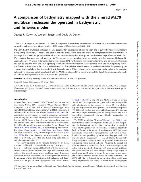
ICES Journal <strong>of</strong> Marine Science Advance Access published March 23, 2010<br />
A <strong>comparison</strong> <strong>of</strong> <strong>bathymetry</strong> <strong>mapped</strong> <strong>with</strong> <strong>the</strong> <strong>Simrad</strong> <strong>ME70</strong><br />
multibeam echosounder operated in bathymetric<br />
and fisheries modes<br />
George R. Cutter Jr, Laurent Berger, and David A. Demer<br />
Page 1 <strong>of</strong> 9<br />
Cutter, G. R. Jr, Berger, L., and Demer, D. A. 2010. A <strong>comparison</strong> <strong>of</strong> <strong>bathymetry</strong> <strong>mapped</strong> <strong>with</strong> <strong>the</strong> <strong>Simrad</strong> <strong>ME70</strong> multibeam echosounder<br />
operated in bathymetric and fisheries modes. – ICES Journal <strong>of</strong> Marine Science, 67: 000–000.<br />
The <strong>Simrad</strong> <strong>ME70</strong> multibeam echosounder was designed for quantitative fisheries research and is currently installed on Ifremer’s<br />
fishery survey vessel (FSV) “Thalassa” and each <strong>of</strong> <strong>the</strong> new, quiet, NOAA FSVs. The <strong>ME70</strong> has configurable beams and transmits in<br />
<strong>the</strong> range 70–120 kHz to provide calibrated, acoustic-backscattering data throughout <strong>the</strong> detection range (fisheries mode, FM).<br />
With optional hardware and s<strong>of</strong>tware, <strong>the</strong> <strong>ME70</strong> can also collect soundings that potentially meet International Hydrographic<br />
Organization’s S–44 Order 1 standards (bathymetric mode, BM). Fur<strong>the</strong>rmore, <strong>with</strong> custom algorithms and s<strong>of</strong>tware, bathymetric<br />
data can be obtained from <strong>the</strong> <strong>ME70</strong> operating in FM, and volume backscatter can be sampled from <strong>the</strong> <strong>ME70</strong> operating in BM.<br />
This flexibility allows data to be concurrently collected on fish and <strong>the</strong>ir seabed habitat. A method is described for processing <strong>the</strong><br />
echo amplitude and phase data from multiple split-beams formed in FM to estimate seabed range, slope, and roughness. The resulting<br />
<strong>bathymetry</strong> is compared <strong>with</strong> that collected <strong>with</strong> <strong>the</strong> <strong>ME70</strong> operating in BM in <strong>the</strong> same area <strong>of</strong> <strong>the</strong> Bay <strong>of</strong> Biscay. A proposal is made<br />
for s<strong>of</strong>tware development to facilitate dual-use data processing.<br />
Keywords: <strong>bathymetry</strong>, mapping, <strong>ME70</strong>, multibeam echosounder, NOAA FSV, split-beam.<br />
Received 7 August 2009; accepted 15 January 2010.<br />
G. R. Cutter Jr and D. A. Demer: NOAA, Southwest Fisheries Science Center, 8604 La Jolla Shores Drive, La Jolla, CA 9203, USA. L. Berger,:<br />
Département NSE, Ifremer, Plouzané, France. Correspondence to G. R. Cutter Jr: tel: þ1 858 546 5619; fax: þ1 858 546 5656; e-mail: george.<br />
cutter@noaa.gov.<br />
Introduction<br />
Ifremer’s fishery survey vessel (FSV) “Thalassa” and each <strong>of</strong> <strong>the</strong><br />
new, quiet, NOAA FSVs (currently “Oscar Dyson”, “Henry<br />
B. Bigelow”, “Pisces”, and “Bell M. Shimada”) are equipped <strong>with</strong><br />
<strong>Simrad</strong> <strong>ME70</strong>, multibeam echosounders. The <strong>ME70</strong> was designed<br />
collaboratively by <strong>Simrad</strong> and Ifremer (Trenkel et al., 2008) for<br />
quantitative acoustic surveys <strong>of</strong> marine organisms, particularly<br />
those residing near <strong>the</strong> seabed. Like a typical multibeam echosounder,<br />
<strong>the</strong> <strong>ME70</strong> forms a fan <strong>of</strong> beams athwartships using an<br />
800-element array. Unlike conventional multibeam echosounders,<br />
<strong>the</strong> <strong>ME70</strong> allows split-aperture processing for any beam (e.g.<br />
Shirazi et al., 1992; Shippey, 1997) in both alongship and athwartship<br />
planes (Demer et al., 1999, 2009; Cutter and Demer, 2010)<br />
and field calibrations using standard-sphere techniques (Ona<br />
et al., 2009). The beam directions can be automatically compensated<br />
to +108 roll, +58 pitch, and heave using data from an<br />
inertial-motion unit (IMU).<br />
The <strong>ME70</strong>, operating in its standard fisheries mode (FM),<br />
provides calibrated volume-backscattering strength (S v ;<br />
dB re m 21 ) and target strength (TS; dBre1m 2 ) data from watercolumn<br />
scatterers <strong>with</strong>in <strong>the</strong> detection range and automated estimates<br />
<strong>of</strong> <strong>the</strong> seabed ranges using amplitude-based detections.<br />
These data provide observations <strong>of</strong> fish and plankton including<br />
<strong>the</strong> estimates <strong>of</strong> <strong>the</strong>ir distributions and abundances, and threedimensional<br />
images <strong>of</strong> <strong>the</strong>ir aggregations and seabed habitat<br />
(Trenkel et al., 2008). The FM uses <strong>ME70</strong> s<strong>of</strong>tware for system<br />
control and data input/output (I/O) and is user-configurable<br />
<strong>with</strong> adjustments to <strong>the</strong> number <strong>of</strong> beams (3–45), whe<strong>the</strong>r<br />
<strong>the</strong>y are single-beam or split-aperture, <strong>the</strong>ir transmit frequency<br />
(70–120 kHz), overlap, and beam width (minimum 28), steering,<br />
and swath angles. Depending on <strong>the</strong> configuration, <strong>the</strong> <strong>ME70</strong><br />
can achieve unmatched two-way sidelobe suppression to<br />
270 dB in FM.<br />
The <strong>ME70</strong> installed on “Thalassa” (Trenkel et al., 2008) is configured<br />
<strong>with</strong> an optional bathymetric module, so can also be operated<br />
in bathymetric mode (BM) to emulate a standard<br />
seabed-mapping multibeam echosounder. The BM has a relatively<br />
fixed configuration including: single-frequency (90 kHz) transmissions;<br />
80 equidistant or equiangle beams, each <strong>with</strong> two pulseduration<br />
options, providing up to 200 soundings per swath; and<br />
one-way sidelobe suppression to 217.5 dB (beams formed only<br />
during reception). Using a <strong>Simrad</strong> EM processor station and SIS<br />
s<strong>of</strong>tware for system control and data I/O, as for <strong>the</strong> <strong>Simrad</strong> EM<br />
series multibeam echosounders, <strong>the</strong> BM estimates ranges to <strong>the</strong><br />
seabed using amplitude detection <strong>with</strong> near-normal incidence<br />
and phase detection for more oblique (low-grazing) angles. If<br />
sound-speed pr<strong>of</strong>ile data are input, <strong>the</strong> processor corrects range<br />
and location estimates for <strong>the</strong> effects <strong>of</strong> sound refraction. The<br />
<strong>ME70</strong> <strong>with</strong> BM is designed to output data which could meet<br />
survey requirements that satisfy <strong>the</strong> International Hydrographic<br />
Downloaded from http://icesjms.oxfordjournals.org at Univ <strong>of</strong> California, San Diego Library on March 25, 2010<br />
# United States Government, National Oceanic and Atmospheric Administration, National Marine Fisheries Service, Southwest Fisheries<br />
Science Center 2010
Page 2 <strong>of</strong> 9<br />
G. R. Cutter et al.<br />
Organization’s (IHO) S–44 Order 1 standard (Kongsberg<br />
Maritime, 2003).<br />
In terms <strong>of</strong> seabed mapping, <strong>the</strong> principal difference between<br />
<strong>the</strong> FM and <strong>the</strong> BM is <strong>the</strong> seabed-detection scheme, although<br />
<strong>the</strong>re are o<strong>the</strong>r differences such as <strong>the</strong> number <strong>of</strong> beams, transmit<br />
power, and side-lobe suppression. Near-normal incidence, <strong>the</strong><br />
sample corresponding to <strong>the</strong> seabed range, can be estimated accurately<br />
using <strong>the</strong> peak or centre-<strong>of</strong>-mass <strong>of</strong> <strong>the</strong> seabed echo, after<br />
filtering or thresholding to avoid spurious detections <strong>of</strong> <strong>the</strong> transmit<br />
pulse or strong water-column scatterers. However, for oblique<br />
angles caused by <strong>the</strong> orientation <strong>of</strong> <strong>the</strong> transducer, <strong>the</strong> beam direction,<br />
and <strong>the</strong> seabed slope, <strong>the</strong> phase differences between wavefronts<br />
received by different elements or portions <strong>of</strong> <strong>the</strong> receiver<br />
array (interferometric phase differences) can be used to estimate<br />
more accurately <strong>the</strong> range to <strong>the</strong> seabed. The moment when <strong>the</strong><br />
phase difference is equal to zero indicates <strong>the</strong> range to <strong>the</strong><br />
seabed at <strong>the</strong> centre <strong>of</strong> <strong>the</strong> beam. However, interferometric<br />
phase can be used to estimate multiple ranges to <strong>the</strong> seabed<br />
<strong>with</strong>in each beam (Jin and Tang, 1996). The BM employs both<br />
strategies, dependent on incidence angle and echo properties,<br />
whereas <strong>the</strong> default method in FM is only peak-echo detection.<br />
Note that <strong>the</strong> seabed-detection algorithms employed in BM can<br />
also be used <strong>with</strong> <strong>the</strong> FM data. Therefore, <strong>with</strong> custom algorithms<br />
and s<strong>of</strong>tware, bathymetric data can be obtained from <strong>the</strong> <strong>ME70</strong><br />
operating in FM and S v . TS can be sampled from <strong>the</strong> <strong>ME70</strong> operating<br />
in BM (see Figure 1 for more details). This flexibility allows<br />
data on fish and <strong>the</strong>ir seabed habitat to be collected concurrently<br />
and efficiently.<br />
Here, we demonstrate that <strong>the</strong> <strong>ME70</strong> operating in FM can<br />
produce high-resolution <strong>bathymetry</strong> data that are equivalent to<br />
those produced by <strong>the</strong> <strong>ME70</strong> operating in BM. Such processing<br />
allows <strong>the</strong> <strong>ME70</strong> to collect data simultaneously and efficiently<br />
from marine organisms, <strong>the</strong>ir seabed habitat, and navigationalquality<br />
bathymetric maps, <strong>with</strong>out <strong>the</strong> configuration limitations<br />
<strong>of</strong> <strong>the</strong> BM and <strong>the</strong> costs associated <strong>with</strong> <strong>the</strong> bathymetric option<br />
Figure 1. Data-processing sequence for <strong>the</strong> <strong>ME70</strong> in BM and FM.<br />
Ancillary data are input from <strong>the</strong> IMU, global-positioning-system<br />
receiver, and conductivity and temperature pr<strong>of</strong>iler (CT). With custom<br />
algorithms and s<strong>of</strong>tware to derive high-resolution <strong>bathymetry</strong> data<br />
from <strong>the</strong> raw files and to convert <strong>the</strong> results to all or GSF format,<br />
high-resolution bathymetric data can be obtained from <strong>the</strong> <strong>ME70</strong><br />
operating in FM. This flexibility allows data to be collected<br />
concurrently and efficiently on fish and <strong>the</strong>ir seabed habitat.<br />
and <strong>the</strong> ship time needed to survey an area twice or more to<br />
collect both FM and BM data.<br />
Methods<br />
Data were collected <strong>with</strong> <strong>the</strong> <strong>ME70</strong> <strong>with</strong> its transducer mounted on<br />
<strong>the</strong> hull <strong>of</strong> RV “Thalassa”, in <strong>the</strong> Bay <strong>of</strong> Biscay, west <strong>of</strong> France, ca.<br />
46831.5 0 N04844.5 0 W, on 19 March 2008. Initially <strong>the</strong>y were collected<br />
in BM, transiting from <strong>the</strong> sou<strong>the</strong>ast to <strong>the</strong> northwest,<br />
and <strong>the</strong>n in <strong>the</strong> same area, in FM, from <strong>the</strong> northwest to <strong>the</strong> sou<strong>the</strong>ast.<br />
The common coverage area was 0.30 km 2 , comprising a track<br />
1.7 km long and ,0.2 km wide. In BM, <strong>the</strong> 80 beams provided a<br />
1208 swath and some 150 soundings per transmission. The FM was<br />
configured, for ano<strong>the</strong>r investigation, to record to a depth <strong>of</strong><br />
232 m, <strong>with</strong> 21 beams from six transmission-pulse groups, each<br />
<strong>with</strong> one or four beams, <strong>with</strong> beam widths from 2.38 to 3.88<br />
(Table 1), resulting in a narrower (608) swath (Figure 2). Note<br />
that <strong>the</strong> FM mode could have been configured <strong>with</strong> a swath<br />
width equivalent to that for <strong>the</strong> BM, and to collect data to a<br />
larger range, but this was not done out <strong>of</strong> consideration for<br />
o<strong>the</strong>r experiments. The pulse duration was 0.268 ms in BM and<br />
1.024 ms in FM. Beam centre-frequencies in FM ranged from<br />
71.9 to 118.1 kHz, and <strong>the</strong> frequency distribution was arranged<br />
<strong>with</strong> <strong>the</strong> highest frequency at <strong>the</strong> 08 beam, <strong>with</strong> frequency decreasing<br />
<strong>with</strong> increasing athwartships angle to achieve an “inverted V”<br />
pattern (Trenkel et al., 2008). In BM, all beams have a centre frequency<br />
<strong>of</strong> 90 kHz.<br />
Custom s<strong>of</strong>tware was developed to emulate <strong>the</strong> BM data processing<br />
and to generate bathymetric data from <strong>the</strong> <strong>ME70</strong> operating<br />
in FM; <strong>the</strong>se data were <strong>the</strong>n compared <strong>with</strong> <strong>the</strong> data from <strong>the</strong><br />
<strong>ME70</strong> operating in BM. A local Cartesian-coordinate system was<br />
defined from an origin x 0 ,y 0 ,z 0 at <strong>the</strong> centre <strong>of</strong> <strong>the</strong> transducer<br />
face and <strong>with</strong> positive values <strong>of</strong> x, y, and z along orthogonal axes<br />
pointing in <strong>the</strong> alongships, starboard, and downward-vertical<br />
directions. Ranges to <strong>the</strong> seabed measured in <strong>the</strong> centre <strong>of</strong> each<br />
beam [r(u, t)], for each beam-steering angle u and transmission<br />
time t, were estimated using amplitude detection near-vertical<br />
incidence angles (,88), and phase detection for larger beam<br />
angles. Amplitude detection was by filtering <strong>the</strong> S v dataseries to<br />
retain samples <strong>with</strong> ranges exceeding a specified minimum<br />
range, sufficient to avoid returns from <strong>the</strong> initial pulse, and<br />
values <strong>of</strong> S v –50 dB to define a contiguous set <strong>of</strong> candidate<br />
samples. The amplitude-detected range was <strong>the</strong> range corresponding<br />
to <strong>the</strong> centre-<strong>of</strong>-mass <strong>of</strong> <strong>the</strong> S v values from candidate samples.<br />
For each beam, trigonometry was used to convert <strong>the</strong> estimated<br />
range to <strong>the</strong> seabed r to an uncorrected depth z u (u, t) by accounting<br />
for u in <strong>the</strong> athwartships (y) direction. Beams were automatically<br />
steered to an angle equal to zero degrees in <strong>the</strong> alongships (x)<br />
direction. The local positions for <strong>the</strong> bottom detections x, y, z u<br />
represented horizontal and vertical distances relative to x 0 ,y 0 ,z 0 .<br />
The z u values were <strong>the</strong>n compensated for transducer depth,<br />
heave, and tidal elevation to estimate local positions <strong>with</strong> corrected<br />
depths (x, y, z corr (u, t)). Then, using geographic position and<br />
course data from <strong>the</strong> global-positioning-system receiver, <strong>the</strong>se<br />
were converted to global Easting (E; m) and Northing (N; m)<br />
coordinates, in zone 30 north <strong>of</strong> a Universal Transverse<br />
Mercator projection referenced to WGS–84, and depths (z).<br />
Although possible, <strong>the</strong>se data were not compensated for <strong>the</strong><br />
effects <strong>of</strong> sound refraction.<br />
The bathymetric data from <strong>the</strong> <strong>ME70</strong> in BM (.all format) were<br />
processed using standard methods and s<strong>of</strong>tware. Specifically,<br />
CARIS Hydrographic Information Processing System (HIPS)<br />
Downloaded from http://icesjms.oxfordjournals.org at Univ <strong>of</strong> California, San Diego Library on March 25, 2010
High-resolution bathymetric mapping <strong>with</strong> <strong>the</strong> <strong>ME70</strong> Page 3 <strong>of</strong> 9<br />
Table 1. Beam-configuration summary for <strong>the</strong> <strong>ME70</strong> FM survey.<br />
Beam<br />
Frequency<br />
(Hz)<br />
Beam<br />
direction (8)<br />
Beam-width<br />
alongships (8)<br />
Beam-width<br />
athwartships (8)<br />
Angle-sensitivity<br />
alongships<br />
1 71 943 230.5 3.79 4.40 63.3<br />
2 76 449 226.2 3.57 3.98 67.3<br />
3 80 956 222.5 3.37 3.65 71.3<br />
4 85 462 219.0 3.19 3.37 75.2<br />
5 89 969 215.7 3.03 3.15 79.2<br />
6 94 476 212.7 2.89 2.96 83.1<br />
7 98 982 29.8 2.75 2.80 87.1<br />
8 103 489 27.1 2.63 2.66 91.1<br />
9 107 995 24.5 2.53 2.53 95.0<br />
10 112 502 22.0 2.42 2.43 99.0<br />
11 118 057 0.4 2.31 2.31 103.9<br />
12 114 755 2.7 2.38 2.38 101.0<br />
13 110 249 5.1 2.47 2.48 97.0<br />
14 105 742 7.7 2.58 2.60 93.1<br />
15 101 235 10.4 2.69 2.74 89.1<br />
16 96 729 13.2 2.82 2.90 85.1<br />
17 92 222 16.2 2.96 3.08 81.2<br />
18 87 716 19.3 3.11 3.30 77.2<br />
19 83 209 22.8 3.28 3.55 73.2<br />
20 78 702 26.5 3.46 3.87 69.3<br />
21 74 196 30.5 3.68 4.27 65.3<br />
Downloaded from http://icesjms.oxfordjournals.org at Univ <strong>of</strong> California, San Diego Library on March 25, 2010<br />
Figure 2. Locations <strong>of</strong> soundings from BM and FM, <strong>with</strong> <strong>the</strong> FM configured for a 608 swath width, and <strong>the</strong> BM configured for 1208. Thewhole<br />
numbers on <strong>the</strong> axes <strong>of</strong> this and subsequent Figures are <strong>the</strong> coordinate values, in units <strong>of</strong> metres, from a Universal Transverse Mercator projection.
Page 4 <strong>of</strong> 9<br />
G. R. Cutter et al.<br />
s<strong>of</strong>tware was used to remove outliers, examine <strong>the</strong> motion data,<br />
compensate for tidal elevation and refraction, merge data, create<br />
surfaces, and export <strong>the</strong> results for display and <strong>comparison</strong> in<br />
ESRI ArcMap GIS.<br />
Bathymetric maps were generated for <strong>the</strong> same area using data<br />
from <strong>the</strong> <strong>ME70</strong> operating in both BM and FM. The sampling coverage<br />
and bathymetric maps from BM and FM modes are compared<br />
in plan view (Figures 3 and 4). The <strong>bathymetry</strong> from each<br />
mode is also compared in perspective, viewed from <strong>the</strong> northwest<br />
at an elevation <strong>of</strong> 358, after processing <strong>the</strong> FM data <strong>with</strong> amplitude<br />
detections (Figure 5a), <strong>the</strong>n amplitude and phase detections <strong>of</strong> <strong>the</strong><br />
seabed (Figure 5b). The quality <strong>of</strong> <strong>the</strong> FM solutions is evaluated by<br />
subtracting <strong>the</strong> BM and FM surfaces (Figure 6). Additionally,<br />
seabed slopes were estimated by differences in depths between<br />
neighbouring grid cells, for both <strong>the</strong> BM and FM data<br />
(Figure 7). Local roughness was estimated for both <strong>the</strong> BM and<br />
FM surfaces from <strong>the</strong> standard deviation (s.d.) <strong>of</strong> depth values<br />
<strong>with</strong>in 15 15 m cells (Figure 8).<br />
Results<br />
The common survey area has a smooth, locally flat seabed <strong>with</strong><br />
depths ranging from 204 to 232 m. This is fortuitous for<br />
<strong>comparison</strong>s and optimizations <strong>of</strong> <strong>the</strong> FM seabed-detection<br />
methods. The effective swath <strong>of</strong> <strong>the</strong> FM data is reduced as <strong>the</strong><br />
depth approaches <strong>the</strong> maximum detection range <strong>of</strong> 232 m; this<br />
effect could be mitigated <strong>with</strong> ano<strong>the</strong>r FM configuration having<br />
a greater swath width and larger maximum detection range. The<br />
maximum detection range <strong>of</strong> FM mode is, however, reduced compared<br />
<strong>with</strong> BM because <strong>of</strong> simultaneous transmissions <strong>of</strong> up to<br />
four beams, and beamforming at both transmission and reception.<br />
The mean difference in <strong>the</strong> BM vs. FM depths is virtually zero.<br />
The principal differences are due only to <strong>the</strong> amplitude detection<br />
in <strong>the</strong> FM data at large incidence angles (Figure 5a). Even <strong>the</strong>se<br />
differences are removed when using <strong>the</strong> amplitude and phase<br />
detection method <strong>with</strong> <strong>the</strong> FM data (Figure 5b). The remaining<br />
differences are believed to be residuals <strong>of</strong> uncompensated, or inaccurately<br />
compensated, motion artefacts, predominantly caused by<br />
heave, as well as navigational positioning errors. Heave artefacts in<br />
both FM and BM result from <strong>the</strong> internal filter <strong>of</strong> <strong>the</strong> motion<br />
sensor, and in <strong>the</strong> former, heave compensation only occurs at<br />
<strong>the</strong> time <strong>of</strong> transmission. The median depth <strong>of</strong> <strong>the</strong> area was<br />
214 m, and <strong>the</strong> mean difference in depth between <strong>the</strong> BM and<br />
FM results was 0.54 m (s.d. ¼ 0.37 m). The mean difference<br />
between FM and BM depths included a bias (0.54 m) that is<br />
Downloaded from http://icesjms.oxfordjournals.org at Univ <strong>of</strong> California, San Diego Library on March 25, 2010<br />
Figure 3. Plan view <strong>of</strong> <strong>the</strong> shaded relief bathymetric surface from <strong>the</strong> <strong>ME70</strong> in BM, coloured by depth, and <strong>with</strong> <strong>the</strong> FM coverage outlined.<br />
The surface is a regular grid <strong>with</strong> 5 5 m grid cells, <strong>with</strong> values representing <strong>the</strong> median depth from 30-m neighbourhoods.
High-resolution bathymetric mapping <strong>with</strong> <strong>the</strong> <strong>ME70</strong> Page 5 <strong>of</strong> 9<br />
Figure 4. Plan view <strong>of</strong> <strong>the</strong> shaded relief bathymetric surface from <strong>the</strong> <strong>ME70</strong> in FM, coloured by depth. The surface is a regular grid <strong>with</strong><br />
5 5 m grid cells, <strong>with</strong> values representing <strong>the</strong> median depth value from 30-m neighbourhoods.<br />
believed to be related to position-data inaccuracy or imprecision,<br />
or to <strong>the</strong> estimation <strong>of</strong> tides. Without compensating for <strong>the</strong> bias,<br />
<strong>the</strong> difference between BM and FM depths was ,1.6% for 100%<br />
<strong>of</strong> <strong>the</strong> common coverage area, <strong>with</strong> corresponding bathymetric<br />
grid cells, ,0.65% for 99% <strong>of</strong> <strong>the</strong> area, ,0.52% for 95% <strong>of</strong> <strong>the</strong><br />
area, ,0.46% for 90% <strong>of</strong> <strong>the</strong> area, and ,0.27% for 50% <strong>of</strong> <strong>the</strong><br />
area (Figure 6). The difference between BM and FM mean<br />
depths was ,0.5%, which also corresponds to <strong>the</strong> accuracy <strong>of</strong><br />
<strong>the</strong> BM mode, for 93% <strong>of</strong> <strong>the</strong> area. After accounting for <strong>the</strong><br />
0.54-m bias by adding it to <strong>the</strong> FM depth values, <strong>the</strong> difference<br />
between mean depths was 20.0047 m, and a test for equality <strong>of</strong><br />
means for BM and FM depths showed no difference between<br />
sample means (pooled-variance, two-sample t-test, t ¼ 20.0414,<br />
d.f. ¼ 10 688, p ¼ 0.967, 95% CI ¼ 20.228 to 0.219 m). In<br />
o<strong>the</strong>r words, removing <strong>the</strong> bias resulted in a mean difference <strong>of</strong><br />
20.0047 m, and ,0.11% <strong>of</strong> <strong>the</strong> mean depth. A pairwise <strong>comparison</strong><br />
also showed no difference in depths (t ¼ 20.9287, d.f. ¼<br />
5344, p ¼ 0.353, 95% CI ¼ 20.0147 to 0.0053 m). Larger differences,<br />
<strong>of</strong> <strong>the</strong> order <strong>of</strong> 1.5 m, not accounting for <strong>the</strong> unresolved<br />
bias, which are apparent in <strong>the</strong> sou<strong>the</strong>ast portion <strong>of</strong> <strong>the</strong> area, are<br />
probably a combination <strong>of</strong> refraction, tidal effects, and positioning<br />
error.<br />
The largest slopes (5–148) are evident in <strong>the</strong> BM data<br />
(Figure 7a) as <strong>the</strong> seabed smoothly changes from shelf to<br />
slope. In <strong>the</strong> common survey area, <strong>the</strong> slopes are generally<br />
,28 (Figure 7b). Values <strong>of</strong> 2–38 are associated <strong>with</strong> detection<br />
artefacts, residual motion, and <strong>the</strong> shape <strong>of</strong> <strong>the</strong> seabed sloping<br />
downwards towards <strong>the</strong> sou<strong>the</strong>ast. Both <strong>the</strong> BM and FM<br />
results indicate that <strong>the</strong> large-scale slope is controlling <strong>the</strong><br />
seabed roughness in this area (Figure 8). The local roughness<br />
is ,10 cm for most <strong>of</strong> <strong>the</strong> common area, increasing to 1 m<br />
for <strong>the</strong> large depressions. Minor variation in <strong>the</strong> slope, and<br />
hence <strong>the</strong> roughness, is a result <strong>of</strong> residual motion artefacts in<br />
<strong>the</strong> BM results. The minor variation in <strong>the</strong> slope in FM<br />
results stems from <strong>the</strong> fixed angle used to switch from amplitude<br />
to phase detections.<br />
Discussion<br />
By employing standard amplitude- and phase-based seabeddetection<br />
methods, data collected in <strong>the</strong> BM and FM modes<br />
produce practically equivalent results for <strong>the</strong> relatively flat<br />
seabed <strong>of</strong> <strong>the</strong> study area. Although <strong>the</strong> <strong>comparison</strong> was only for<br />
<strong>bathymetry</strong> estimated for a relatively flat seabed, an analysis <strong>of</strong><br />
FM and BM data from a rough seabed (not shown) demonstrated<br />
Downloaded from http://icesjms.oxfordjournals.org at Univ <strong>of</strong> California, San Diego Library on March 25, 2010
Page 6 <strong>of</strong> 9<br />
G. R. Cutter et al.<br />
Figure 5. Perspective <strong>of</strong> <strong>the</strong> shaded relief bathymetric surfaces from <strong>the</strong> <strong>ME70</strong> FM surface resulting from (a) amplitude detection only and <strong>the</strong><br />
BM surface, and (b) amplitude detection used <strong>with</strong>in 88 <strong>of</strong> normal incidence and phase detection used for incidence angles .88, and <strong>the</strong> BM<br />
surface.<br />
Downloaded from http://icesjms.oxfordjournals.org at Univ <strong>of</strong> California, San Diego Library on March 25, 2010<br />
Figure 6. Difference in depths (dz; m) by grid cell between <strong>the</strong> BM and FM bathymetric surfaces, coloured by dz in intervals <strong>of</strong> 0.5 m. The<br />
mean difference was ,50 cm for approximately half <strong>the</strong> area, and ,1 m for 95% <strong>of</strong> <strong>the</strong> area, for an area <strong>with</strong> a mean depth <strong>of</strong> 220 m.<br />
that <strong>the</strong> results are practically equivalent for ei<strong>the</strong>r rough or flat<br />
seabed when positioning data are accurate and precise for both<br />
datasets.<br />
Possible limitations <strong>of</strong> <strong>the</strong> FM are <strong>the</strong> reduced pulse-repetition<br />
rate and number <strong>of</strong> beams, and <strong>the</strong> increased pulse duration.<br />
Generally, increased pulse duration diminishes <strong>the</strong> accuracy and
High-resolution bathymetric mapping <strong>with</strong> <strong>the</strong> <strong>ME70</strong> Page 7 <strong>of</strong> 9<br />
Figure 7. Seabed-slope angles estimated from <strong>the</strong> difference in elevations among neighbouring grid cells for (a) <strong>the</strong> BM, and (b) <strong>the</strong> FM<br />
surfaces. Colour classes indicate differences in slope angle at 18 intervals, from 08 to 58, and one class for .58. The mean slope for most <strong>of</strong> <strong>the</strong><br />
common coverage area was ,28, and <strong>the</strong> slope values estimated from <strong>the</strong> BM and FM surfaces are virtually <strong>the</strong> same. Discrepancies stem from<br />
residual motion artefacts in <strong>the</strong> BM surface and where <strong>the</strong> change from amplitude to phase detection is in <strong>the</strong> FM surface.<br />
Downloaded from http://icesjms.oxfordjournals.org at Univ <strong>of</strong> California, San Diego Library on March 25, 2010<br />
Figure 8. Seabed roughness as <strong>the</strong> standard deviation <strong>of</strong> data <strong>with</strong>in 15-m neighbourhoods, estimated for each 5-m grid cell. The roughness<br />
was ,20 cm for most <strong>of</strong> <strong>the</strong> common coverage area for (a) BM and (b) FM bathymetric surfaces.<br />
spatial resolution <strong>of</strong> bottom-detection solutions from standard<br />
methods. However, a method introduced by Demer et al. (2009)<br />
and enhanced by Cutter and Demer (2010) holds <strong>the</strong> promise <strong>of</strong><br />
overcoming <strong>the</strong>se perceived limitations, at least for <strong>bathymetry</strong>,<br />
and provides multiple soundings per split-aperture beam.<br />
Never<strong>the</strong>less, s<strong>of</strong>tware needs to be developed that uses conventional<br />
or new methods to process <strong>the</strong> <strong>ME70</strong> FM data. For example,<br />
high-resolution bathymetric data could be generated from <strong>ME70</strong>
Page 8 <strong>of</strong> 9<br />
G. R. Cutter et al.<br />
FM using a program that processes <strong>the</strong> data as shown here and also<br />
reformats <strong>the</strong> output into a standard format (e.g. .all format) for<br />
input into standard bathymetric data-processing s<strong>of</strong>tware<br />
packages (e.g. Caris HIPS, Hypack, or Triton). Many such<br />
packages also include CUBE (Calder and Mayer, 2003), an algorithm<br />
for estimating seabed depths and <strong>the</strong> uncertainty in <strong>the</strong>se<br />
estimates.<br />
Such a program could evolve to incorporate improved<br />
methods for seabed detection and classification data. For<br />
example, <strong>the</strong> method <strong>of</strong> Bourguignon et al. (2009) uses<br />
models and information from multiple beams to determine<br />
<strong>the</strong> statistical probability <strong>of</strong> a detection. Alternatively,<br />
Statistical–Spectral Identification (SSID; Demer et al., 2009)<br />
and Multifrequency Bi-planar Interferometric Imaging (MBI;<br />
Cutter and Demer, 2010) could be exploited; <strong>the</strong>y use <strong>with</strong>inbeam<br />
amplitude and phase information to provide more<br />
robust and high-resolution estimations <strong>of</strong> seabed range, slope,<br />
hardness, and roughness from echo amplitudes and phase differences.<br />
However, fur<strong>the</strong>r analyses need to be conducted to configure<br />
FM for optimal application <strong>of</strong> <strong>the</strong> SSID and MBI<br />
methods, and <strong>comparison</strong> <strong>with</strong> <strong>the</strong> FM configured to emulate<br />
a bathymetric multibeam <strong>with</strong> many narrowbeams.<br />
There are many advantages to collecting data <strong>with</strong> <strong>the</strong> <strong>ME70</strong> in<br />
FM compared <strong>with</strong> BM. Beyond <strong>the</strong> additional costs <strong>of</strong> <strong>the</strong> bathymetric<br />
module and <strong>the</strong> need to survey areas in BM and <strong>the</strong>n FM,<br />
<strong>the</strong> FM is much more configurable and <strong>of</strong>fers two-way beamforming,<br />
which more than doubles <strong>the</strong> side-lobe suppression.<br />
The BM uses a single-frequency transmission, and beams are<br />
formed only during reception (one-way side-lobe suppression,<br />
e.g. 225 dB in <strong>the</strong> athwartships dimension through classical<br />
array weighting). In stark contrast, <strong>the</strong> acoustic cross-talk<br />
between beams is reduced approximately to 2–3 orders <strong>of</strong> magnitude<br />
in FM (reduced by 70 dB, depending on array weighting).<br />
This notable reduction is accomplished by two-way<br />
narrowbeams, side-lobe suppression, and frequency filtering.<br />
Consequently, <strong>the</strong> transmission and <strong>the</strong> reception <strong>of</strong> each beam<br />
have a unique bandwidth, and <strong>the</strong> sidelobe <strong>of</strong> <strong>the</strong> vertical beam<br />
is filtered in <strong>the</strong> main lobe <strong>of</strong> <strong>the</strong> steered beam. The FM also provides<br />
multifrequency operation for spectral classification <strong>of</strong> <strong>the</strong><br />
water column and seabed scatterers (Demer et al., 2009).<br />
Increased pulse duration, typically 2 ms for FM vs. 0.2 ms for<br />
BM for a swath <strong>of</strong> 1208, will, however, lead to averaged measurements<br />
for seabed backscatter in FM and reduced resolution for<br />
associated metrics for hardness measurements, which could be<br />
a limitation in this mode. Not<strong>with</strong>standing, new methods for<br />
higher resolution, sub-beam estimates <strong>of</strong> volume and surface<br />
backscatter (e.g. Cutter and Demer, 2010) could help rectify or<br />
even reverse this disparity.<br />
Active beam steering is used by <strong>the</strong> <strong>ME70</strong> to compensate for<br />
vessel motion. As only up to 45 beams can be formed in FM,<br />
such beams are commonly formed that are wider than BM<br />
beams to maximize coverage. During active steering, beams are<br />
deformed relative to <strong>the</strong> calibrated-beam shapes, and this can<br />
lead to errors in <strong>the</strong> volume-backscattering coefficients calculated<br />
using <strong>the</strong> calibration-beam model and gain adjustments. The effect<br />
and error are enhanced for greater beam-direction angles, away<br />
from <strong>the</strong> broadside <strong>of</strong> <strong>the</strong> planar-array transducer. To avoid this<br />
effect and potential error when using FM and a configuration<br />
<strong>with</strong> wide beams, motion compensation could be turned <strong>of</strong>f so<br />
that <strong>the</strong> calibrations will remain accurate. It could <strong>the</strong>n be<br />
applied in post-processing.<br />
Conclusions<br />
Accurate and precise <strong>bathymetry</strong> can be obtained from <strong>the</strong> <strong>ME70</strong><br />
operating in FM and BM. The differences between <strong>the</strong> BM and FM<br />
surfaces were ,0.65% <strong>of</strong> depth at .200 m for 99% <strong>of</strong> <strong>the</strong><br />
common survey area, after accounting for a 0.54-m bias. The<br />
differences were ,0.25 and ,0.5% <strong>of</strong> depth for 45 and 93% <strong>of</strong><br />
<strong>the</strong> common area, respectively. Taking account <strong>of</strong> refraction, and<br />
<strong>with</strong> more accurate positioning data, <strong>the</strong> bias and <strong>the</strong>se differences<br />
are likely to be less. Using different beam configurations in FM and<br />
alternative bottom-detection methods (e.g. Demer et al., 2009;<br />
Cutter and Demer, 2010), <strong>the</strong> differences could be reduced<br />
fur<strong>the</strong>r, <strong>the</strong> spatial resolution <strong>of</strong> <strong>the</strong> FM soundings could be<br />
improved beyond that provided by <strong>the</strong> BM or <strong>the</strong> FM configured<br />
<strong>with</strong> many narrowbeams, and <strong>the</strong> seabed could be characterized<br />
and classified.<br />
The BM option is designed specifically for bathymetric<br />
mapping and includes processing hardware and s<strong>of</strong>tware for computing<br />
<strong>bathymetry</strong> and seabed images in real time, and standard<br />
bathymetric-mapping products <strong>with</strong> post-processing. Raw data<br />
collected <strong>with</strong> <strong>the</strong> BM could also be used for some water-column<br />
studies not affected by high side-lobe levels, but <strong>the</strong>re is currently<br />
no commercial post-processing s<strong>of</strong>tware for this purpose.<br />
For <strong>the</strong> <strong>ME70</strong> operating in FM, <strong>the</strong>re is also a lack <strong>of</strong> commercial<br />
post-processing s<strong>of</strong>tware for both bathymetric-mapping and<br />
water-column studies. This situation can be easily mitigated for<br />
seabed studies <strong>with</strong> <strong>the</strong> development <strong>of</strong> s<strong>of</strong>tware that implements<br />
<strong>the</strong> classical methods demonstrated here, or new methods (e.g.<br />
Bourguignon et al., 2009; Demer et al., 2009; Cutter and Demer,<br />
2010) and reformats <strong>the</strong> output into a standard format (e.g.<br />
Generic Sensor Format, or <strong>Simrad</strong> .all) for input into standard<br />
bathymetric data-processing s<strong>of</strong>tware. In addition to bathymetric<br />
data-processing tools for <strong>ME70</strong> FM data, it is important that<br />
methods be developed to process <strong>the</strong> data for water-column<br />
studies. Ultimately, a s<strong>of</strong>tware package would allow processing<br />
<strong>of</strong> <strong>the</strong> <strong>ME70</strong> FM data for integrated analyses <strong>of</strong> marine animals<br />
and <strong>the</strong>ir seabed habitats.<br />
Acknowledgements<br />
We thank L. N. Andersen (<strong>Simrad</strong>) for providing code to read .raw<br />
datagrams; S. Bourguignon (Ifremer) for facilitating <strong>the</strong> exchange<br />
<strong>of</strong> data between Ifremer and SWFSC; and three anonymous referees<br />
for <strong>the</strong>ir reviews <strong>of</strong> <strong>the</strong> manuscript.<br />
References<br />
Bourguignon, S., Berger, L., Scalabrin, C., Fablet, R., and Mazauric, V.<br />
2009. Methodological developments for improved bottom detection<br />
<strong>with</strong> <strong>the</strong> <strong>ME70</strong> multibeam echosounder. ICES Journal <strong>of</strong><br />
Marine Science, 66: 1015–1022.<br />
Calder, B. R., and Mayer, L. A. 2003. Automatic processing <strong>of</strong> highrate,<br />
high-density multibeam echosounder data. In Geochemistry<br />
Geophysics Geosystems, 4. 1048 pp. doi:10.1029/2002GC000486.6.<br />
Cutter, G. R., and Demer, D. A. 2010. Multifrequency-acoustic,<br />
bi-planar, interferometric imaging. IEEE Geoscience and Remote<br />
Sensing Letters, 7: 171–175.<br />
Demer, D. A., Cutter, G. R., Renfree, J. S., and Butler, J. L. 2009. A<br />
statistical–spectral method for echo classification. ICES Journal<br />
<strong>of</strong> Marine Science, 66: 1081–1090.<br />
Demer, D. A., Soule, M. A., and Hewitt, R. P. 1999. A multi-frequency<br />
method for improved accuracy and precision <strong>of</strong> in situ target<br />
strength measurements. Journal <strong>of</strong> <strong>the</strong> Acoustical Society <strong>of</strong><br />
America, 105: 2359–2376.<br />
Downloaded from http://icesjms.oxfordjournals.org at Univ <strong>of</strong> California, San Diego Library on March 25, 2010
High-resolution bathymetric mapping <strong>with</strong> <strong>the</strong> <strong>ME70</strong> Page 9 <strong>of</strong> 9<br />
Jin, G., and Tang, D. 1996. Uncertainties <strong>of</strong> differential phase estimation<br />
associated <strong>with</strong> interferomentric sonars. IEEE Journal <strong>of</strong><br />
Oceanic Engineering, 21: 53–63.<br />
Kongsberg Maritime. 2003. Budgetary Quotation: HOR-03320, Product:<br />
Bathymetric Option, Project: Ifremer, Fishery MBES, for <strong>Simrad</strong> AS.<br />
Ona, E., Mazauric, V., and Andersen, L. N. 2009. Calibration methods<br />
for two scientific multibeam systems. ICES Journal <strong>of</strong> Marine<br />
Science, 66: 1326–1334.<br />
Shippey, G. 1997. Simple algorithms for sonar imaging and <strong>bathymetry</strong><br />
<strong>with</strong> a linear swept-frequency (chirp) source. International<br />
Journal <strong>of</strong> Imaging Systems and Technology, 8: 359–376.<br />
Shirazi, M. A., de Moustier, C., Cervenka, P., and Zisk, S. H. 1992.<br />
Differential phase estimation <strong>with</strong> <strong>the</strong> SeaMARC II bathymetric<br />
sidescan sonar system. IEEE Journal <strong>of</strong> Oceanic Engineering, 17:<br />
239–251.<br />
Trenkel, V. M., Mazauric, V., and Berger, L. 2008. The new fisheries<br />
multibeam echosounder <strong>ME70</strong>: description and expected contribution<br />
to fisheries research. ICES Journal <strong>of</strong> Marine Science, 65:<br />
645–655.<br />
doi:10.1093/icesjms/fsq012<br />
Downloaded from http://icesjms.oxfordjournals.org at Univ <strong>of</strong> California, San Diego Library on March 25, 2010