A comparison of bathymetry mapped with the Simrad ME70 ...
A comparison of bathymetry mapped with the Simrad ME70 ...
A comparison of bathymetry mapped with the Simrad ME70 ...

You also want an ePaper? Increase the reach of your titles
YUMPU automatically turns print PDFs into web optimized ePapers that Google loves.
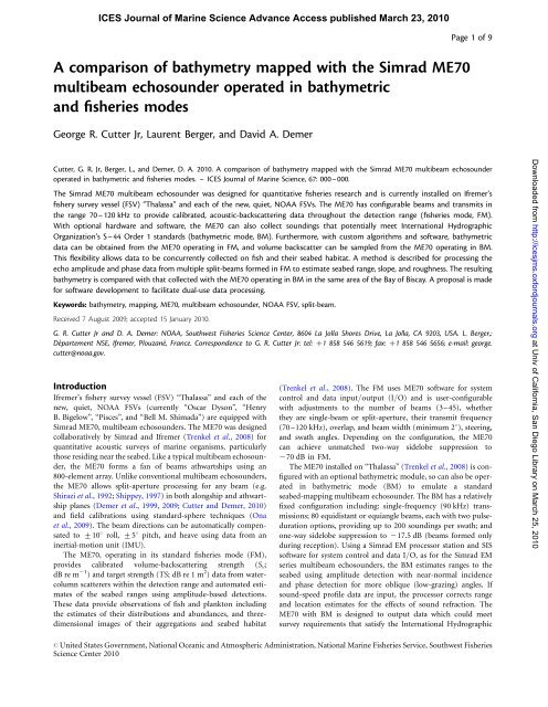
ICES Journal <strong>of</strong> Marine Science Advance Access published March 23, 2010<br />
A <strong>comparison</strong> <strong>of</strong> <strong>bathymetry</strong> <strong>mapped</strong> <strong>with</strong> <strong>the</strong> <strong>Simrad</strong> <strong>ME70</strong><br />
multibeam echosounder operated in bathymetric<br />
and fisheries modes<br />
George R. Cutter Jr, Laurent Berger, and David A. Demer<br />
Page 1 <strong>of</strong> 9<br />
Cutter, G. R. Jr, Berger, L., and Demer, D. A. 2010. A <strong>comparison</strong> <strong>of</strong> <strong>bathymetry</strong> <strong>mapped</strong> <strong>with</strong> <strong>the</strong> <strong>Simrad</strong> <strong>ME70</strong> multibeam echosounder<br />
operated in bathymetric and fisheries modes. – ICES Journal <strong>of</strong> Marine Science, 67: 000–000.<br />
The <strong>Simrad</strong> <strong>ME70</strong> multibeam echosounder was designed for quantitative fisheries research and is currently installed on Ifremer’s<br />
fishery survey vessel (FSV) “Thalassa” and each <strong>of</strong> <strong>the</strong> new, quiet, NOAA FSVs. The <strong>ME70</strong> has configurable beams and transmits in<br />
<strong>the</strong> range 70–120 kHz to provide calibrated, acoustic-backscattering data throughout <strong>the</strong> detection range (fisheries mode, FM).<br />
With optional hardware and s<strong>of</strong>tware, <strong>the</strong> <strong>ME70</strong> can also collect soundings that potentially meet International Hydrographic<br />
Organization’s S–44 Order 1 standards (bathymetric mode, BM). Fur<strong>the</strong>rmore, <strong>with</strong> custom algorithms and s<strong>of</strong>tware, bathymetric<br />
data can be obtained from <strong>the</strong> <strong>ME70</strong> operating in FM, and volume backscatter can be sampled from <strong>the</strong> <strong>ME70</strong> operating in BM.<br />
This flexibility allows data to be concurrently collected on fish and <strong>the</strong>ir seabed habitat. A method is described for processing <strong>the</strong><br />
echo amplitude and phase data from multiple split-beams formed in FM to estimate seabed range, slope, and roughness. The resulting<br />
<strong>bathymetry</strong> is compared <strong>with</strong> that collected <strong>with</strong> <strong>the</strong> <strong>ME70</strong> operating in BM in <strong>the</strong> same area <strong>of</strong> <strong>the</strong> Bay <strong>of</strong> Biscay. A proposal is made<br />
for s<strong>of</strong>tware development to facilitate dual-use data processing.<br />
Keywords: <strong>bathymetry</strong>, mapping, <strong>ME70</strong>, multibeam echosounder, NOAA FSV, split-beam.<br />
Received 7 August 2009; accepted 15 January 2010.<br />
G. R. Cutter Jr and D. A. Demer: NOAA, Southwest Fisheries Science Center, 8604 La Jolla Shores Drive, La Jolla, CA 9203, USA. L. Berger,:<br />
Département NSE, Ifremer, Plouzané, France. Correspondence to G. R. Cutter Jr: tel: þ1 858 546 5619; fax: þ1 858 546 5656; e-mail: george.<br />
cutter@noaa.gov.<br />
Introduction<br />
Ifremer’s fishery survey vessel (FSV) “Thalassa” and each <strong>of</strong> <strong>the</strong><br />
new, quiet, NOAA FSVs (currently “Oscar Dyson”, “Henry<br />
B. Bigelow”, “Pisces”, and “Bell M. Shimada”) are equipped <strong>with</strong><br />
<strong>Simrad</strong> <strong>ME70</strong>, multibeam echosounders. The <strong>ME70</strong> was designed<br />
collaboratively by <strong>Simrad</strong> and Ifremer (Trenkel et al., 2008) for<br />
quantitative acoustic surveys <strong>of</strong> marine organisms, particularly<br />
those residing near <strong>the</strong> seabed. Like a typical multibeam echosounder,<br />
<strong>the</strong> <strong>ME70</strong> forms a fan <strong>of</strong> beams athwartships using an<br />
800-element array. Unlike conventional multibeam echosounders,<br />
<strong>the</strong> <strong>ME70</strong> allows split-aperture processing for any beam (e.g.<br />
Shirazi et al., 1992; Shippey, 1997) in both alongship and athwartship<br />
planes (Demer et al., 1999, 2009; Cutter and Demer, 2010)<br />
and field calibrations using standard-sphere techniques (Ona<br />
et al., 2009). The beam directions can be automatically compensated<br />
to +108 roll, +58 pitch, and heave using data from an<br />
inertial-motion unit (IMU).<br />
The <strong>ME70</strong>, operating in its standard fisheries mode (FM),<br />
provides calibrated volume-backscattering strength (S v ;<br />
dB re m 21 ) and target strength (TS; dBre1m 2 ) data from watercolumn<br />
scatterers <strong>with</strong>in <strong>the</strong> detection range and automated estimates<br />
<strong>of</strong> <strong>the</strong> seabed ranges using amplitude-based detections.<br />
These data provide observations <strong>of</strong> fish and plankton including<br />
<strong>the</strong> estimates <strong>of</strong> <strong>the</strong>ir distributions and abundances, and threedimensional<br />
images <strong>of</strong> <strong>the</strong>ir aggregations and seabed habitat<br />
(Trenkel et al., 2008). The FM uses <strong>ME70</strong> s<strong>of</strong>tware for system<br />
control and data input/output (I/O) and is user-configurable<br />
<strong>with</strong> adjustments to <strong>the</strong> number <strong>of</strong> beams (3–45), whe<strong>the</strong>r<br />
<strong>the</strong>y are single-beam or split-aperture, <strong>the</strong>ir transmit frequency<br />
(70–120 kHz), overlap, and beam width (minimum 28), steering,<br />
and swath angles. Depending on <strong>the</strong> configuration, <strong>the</strong> <strong>ME70</strong><br />
can achieve unmatched two-way sidelobe suppression to<br />
270 dB in FM.<br />
The <strong>ME70</strong> installed on “Thalassa” (Trenkel et al., 2008) is configured<br />
<strong>with</strong> an optional bathymetric module, so can also be operated<br />
in bathymetric mode (BM) to emulate a standard<br />
seabed-mapping multibeam echosounder. The BM has a relatively<br />
fixed configuration including: single-frequency (90 kHz) transmissions;<br />
80 equidistant or equiangle beams, each <strong>with</strong> two pulseduration<br />
options, providing up to 200 soundings per swath; and<br />
one-way sidelobe suppression to 217.5 dB (beams formed only<br />
during reception). Using a <strong>Simrad</strong> EM processor station and SIS<br />
s<strong>of</strong>tware for system control and data I/O, as for <strong>the</strong> <strong>Simrad</strong> EM<br />
series multibeam echosounders, <strong>the</strong> BM estimates ranges to <strong>the</strong><br />
seabed using amplitude detection <strong>with</strong> near-normal incidence<br />
and phase detection for more oblique (low-grazing) angles. If<br />
sound-speed pr<strong>of</strong>ile data are input, <strong>the</strong> processor corrects range<br />
and location estimates for <strong>the</strong> effects <strong>of</strong> sound refraction. The<br />
<strong>ME70</strong> <strong>with</strong> BM is designed to output data which could meet<br />
survey requirements that satisfy <strong>the</strong> International Hydrographic<br />
Downloaded from http://icesjms.oxfordjournals.org at Univ <strong>of</strong> California, San Diego Library on March 25, 2010<br />
# United States Government, National Oceanic and Atmospheric Administration, National Marine Fisheries Service, Southwest Fisheries<br />
Science Center 2010
Page 2 <strong>of</strong> 9<br />
G. R. Cutter et al.<br />
Organization’s (IHO) S–44 Order 1 standard (Kongsberg<br />
Maritime, 2003).<br />
In terms <strong>of</strong> seabed mapping, <strong>the</strong> principal difference between<br />
<strong>the</strong> FM and <strong>the</strong> BM is <strong>the</strong> seabed-detection scheme, although<br />
<strong>the</strong>re are o<strong>the</strong>r differences such as <strong>the</strong> number <strong>of</strong> beams, transmit<br />
power, and side-lobe suppression. Near-normal incidence, <strong>the</strong><br />
sample corresponding to <strong>the</strong> seabed range, can be estimated accurately<br />
using <strong>the</strong> peak or centre-<strong>of</strong>-mass <strong>of</strong> <strong>the</strong> seabed echo, after<br />
filtering or thresholding to avoid spurious detections <strong>of</strong> <strong>the</strong> transmit<br />
pulse or strong water-column scatterers. However, for oblique<br />
angles caused by <strong>the</strong> orientation <strong>of</strong> <strong>the</strong> transducer, <strong>the</strong> beam direction,<br />
and <strong>the</strong> seabed slope, <strong>the</strong> phase differences between wavefronts<br />
received by different elements or portions <strong>of</strong> <strong>the</strong> receiver<br />
array (interferometric phase differences) can be used to estimate<br />
more accurately <strong>the</strong> range to <strong>the</strong> seabed. The moment when <strong>the</strong><br />
phase difference is equal to zero indicates <strong>the</strong> range to <strong>the</strong><br />
seabed at <strong>the</strong> centre <strong>of</strong> <strong>the</strong> beam. However, interferometric<br />
phase can be used to estimate multiple ranges to <strong>the</strong> seabed<br />
<strong>with</strong>in each beam (Jin and Tang, 1996). The BM employs both<br />
strategies, dependent on incidence angle and echo properties,<br />
whereas <strong>the</strong> default method in FM is only peak-echo detection.<br />
Note that <strong>the</strong> seabed-detection algorithms employed in BM can<br />
also be used <strong>with</strong> <strong>the</strong> FM data. Therefore, <strong>with</strong> custom algorithms<br />
and s<strong>of</strong>tware, bathymetric data can be obtained from <strong>the</strong> <strong>ME70</strong><br />
operating in FM and S v . TS can be sampled from <strong>the</strong> <strong>ME70</strong> operating<br />
in BM (see Figure 1 for more details). This flexibility allows<br />
data on fish and <strong>the</strong>ir seabed habitat to be collected concurrently<br />
and efficiently.<br />
Here, we demonstrate that <strong>the</strong> <strong>ME70</strong> operating in FM can<br />
produce high-resolution <strong>bathymetry</strong> data that are equivalent to<br />
those produced by <strong>the</strong> <strong>ME70</strong> operating in BM. Such processing<br />
allows <strong>the</strong> <strong>ME70</strong> to collect data simultaneously and efficiently<br />
from marine organisms, <strong>the</strong>ir seabed habitat, and navigationalquality<br />
bathymetric maps, <strong>with</strong>out <strong>the</strong> configuration limitations<br />
<strong>of</strong> <strong>the</strong> BM and <strong>the</strong> costs associated <strong>with</strong> <strong>the</strong> bathymetric option<br />
Figure 1. Data-processing sequence for <strong>the</strong> <strong>ME70</strong> in BM and FM.<br />
Ancillary data are input from <strong>the</strong> IMU, global-positioning-system<br />
receiver, and conductivity and temperature pr<strong>of</strong>iler (CT). With custom<br />
algorithms and s<strong>of</strong>tware to derive high-resolution <strong>bathymetry</strong> data<br />
from <strong>the</strong> raw files and to convert <strong>the</strong> results to all or GSF format,<br />
high-resolution bathymetric data can be obtained from <strong>the</strong> <strong>ME70</strong><br />
operating in FM. This flexibility allows data to be collected<br />
concurrently and efficiently on fish and <strong>the</strong>ir seabed habitat.<br />
and <strong>the</strong> ship time needed to survey an area twice or more to<br />
collect both FM and BM data.<br />
Methods<br />
Data were collected <strong>with</strong> <strong>the</strong> <strong>ME70</strong> <strong>with</strong> its transducer mounted on<br />
<strong>the</strong> hull <strong>of</strong> RV “Thalassa”, in <strong>the</strong> Bay <strong>of</strong> Biscay, west <strong>of</strong> France, ca.<br />
46831.5 0 N04844.5 0 W, on 19 March 2008. Initially <strong>the</strong>y were collected<br />
in BM, transiting from <strong>the</strong> sou<strong>the</strong>ast to <strong>the</strong> northwest,<br />
and <strong>the</strong>n in <strong>the</strong> same area, in FM, from <strong>the</strong> northwest to <strong>the</strong> sou<strong>the</strong>ast.<br />
The common coverage area was 0.30 km 2 , comprising a track<br />
1.7 km long and ,0.2 km wide. In BM, <strong>the</strong> 80 beams provided a<br />
1208 swath and some 150 soundings per transmission. The FM was<br />
configured, for ano<strong>the</strong>r investigation, to record to a depth <strong>of</strong><br />
232 m, <strong>with</strong> 21 beams from six transmission-pulse groups, each<br />
<strong>with</strong> one or four beams, <strong>with</strong> beam widths from 2.38 to 3.88<br />
(Table 1), resulting in a narrower (608) swath (Figure 2). Note<br />
that <strong>the</strong> FM mode could have been configured <strong>with</strong> a swath<br />
width equivalent to that for <strong>the</strong> BM, and to collect data to a<br />
larger range, but this was not done out <strong>of</strong> consideration for<br />
o<strong>the</strong>r experiments. The pulse duration was 0.268 ms in BM and<br />
1.024 ms in FM. Beam centre-frequencies in FM ranged from<br />
71.9 to 118.1 kHz, and <strong>the</strong> frequency distribution was arranged<br />
<strong>with</strong> <strong>the</strong> highest frequency at <strong>the</strong> 08 beam, <strong>with</strong> frequency decreasing<br />
<strong>with</strong> increasing athwartships angle to achieve an “inverted V”<br />
pattern (Trenkel et al., 2008). In BM, all beams have a centre frequency<br />
<strong>of</strong> 90 kHz.<br />
Custom s<strong>of</strong>tware was developed to emulate <strong>the</strong> BM data processing<br />
and to generate bathymetric data from <strong>the</strong> <strong>ME70</strong> operating<br />
in FM; <strong>the</strong>se data were <strong>the</strong>n compared <strong>with</strong> <strong>the</strong> data from <strong>the</strong><br />
<strong>ME70</strong> operating in BM. A local Cartesian-coordinate system was<br />
defined from an origin x 0 ,y 0 ,z 0 at <strong>the</strong> centre <strong>of</strong> <strong>the</strong> transducer<br />
face and <strong>with</strong> positive values <strong>of</strong> x, y, and z along orthogonal axes<br />
pointing in <strong>the</strong> alongships, starboard, and downward-vertical<br />
directions. Ranges to <strong>the</strong> seabed measured in <strong>the</strong> centre <strong>of</strong> each<br />
beam [r(u, t)], for each beam-steering angle u and transmission<br />
time t, were estimated using amplitude detection near-vertical<br />
incidence angles (,88), and phase detection for larger beam<br />
angles. Amplitude detection was by filtering <strong>the</strong> S v dataseries to<br />
retain samples <strong>with</strong> ranges exceeding a specified minimum<br />
range, sufficient to avoid returns from <strong>the</strong> initial pulse, and<br />
values <strong>of</strong> S v –50 dB to define a contiguous set <strong>of</strong> candidate<br />
samples. The amplitude-detected range was <strong>the</strong> range corresponding<br />
to <strong>the</strong> centre-<strong>of</strong>-mass <strong>of</strong> <strong>the</strong> S v values from candidate samples.<br />
For each beam, trigonometry was used to convert <strong>the</strong> estimated<br />
range to <strong>the</strong> seabed r to an uncorrected depth z u (u, t) by accounting<br />
for u in <strong>the</strong> athwartships (y) direction. Beams were automatically<br />
steered to an angle equal to zero degrees in <strong>the</strong> alongships (x)<br />
direction. The local positions for <strong>the</strong> bottom detections x, y, z u<br />
represented horizontal and vertical distances relative to x 0 ,y 0 ,z 0 .<br />
The z u values were <strong>the</strong>n compensated for transducer depth,<br />
heave, and tidal elevation to estimate local positions <strong>with</strong> corrected<br />
depths (x, y, z corr (u, t)). Then, using geographic position and<br />
course data from <strong>the</strong> global-positioning-system receiver, <strong>the</strong>se<br />
were converted to global Easting (E; m) and Northing (N; m)<br />
coordinates, in zone 30 north <strong>of</strong> a Universal Transverse<br />
Mercator projection referenced to WGS–84, and depths (z).<br />
Although possible, <strong>the</strong>se data were not compensated for <strong>the</strong><br />
effects <strong>of</strong> sound refraction.<br />
The bathymetric data from <strong>the</strong> <strong>ME70</strong> in BM (.all format) were<br />
processed using standard methods and s<strong>of</strong>tware. Specifically,<br />
CARIS Hydrographic Information Processing System (HIPS)<br />
Downloaded from http://icesjms.oxfordjournals.org at Univ <strong>of</strong> California, San Diego Library on March 25, 2010
High-resolution bathymetric mapping <strong>with</strong> <strong>the</strong> <strong>ME70</strong> Page 3 <strong>of</strong> 9<br />
Table 1. Beam-configuration summary for <strong>the</strong> <strong>ME70</strong> FM survey.<br />
Beam<br />
Frequency<br />
(Hz)<br />
Beam<br />
direction (8)<br />
Beam-width<br />
alongships (8)<br />
Beam-width<br />
athwartships (8)<br />
Angle-sensitivity<br />
alongships<br />
1 71 943 230.5 3.79 4.40 63.3<br />
2 76 449 226.2 3.57 3.98 67.3<br />
3 80 956 222.5 3.37 3.65 71.3<br />
4 85 462 219.0 3.19 3.37 75.2<br />
5 89 969 215.7 3.03 3.15 79.2<br />
6 94 476 212.7 2.89 2.96 83.1<br />
7 98 982 29.8 2.75 2.80 87.1<br />
8 103 489 27.1 2.63 2.66 91.1<br />
9 107 995 24.5 2.53 2.53 95.0<br />
10 112 502 22.0 2.42 2.43 99.0<br />
11 118 057 0.4 2.31 2.31 103.9<br />
12 114 755 2.7 2.38 2.38 101.0<br />
13 110 249 5.1 2.47 2.48 97.0<br />
14 105 742 7.7 2.58 2.60 93.1<br />
15 101 235 10.4 2.69 2.74 89.1<br />
16 96 729 13.2 2.82 2.90 85.1<br />
17 92 222 16.2 2.96 3.08 81.2<br />
18 87 716 19.3 3.11 3.30 77.2<br />
19 83 209 22.8 3.28 3.55 73.2<br />
20 78 702 26.5 3.46 3.87 69.3<br />
21 74 196 30.5 3.68 4.27 65.3<br />
Downloaded from http://icesjms.oxfordjournals.org at Univ <strong>of</strong> California, San Diego Library on March 25, 2010<br />
Figure 2. Locations <strong>of</strong> soundings from BM and FM, <strong>with</strong> <strong>the</strong> FM configured for a 608 swath width, and <strong>the</strong> BM configured for 1208. Thewhole<br />
numbers on <strong>the</strong> axes <strong>of</strong> this and subsequent Figures are <strong>the</strong> coordinate values, in units <strong>of</strong> metres, from a Universal Transverse Mercator projection.
Page 4 <strong>of</strong> 9<br />
G. R. Cutter et al.<br />
s<strong>of</strong>tware was used to remove outliers, examine <strong>the</strong> motion data,<br />
compensate for tidal elevation and refraction, merge data, create<br />
surfaces, and export <strong>the</strong> results for display and <strong>comparison</strong> in<br />
ESRI ArcMap GIS.<br />
Bathymetric maps were generated for <strong>the</strong> same area using data<br />
from <strong>the</strong> <strong>ME70</strong> operating in both BM and FM. The sampling coverage<br />
and bathymetric maps from BM and FM modes are compared<br />
in plan view (Figures 3 and 4). The <strong>bathymetry</strong> from each<br />
mode is also compared in perspective, viewed from <strong>the</strong> northwest<br />
at an elevation <strong>of</strong> 358, after processing <strong>the</strong> FM data <strong>with</strong> amplitude<br />
detections (Figure 5a), <strong>the</strong>n amplitude and phase detections <strong>of</strong> <strong>the</strong><br />
seabed (Figure 5b). The quality <strong>of</strong> <strong>the</strong> FM solutions is evaluated by<br />
subtracting <strong>the</strong> BM and FM surfaces (Figure 6). Additionally,<br />
seabed slopes were estimated by differences in depths between<br />
neighbouring grid cells, for both <strong>the</strong> BM and FM data<br />
(Figure 7). Local roughness was estimated for both <strong>the</strong> BM and<br />
FM surfaces from <strong>the</strong> standard deviation (s.d.) <strong>of</strong> depth values<br />
<strong>with</strong>in 15 15 m cells (Figure 8).<br />
Results<br />
The common survey area has a smooth, locally flat seabed <strong>with</strong><br />
depths ranging from 204 to 232 m. This is fortuitous for<br />
<strong>comparison</strong>s and optimizations <strong>of</strong> <strong>the</strong> FM seabed-detection<br />
methods. The effective swath <strong>of</strong> <strong>the</strong> FM data is reduced as <strong>the</strong><br />
depth approaches <strong>the</strong> maximum detection range <strong>of</strong> 232 m; this<br />
effect could be mitigated <strong>with</strong> ano<strong>the</strong>r FM configuration having<br />
a greater swath width and larger maximum detection range. The<br />
maximum detection range <strong>of</strong> FM mode is, however, reduced compared<br />
<strong>with</strong> BM because <strong>of</strong> simultaneous transmissions <strong>of</strong> up to<br />
four beams, and beamforming at both transmission and reception.<br />
The mean difference in <strong>the</strong> BM vs. FM depths is virtually zero.<br />
The principal differences are due only to <strong>the</strong> amplitude detection<br />
in <strong>the</strong> FM data at large incidence angles (Figure 5a). Even <strong>the</strong>se<br />
differences are removed when using <strong>the</strong> amplitude and phase<br />
detection method <strong>with</strong> <strong>the</strong> FM data (Figure 5b). The remaining<br />
differences are believed to be residuals <strong>of</strong> uncompensated, or inaccurately<br />
compensated, motion artefacts, predominantly caused by<br />
heave, as well as navigational positioning errors. Heave artefacts in<br />
both FM and BM result from <strong>the</strong> internal filter <strong>of</strong> <strong>the</strong> motion<br />
sensor, and in <strong>the</strong> former, heave compensation only occurs at<br />
<strong>the</strong> time <strong>of</strong> transmission. The median depth <strong>of</strong> <strong>the</strong> area was<br />
214 m, and <strong>the</strong> mean difference in depth between <strong>the</strong> BM and<br />
FM results was 0.54 m (s.d. ¼ 0.37 m). The mean difference<br />
between FM and BM depths included a bias (0.54 m) that is<br />
Downloaded from http://icesjms.oxfordjournals.org at Univ <strong>of</strong> California, San Diego Library on March 25, 2010<br />
Figure 3. Plan view <strong>of</strong> <strong>the</strong> shaded relief bathymetric surface from <strong>the</strong> <strong>ME70</strong> in BM, coloured by depth, and <strong>with</strong> <strong>the</strong> FM coverage outlined.<br />
The surface is a regular grid <strong>with</strong> 5 5 m grid cells, <strong>with</strong> values representing <strong>the</strong> median depth from 30-m neighbourhoods.
High-resolution bathymetric mapping <strong>with</strong> <strong>the</strong> <strong>ME70</strong> Page 5 <strong>of</strong> 9<br />
Figure 4. Plan view <strong>of</strong> <strong>the</strong> shaded relief bathymetric surface from <strong>the</strong> <strong>ME70</strong> in FM, coloured by depth. The surface is a regular grid <strong>with</strong><br />
5 5 m grid cells, <strong>with</strong> values representing <strong>the</strong> median depth value from 30-m neighbourhoods.<br />
believed to be related to position-data inaccuracy or imprecision,<br />
or to <strong>the</strong> estimation <strong>of</strong> tides. Without compensating for <strong>the</strong> bias,<br />
<strong>the</strong> difference between BM and FM depths was ,1.6% for 100%<br />
<strong>of</strong> <strong>the</strong> common coverage area, <strong>with</strong> corresponding bathymetric<br />
grid cells, ,0.65% for 99% <strong>of</strong> <strong>the</strong> area, ,0.52% for 95% <strong>of</strong> <strong>the</strong><br />
area, ,0.46% for 90% <strong>of</strong> <strong>the</strong> area, and ,0.27% for 50% <strong>of</strong> <strong>the</strong><br />
area (Figure 6). The difference between BM and FM mean<br />
depths was ,0.5%, which also corresponds to <strong>the</strong> accuracy <strong>of</strong><br />
<strong>the</strong> BM mode, for 93% <strong>of</strong> <strong>the</strong> area. After accounting for <strong>the</strong><br />
0.54-m bias by adding it to <strong>the</strong> FM depth values, <strong>the</strong> difference<br />
between mean depths was 20.0047 m, and a test for equality <strong>of</strong><br />
means for BM and FM depths showed no difference between<br />
sample means (pooled-variance, two-sample t-test, t ¼ 20.0414,<br />
d.f. ¼ 10 688, p ¼ 0.967, 95% CI ¼ 20.228 to 0.219 m). In<br />
o<strong>the</strong>r words, removing <strong>the</strong> bias resulted in a mean difference <strong>of</strong><br />
20.0047 m, and ,0.11% <strong>of</strong> <strong>the</strong> mean depth. A pairwise <strong>comparison</strong><br />
also showed no difference in depths (t ¼ 20.9287, d.f. ¼<br />
5344, p ¼ 0.353, 95% CI ¼ 20.0147 to 0.0053 m). Larger differences,<br />
<strong>of</strong> <strong>the</strong> order <strong>of</strong> 1.5 m, not accounting for <strong>the</strong> unresolved<br />
bias, which are apparent in <strong>the</strong> sou<strong>the</strong>ast portion <strong>of</strong> <strong>the</strong> area, are<br />
probably a combination <strong>of</strong> refraction, tidal effects, and positioning<br />
error.<br />
The largest slopes (5–148) are evident in <strong>the</strong> BM data<br />
(Figure 7a) as <strong>the</strong> seabed smoothly changes from shelf to<br />
slope. In <strong>the</strong> common survey area, <strong>the</strong> slopes are generally<br />
,28 (Figure 7b). Values <strong>of</strong> 2–38 are associated <strong>with</strong> detection<br />
artefacts, residual motion, and <strong>the</strong> shape <strong>of</strong> <strong>the</strong> seabed sloping<br />
downwards towards <strong>the</strong> sou<strong>the</strong>ast. Both <strong>the</strong> BM and FM<br />
results indicate that <strong>the</strong> large-scale slope is controlling <strong>the</strong><br />
seabed roughness in this area (Figure 8). The local roughness<br />
is ,10 cm for most <strong>of</strong> <strong>the</strong> common area, increasing to 1 m<br />
for <strong>the</strong> large depressions. Minor variation in <strong>the</strong> slope, and<br />
hence <strong>the</strong> roughness, is a result <strong>of</strong> residual motion artefacts in<br />
<strong>the</strong> BM results. The minor variation in <strong>the</strong> slope in FM<br />
results stems from <strong>the</strong> fixed angle used to switch from amplitude<br />
to phase detections.<br />
Discussion<br />
By employing standard amplitude- and phase-based seabeddetection<br />
methods, data collected in <strong>the</strong> BM and FM modes<br />
produce practically equivalent results for <strong>the</strong> relatively flat<br />
seabed <strong>of</strong> <strong>the</strong> study area. Although <strong>the</strong> <strong>comparison</strong> was only for<br />
<strong>bathymetry</strong> estimated for a relatively flat seabed, an analysis <strong>of</strong><br />
FM and BM data from a rough seabed (not shown) demonstrated<br />
Downloaded from http://icesjms.oxfordjournals.org at Univ <strong>of</strong> California, San Diego Library on March 25, 2010
Page 6 <strong>of</strong> 9<br />
G. R. Cutter et al.<br />
Figure 5. Perspective <strong>of</strong> <strong>the</strong> shaded relief bathymetric surfaces from <strong>the</strong> <strong>ME70</strong> FM surface resulting from (a) amplitude detection only and <strong>the</strong><br />
BM surface, and (b) amplitude detection used <strong>with</strong>in 88 <strong>of</strong> normal incidence and phase detection used for incidence angles .88, and <strong>the</strong> BM<br />
surface.<br />
Downloaded from http://icesjms.oxfordjournals.org at Univ <strong>of</strong> California, San Diego Library on March 25, 2010<br />
Figure 6. Difference in depths (dz; m) by grid cell between <strong>the</strong> BM and FM bathymetric surfaces, coloured by dz in intervals <strong>of</strong> 0.5 m. The<br />
mean difference was ,50 cm for approximately half <strong>the</strong> area, and ,1 m for 95% <strong>of</strong> <strong>the</strong> area, for an area <strong>with</strong> a mean depth <strong>of</strong> 220 m.<br />
that <strong>the</strong> results are practically equivalent for ei<strong>the</strong>r rough or flat<br />
seabed when positioning data are accurate and precise for both<br />
datasets.<br />
Possible limitations <strong>of</strong> <strong>the</strong> FM are <strong>the</strong> reduced pulse-repetition<br />
rate and number <strong>of</strong> beams, and <strong>the</strong> increased pulse duration.<br />
Generally, increased pulse duration diminishes <strong>the</strong> accuracy and
High-resolution bathymetric mapping <strong>with</strong> <strong>the</strong> <strong>ME70</strong> Page 7 <strong>of</strong> 9<br />
Figure 7. Seabed-slope angles estimated from <strong>the</strong> difference in elevations among neighbouring grid cells for (a) <strong>the</strong> BM, and (b) <strong>the</strong> FM<br />
surfaces. Colour classes indicate differences in slope angle at 18 intervals, from 08 to 58, and one class for .58. The mean slope for most <strong>of</strong> <strong>the</strong><br />
common coverage area was ,28, and <strong>the</strong> slope values estimated from <strong>the</strong> BM and FM surfaces are virtually <strong>the</strong> same. Discrepancies stem from<br />
residual motion artefacts in <strong>the</strong> BM surface and where <strong>the</strong> change from amplitude to phase detection is in <strong>the</strong> FM surface.<br />
Downloaded from http://icesjms.oxfordjournals.org at Univ <strong>of</strong> California, San Diego Library on March 25, 2010<br />
Figure 8. Seabed roughness as <strong>the</strong> standard deviation <strong>of</strong> data <strong>with</strong>in 15-m neighbourhoods, estimated for each 5-m grid cell. The roughness<br />
was ,20 cm for most <strong>of</strong> <strong>the</strong> common coverage area for (a) BM and (b) FM bathymetric surfaces.<br />
spatial resolution <strong>of</strong> bottom-detection solutions from standard<br />
methods. However, a method introduced by Demer et al. (2009)<br />
and enhanced by Cutter and Demer (2010) holds <strong>the</strong> promise <strong>of</strong><br />
overcoming <strong>the</strong>se perceived limitations, at least for <strong>bathymetry</strong>,<br />
and provides multiple soundings per split-aperture beam.<br />
Never<strong>the</strong>less, s<strong>of</strong>tware needs to be developed that uses conventional<br />
or new methods to process <strong>the</strong> <strong>ME70</strong> FM data. For example,<br />
high-resolution bathymetric data could be generated from <strong>ME70</strong>
Page 8 <strong>of</strong> 9<br />
G. R. Cutter et al.<br />
FM using a program that processes <strong>the</strong> data as shown here and also<br />
reformats <strong>the</strong> output into a standard format (e.g. .all format) for<br />
input into standard bathymetric data-processing s<strong>of</strong>tware<br />
packages (e.g. Caris HIPS, Hypack, or Triton). Many such<br />
packages also include CUBE (Calder and Mayer, 2003), an algorithm<br />
for estimating seabed depths and <strong>the</strong> uncertainty in <strong>the</strong>se<br />
estimates.<br />
Such a program could evolve to incorporate improved<br />
methods for seabed detection and classification data. For<br />
example, <strong>the</strong> method <strong>of</strong> Bourguignon et al. (2009) uses<br />
models and information from multiple beams to determine<br />
<strong>the</strong> statistical probability <strong>of</strong> a detection. Alternatively,<br />
Statistical–Spectral Identification (SSID; Demer et al., 2009)<br />
and Multifrequency Bi-planar Interferometric Imaging (MBI;<br />
Cutter and Demer, 2010) could be exploited; <strong>the</strong>y use <strong>with</strong>inbeam<br />
amplitude and phase information to provide more<br />
robust and high-resolution estimations <strong>of</strong> seabed range, slope,<br />
hardness, and roughness from echo amplitudes and phase differences.<br />
However, fur<strong>the</strong>r analyses need to be conducted to configure<br />
FM for optimal application <strong>of</strong> <strong>the</strong> SSID and MBI<br />
methods, and <strong>comparison</strong> <strong>with</strong> <strong>the</strong> FM configured to emulate<br />
a bathymetric multibeam <strong>with</strong> many narrowbeams.<br />
There are many advantages to collecting data <strong>with</strong> <strong>the</strong> <strong>ME70</strong> in<br />
FM compared <strong>with</strong> BM. Beyond <strong>the</strong> additional costs <strong>of</strong> <strong>the</strong> bathymetric<br />
module and <strong>the</strong> need to survey areas in BM and <strong>the</strong>n FM,<br />
<strong>the</strong> FM is much more configurable and <strong>of</strong>fers two-way beamforming,<br />
which more than doubles <strong>the</strong> side-lobe suppression.<br />
The BM uses a single-frequency transmission, and beams are<br />
formed only during reception (one-way side-lobe suppression,<br />
e.g. 225 dB in <strong>the</strong> athwartships dimension through classical<br />
array weighting). In stark contrast, <strong>the</strong> acoustic cross-talk<br />
between beams is reduced approximately to 2–3 orders <strong>of</strong> magnitude<br />
in FM (reduced by 70 dB, depending on array weighting).<br />
This notable reduction is accomplished by two-way<br />
narrowbeams, side-lobe suppression, and frequency filtering.<br />
Consequently, <strong>the</strong> transmission and <strong>the</strong> reception <strong>of</strong> each beam<br />
have a unique bandwidth, and <strong>the</strong> sidelobe <strong>of</strong> <strong>the</strong> vertical beam<br />
is filtered in <strong>the</strong> main lobe <strong>of</strong> <strong>the</strong> steered beam. The FM also provides<br />
multifrequency operation for spectral classification <strong>of</strong> <strong>the</strong><br />
water column and seabed scatterers (Demer et al., 2009).<br />
Increased pulse duration, typically 2 ms for FM vs. 0.2 ms for<br />
BM for a swath <strong>of</strong> 1208, will, however, lead to averaged measurements<br />
for seabed backscatter in FM and reduced resolution for<br />
associated metrics for hardness measurements, which could be<br />
a limitation in this mode. Not<strong>with</strong>standing, new methods for<br />
higher resolution, sub-beam estimates <strong>of</strong> volume and surface<br />
backscatter (e.g. Cutter and Demer, 2010) could help rectify or<br />
even reverse this disparity.<br />
Active beam steering is used by <strong>the</strong> <strong>ME70</strong> to compensate for<br />
vessel motion. As only up to 45 beams can be formed in FM,<br />
such beams are commonly formed that are wider than BM<br />
beams to maximize coverage. During active steering, beams are<br />
deformed relative to <strong>the</strong> calibrated-beam shapes, and this can<br />
lead to errors in <strong>the</strong> volume-backscattering coefficients calculated<br />
using <strong>the</strong> calibration-beam model and gain adjustments. The effect<br />
and error are enhanced for greater beam-direction angles, away<br />
from <strong>the</strong> broadside <strong>of</strong> <strong>the</strong> planar-array transducer. To avoid this<br />
effect and potential error when using FM and a configuration<br />
<strong>with</strong> wide beams, motion compensation could be turned <strong>of</strong>f so<br />
that <strong>the</strong> calibrations will remain accurate. It could <strong>the</strong>n be<br />
applied in post-processing.<br />
Conclusions<br />
Accurate and precise <strong>bathymetry</strong> can be obtained from <strong>the</strong> <strong>ME70</strong><br />
operating in FM and BM. The differences between <strong>the</strong> BM and FM<br />
surfaces were ,0.65% <strong>of</strong> depth at .200 m for 99% <strong>of</strong> <strong>the</strong><br />
common survey area, after accounting for a 0.54-m bias. The<br />
differences were ,0.25 and ,0.5% <strong>of</strong> depth for 45 and 93% <strong>of</strong><br />
<strong>the</strong> common area, respectively. Taking account <strong>of</strong> refraction, and<br />
<strong>with</strong> more accurate positioning data, <strong>the</strong> bias and <strong>the</strong>se differences<br />
are likely to be less. Using different beam configurations in FM and<br />
alternative bottom-detection methods (e.g. Demer et al., 2009;<br />
Cutter and Demer, 2010), <strong>the</strong> differences could be reduced<br />
fur<strong>the</strong>r, <strong>the</strong> spatial resolution <strong>of</strong> <strong>the</strong> FM soundings could be<br />
improved beyond that provided by <strong>the</strong> BM or <strong>the</strong> FM configured<br />
<strong>with</strong> many narrowbeams, and <strong>the</strong> seabed could be characterized<br />
and classified.<br />
The BM option is designed specifically for bathymetric<br />
mapping and includes processing hardware and s<strong>of</strong>tware for computing<br />
<strong>bathymetry</strong> and seabed images in real time, and standard<br />
bathymetric-mapping products <strong>with</strong> post-processing. Raw data<br />
collected <strong>with</strong> <strong>the</strong> BM could also be used for some water-column<br />
studies not affected by high side-lobe levels, but <strong>the</strong>re is currently<br />
no commercial post-processing s<strong>of</strong>tware for this purpose.<br />
For <strong>the</strong> <strong>ME70</strong> operating in FM, <strong>the</strong>re is also a lack <strong>of</strong> commercial<br />
post-processing s<strong>of</strong>tware for both bathymetric-mapping and<br />
water-column studies. This situation can be easily mitigated for<br />
seabed studies <strong>with</strong> <strong>the</strong> development <strong>of</strong> s<strong>of</strong>tware that implements<br />
<strong>the</strong> classical methods demonstrated here, or new methods (e.g.<br />
Bourguignon et al., 2009; Demer et al., 2009; Cutter and Demer,<br />
2010) and reformats <strong>the</strong> output into a standard format (e.g.<br />
Generic Sensor Format, or <strong>Simrad</strong> .all) for input into standard<br />
bathymetric data-processing s<strong>of</strong>tware. In addition to bathymetric<br />
data-processing tools for <strong>ME70</strong> FM data, it is important that<br />
methods be developed to process <strong>the</strong> data for water-column<br />
studies. Ultimately, a s<strong>of</strong>tware package would allow processing<br />
<strong>of</strong> <strong>the</strong> <strong>ME70</strong> FM data for integrated analyses <strong>of</strong> marine animals<br />
and <strong>the</strong>ir seabed habitats.<br />
Acknowledgements<br />
We thank L. N. Andersen (<strong>Simrad</strong>) for providing code to read .raw<br />
datagrams; S. Bourguignon (Ifremer) for facilitating <strong>the</strong> exchange<br />
<strong>of</strong> data between Ifremer and SWFSC; and three anonymous referees<br />
for <strong>the</strong>ir reviews <strong>of</strong> <strong>the</strong> manuscript.<br />
References<br />
Bourguignon, S., Berger, L., Scalabrin, C., Fablet, R., and Mazauric, V.<br />
2009. Methodological developments for improved bottom detection<br />
<strong>with</strong> <strong>the</strong> <strong>ME70</strong> multibeam echosounder. ICES Journal <strong>of</strong><br />
Marine Science, 66: 1015–1022.<br />
Calder, B. R., and Mayer, L. A. 2003. Automatic processing <strong>of</strong> highrate,<br />
high-density multibeam echosounder data. In Geochemistry<br />
Geophysics Geosystems, 4. 1048 pp. doi:10.1029/2002GC000486.6.<br />
Cutter, G. R., and Demer, D. A. 2010. Multifrequency-acoustic,<br />
bi-planar, interferometric imaging. IEEE Geoscience and Remote<br />
Sensing Letters, 7: 171–175.<br />
Demer, D. A., Cutter, G. R., Renfree, J. S., and Butler, J. L. 2009. A<br />
statistical–spectral method for echo classification. ICES Journal<br />
<strong>of</strong> Marine Science, 66: 1081–1090.<br />
Demer, D. A., Soule, M. A., and Hewitt, R. P. 1999. A multi-frequency<br />
method for improved accuracy and precision <strong>of</strong> in situ target<br />
strength measurements. Journal <strong>of</strong> <strong>the</strong> Acoustical Society <strong>of</strong><br />
America, 105: 2359–2376.<br />
Downloaded from http://icesjms.oxfordjournals.org at Univ <strong>of</strong> California, San Diego Library on March 25, 2010
High-resolution bathymetric mapping <strong>with</strong> <strong>the</strong> <strong>ME70</strong> Page 9 <strong>of</strong> 9<br />
Jin, G., and Tang, D. 1996. Uncertainties <strong>of</strong> differential phase estimation<br />
associated <strong>with</strong> interferomentric sonars. IEEE Journal <strong>of</strong><br />
Oceanic Engineering, 21: 53–63.<br />
Kongsberg Maritime. 2003. Budgetary Quotation: HOR-03320, Product:<br />
Bathymetric Option, Project: Ifremer, Fishery MBES, for <strong>Simrad</strong> AS.<br />
Ona, E., Mazauric, V., and Andersen, L. N. 2009. Calibration methods<br />
for two scientific multibeam systems. ICES Journal <strong>of</strong> Marine<br />
Science, 66: 1326–1334.<br />
Shippey, G. 1997. Simple algorithms for sonar imaging and <strong>bathymetry</strong><br />
<strong>with</strong> a linear swept-frequency (chirp) source. International<br />
Journal <strong>of</strong> Imaging Systems and Technology, 8: 359–376.<br />
Shirazi, M. A., de Moustier, C., Cervenka, P., and Zisk, S. H. 1992.<br />
Differential phase estimation <strong>with</strong> <strong>the</strong> SeaMARC II bathymetric<br />
sidescan sonar system. IEEE Journal <strong>of</strong> Oceanic Engineering, 17:<br />
239–251.<br />
Trenkel, V. M., Mazauric, V., and Berger, L. 2008. The new fisheries<br />
multibeam echosounder <strong>ME70</strong>: description and expected contribution<br />
to fisheries research. ICES Journal <strong>of</strong> Marine Science, 65:<br />
645–655.<br />
doi:10.1093/icesjms/fsq012<br />
Downloaded from http://icesjms.oxfordjournals.org at Univ <strong>of</strong> California, San Diego Library on March 25, 2010