MicroBPM manual.pdf - Red Sound Systems
MicroBPM manual.pdf - Red Sound Systems
MicroBPM manual.pdf - Red Sound Systems

You also want an ePaper? Increase the reach of your titles
YUMPU automatically turns print PDFs into web optimized ePapers that Google loves.
-<br />
+<br />
-<br />
+<br />
/<br />
PATENT PENDING<br />
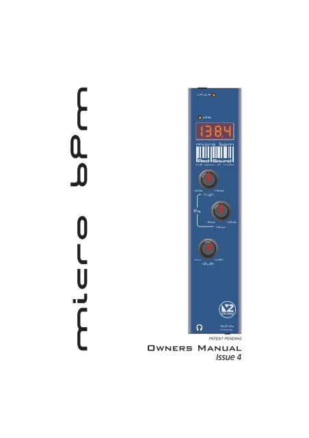
Issue 4
WARNING!<br />
AVOID USING THIS PRODUCT AT HIGH VOLUME LEVEL<br />
SETTINGS FOR EXTENDED PERIODS OF TIME!<br />
The amplifier section of the MICRO BPM is capable of delivering very<br />
high volume levels to the connected headphones which, if sustained<br />
over long periods, could cause damage to your hearing. Also, the<br />
drivers in the connected headphones may be damaged if high output<br />
levels are maintained.<br />
Always use the lowest, most comfortable volume level setting to suit<br />
the particular environment. We cannot be responsible for the<br />
improper use of this product!
CONTENTS / INTRODUCTION<br />
CONTENTS<br />
Contents & Introduction ..........................................................................<br />
Front Panel & Connectors .......................................................................<br />
Mounting & Connections .........................................................................<br />
OPERATION<br />
Powering Up ................................................................................<br />
Setting the Correct Input Level ..................................................<br />
BPM Display ................................................................................<br />
Headphone Amplifier ..................................................................<br />
Specification ................................................................................<br />
1<br />
2<br />
3<br />
4<br />
4<br />
5<br />
5<br />
6<br />
INTRODUCTION<br />
Thank you for buying the RED <strong>Sound</strong> MICRO BPM headphone amplifier/BPM counter.<br />
The MICRO BPM was designed to solve two major problems encountered by today’s DJ,<br />
namely poor headphone monitoring performance from mixing desks and having to rely on<br />
guesswork to mix and catalogue tracks. In one convenient unit, the MICRO BPM solves both<br />
these problems.<br />
At the heart of the MICRO BPM is <strong>Red</strong> <strong>Sound</strong>'s acclaimed BPM Analysis Engine (developed<br />
through groundbreaking products like the Voyager 1 and FEDERATION BPM FX), which<br />
shoulders the responsibility of calculating the tempo of the music. The powerful high quality<br />
audio amplifier, including 2 band EQ and stereo/mono switching, takes care of the monitoring.<br />
With straight-forward connections and simple setup, a compact case and three mounting<br />
options, the MICRO BPM will integrate perfectly into your live rig or studio setup.<br />
Now you can mix with confidence using the best in audio monitoring and BPM counting<br />
facilities all in one little portable box.<br />
Please read the following sections of this <strong>manual</strong> carefully to fully understand the operation of<br />
your new RED <strong>Sound</strong> MICRO BPM.<br />
PAGE<br />
1
FRONT PANEL/CONNECTORS<br />
FRONT PANEL CONTROLS AND<br />
CONNECTORS<br />
1<br />
2<br />
3<br />
Here’s a quick guide to the controls and connectors<br />
on the MICRO BPM.<br />
1 AUDIO INPUT - Connector<br />
Use the input cable ( supplied) to connect this<br />
socket to the headphone monitor output on your<br />
mixing desk.<br />
4<br />
5<br />
2 AUDIO INPUT LEVEL - Indicator<br />
Use this bi-colour red/green LED to maintain the<br />
ideal input level. See ‘ Setting the correct Input<br />
Level ’ on page 3.<br />
3 POWER IN - Connector<br />
Connect the output plug of the AC adaptor<br />
supplied with the MICRO BPM to this socket.<br />
(or optional Rechargeable Battery Pack)<br />
-<br />
+<br />
4 BEAT - Indicator<br />
This LED flashes on each beat to visually indicate<br />
the tempo.<br />
6<br />
5 BPM - Display<br />
The four digit BPM reading from the monitored<br />
audio signal will be displayed here.<br />
-<br />
+<br />
6 EQUALIZATION - Rotary controls<br />
The centre-click, High (6.5kHz) and Low (100Hz)<br />
EQ controls can be used to cut or boost the audio<br />
signal whenever adjustment is required.<br />
7<br />
7 LEVEL - Rotary control<br />
This knob controls the output level to the<br />
connected headphones.<br />
8 HEADPHONE OUT - Connector<br />
Connect the plug from your headphones to this<br />
6.3mm gold-plated socket.<br />
9 STEREO / MONO - Switch<br />
Use this switch to monitor the audio signal in<br />
stereo (up) or mono (down).<br />
/<br />
8 9<br />
PAGE<br />
2
MOUNTING/CONNECTIONS<br />
MOUNTING THE MICRO BPM<br />
You can choose from three mounting options<br />
included with the MICRO BPM.<br />
1. Rubber feet - Stick one in each corner on<br />
the underside panel for free mounting.<br />
2. Double sided adhesive pads - Stick one<br />
either side of the serial number label on the<br />
underside panel. Locate a flat, clean surface<br />
on your equipment/rig, peel-off film and press<br />
firmly into place for a permanent mounting.<br />
19” RACK MOUNT HOLE<br />
M6 SCREW<br />
BRACKET<br />
M3 SCREW<br />
(LENGTH = 5mm MAX)<br />
DJ MIXING DESK PANEL<br />
M6 NUT<br />
3. Brackets, for use with 19” rack mount<br />
holes on mixing desks - The MICRO BPM<br />
can be conveniently located on either side of a<br />
mixing desk for a semi-permanent mounting.<br />
INPUT CABLE<br />
(SUPPLIED)<br />
TO AC<br />
ADAPTOR<br />
CONNECTING THE<br />
MICRO BPM TO YOUR<br />
SYSTEM<br />
When you have chosen the best<br />
mounting option for your setup, connect<br />
the MICRO BPM into your system as<br />
follows:<br />
1. Using the input cable supplied,<br />
connect the 3.5mm plug end to the<br />
MICRO BPM socket marked ‘INPUT’ on<br />
the rear panel.<br />
HEADPHONE<br />
OUTPUT<br />
LEVEL<br />
19” RACK<br />
Hole pitch<br />
range =<br />
Min 90mm<br />
Max 240mm<br />
2. Connect the 6.3mm right-angled plug<br />
end of the cable to the headphone<br />
monitor output on your mixing desk.<br />
(Ensure that the headphone level control<br />
on the mixing desk is turned right down<br />
at this stage)<br />
3. Connect the output plug of the AC<br />
power adaptor to the MICRO BPM’s<br />
power in socket on the rear panel.<br />
4. Connect the 6.3mm plug from your<br />
headphones to the MICRO BPM socket<br />
marked on the front panel.<br />
MIXING DESK<br />
HEADPHONES<br />
/<br />
Rotate the chrome brackets<br />
to line-up with the 19”<br />
rack mounting holes on<br />
your mixing desk.<br />
PAGE<br />
3
OPERATION<br />
POWERING UP<br />
Each time power is applied to the MICRO BPM the software version fitted to the unit will be<br />
shown briefly in the main display, as in the following example:<br />
BPM<br />
Software version = 2.01<br />
[V2 BPM engine]<br />
Afterwards, the four centre bars will light to indicate the BPM engine is currently idle.<br />
BPM<br />
Four static centre bars<br />
indicate ‘IDLE’ condition<br />
(no audio beat detected)<br />
SETTING THE CORRECT INPUT LEVEL<br />
The audio input signal should always be set at the optimum level to ensure the best<br />
performance from the MICRO BPM’s headphone amplifier and BPM engine.<br />
With the MICRO BPM connected to your system as detailed on page 2, set the MICRO BPM‘s<br />
‘EQ’ controls to their centre (click) position, the ‘LEVEL’ control to minimum and the<br />
‘STEREO/MONO’ switch to the ‘STEREO’ (up position). Now play an audio track on one of<br />
your CD/Vinyl decks and ensure that the corresponding channel on the mixing desk is<br />
selected for monitoring.<br />
The MICRO BPM’s bi-colour ‘INPUT’ indicator at the top of the front panel has been designed<br />
to show four different input level conditions as follows:<br />
OFF<br />
- No audio signal present<br />
DIM GREEN - Audio signal present - level too low<br />
BRIGHT GREEN - Audio signal present - Ideal working level<br />
RED<br />
- Overload - level too high<br />
For satisfactory operation, this indicator should always be BRIGHT GREEN, occasionally<br />
flashing RED.<br />
IMPORTANT NOTE: If the indicator is continuously DIM GREEN, the BPM engine may<br />
operate erratically and the audio amplifier’s output will be low.<br />
If the indicator is continuously RED, the BPM engine cannot operate correctly and the<br />
amplifier’s output will be distorted.<br />
To set the correct input level, slowly turn up the monitor level control ON YOUR MIXING DESK<br />
until the indicator lights BRIGHT GREEN, occasionally flashing RED. Check and adjust the<br />
input level setting for different track volume levels where necessary.<br />
PAGE<br />
4
OPERATION<br />
BPM DISPLAY<br />
The main display should now show the BPM reading of the monitored audio and the ‘Beat’<br />
indicator should flash on each downbeat, as in the following example:<br />
Flashes on<br />
each beat<br />
BEAT<br />
Example reading = 138.2 BPM<br />
BPM<br />
The right-hand digit of the BPM display may fluctuate slightly as the BPM engine constantly<br />
analyses and updates the reading. Any major shift in tempo (changing the playback speed<br />
using a CD/vinyl deck’s pitch control) will be tracked and displayed in real-time by the MICRO<br />
BPM.<br />
When the input signal level drops to zero (end of track) the BPM display will flash three times<br />
and change from:<br />
3 flashes indicates<br />
‘BPM lost’ mode<br />
to...<br />
BPM<br />
BPM<br />
When further beat information is detected the BPM reading will be resumed.<br />
If beat information becomes temporarily unavailable in the monitored audio signal (quiet or<br />
complex passages, acapella styles etc.) the BPM reading and flashing Beat indication will be<br />
displayed for a period of 10 seconds (’BPM hold’ mode). This feature is designed to maintain<br />
BPM readings during short breaks in the audio track thus giving a more stable reading. If, after<br />
10 seconds beat information is still unavailable, the display will flash three times and change<br />
to ‘Idle’ mode (four centre bars) as shown above.<br />
HEADPHONE AMPLIFIER<br />
To hear the monitored audio on the connected headphones, slowly turn up the ‘LEVEL’ control<br />
on the MICRO BPM until a comfortable listening level is reached. AVOID USING HIGH LEVEL<br />
SETTINGS FOR LONG PERIODS AS DAMAGE TO HEARING OR HEADPHONES MAY<br />
OCCUR.<br />
The High and Low EQ controls on the MICRO BPM can be used to adjust the monitored<br />
sound to your individual requirements. From the centre-click null position, turn the knobs<br />
clockwise to boost or anti-clockwise to cut the specified audio frequencies.<br />
When the ‘Stereo/Mono’ switch is set to ‘Mono’(down position) the monitored audio signal will<br />
be centralised - i.e. the left and right channel signals will be equal.<br />
NOTE: this product is NOT designed for use with ‘split-cue’ headphone monitoring systems.<br />
PAGE<br />
5
SPECIFICATION<br />
SPECIFICATION<br />
BPM Counter<br />
BPM Range:<br />
Lock-in time:<br />
Accuracy:<br />
Displays:<br />
90 to 180 BPM<br />
Typically 2-4sec's(from introduction of readable beat information)<br />
Display = 0.1 BPM Internal sample rate= 3mS<br />
1 x 4 character 7 Segment (LED), Beat display (LED)<br />
Headphone Amplifier<br />
Frequency<br />
Response:<br />
Input level:<br />
Output level:<br />
High EQ:<br />
Low EQ:<br />
Stereo/Mono:<br />
20 Hz to 20kHz(+/-0.5dB)<br />
nominal 500mV (green/red input level LED)<br />
2 watts RMS (8 ohms)<br />
+/- 12dB @ 6.5kHz<br />
+/- 12dB @ 100Hz<br />
Switchable<br />
Accessories (included)<br />
Input cable:<br />
Mounting kit:<br />
1 Metre (3.5mm to 6.3mm plug),<br />
2 x chrome brackets /2xM6screws /2xM6nuts/ 2 x M3 screws,<br />
2 x double-sided adhesive pads,<br />
4 x rubber feet<br />
Connectors<br />
Audio input, Headphone output, AC power adaptor<br />
Power Supply<br />
17vDC, 320mA (RED PSU)<br />
Dimensions/Weight<br />
42(W)x195(D)x22(H)mm, Less than 0.5 Kg<br />
Optional accessory<br />
Rechargeable<br />
Battery Pack<br />
(BATT-01)<br />
Allows the MICRO BPM to be used with club installations or where<br />
a power supply may be unavailable. Provides up to 8 hours of mains-free<br />
operation. Ask your dealer/distributor for availability.<br />
* Specification and /or appearance subject to change without prior notice due to product improvement.<br />
Patent Pending<br />
PAGE<br />
6
FEDERAL COMMUNICATIONS COMMISSION<br />
RADIO FREQUENCY INTERFERENCE STATEMENT<br />
For the USA<br />
This equipment has been tested and found to comply with the limits listed for a Class B digital<br />
device, pursuant to Part 15 of the FCC Rules. These limits are designed to provide reasonable<br />
protection against harmful interference in a residential installation. This equipment generates,<br />
uses, and can radiate radio frequency energy and, if not installed and used in accordance with<br />
the instructions, may cause harmful interference to radio communications. However, there is<br />
no guarantee that interference will not occur in a particular installation. If this equipment does<br />
cause harmful interference to radio or television reception, which can be determined by turning<br />
the equipment off and on, the user is encouraged to try to correct the interference by one or<br />
more of the following measures:<br />
- Reorient or relocate the receiving antenna.<br />
- Increase the separation between the equipment and receiver.<br />
- Connect the equipment into an outlet on a circuit different from that to which the receiver is<br />
connected.<br />
- Consult the dealer or an experienced radio/TV technician for help.<br />
Unauthorized changes or modifications to this system can void the users authority to operate<br />
this equipment.<br />
This equipment requires shielded interface cables in order to meet FCC class B limit.<br />
For Europe<br />
This product complies with the requirements of European Directive 89/336/EEC<br />
CLASS B<br />
NOTICE<br />
For Canada<br />
This digital apparatus does not exceed the Class B limits for radio noise emissions set out in<br />
the Radio Interference Regulations of the Canadian Department of Communications.<br />
CLASSE B<br />
AVIS<br />
Cet appareil numerique ne depasse pas les limites de la Classe B au niveau des emissions de<br />
bruits radioelectriques fixes dans le Reglement des signaux parasites par le ministere<br />
Canadien des Communications.<br />
Copyright / Software Copyright / Design Right RED <strong>Sound</strong> <strong>Systems</strong> Ltd. 2001<br />
Printed in England
Bourne House, Cores End Road,<br />
Bourne End, Bucks. SL8 5AR. England<br />
Phone : +44 (0)1628 819191<br />
Fax : +44 (0)1628 819111