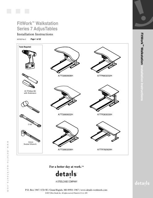
Series 7 AdjusTables FitWork™ Walkstation - Steelcase
Series 7 AdjusTables FitWork™ Walkstation - Steelcase
Series 7 AdjusTables FitWork™ Walkstation - Steelcase

Create successful ePaper yourself
Turn your PDF publications into a flip-book with our unique Google optimized e-Paper software.
FitWork <strong>Walkstation</strong><br />
<strong>Series</strong> 7 <strong>AdjusTables</strong><br />
Installation Instructions<br />
005720D Rev D Page 1 of 20<br />
Tools Required:<br />
#2 Phillips Bit<br />
with Extension<br />
A7TG660606H<br />
A7TR663232H<br />
FitWork <strong>Walkstation</strong> Installation Instructions<br />
A7TG660632H<br />
A7TR383030H<br />
7/16"<br />
www.details-worktools.com<br />
10mm<br />
Socket Wrench<br />
A7TG663206H<br />
P.O. Box 1967 / CD-5E / Grand Rapids, MI 49501-1967 / www.details-worktools.com<br />
©2007 Office Details Inc. All rights reserved. Printed in U.S.A. 2/09<br />
A7TR782929H
FitWork <strong>Walkstation</strong><br />
<strong>Series</strong> 7 <strong>AdjusTables</strong><br />
Installation Instructions<br />
005720D Rev D Page 2 of 20<br />
Worksurface Assembly<br />
1<br />
2<br />
3<br />
4<br />
Unpack and sort all components.<br />
Position top upside down on the assembly surface.<br />
Layout the left and right lift columns, lift the stretcher into each<br />
dovetail, connect loosely. (Left and right is determined when the<br />
table is standing on the base and is viewed from the front.)<br />
Once each lift column has been engaged, lightly tap each connection<br />
point with a rubber mallet 1/8-1/4 inch at a time, until completely<br />
seated. Do not completely install one lift column at a time...they<br />
must be installed incrementally.<br />
Notes:<br />
A clean, abrasion<br />
free surface will be<br />
necessary for table<br />
assembly.<br />
STRETCHER<br />
RIGHT COLUMN<br />
LEFT COLUMN<br />
STRETCHER<br />
FLUSH<br />
TOP VIEW<br />
COLUMN<br />
STRETCHER<br />
DOVETAIL<br />
DOVETAIL<br />
www.details-worktools.com<br />
5<br />
For each lift column, fold the electrical 'pig-tail' towards the center of<br />
the surface. Secure in the notch provided in each lift column.<br />
NOTCH<br />
ELECTRICAL<br />
PIGTAIL
FitWork <strong>Walkstation</strong><br />
<strong>Series</strong> 7 <strong>AdjusTables</strong><br />
Installation Instructions<br />
005720D Rev D Page 3 of 20<br />
6<br />
Locate and install each attachment plate using 4mm hex head<br />
fasteners provided. Tighten securely.<br />
4mm HEX HEAD FASTENERS<br />
ATTACHMENT PLATE<br />
7<br />
With the top still upside down on the<br />
floor, turn the base over (flipping is a 2<br />
person job) and align the attachment<br />
plates to the pre-drilled holes in the<br />
top. Loosely install one phillips head<br />
fastener in each of the 4 corners of the<br />
attachment plate. Don't install all<br />
fasteners until the unit has been<br />
operated through one cycle (Step 13).<br />
www.details-worktools.com<br />
PHILLIPS<br />
HEAD<br />
SCREW
FitWork <strong>Walkstation</strong><br />
<strong>Series</strong> 7 <strong>AdjusTables</strong><br />
Installation Instructions<br />
005720D Rev D Page 4 of 20<br />
8<br />
Remove four (4) screws on each foot.<br />
SCREW<br />
9<br />
Lower treadmill receiver onto legs and<br />
attach using four (4) screws on each<br />
leg.<br />
TREADMILL<br />
RECEIVER<br />
www.details-worktools.com
FitWork <strong>Walkstation</strong><br />
<strong>Series</strong> 7 <strong>AdjusTables</strong><br />
Installation Instructions<br />
005720D Rev D Page 5 of 20<br />
10<br />
Install control box in the<br />
predetermined location, using<br />
pre-drilled holes.<br />
CONTROL BOX<br />
www.details-worktools.com
FitWork <strong>Walkstation</strong><br />
<strong>Series</strong> 7 <strong>AdjusTables</strong><br />
Installation Instructions<br />
005720D Rev D Page 6 of 20<br />
11<br />
Locate pilot holes and place one (1) console<br />
mounting bracket assembly onto underside of<br />
worksurface. Attach bracket using three (3) screws<br />
(a). Slide console next to bracket and make sure<br />
threaded studs are inserted into slot (b). Slide<br />
other console mounting bracket next to<br />
console making sure holes in bracket are<br />
lined up with pilot holes on worksurface (c).<br />
Secure bracket to worksurface using three (3)<br />
screws (d). Secure brackets to each side<br />
of console using two (2) nuts and two (2)<br />
flat washers (e).<br />
b<br />
SHOULDER<br />
WASHER<br />
CONSOLE<br />
c<br />
SHOULDER<br />
WASHER<br />
www.details-worktools.com<br />
FLAT WASHER<br />
NUT<br />
a<br />
e<br />
SCREW<br />
CONSOLE MOUNTING<br />
BRACKET ASSEMBLY<br />
d<br />
SCREW
FitWork <strong>Walkstation</strong><br />
<strong>Series</strong> 7 <strong>AdjusTables</strong><br />
Installation Instructions<br />
005720D Rev D Page 7 of 20<br />
12<br />
Install the wire management<br />
cableway on the underside of<br />
the worksurface about 5" in<br />
front of the control box.<br />
5"<br />
WIRE MANAGER<br />
13<br />
Connect the cables to each lift column and connect the<br />
terminal end to the control box. Route these cables in the<br />
wire management cableway provided. Refer to the Wiring<br />
Guide for more information.<br />
For best wire management, connect lift columns to the<br />
closest port on the control box.<br />
www.details-worktools.com<br />
PORT #1<br />
PORT #2
FitWork <strong>Walkstation</strong><br />
<strong>Series</strong> 7 <strong>AdjusTables</strong><br />
Installation Instructions<br />
005720D Rev D Page 8 of 20<br />
14<br />
Install the cable located on the back of the console<br />
into the control box as shown. Store extra cable<br />
length into wire manager.<br />
CONTROL BOX<br />
CABLE FROM CONSOLE<br />
www.details-worktools.com<br />
15<br />
Install the plug into the control box. Secure the cord to the<br />
control box using the molded-in clip. Plug the cord into an<br />
outlet and check for binding, then lower to the bottom and<br />
unplug unit. Install the remaining fasteners in each of the<br />
remaining holes and tighten ALL screws securely.<br />
Do not over tighten.<br />
PLUG<br />
CONTROL BOX<br />
MOLDED CLIP
FitWork <strong>Walkstation</strong><br />
<strong>Series</strong> 7 <strong>AdjusTables</strong><br />
Installation Instructions<br />
005720D Rev D Page 9 of 20<br />
16<br />
Carefully turn the table over (2 person operation).<br />
NOTE: Do NOT use either lift column as a brace<br />
when turning the table over as this may cause<br />
binding. The top must be lifted free, rotated and<br />
set down carefully.<br />
17<br />
Install treadmill. Align treadmill with unit as shown. Make<br />
sure the two (2) treadmill feet are inserted into the two (2)<br />
holes in the treadmill receiver.<br />
NOTE: The holes in the treadmill<br />
receiver are for the treadmill feet,<br />
not the treadmill wheels.<br />
TREADMILL FOOT<br />
www.details-worktools.com<br />
HOLE IN TREADMILL<br />
RECEIVER<br />
TREADMILL
FitWork <strong>Walkstation</strong><br />
<strong>Series</strong> 7 <strong>AdjusTables</strong><br />
Installation Instructions<br />
005720D Rev D Page 10 of 20<br />
18<br />
Locate back left of treadmill and plug in signal cable as indicated<br />
(a). Locate back center of console and plug in other end of<br />
signal cable as indicated (b). Plug the cord of the table and the<br />
treadmill into an outlet. Make sure treadmill is turned on (c).<br />
NOTE for (a) & (b): Be sure to secure signal cable to the console<br />
and treadmill with the screws integral to the cable connector.<br />
This will ensure a good connection.<br />
b<br />
SIGNAL CABLE<br />
CONSOLE<br />
www.details-worktools.com<br />
c<br />
a<br />
REAR OF<br />
TREADMILL<br />
SIGNAL CABLE<br />
CONSOLE<br />
View from Underneath<br />
Worksurface
FitWork <strong>Walkstation</strong><br />
<strong>Series</strong> 7 <strong>AdjusTables</strong><br />
Installation Instructions<br />
005720D Rev D Page 11 of 20<br />
19 Pull console forward.<br />
20<br />
Connect safety key to magnetic<br />
attachment area on<br />
front of keypad.<br />
21<br />
Before use, the table must be completely leveled, front-to back and side-to-side.<br />
Coordinating the Lifting Columns<br />
Prior to initial use of the height adjustment function you must "synchronize the system".<br />
The installers who setup the worksurface may have already done so, but it's OK to repeat this function.<br />
Synchronize the System<br />
• Press the Down arrow until the worksurface comes to a stop at the lowest position.<br />
• Release the Down arrow.<br />
• Press and hold the down arrow for approximately 5 seconds while the table<br />
synchronizes itself. The surface will lower itself approximately 5mm, then rise<br />
approximately 5mm and finally settle back to its lowest position.<br />
NOTE: It may be necessary to repeat the synchronization process more than once.<br />
After performing this function, the movement of all lift columns connected is coordinated.<br />
In the unlikely event that an error occurs, reset the control unit by pressing the Up and<br />
Down buttons at the same time for 5 seconds. Then repeat the synchronizing sequence<br />
as previously outlined above.<br />
22<br />
Raise or lower desk height<br />
by pressing buttons on the<br />
console.<br />
www.details-worktools.com<br />
GLIDE<br />
NOTE: Guidelines on Moving the Table, see page 19.<br />
For Wiring Guide, see page 20.
FitWork Sit-to-<strong>Walkstation</strong><br />
<strong>Series</strong> 7 <strong>AdjusTables</strong><br />
Installation Instructions<br />
005720D Rev D Page 12 of 20<br />
Sit-to-<strong>Walkstation</strong> Worksurface Assembly<br />
1<br />
2<br />
Repeat steps 1 through 6 on pages 2 and 3.<br />
With the top still upside down on the floor, turn the<br />
base over (flipping is a 2 person job) and align the<br />
attachment plates to the pre-drilled holes in the top.<br />
Loosely install one phillips head fastener in each of<br />
the 4 corners of the attachment plate. Don't install<br />
all fasteners until the unit has been operated<br />
through one cycle (Step 18).<br />
PHILLIPS<br />
HEAD<br />
SCREW<br />
www.details-worktools.com<br />
If you want the treadmill placed on<br />
the left side, use these pilot holes<br />
for attaching legs.<br />
Underside of Worksurface<br />
REAR OF WORKSURFACE<br />
FRONT OF WORKSURFACE<br />
If you want the treadmill placed on<br />
the right side, use these pilot holes<br />
for attaching legs.
FitWork Sit-to-<strong>Walkstation</strong><br />
<strong>Series</strong> 7 <strong>AdjusTables</strong><br />
Installation Instructions<br />
005720D Rev D Page 13 of 20<br />
3<br />
Remove four (4) screws on one foot on the side<br />
of the table where the treadmill will be installed.<br />
(left side installation shown).<br />
SCREW<br />
SIT-WALK<br />
TREADMILL RECEIVER<br />
4<br />
Lower treadmill receiver onto leg and<br />
attach using four (4) screws.<br />
SCREW<br />
www.details-worktools.com
FitWork Sit-to-<strong>Walkstation</strong><br />
<strong>Series</strong> 7 <strong>AdjusTables</strong><br />
Installation Instructions<br />
005720D Rev D Page 14 of 20<br />
5<br />
6<br />
Repeat steps 10 thru 13 on pages 5, 6 & 7.<br />
Install the controller to the underside of the worksurface<br />
towards the middle of the worksurface as shown.<br />
www.details-worktools.com
FitWork Sit-to-<strong>Walkstation</strong><br />
<strong>Series</strong> 7 <strong>AdjusTables</strong><br />
Installation Instructions<br />
005720D Rev D Page 15 of 20<br />
7<br />
Install the wire keepers for the control wire. Peel off paper<br />
backing and stick to worksurface. Place wire into each wire<br />
keeper.<br />
Repeat steps 14 & 15 on page 8.<br />
PAPER BACKING<br />
WIRE KEEPER<br />
CONTROL<br />
WIRE<br />
www.details-worktools.com
FitWork Sit-to-<strong>Walkstation</strong><br />
<strong>Series</strong> 7 <strong>AdjusTables</strong><br />
Installation Instructions<br />
005720D Rev D Page 16 of 20<br />
8<br />
Carefully turn the table over (2 person operation).<br />
NOTE: Do NOT use either lift column as a brace<br />
when turning the table over as this may cause<br />
binding. The top must be lifted free, rotated and<br />
set down carefully.<br />
www.details-worktools.com
FitWork Sit-to-<strong>Walkstation</strong><br />
<strong>Series</strong> 7 <strong>AdjusTables</strong><br />
Installation Instructions<br />
005720D Rev D Page 17 of 20<br />
9<br />
10<br />
Install treadmill. Align treadmill with unit as shown. Make<br />
sure the two (2) treadmill feet are inserted into the two (2)<br />
holes in the treadmill receiver.<br />
NOTE: The holes in the treadmill receiver are for<br />
the treadmill feet, not the treadmill wheels.<br />
Plug in cable from back of treadmill to back of console as<br />
shown on step 18 on page 10. Also, plug cord of the table<br />
and the treadmill into an outlet & make sure the treadmill<br />
is on as shown on step 18 on page 10.<br />
TREADMILL FOOT<br />
www.details-worktools.com<br />
HOLE IN TREADMILL<br />
RECEIVER<br />
TREADMILL
FitWork Sit-to-<strong>Walkstation</strong><br />
<strong>Series</strong> 7 <strong>AdjusTables</strong><br />
Installation Instructions<br />
005720D Rev D Page 18 of 20<br />
11 Pull console forward.<br />
Connect safety key to magnetic<br />
attachment area on<br />
front of keypad.<br />
12<br />
13<br />
Before use, the table must be completely leveled, front-to back and side-to-side.<br />
Coordinating the Lifting Columns<br />
Prior to initial use of the height adjustment function you must "synchronize the system".<br />
The installers who setup the worksurface may have already done so, but it's OK to repeat this function.<br />
Synchronize the System<br />
• Press the Down arrow until the worksurface comes to a stop at the lowest position.<br />
• Release the Down arrow.<br />
• Press and hold the down arrow for approximately 5 seconds while the table<br />
synchronizes itself. The surface will lower itself approximately 5mm, then rise<br />
approximately 5mm and finally settle back to its lowest position.<br />
NOTE: It may be necessary to repeat the synchronization process more than once.<br />
After performing this function, the movement of all lift columns connected is coordinated.<br />
In the unlikely event that an error occurs, reset the control unit by pressing the Up and<br />
Down buttons at the same time for 5 seconds. Then repeat the synchronizing sequence<br />
as previously outlined above.<br />
14 Raise or lower desk height<br />
by pressing buttons on the<br />
console.<br />
www.details-worktools.com<br />
GLIDE<br />
NOTE: Guidelines on Moving the Table, see page 19.<br />
For Wiring Guide, see page 20.
FitWork Sit-to-<strong>Walkstation</strong><br />
<strong>Series</strong> 7 <strong>AdjusTables</strong><br />
Installation Instructions<br />
005720D Rev D Page 19 of 20<br />
Guidelines on Moving the Table<br />
1<br />
2<br />
3<br />
4<br />
When possible, the tables should be moved in a horizontal (flat) position.<br />
If the table must be moved vertically (i.e. standing on a pallet), care must be taken to ensure no side pressure<br />
is placed on any of the legs as it is tipped into position, during transport, and when tipped off the pallet at the<br />
new location.<br />
Before in use in the location, the table must again be completely leveled side-to-side and front-to-back. Failure<br />
to do so may cause binding of the leg(s) and failure to operate properly.<br />
After moving, the legs must be re-synchronized by holding 'down' arrow on the controller while the legs seek<br />
to level themselves.<br />
FOOT<br />
GLIDES<br />
CONTROL BOX<br />
ATTACHMENT<br />
PLATE<br />
www.details-worktools.com<br />
STRETCHER
FitWork Sit-to-<strong>Walkstation</strong><br />
<strong>Series</strong> 7 <strong>AdjusTables</strong><br />
Installation Instructions<br />
005720D Rev D Page 20 of 20<br />
Wiring Guide<br />
1<br />
When connecting cables as stated in Step 13, use this guide<br />
as a reference.<br />
2<br />
Connect the cables from the Lift Columns to the cables<br />
provided. The other end should be connected to the Control<br />
Box. Repeat this for each leg.<br />
3<br />
Connect the end of the Controller cable into the Control Box.<br />
4<br />
Follow Steps 13, 14, 15 & 18 to complete the wiring installation.<br />
5<br />
Once you have completed the wiring, use the Wire<br />
Management Cableways to hold all the cables and minimize<br />
possible entanglements.<br />
FOOT<br />
GLIDES<br />
NOTE: Cableways and vertical wire management solutions are<br />
also available from Details. Contact us for more information.<br />
LEFT LIFT<br />
COLUMN<br />
CONTROL BOX<br />
RIGHT LIFT<br />
COLUMN<br />
ATTACHMENT<br />
PLATE<br />
www.details-worktools.com<br />
CONTROL<br />
• Never attach wires to the<br />
legs or stretcher in any way.