

P216, P218 P220, P224 Performer Series - Cummins Onan
P216, P218 P220, P224 Performer Series - Cummins Onan
P216, P218 P220, P224 Performer Series - Cummins Onan

Create successful ePaper yourself
Turn your PDF publications into a flip-book with our unique Google optimized e-Paper software.
Starting System<br />
. ELECTRIC STARTER<br />
Normally the starter will require little or no service other<br />
. than possible brush replacement. However, if through<br />
accident or misuse, the starter requires service or<br />
overhaul, the following will provide the information<br />
necessary to perform this service.<br />
Remove both battery cables from battery. Disconnect<br />
ground cable first.<br />
Disconnect battery cable and electrical lead wires<br />
from starter.<br />
Remove starter motor.<br />
Service<br />
When starting engine, note starter motor action. The<br />
pinion gear should mesh quickly with flywheel ring gear<br />
and spin engine. Once engine starts and solenoid<br />
opens, the starter should disengage and stop. If starter<br />
cranks engine slow, or not at all, check start circuit<br />
components. Failure to crank is normally caused by low<br />
battery charge, defective battery cables, corroded or<br />
poor connections, or low temperatures. If after checking<br />
these variables, starter continues to crank slowly, starter<br />
must be removed and repaired.<br />
Starter Removal<br />
-1 Accidental starting of the engine can<br />
result in severe personal injury or<br />
death. Disconnect the negative battery cable andspark<br />
plug wires while servicing engine, controls, or associated<br />
equipment.<br />
Starter Disassembly<br />
1.<br />
2.<br />
3.<br />
4.<br />
5.<br />
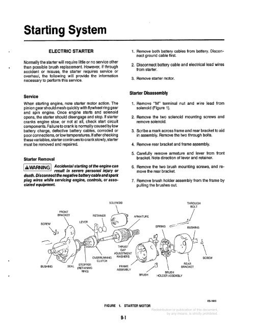
Remove “M” terminal nut and wire lead from<br />
solenoid (Figure 1).<br />
Remove the two solenoid mounting screws and<br />
remove solenoid.<br />
Scribe a mark across frame and rear bracket to aid<br />
in assembly. Remove the two through bolts.<br />
Remove rear bracket and frame assembly.<br />
Carefully remove armature and lever from front<br />
bracket. Note direction of lever and retainer.<br />
6. Remove the two brush mounting screws, and remove<br />
the rear bracket.<br />
7. Remove brush holder assembly from the frame by<br />
pulling the brushes out.<br />
FRONT<br />
SOLENOID<br />
\<br />
THROUGH<br />
BOLT<br />
/<br />
’ STOPPER<br />
BUSHING SEAL (RETAINING<br />
RING)<br />
ADJUSTMENT<br />
FRAME<br />
ASSEMBLY<br />
/ -<br />
BRUSH<br />
REAR<br />
,B \ BRACKET<br />
BRUSH<br />
HOLDER ASSEMBLY<br />
C<br />
.-==<br />
-i<br />
\<br />
SCREW<br />
FIGURE 1. STARTER MOTOR<br />
ES-1665<br />
9-1


