

P216, P218 P220, P224 Performer Series - Cummins Onan
P216, P218 P220, P224 Performer Series - Cummins Onan
P216, P218 P220, P224 Performer Series - Cummins Onan

Create successful ePaper yourself
Turn your PDF publications into a flip-book with our unique Google optimized e-Paper software.
Tappet Adjustment<br />
The engine is equipped with adjustable valve tappets.<br />
The valve tappet clearance should be checked and<br />
adjusted as specified in the Periodic Maintenance<br />
Schedule (located in the Operator's Manual). Adjust the<br />
valve clearance only when engine is at ambient temperature.<br />
Proceed as follows:<br />
1. Remove ignition key to prevent accidental starting.<br />
2. Remove all parts necessary to gain access to valve<br />
tappets.<br />
3. Remove spark plugs to ease the task of turning the<br />
engine over by hand.<br />
4. Place a socket wrench on the flywheel capscrew<br />
and rotate the crankshaft in a clockwise direction<br />
until the left intake valve (viewed from flywheel end)<br />
opens and closes. Continue turning the crankshaft<br />
until theTC markon the flywheel is lined up with the<br />
TC mark on the gear cover. This should place the<br />
left piston (#I) at the top of its compression stroke.<br />
Verify that the left intake and exhaust valves are<br />
closed and there is no pressure on the valve lifters.<br />
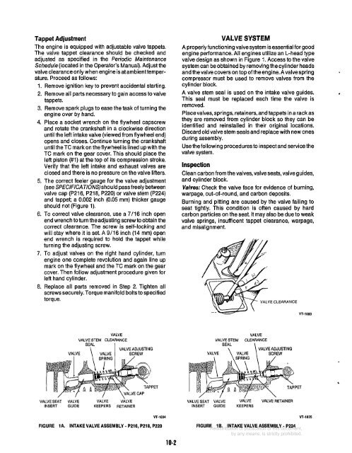
5. The correct feeler gauge for the valve adjustment<br />
(see SPE ClFlCATI0NS)should pass freely between<br />
valve cap (<strong>P216</strong>, <strong>P218</strong>, <strong>P220</strong>) or valve stem (<strong>P224</strong>)<br />
and tappet; a 0.002 inch (0.05 mm) thicker gauge<br />
should not (Figure 1).<br />
6. To correct valve clearance, use a 7/16 inch open<br />
end wrench to turn theadjusting screw toobtain the<br />
correct clearance. The screw is self-locking and<br />
will stay where it is set. A 9/16 inch (14 mm) open<br />
end wrench is required to hold the tappet while<br />
turning the adjusting screw.<br />
7. To adjust valves on the right hand cylinder, turn<br />
engine one complete revolution and again line up<br />
mark on the flywheel and the TC mark on the gear<br />
cover. Then follow adjustment procedure given for<br />
left hand cylinder.<br />
8. Replace all parts removed in Step 2. Tighten all<br />
screws securely. Torque manifold bolts to specified<br />
torque.<br />
VALVE SYSTEM<br />
A properly functioning valvesystem is essential for good<br />
engine performance. All engines utilize an L-head type<br />
valve design as shown in Figure 1. Access to the valve<br />
system can be obtained by removing the cylinder heads<br />
and thevalve coverson topoftheengine.Avalvespring<br />
compressor must be used to remove valves from the<br />
cy1 inder block.<br />
A valve stem seal is used on the intake valve guides.<br />
This seal must be replaced each time the valve is<br />
removed.<br />
Place valves, springs, retainers, and tappets in a rack as<br />
they are removed from cylinder block so they can be<br />
identified and reinstalled in their original locations.<br />
Discard old valve stem seals and replace with new ones<br />
during assembly.<br />
Use the following procedures to inspect and service the<br />
valve system.<br />
Inspection<br />
Clean carbon from thevalves, valve seats, valve guides,<br />
and cylinder block.<br />
Valves: Check the valve face for evidence of burning,<br />
warpage, out-of-round, and carbon deposits.<br />
Burning and pitting are caused by the valve failing to<br />
seat tightly. This condition is often caused by hard<br />
carbon particles on the seat It may also be due to weak<br />
valve springs, insufficent tappet clearance, warpage,<br />
and misalignment.<br />
VALVE<br />
VALVE STEM CLEARANCE<br />
SEAL<br />
I VALVE ADJUSTING<br />
VALVE \ VALVE SCREW<br />
VALVE<br />
VALVE STEM CLEARANCE<br />
SEAL<br />
\ \ VALVE ADJUSTING<br />
PET<br />
c<br />
VALVE SEAT VALVE VALVE VALVE<br />
INSERT GUIDE KEEPERS RETAINER<br />
VALVE SEAT VALVE VALVE VALVE RETAINER<br />
INSERT GUIDE KEEPERS<br />
FIGURE 1A.<br />
VT-1034<br />
INTAKE VALVE ASSEMBLY - <strong>P216</strong>, <strong>P218</strong>, <strong>P220</strong><br />
FIGURE 1B. INTAKE VALVE ASSEMBLY - <strong>P224</strong><br />
WIT-1035<br />
10-2


