Caution: This document contains mixed page sizes ... - Cummins Onan
Caution: This document contains mixed page sizes ... - Cummins Onan
Caution: This document contains mixed page sizes ... - Cummins Onan

Create successful ePaper yourself
Turn your PDF publications into a flip-book with our unique Google optimized e-Paper software.
GASOLINE—MODELS HGJAB / HGJAC<br />
Note: The installer is responsible for meeting all<br />
CARB and EPA evaporative emissions requirements<br />
that may be applicable for the fuel system.<br />
Fuel Tank<br />
Do not change or remove the fuel fill tube, fill limiter<br />
vent, vapor canister, vapor lines, filler cap or any<br />
other part of the fuel system without the express approval<br />
of the vehicle chassis manufacturer. Modifications<br />
must conform with applicable sections of the<br />
Code of Federal Regulations, Titles 40 and 49, and<br />
other standards.<br />
<strong>Onan</strong> recommends a separate fuel pickup tube or a<br />
separate fuel tank for the genset. The genset must<br />
never be connected to the fuel supply line of the<br />
vehicle engine—either to a high-pressure system<br />
(pump in tank), which can overpressurize the genset<br />
fuel system, or to a vacuum system (pump on<br />
engine), which can cause the genset to starve for<br />
fuel. Some vehicle chassis manufacturers allow<br />
connections to the fuel return line on high pressure<br />
fuel systems. Contact the vehicle chassis manufacturer<br />
for approval. Fuel line pressure at the point<br />
where the genset is connected must not exceed<br />
1-1/2 psi under any condition.<br />
WARNING Excessive fuel pressure can flood<br />
the genset causing a fire. Genset fuel supply<br />
line pressure must not exceed 1-1/2 psi under<br />
any condition.<br />
double-flare hose beads (Figure 4-4). <strong>This</strong> is<br />
recommended for all tubing and fittings.<br />
• Flexible Hose: Use 1/4 in I. D. fuel hose that<br />
meets applicable standards for evaporative<br />
emissions.<br />
CAUTION When connecting fuel hoses,<br />
only use soap-free lubricants such as<br />
WD40, which runs through fuel without<br />
leaving residues that can clog fuel jets.<br />
• Hose Clamps: Use stainless steel stepless ear<br />
clamps (Figure 4-4). <strong>Onan</strong> P/N 0503-1951-11,<br />
Oetiker P/N 16700011 or equivalent are recommended.<br />
Routing Fuel Lines<br />
Route the fuel line along bulkheads and frame<br />
members such that it is protected, and at or above<br />
the top of the fuel tank to reduce siphoning if a line<br />
breaks or a hose comes off. The entire length of a<br />
fuel line must be visible for inspection and accessible<br />
for replacement.<br />
Support fuel lines to restrain movement and prevent<br />
chaffing or contact with sharp edges, electrical wiring<br />
and hot exhaust parts.<br />
WARNING Electric arcs can ignite gasoline<br />
leading to severe personal injury or death. Do<br />
not run wiring and fuel lines together.<br />
The maximum fuel pump lift is 36 inches (914 mm).<br />
Terminate the genset fuel pickup above the vehicle<br />
engine pickup in the supply tank to keep the genset<br />
from running the vehicle out of fuel.<br />
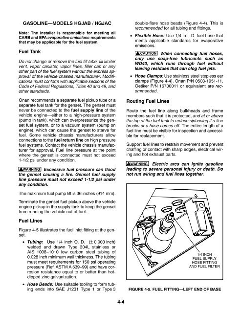
Fuel Lines<br />
Figure 4-5 illustrates the fuel inlet fitting at the genset.<br />
• Tubing: Use 1/4 inch O. D. (± 0.003 inch)<br />
welded and drawn Type 304L stainless or<br />
AISI 1008−1010 low carbon steel tubing of<br />
0.028 inch minimum wall thickness. The tubing<br />
must meet requirements for 150 psi operating<br />
pressure (Ref. ASTM A 539−99) and have corrosion<br />
resistance equal to or better than hotdipped<br />
zinc galvanization.<br />
• Hose Beads: Use suitable tooling to form tubing<br />
ends into SAE J1231 Type 1 or Type 3<br />
1/4 INCH<br />
FUEL SUPPLY<br />
HOSE FITTING<br />
AND FUEL FILTER<br />
FIGURE 4-5. FUEL FITTING—LEFT END OF BASE<br />
4-4