Caution: This document contains mixed page sizes ... - Cummins Onan
Caution: This document contains mixed page sizes ... - Cummins Onan
Caution: This document contains mixed page sizes ... - Cummins Onan

You also want an ePaper? Increase the reach of your titles
YUMPU automatically turns print PDFs into web optimized ePapers that Google loves.
REMOTE CONTROL CONNECTIONS<br />
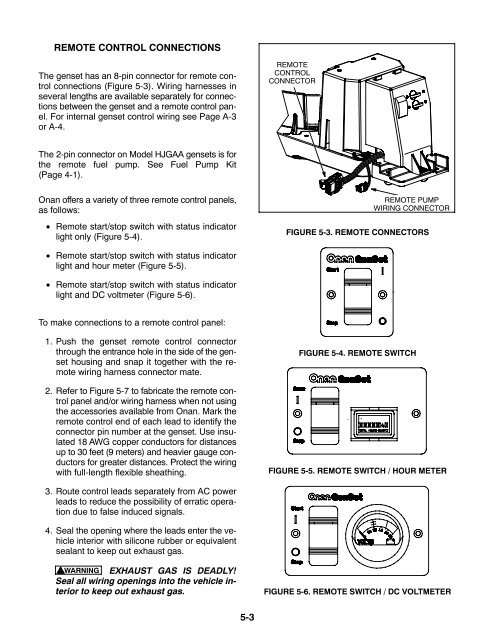
The genset has an 8-pin connector for remote control<br />
connections (Figure 5-3). Wiring harnesses in<br />
several lengths are available separately for connections<br />
between the genset and a remote control panel.<br />
For internal genset control wiring see Page A-3<br />
or A-4.<br />
REMOTE<br />
CONTROL<br />
CONNECTOR<br />
The 2-pin connector on Model HJGAA gensets is for<br />
the remote fuel pump. See Fuel Pump Kit<br />
(Page 4-1).<br />
<strong>Onan</strong> offers a variety of three remote control panels,<br />
as follows:<br />
• Remote start/stop switch with status indicator<br />
light only (Figure 5-4).<br />
REMOTE PUMP<br />
WIRING CONNECTOR<br />
FIGURE 5-3. REMOTE CONNECTORS<br />
• Remote start/stop switch with status indicator<br />
light and hour meter (Figure 5-5).<br />
• Remote start/stop switch with status indicator<br />
light and DC voltmeter (Figure 5-6).<br />
To make connections to a remote control panel:<br />
1. Push the genset remote control connector<br />
through the entrance hole in the side of the genset<br />
housing and snap it together with the remote<br />
wiring harness connector mate.<br />
2. Refer to Figure 5-7 to fabricate the remote control<br />
panel and/or wiring harness when not using<br />
the accessories available from <strong>Onan</strong>. Mark the<br />
remote control end of each lead to identify the<br />
connector pin number at the genset. Use insulated<br />
18 AWG copper conductors for distances<br />
up to 30 feet (9 meters) and heavier gauge conductors<br />
for greater distances. Protect the wiring<br />
with full-length flexible sheathing.<br />
FIGURE 5-4. REMOTE SWITCH<br />
FIGURE 5-5. REMOTE SWITCH / HOUR METER<br />
3. Route control leads separately from AC power<br />
leads to reduce the possibility of erratic operation<br />
due to false induced signals.<br />
4. Seal the opening where the leads enter the vehicle<br />
interior with silicone rubber or equivalent<br />
sealant to keep out exhaust gas.<br />
WARNING EXHAUST GAS IS DEADLY!<br />
Seal all wiring openings into the vehicle interior<br />
to keep out exhaust gas.<br />
FIGURE 5-6. REMOTE SWITCH / DC VOLTMETER<br />
5-3