Caution: This document contains mixed page sizes ... - Cummins Onan
Caution: This document contains mixed page sizes ... - Cummins Onan
Caution: This document contains mixed page sizes ... - Cummins Onan

You also want an ePaper? Increase the reach of your titles
YUMPU automatically turns print PDFs into web optimized ePapers that Google loves.
HIGH PRESSURE PROPANE SUPPLY<br />
(LIQUID WITHDRAWAL)<br />
The Standard for the Storage and Handling of Liquified<br />
Petroleum Gases (NFPA No. 58) should be<br />
used as a guide for the installation of the propane<br />
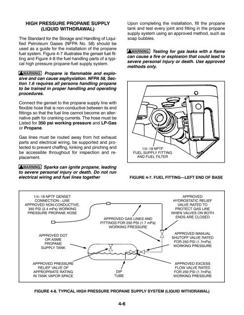
fuel system. Figure 4-7 illustrates the genset fuel fitting<br />
and Figure 4-8 the fuel handling parts of a typical<br />
high pressure propane-fuel supply system.<br />
WARNING Propane is flammable and explosive<br />
and can cause asphyxiation. NFPA 58, Section<br />
1.6 requires all persons handling propane<br />
to be trained in proper handling and operating<br />
procedures.<br />
Upon completing the installation, fill the propane<br />
tank and test every joint and fitting in the propane<br />
supply system using an approved method, such as<br />
soap bubbles.<br />
WARNING Testing for gas leaks with a flame<br />
can cause a fire or explosion that could lead to<br />
severe personal injury or death. Use approved<br />
methods only.<br />
Connect the genset to the propane supply line with<br />
flexible hose that is non-conductive between its end<br />
fittings so that the fuel line cannot become an alternative<br />
path for cranking currents. The hose must be<br />
Listed for 350 psi working pressure and LP-Gas<br />
or Propane.<br />
Gas lines must be routed away from hot exhaust<br />
parts and electrical wiring, be supported and protected<br />
to prevent chaffing, kinking and pinching and<br />
be accessible throughout for inspection and replacement.<br />
WARNING Sparks can ignite propane, leading<br />
to severe personal injury or death. Do not run<br />
electrical wiring and fuel lines together<br />
1/4−18 NPTF<br />
FUEL SUPPLY FITTING<br />
AND FUEL FILTER<br />
FIGURE 4-7. FUEL FITTING—LEFT END OF BASE<br />
1/4−18 NPTF GENSET<br />
CONNECTION—USE<br />
APPROVED NON-CONDUCTIVE,<br />
350 PSI (2.4 mPa) WORKING<br />
PRESSURE PROPANE HOSE<br />
APPROVED DOT<br />
OR ASME<br />
PROPANE<br />
SUPPLY TANK<br />
APPROVED GAS LINES AND<br />
FITTINGS FOR 250 PSI (1.7 mPa)<br />
WORKING PRESSURE<br />
APPROVED<br />
HYDROSTATIC RELIEF<br />
VALVE RATED TO<br />
PROTECT GAS LINE<br />
WHEN VALVES ON BOTH<br />
ENDS ARE CLOSED<br />
APPROVED MANUAL<br />
SHUTOFF VALVE RATED<br />
FOR 250 PSI (1.7mPa)<br />
WORKING PRESSURE<br />
APPROVED PRESSURE<br />
RELIEF VALVE OF<br />
APPROPRIATE RATING<br />
IN TANK VAPOR SPACE<br />
DIP<br />
TUBE<br />
APPROVED EXCESS<br />
FLOW VALVE RATED<br />
FOR 250 PSI (1.7mPa)<br />
WORKING PRESSURE<br />
FIGURE 4-8. TYPICAL HIGH PRESSURE PROPANE SUPPLY SYSTEM (LIQUID WITHDRAWAL)<br />
4-6