Caution: This document contains mixed page sizes ... - Cummins Onan
Caution: This document contains mixed page sizes ... - Cummins Onan
Caution: This document contains mixed page sizes ... - Cummins Onan

Create successful ePaper yourself
Turn your PDF publications into a flip-book with our unique Google optimized e-Paper software.
5. Electrical Connections<br />
To prevent accidental starting of the genset during<br />
installation, do not connect the battery cables at the<br />
battery until so instructed in STARTUP (Page 6-2).<br />
WARNING Accidental starting of the genset<br />
can cause severe personal injury or death. Do<br />
not connect the starting battery until so<br />
instructed in STARTUP.<br />
AC POWER OUTPUT CONNECTIONS<br />
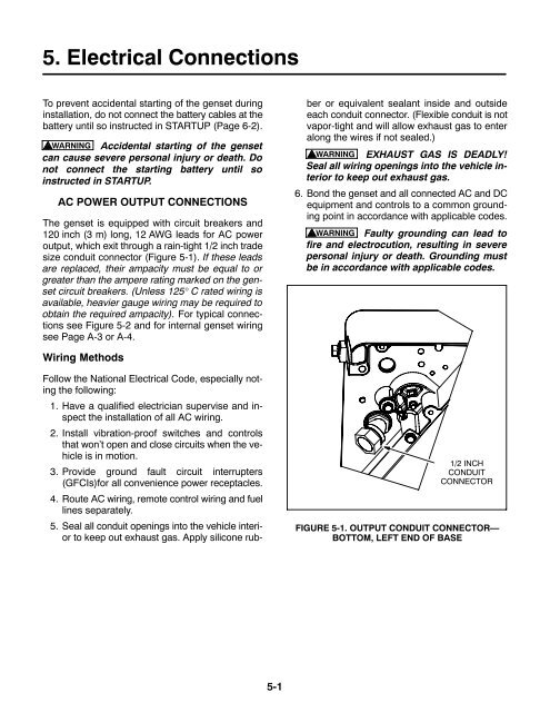
The genset is equipped with circuit breakers and<br />
120 inch (3 m) long, 12 AWG leads for AC power<br />
output, which exit through a rain-tight 1/2 inch trade<br />
size conduit connector (Figure 5-1). If these leads<br />
are replaced, their ampacity must be equal to or<br />
greater than the ampere rating marked on the genset<br />
circuit breakers. (Unless 125° C rated wiring is<br />
available, heavier gauge wiring may be required to<br />
obtain the required ampacity). For typical connections<br />
see Figure 5-2 and for internal genset wiring<br />
see Page A-3 or A-4.<br />
Follow the National Electrical Code, especially noting<br />
the following:<br />
1. Have a qualified electrician supervise and inspect<br />
the installation of all AC wiring.<br />
2. Install vibration-proof switches and controls<br />
that won’t open and close circuits when the vehicle<br />
is in motion.<br />
3. Provide ground fault circuit interrupters<br />
(GFCIs)for all convenience power receptacles.<br />
4. Route AC wiring, remote control wiring and fuel<br />
lines separately.<br />
5. Seal all conduit openings into the vehicle interior<br />
to keep out exhaust gas. Apply silicone rubber<br />
or equivalent sealant inside and outside<br />
each conduit connector. (Flexible conduit is not<br />
vapor-tight and will allow exhaust gas to enter<br />
along the wires if not sealed.)<br />
WARNING EXHAUST GAS IS DEADLY!<br />
Seal all wiring openings into the vehicle interior<br />
to keep out exhaust gas.<br />
6. Bond the genset and all connected AC and DC<br />
equipment and controls to a common grounding<br />
point in accordance with applicable codes.<br />
WARNING Faulty grounding can lead to<br />
fire and electrocution, resulting in severe<br />
personal injury or death. Grounding must<br />
be in accordance with applicable codes.<br />
Wiring Methods<br />
1/2 INCH<br />
CONDUIT<br />
CONNECTOR<br />
FIGURE 5-1. OUTPUT CONDUIT CONNECTOR—<br />
BOTTOM, LEFT END OF BASE<br />
5-1