TM 3-4240-334-20&P
TM 3-4240-334-20&P
TM 3-4240-334-20&P

You also want an ePaper? Increase the reach of your titles
YUMPU automatically turns print PDFs into web optimized ePapers that Google loves.
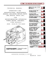
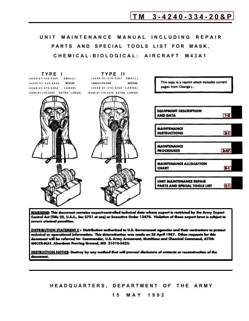
<strong>TM</strong> 3-<strong>4240</strong>-<strong>334</strong>-20&P<br />
UNIT MAINTENANCE MANUAL INCLUDING REPAIR<br />
PARTS AND SPECIAL TOOLS LIST FOR MASK,<br />
CHEMICAL-BIOLOGICAL: AIRCRAFT M43A1<br />
TYPE I<br />
TYPE II<br />
(<strong>4240</strong>-01-319-5365 SMALL) (<strong>4240</strong>-01-319-5367 SMALL)<br />
(<strong>4240</strong>-01-320-8949 MEDIUM) (<strong>4240</strong>-01-319-5368 MEDIUM)<br />
(<strong>4240</strong>-01-319-5364 LARGE) (<strong>4240</strong>-01-319-5369 LARGE)<br />
(<strong>4240</strong>-01-319-5366 EXTRA LARGE) (<strong>4240</strong>-01-319-5370 EXTRA LARGE)<br />
HEADQUARTERS, DEPAR<strong>TM</strong>ENT OF THE ARMY<br />
15 MAY 1992
<strong>TM</strong> 3-<strong>4240</strong>-<strong>334</strong>-20&P<br />
C1<br />
C HANGE<br />
No. 1<br />
HEADQUARTERS<br />
DEPAR<strong>TM</strong>ENT OF THE ARMY<br />
Washington, DC 15 June 1992<br />
UNIT MAINTENANCE MANUAL INCLUDING REPAIR<br />
PARTS AND SPECIAL TOOLS LIST FOR<br />
MASK, CHEMICAL-BIOLOGICAL: AIRCRAFT, M43A1<br />
1. The purpose of this change is to add the authentication page<br />
to the manual.<br />
2. New material is indicated by a vertical bar in the margin of<br />
the page.<br />
3. Remove old pages and insert new pages as indicated below.<br />
Remove Page<br />
None<br />
Insert Page<br />
Authentication Page<br />
(in front of back cover)<br />
4. File this sheet after the title page for reference purposes.<br />
MILTON H. HAMILTON<br />
Administrative Assistant to the<br />
Secretary of the Army<br />
01567<br />
GORDON R. SULLIVAN<br />
General, United States Army<br />
Chief of Staff<br />
To be distributed in accordance with DA Form 12-28-E,<br />
Requirements for <strong>TM</strong> 3-<strong>4240</strong>-<strong>334</strong>-20&P.<br />
(Block 0694), Uint Maintenance,
<strong>TM</strong> 3-<strong>4240</strong>-<strong>334</strong>-20&P<br />
WARNING<br />
Wear a protective mask and clothing in accordance with local SOP when replacing canisters exposed to toxic<br />
agents.<br />
If metal banding straps are used to secure packaging, exercise extreme care when removing them. The edges<br />
of metal binding straps are sharp, and they can injure eyes or cut skin.<br />
Canisters may be changed only in a nontoxic atmosphere.<br />
Inspect canister and canister disconnect threads for dirt or other material that could prevent an airtight seal.<br />
When decontaminating a mask that has been exposed to toxic agents, wear a protective mask and clothing in<br />
accordance with SOP.<br />
As a safety precaution, pilots needing prescription lenses shall go for a checkout ride in the helicopter when they<br />
receive their new masks or a prescription is changed. This is to assure that their vision is adequate to fly.<br />
If the green Light Emitting Diode (LED) on the blower lights and remains lit for more than 5 minutes, change the<br />
battery. Battery output voltage is too low.<br />
Lithium-sulfur dioxide (Li-SO2) batteries which are used in this equipment contain pressurized sulfur dioxide<br />
(SO2) gas. The gas is toxic, and the battery MUST NOT be abused in any way which may cause the battery to<br />
rupture.<br />
A hissing sound from the battery or the smell of vinegar or rotten eggs indicates a leaking battery. If a leaking<br />
battery is detected, move battery to well-ventilated storage area and contact Defense Reutilization and Marketing<br />
Office (DRMO) for disposal.<br />
FIRST AID<br />
For first aid information, refer to FM 21-11.<br />
HEALTH/ENVIRONMENTAL HAZARD<br />
Fitter canisters use ASC Whetlerite Carbon which contains Chromium VI. Chromium VI is a known carcinogen if<br />
inhaled or swallowed. Damaged or unusable canisters are classified as hazardous waste:<br />
DO NOT throw away damaged or unusable canisters as ordinary trash.<br />
DO turn in damaged or unusuable canisters to your hazardous waste management office or Defense<br />
Reutilization and Marketing Office (DRMO).<br />
Canisters are completely safe to handle and use if they are not damaged in such away that carbon leaks from<br />
them. In unlikely event that carbon should leak, use protection such as a dust respirator to cover nose and<br />
mouth and put carbon in container such as self-sealing plastic bag; turn into hazardous waste management<br />
office or DRMO.<br />
Disposal of hazardous waste is restricted by the Resource Conservation and Recovery Act as amended<br />
(42 U.S.C.A. sec 6901 et seq). Violation of these laws is subject to severe criminal penalties.<br />
LITHIUM-SULFUR DIOXIDE BATTERIES.<br />
according to TB 43-0130 and local SOP.<br />
Do not attempt to decontaminate batteries. Dispose of batteries<br />
a (b blank)
<strong>TM</strong> 3-<strong>4240</strong>-<strong>334</strong>-20&P<br />
TECHNICAL MANUAL<br />
No. 3-<strong>4240</strong>-<strong>334</strong>-20&P<br />
Headquarters<br />
Department of the Army<br />
Washington, DC, 15 May 1992<br />
UNIT MAINTENANCE MANUAL<br />
INCLUDING REPAIR PARTS AND SPECIAL TOOLS LIST<br />
FOR<br />
MASK, CHEMICAL-BIOLOGICAL: AIRCRAFT M43A1<br />
TYPE I<br />
TYPE II<br />
(<strong>4240</strong>-01-319-5365 SMALL) (<strong>4240</strong>-01-319-5367 SMALL)<br />
(<strong>4240</strong>-01-320-8949 MEDIUM) (<strong>4240</strong>-01-319-5368 MEDIUM)<br />
(<strong>4240</strong>-01-319-5364 LARGE) (<strong>4240</strong>-01-319-5369 LARGE)<br />
(<strong>4240</strong>-01-319-5366 EXTRA LARGE) (<strong>4240</strong>-01-319-5370 EXTRA LARGE)<br />
REPORTING ERRORS AND RECOMMENDING IMPROVEMENTS<br />
You can help improve this manual. If you find any mistakes or know of<br />
away to improve the procedures, please let us know. Mail your letter,<br />
DA Form 2028 (Recommended Changes to Publications and Blank<br />
Forms), or DA Form 2028-2 located in the back of this manual directly<br />
to Commander, U.S. Army Armament, Munitions and Chemical<br />
Command, ATTN: SMCCR-MAT, Aberdeen Proving Ground,<br />
MD 21010-5423. A reply will be furnished to you.<br />
WARNING - This document contains export-controlled technical data whose export is restricted<br />
by the Army Export Control Act (Tile 22, U.S.C., Sec 2751 et seq) or Executive Order 12470.<br />
Violation of these export laws is subject to severe criminal penalties.<br />
DISTRIBUTlON STATEMENT C: Distribution authorized to U.S. Government agencies and their<br />
contractors to protect technical or operational information. This determination was made on<br />
29 April 1987. Other requests for this document will be referred to: Commander, U.S. Army<br />
Armament, Munitions and Chemical Command, ATTN: SMCCR-MAT Aberdeen Proving Ground,<br />
MD 21010-5423.<br />
DESTRUCTION NOTICE - Destroy by any method that will prevent disclosure of contents or<br />
reconstruction of the document.<br />
TABLE OF CONTENTS<br />
Page<br />
CHAPTER 1<br />
Section I<br />
Section II<br />
Section Ill<br />
INTRODUCTION . . . . . . . . . . . . . . . . . . . . . . . . . . . . . . . . . . . . . . . . . . . . . . . . . . . . . . . . . . . . . . . . . . . . . . . . . . . . . . . . . . . . . . . . . . . . . . . . . . . . . . 1-1<br />
General Information . . . . . . . . . . . . .. . . . . . . . . . . . . . . . . . . . . . . . . . . . . . . . . . . . . . . . . . . . . . . . . . . . . . . . . . . . . . . . . . . . . . . . . . . . . . . . . . . . 1-1<br />
Equipment Description and Data . . . . . . . . . . . . . . . . . . . . . . . . . . . . . . . . . . . . . . . . . . . . . . . . . . . . . . . . . . . . . . . . . . . . . . . . . . . . . . . . . . . . 1-2<br />
Principles of Operation . . . . . . . . . . . . . .. . . . . . . . . . . . . . . . . . . . . . . . . . . . . . . . . . . . . . . . . . . . . . . . . . . . . . . . . . . . . . . . . . . . . . . . . . 1-3<br />
i
<strong>TM</strong> 3-<strong>4240</strong>-<strong>334</strong>-20&P<br />
TABLE OF CONTENTS (CONT)<br />
Page<br />
CHAPTER 2<br />
Section I<br />
Section II<br />
Section Ill<br />
Section IV<br />
Section V<br />
Section VI<br />
MAINTENANCE INSTRUCTIONS . . . . . . . . . . . . . . . . . . . . . . . . . . . . . . . . . . . . . . . . . . . . . . . . . . . . . . . . . . . . . . . . . . . . . . . . . . . 2-1<br />
Repair Parts, Special Tools (RPSTL), Test Measurement<br />
and Diagnostic Equipment (<strong>TM</strong>DE), and Support Equipment . . . . . . . . . . . . . . . . . . . . . . . . . . . . . . 2-1<br />
Service Upon Receipt ... . . . . . . . . . . . . . . . . . . . . . . . . . . . . . . . . . . . . . . . . . . . . . . . . . . . . . . . . . . . . . . . . . 2-1<br />
Equipment/User Fitting Instructions .... . . . . . . . . . . . . . . . . . . . . . . . . . . . . . . . . . . . . . . . . . . . . . . . . . . 2-7<br />
Preventive Maintenance Checks and Services (PMCS) . . . . . . . . . . . . . . . . . . . . . . . . . . . . . . . . . . 2-15<br />
Troubleshooting . . . . . . . . . . . . . . . . . . . . . . . . . . . . . . . . . . . . . . . . . . . . . . . . . . . . . . . . . . . . . . . . . . . . . . . . . . . 2-38<br />
Maintenance Procedures . . . . . . . . . . . . . . . . . . . . . . .. . . . . . . . . . . . . . . . . . . . . . . . . . . . . . . . . . . . . . . . . . . . 2-47<br />
Section VII<br />
Section Vlll<br />
APPENDIX A<br />
Preparation for Storage or Shipment . . . . . . . . . . . . . . . . . . . . . . . . . . . . . . . . . . . . . . . . . . . . . . . . . . . . . . .<br />
Mask Servicing . . . . . . . . . . . . . . . . . . . . . . . . . . . . . . . . . . . . . . . . . . . . . . . . . . . . . . . . . . . . . . . . . . . . . . . .<br />
REFERENCES . . . . . . . . . . . . . . . . . . . . . . . . . . . . . . . . . .... . . . . . . . . . . . . . . . . . . . . . . . . . . . . . . . . . . . . . . . . . . . . . . . . . . .<br />
2-71<br />
2-72<br />
A-1<br />
APPENDIX B<br />
Section I<br />
Section II<br />
Section Ill<br />
MAINTENANCE ALLOCATION CHART (MAC) . . . . . . . . . . . . . . . . . . . . . . . . . . . . . . . . . . . . . . . . . . . . . . . . . . . . . . B-1<br />
Introduction . . . . . . . . . . . . . . . . . . . . . . . . . . . . . . . . . . . . . . . . . . . . . . . . . . . . . . . . . . . . . . . . . . . . . . . . . . . . . . . . . . B-1<br />
Maintenance Allocation Chart for M43A1 Mask . . . . . . . . . . . . . . . . . . . . . . . . . . . . . . . . . . . . . . . . . . . . . . . . . . . . . . . . . . . B-4<br />
Tool and Test Equipment Requirements . . . . . . . . . . . . . . . . . . . . . . . . . . . . . . . . . . . . . . . . . . . . . . . . . . . . . B-5<br />
Page<br />
Illus/<br />
Figure<br />
APPENDIX C<br />
Section I<br />
Section II<br />
UNIT MAINTENANCE REPAIR PARTS AND SPECIAL<br />
TOOLS LIST . . . . . . . . . . . . . . . . . . . . . . . . . . . . . . . . . . . . . . . . . . . . . . . . . . . . . . . . . . . . . . . . . . . . . . . . . . . . . . . . . . . . . . . . . . . . . . . . . . . . . . . . . . . C-1<br />
Introduction . . . . . . . . . . . . . . .. . . . . . . . . . . . . . . . . . . . . . . . . . . . . . . . . . . . . . . . . . . . . . C-1<br />
Repair Parts List . . . . . . . . . . . .. . . . . . . . . . . . . . . . . . . . . . . . . . . . . . . . . . . . . . . . . . . . . . . C-1<br />
Group 00<br />
Group 01<br />
Mask, Chemical-Biological Aircraft . . . . . . . . . . . . . . . . . . . . . . . . . . . . . . . . . . . . . . . C-1-1<br />
Mask Assembly . . . . . . . . . . . . . . . . . . . . . . . . . . . . . . . . . . . . . . . . . . . . . . . . . . . . . . . . . C-2-1<br />
C-1<br />
C-2<br />
ii<br />
0101 Facepiece Assembly . . . . . . . . . . . ... . . . . . . . . . . . . . . . . . . . . . . . . . . . . . . . . . C-3-1<br />
010101 Inlet Valve Assembly . . . . . . . . . . . . . . . . . . . . . . . . . . . . . . . . . . . . . . . . . . . . . . . C-4-1<br />
010102 Outlet Valve Assembly . . . . . . . . . . . . . . . . . . . . . . . . . . . . . . . . . . . . . . . . . . . . . C-5-1<br />
C-3<br />
C-4<br />
C-5
<strong>TM</strong> 3-<strong>4240</strong>-<strong>334</strong>-20&P<br />
TABLE OF CONTENTS (CONT)<br />
Group 02<br />
Group 03<br />
Page<br />
01010201 Valve Cover Assembly . . . . . . . . . . . . . . . . . . . . . . . . . . . . . . . . . . . . . . . . . . . . . . . . . . . . . . . . . C-6-1<br />
010103 Communications Assembly . . . . . . . . . . . . . . . . . . . . . . . . . . . . . . . . . . . . . . . . . . . . . . . . . . . C-7-1<br />
010104 Communications Assembly . . . . . . . . . . . . . . . . . . . . . . . . . . . . . .. C-8-1<br />
0102 Carrier, Mask . . . . . . . . . . . . . . . . . . . . . . . . . . . . . . . . . . . . . . . . . . . . . . . . . . . . . . . . . . . . . . . . . . . . . . . . . . . . . . . . . C-9-1<br />
Blower Assembly . . . . . . . . . . . . . . . . . . . . . . . . . . . . . . . . . . . . . . . . . . . . . . . C-10-1<br />
Blower Assembly: Auxiliary . . . . . . . . . . . . . . . . . . . . . . . . . . . . . . . . . . . . . C-11-1<br />
Illus/<br />
Figure<br />
C-6<br />
C-7<br />
C-8<br />
C-9<br />
C-10<br />
C-11<br />
Group 04<br />
Harness Assembly . . . . . . . . . . . . . . . . . . . . . . . . . . . . . . . . . . . . . . . . . . . . . . . . . . . . . . . . . . . . . . .<br />
C-12-1<br />
C-12<br />
Section III<br />
Special Tools List (Not applicable)<br />
Section IV<br />
Cross-Reference Indexes . . . . . . . . . . . . . . . . . . . . . . . . . . . . . . . . . . . . . . . . . . . . . . . . . . . . . . . . . . . . . . . . .<br />
C-I-1<br />
APPENDIX D<br />
Section I<br />
Section II<br />
EXPENDABLE AND DURABLE ITEMS LIST . . . . . . . . . . . . . . . . . . . . . . . . . . . . . . . . . . . . . D-1<br />
Introduction . . . . . . . . . . . . . . . . . . . . . . . . . . . . . . . . . . . . . . . . . . . . . . . . . . . . . . D-1<br />
Expendable and Durable Items List . . . . . . . . . . . . . . . . . . . . . . . . . . . . . . . D-2<br />
INDEX . . . . . . . . . . . . . . . . . . . . . . . . . . . . . . . . . . . . . . . . . . . . . . . . . . . . . . . . . . . . . . . . . . . . . . . . . . . . . . . . . . . . . . . . . . .<br />
Index-1<br />
iii
<strong>TM</strong> 3-<strong>4240</strong>-<strong>334</strong>-20&P<br />
M43A1 MASK<br />
1-0
<strong>TM</strong> 3-<strong>4240</strong>-<strong>334</strong>-20&P<br />
CHAPTER 1<br />
INTRODUCTION<br />
Section I. GENERAL INFORMATION<br />
1-1. SCOPE.<br />
a. Type of Manual. This is a unit maintenance manual including repair parts and special tools list<br />
(RPSTL) for use with the M43A1.<br />
b. Equipment Name and Model Number. Mask, Chemical-Biological: Aircraft M43A1.<br />
c. Purpose of Equipment. To protect face, eyes, and respiratory system from field concentrations of<br />
Chemical-Biological (CB) agents and Riot Control (RC) agents.<br />
d. Special Limitations on Equipment. Does not protect against ammonia or carbon monoxide gases.<br />
Does not protect the user in an oxygen deficient environment.<br />
1-2. MAINTENANCE FORMS AND PROCEDURES.<br />
Department of the Army forms and procedures used for equipment maintenance will be those<br />
prescribed by DA PAM 738-750, The Army Maintenance Management Systems (TAMMS) as contained in<br />
Maintenance Management Update.<br />
1-3. DESTRUCTION OF ARMY MATERIEL TO PREVENT ENEMY USE.<br />
Refer to <strong>TM</strong> 43-0002-31, Destruction of Chemical Weapons and Defense Equipment to Prevent Enemy<br />
Use, for methods of destruction.<br />
1-4. PREPARATION FOR STORAGE OR SHIPMENT.<br />
For instructions concerning storage or shipment, refer to para 2-17.<br />
1-5. REPORTING EQUIPMENT IMPROVEMENT RECOMMENDATIONS (EIR).<br />
If your mask needs improvement, let us know. Send us an EIR, You, the user, are the only one who can<br />
tell us what you don’t like about your equipment. Let us know why you don’t like the design or performance. Put<br />
it on an SF 368 (Quality Deficiency Report). Mail it to Commander, U.S. Army Armament Munitions and Chemical<br />
Command, ATTN: AMSMC-QAD (R), Rock Island, IL 61299-6000. We will send you a reply.<br />
1-6. SAFETY, CARE, AND HANDLING.<br />
Caution must be used when handling contaminated masks and canisters. Decontamination procedures<br />
for the facepiece assembly and blower assemblies can be found in para 2-19. For decontamination of other<br />
components of the M43A1 mask, follow procedures in FM 3-5.<br />
Caution must also be used when using n-amyl acetate to check facepiece for leaks. It is flammable,<br />
could irritate the skin under prolonged exposure, and may be toxic if inhaled in quantity. For first aid information,<br />
see FM 21-11.<br />
1-1
<strong>TM</strong> 3-<strong>4240</strong>-<strong>334</strong>-20&P<br />
1.7. CORROSION PREVENTION AND CONTROL (CPC).<br />
a. Corrosion Prevention and Control (CPC) of Army materiel is a continuing concern. It is important<br />
that any corrosion problems with this item be reported so that the problem can be corrected and improvements<br />
can be made to prevent the problem in future items.<br />
b. While corrosion is typically associated with rusting of metals, it can also include deterioration of other<br />
materials such as rubber and plastic. Unusual cracking, softening, swelling, or breaking of these materials may<br />
be a corrosion problem.<br />
c. If a corrosion problem is identified, it can be reported using Standard Form 368, Use of key words<br />
such as corrosion, rust, deterioration, or cracking will assure that the information is identified as a CPC problem.<br />
d. The Standard Form 368 should be submitted to:<br />
Commander<br />
U.S. Army Armament, Munitions and Chemical Command<br />
ATTN: AMSMC-QAD (R) Customer Feedback Center<br />
Rock Island, Illinois 61299-6000<br />
1-8. NOMENCLATURE CROSS-REFERENCE LIST.<br />
Common Name<br />
Nuclear Hood<br />
Canister Seal<br />
Voicemitter Gasket<br />
Hose Restraint Clip<br />
Lanyard Restraint Loop<br />
Waist Strap<br />
Snap Hook<br />
Canisters<br />
Battery Cap<br />
O-Ring<br />
Spring<br />
Official Nomenclature<br />
CB Mask Hood<br />
Non-metallic Seal<br />
Packing, Preformed<br />
Lanyard Retainer Assembly<br />
Non-Elastic Hose Loop Assembly<br />
Carrier, Webbing Strap<br />
Hook Assembly<br />
CB Mask Canister<br />
Battery Filter Cap<br />
Preformed Packing<br />
Helical Spring<br />
1-9. LIST OF ABBREVIATIONS.<br />
CB<br />
HDU<br />
IHADSS<br />
IPD<br />
LED<br />
RC<br />
SARVIP<br />
VDC<br />
Chemical and Biological<br />
Helmet Display Unit<br />
Integrated Helmet and Display Sighting System<br />
Interpupillary Distance<br />
Light Emitting Diode<br />
Riot Control<br />
Survival Armor Recovery Vest Insert and Pocket<br />
Voltage Direct Current<br />
Section II. EQUIPMENT DESCRIPTION AND DATA<br />
Paragraphs containing information on equipment characteristics, capabilities, and features;<br />
description of major components; equipment data; and differences between models can be found in Chapter 1<br />
of <strong>TM</strong> 3-<strong>4240</strong>-<strong>334</strong>-10, Operator’s Manual for the M43A1 Mask.<br />
1-2
<strong>TM</strong> 3-<strong>4240</strong>-<strong>334</strong>-20&P<br />
Section III. PRINCIPLES OF OPERATION<br />
The mask protects the face, eyes, and respiratory system of the user from chemically, biologically, and<br />
radiologically toxic environments. Positive air pressure is supplied to the facepiece by either the blower assembly,<br />
during normal operations, or by the auxiliary blower assembly, in emergency situations. The M43A1 Mask<br />
can also be used without a source of positive air pressure, if both blower systems should fail.<br />
The Mower assembly motor is powered by a 12-volt dc (vdc) battery. The LED illuminates when approximately<br />
20 minutes of blower operation remain. The LED can be tested by pressing the pushbutton switch. The<br />
knob turns the blower assembly on and off and adjusts the speed of the blower, thereby changing the amount of<br />
air being blown into the mask.<br />
The auxiliary blower assembly motor is powered by two 3-volt batteries operating in parallel. It can be<br />
operated by a sliding power switch. The auxiliary blower assembly is attached to either of the filter canisters, and<br />
the other canister inlet is plugged with a rubber cap.<br />
The incoming air is forced through two filter canisters, which remove contaminants from the air. The<br />
airflow is directed three ways by the inlet valve assembly: the majority of the incoming air is directed into the<br />
facepiece assembly for breathing; another path feeds the lens defog system which keeps the lenses free from<br />
condensation; and the third path feeds the cooling duct, which directs air under the hood for user comfort. Two<br />
knobs on the inlet valve assembly are used to adjust the amount of air directed toward either the lens defog<br />
system or the hood cooling duct. The outlet valve assembly can also be adjusted to allow differing amounts of<br />
air to exit from the mask; this determines the amount of positive pressure allowed to build up inside the mask.<br />
Extra protection from nuclear thermal flash is provided by the nuclear hood, which is worn over the<br />
helmet and facepiece assembly.<br />
1-3 (1-4 blank)
<strong>TM</strong> 3-<strong>4240</strong>-<strong>334</strong>-20&P<br />
CHAPTER 2<br />
MAINTENANCE INSTRUCTIONS<br />
Section I. REPAIR PARTS, SPECIAL TOOLS (RPSTL), TEST MEASUREMENT AND DIAG-<br />
NOSTIC EQUIPMENT (<strong>TM</strong>DE), AND SUPPORT EQUIPMENT<br />
NOTE<br />
All maintenance procedures in this manual may be performed by operator under<br />
Unit Maintenance supervision.<br />
2-1. COMMON TOOLS AND EQUIPMENT.<br />
For authorized common tools and equipment, refer to the Modified Table of Organization and Equipment<br />
(MTOE) applicable to your unit. Common tools contained in Electronic Equipment Tool Kit, TK105G, are used for<br />
unit maintenance.<br />
2-2. SPECIAL TOOLS, <strong>TM</strong>DE, AND SUPPORT EQUIPMENT.<br />
Refer to Appendix C for Repair Parts and Special Tools List (RPSTL) and Appendix B Maintenance<br />
Allocation Chart (MAC) for <strong>TM</strong>DE and Support Equipment.<br />
2-3. REPAIR PARTS.<br />
Repair parts are listed and illustrated in Appendix C of this manual.<br />
Section II. SERVICE UPON RECEIPT<br />
2-4. GENERAL.<br />
This section contains instructions, procedures, or services to be performed upon receipt of a new or<br />
overhauled mask. These services include unpacking and checking the mask.<br />
2-1
<strong>TM</strong> 3-<strong>4240</strong>-<strong>334</strong>-20&P<br />
2-5. SERVICE UPON RECEIPT OF MATERIEL.<br />
This task covers:<br />
Unpacking and Checking Unpacked Equipment.<br />
INITIAL SETUP<br />
Materials/Parts<br />
Battery (Item 2, App B,<br />
<strong>TM</strong> 3-<strong>4240</strong>-<strong>334</strong>-10)<br />
UNPACKING<br />
WARNING<br />
If metal banding straps are used to secure packaging, exercise extreme care<br />
when removing them. The edges of metal binding straps are sharp and can<br />
injure eyes or cut skin.<br />
1. Plywood Container.<br />
NOTE<br />
Retain box, lid, and internal packaging for extended storage or reshipment.<br />
(a) Cut and remove banding straps (1).<br />
(b) Pry lid (2) off box.<br />
2. Large Inner Box.<br />
(a) Remove large inner box (3) from plywood container.<br />
(b) Cut tape (4) securing inner box lid (5).<br />
(c) Remove inner box lid (5).<br />
(d) Remove carrier (6) from inner box (3) and plastic bag.<br />
(e) Remove cardboard section divider (7) from inner box (3).<br />
(f) Remove facepiece assembly carrier (8).<br />
(g) Remove nuclear hood (9).<br />
2-2
<strong>TM</strong> 3-<strong>4240</strong>-<strong>334</strong>-20&P<br />
NOTE<br />
IPD staples are not shipped with the mask. The proper IPD staple (Item 20,<br />
App D), if required, will be furnished and installed in the facepiece assembly by<br />
Unit Maintenance during initial mask fitting.<br />
(h)<br />
(i)<br />
(j)<br />
Remove mask holder insert (10).<br />
Remove lens cushions (11).<br />
Remove facepiece assembly abrasive cover (12).<br />
(k)<br />
Remove facepiece assembly (13), hose assembly (14), and canister quick disconnect (15). Remove<br />
and discard plastic cover from facepiece assembly.<br />
(l)<br />
(m)<br />
Remove faceform (16) from facepiece assembly (13).<br />
Remove plastic bag and plastic cap from microphone cable on facepiece assembly (13).<br />
NOTE<br />
Keep faceform for future facepiece assembly storage. Insert faceform in facepiece<br />
assembly if mask will be stored for 30 days or longer.<br />
(n)<br />
Remove two cans (17) containing canisters.<br />
NOTE<br />
If mask is to be stored for 30 days or longer before being issued to user, do not<br />
open cans; proceed to step p.<br />
(o) If canisters are to be installed, remove them from cans (17) and discard cans. Remove canister<br />
covers if present.<br />
(p) Permanently mark date can was opened on canister In Accordance With (IAW) unit SOP.<br />
2-3
<strong>TM</strong> 3-<strong>4240</strong>-<strong>334</strong>-20&P<br />
2-5. SERVICE UPON RECEIPT OF MATERIEL (CONT).<br />
(q)<br />
(r)<br />
Make sure a flat washer (19) is present in each threaded port in canister disconnect before installing<br />
canisters, to prevent air leakage.<br />
Install canisters (18) by screwing clockwise into canister disconnect (20).<br />
3. Small Inner Box.<br />
Lift small inner box (21) out of plywood container (22), lay it flat, and lift off lid (23).<br />
NOTE<br />
The harness assembly and auxiliary carrier are contained in separate plastic<br />
bags.<br />
(a)<br />
(b)<br />
(c)<br />
Remove two sealed plastic bags (24), auxiliary blower assembly (25), and blower assembly (26) from<br />
small inner box (21).<br />
Open battery door (27). Insert new battery (28). Close and latch battery door as described in<br />
Operator’s Manual <strong>TM</strong> 3-<strong>4240</strong>-<strong>334</strong>-10.<br />
Take harness assembly and auxiliary blower assembly carrier out of plastic bag (24) and discard<br />
bag.<br />
2-4
<strong>TM</strong> 3-<strong>4240</strong>-<strong>334</strong>-20&P<br />
CHECKING UNPACKED EQUIPMENT<br />
1. Inspect the equipment for damage incurred during shipment. If the equipment has been damaged,<br />
report the damage on SF 364, Report of Discrepancy (ROD).<br />
2. Check equipment against packing slip for completeness of shipment. Report all discrepancies in<br />
accordance with the instructions of DA PAM 738-750.<br />
3. Inspect the equipment for modifications. Make note of modifications on appropriate equipment records.<br />
4. Stow equipment in carrier as described in Operator’s Manual, <strong>TM</strong> 3-<strong>4240</strong>-<strong>334</strong>-10.<br />
2-5
<strong>TM</strong> 3-<strong>4240</strong>-<strong>334</strong>-20&P<br />
2-6. INDIVIDUAL MASK IDENTIFICATION.<br />
This task covers:<br />
Mask Carrier and Facepiece Assembly Identification.<br />
INITIAL SETUP<br />
Materials/Parts<br />
Ink, Marking Stencil (Item 14, App D)<br />
MASK CARRIER IDENTIFICATION<br />
NOTE<br />
Do not make permanent identification markings on the blower assembly or<br />
mask carrier (AR 700-84).<br />
1. Obtain a removable tag to fit the carrier window pouch.<br />
2. Mark the tag with the user’s name or code number. Additional fitting information or blower assembly<br />
identification may also be included.<br />
NOTE<br />
Each unit may derive its own code. Do not include any information that may<br />
identify the parent organization. Avoid using codes similar to those of neighboring<br />
units.<br />
3. Place the completed identification tag in the mask carrier window pouch.<br />
FACEPIECE ASSEMBLY IDENTIFICATION<br />
Mark the sewn-in identification tag on the hood with the user’s name and serial number; use marking<br />
stencil ink.<br />
2-6
<strong>TM</strong> 3-<strong>4240</strong>-<strong>334</strong>-20&P<br />
Section III.<br />
EQUIPMENT/USER FlTTING INSTRUCTIONS<br />
2-7. FACEPIECE ASSEMBLY ADJUS<strong>TM</strong>ENT.<br />
This task covers:<br />
Facepiece Assembly Adjustment.<br />
INITIAL SETUP<br />
Tools<br />
Tool Kit, Electronic Equipment TK 105G (App B)<br />
Materials/Parts<br />
Staple Kit (Item 20, App D)<br />
Isopropyl Flubbing Alcohol (Item 15, App D)<br />
Cloth (Item 8, App D)<br />
Equipment CondltIon<br />
Hood over front of facepiece assembly.<br />
Suspension harness to rear of facepiece assembly.<br />
Soldier seated with glasses and headgear removed.<br />
Faceform removed from facepiece assembly.<br />
One canister removed from canister disconnect.<br />
Personnel Required<br />
Unit level M43A1 technician<br />
Soldier (operator)<br />
FACEPIECE ASSEMBLY ADJUS<strong>TM</strong>ENT<br />
WARNING<br />
Make sure the soldier is cleanshaven. An unshaven face could degrade the<br />
protection afforded by the facepiece assembly.<br />
1. Loosen ail straps (1).<br />
NOTE<br />
The primary objectives in fitting the soldier are visual acuity and comfort.<br />
2. Have soldier hold suspension harness (2) using both hands.<br />
NOTE<br />
When donning facepiece assembly, make sure donning tab is not folded under<br />
suspension harness.<br />
3. Have soldier place chin in chin cup (3), and<br />
pull suspension harness (2) over head while<br />
brushing hair back.<br />
4. Make sure donning tab (4) is centered on<br />
back of head and straps are not hanging<br />
over or cutting into ears.<br />
2-7
<strong>TM</strong> 3-<strong>4240</strong>-<strong>334</strong>-20&P<br />
2-7. FACEPIECE ASSEMBLY ADJUS<strong>TM</strong>ENT (CONT).<br />
NOTE<br />
Do not pull donning tab too low on back of head. Discomfort will result if the tab<br />
is pulled too low.<br />
5. As the facepiece assembly is being donned make sure:<br />
(a) Suspension crown (5) is centered on top of head.<br />
(b) Straps are not over ears.<br />
(c) Ears are between temple and cheek straps.<br />
(d) Straps are not cutting into ears.<br />
(e) Donning tab (4) is not folded up under suspension crown.<br />
6. Tighten chin straps (6) by pulling on tabs.<br />
NOTE<br />
Use short jerks instead of long pulls to tighten straps.<br />
Do not tighten temple straps (7) at this time.<br />
7. Have soldier position facepiece assembly for optimum comfort.<br />
8. Check the following areas to make sure facepiece assembly fits properly:<br />
(a) Check that side edge (9) is no closer than 1/2 inch to ears.<br />
(b) Check that temple (7) and chin (6) straps do not cut into soldier’s ears.<br />
(c) Check that straps are flat against head, not twisted, and are in a straight line with tabs (8).<br />
2-8
<strong>TM</strong> 3-<strong>4240</strong>-<strong>334</strong>-20&P<br />
(d) Check that facepiece assembly does not dig into the chin area of the wearer.<br />
(e) Check that facepiece assembly does not contact bridge of nose to cause discomfort.<br />
(f) Check that forehead area of the facepiece assembly is not so tight that it causes discomfort or so<br />
loose that it causes buckling in the temple area.<br />
9. Gently pull hood back over soldier’s head and into normal wearing position.<br />
NOTE<br />
Make sure facepiece assembly does not press so tightly that soldier’s eyes are<br />
partly closed.<br />
10. Check that soldier’s pupils are within the center one-third area (vertical) of the eye lens (10).<br />
NOTE<br />
If facepiece assembly fails to meet above fitting criteria, readjust straps or try<br />
another size facepiece assembly.<br />
11. Pinch bridge of nose or spread lenses apart until soldier indicates a comfortable fit and optimum vision.<br />
Optimum vision check includes peripheral vision, interference around bridge of nose, and vertical vision.<br />
If comfort or vision is improved when pinching or spreading the lenses an IPD staple may be required, as<br />
detailed in step 12.<br />
2-9
<strong>TM</strong> 3-<strong>4240</strong>-<strong>334</strong>-20&P<br />
2-7. FACEPIECE ASSEMBLY ADJUS<strong>TM</strong>ENT (CONT).<br />
CAUTION<br />
Use care when installing IPD staples. Staples can scratch eye lens material.<br />
12. Select and install IPD staple, if required, as follows:<br />
(a)<br />
Obtain test button (11) from plastic bag.<br />
NOTE<br />
Staple size is located on top of staple and behind keyway.<br />
(b)<br />
(c)<br />
(d)<br />
(e)<br />
(f)<br />
(g)<br />
(h)<br />
(i)<br />
(j)<br />
(k)<<br />
Obtain staple number 61 (12), or appropriate size, if soldier knows his staple size, from plastic bag.<br />
Insert test button (11) into keyway of staple (12) from the top (numbered side of staple).<br />
Using test button (11), position staple (12) over IPD staple posts (13) located on facepiece<br />
assembly (14).<br />
On facepiece assembly (14), pinch bridge of nose or spread lenses apart, as required, to aline holes<br />
in staple (12) with IPD staple posts (13).<br />
Using test button (11) install staple (12) on IPD staple posts (13).<br />
Check staple fit for comfort and optimal vision. If staple fit is comfortable and vision is optimal,<br />
proceed to step l; otherwise, perform steps h thru k.<br />
Using test button (11) remove staple (12) from IPD staple posts (13).<br />
Remove test button (11 ) from staple (12).<br />
If staple fit is too tight over bridge of nose, obtain next larger size staple (12) from plastic bag. If<br />
staple fit is too loose, obtain next smaller size staple from plastic bag.<br />
Repeat steps d thru g as required until staple fit is comfortable and vision is optimal.<br />
2-10
<strong>TM</strong> 3-<strong>4240</strong>-<strong>334</strong>-20&P<br />
(l) Remove test button (11) from staple (12).<br />
(m) Remove facepiece assembly.<br />
NOTE<br />
A retaining ring (part of staple kit) maybe used if a retainer clip is lost or<br />
damaged, or if facial features of soldier cause distortion in facepiece that would<br />
prevent locking of retainer clip on IPD staple post.<br />
(n) Install one retainer clip (15) on IPD staple post (13) as follows:<br />
(1)<br />
(2)<br />
(3)<br />
Position slotted hole of retainer clip (15) on top of IPD staple post (13) with vertical piece of clip<br />
pointing upward and away from lens.<br />
Grasp vertical piece of retainer clip (15) and pull away from facepiece assembly (14), approximately<br />
1/16-inch, until groove in IPD staple post (13) is seated in slot of retainer clip.<br />
Rotate retainer clip (15) towards bridge of nose until hole in clip snaps over button on<br />
staple (12).<br />
(o) Repeat step (n) to install other retainer clip (15).<br />
(p) Obtain filler button (16) from plastic bag.<br />
(q) Position filler button (16) over top of keyway in staple (12) and press button into keyway.<br />
13. Repeat steps 1 thru 7.<br />
2-11
<strong>TM</strong> 3-<strong>4240</strong>-<strong>334</strong>-20&P<br />
2-7. FACEPIECE ASSEMBLY ADJUS<strong>TM</strong>ENT<br />
(CONT).<br />
14. Adjust temple strap (7).<br />
CAUTION<br />
If soldier feels discomfort around the eyes, eye lens cushions may be installed.<br />
If facepiece eye lens cushions are not needed, proceed to step 16.<br />
15.<br />
If necessary for comfort, remove facepiece and install eye lens cushions as follows:<br />
(a) Wipe inside of facepiece using alcohol and clean, lint-free cloth before installing eye lens cushions.<br />
(b) Peel protective paper off adhesive on eye lens cushions and press cushions in place inside of<br />
facepiece assembly.<br />
(c) Repeat steps 1 thru 7.<br />
16.<br />
17.<br />
18.<br />
19.<br />
20.<br />
Adjust temple strap (7).<br />
Gently pull hood back over soldier’s head.<br />
Check that flat washer (17) is present, an reinstall canister (18) into canister disconnect (19).<br />
Record proper IPD staple size for future reference acording to unit SOP.<br />
Issue remainder of mask assembly to soldier.<br />
WARNING<br />
Verify the fit of the helmet while wearing the mask to prevent extreme discomfort<br />
during flight.<br />
As a safety precaution, pilots needing prescription lenses shall go for a checkout<br />
ride in the helicopter when they receive their new mask or a prescription is<br />
changed. This is to assure that their vision is adequate to fly.<br />
2-12
<strong>TM</strong> 3-<strong>4240</strong>-<strong>334</strong>-20&P<br />
2-8. MASK ASSEMBLY FUNCTIONAL TEST.<br />
This task covers:<br />
Testing.<br />
INITIAL SET-UP<br />
Materials/Parts<br />
Equipment Condition<br />
n-Amyl Acetate (Banana Oil) (Item 18, App D) The facepiece is adjusted to the soldier (para 2-7).<br />
Applicator (Item 1, App D)<br />
The lens defogging control and outlet valve flow<br />
GIoves, Chemical (Item 9, App D)<br />
control are set to allow maximum airflow<br />
(<strong>TM</strong> 3-<strong>4240</strong>-<strong>334</strong>-10, para 2-8c).<br />
Personnel Required<br />
The hood cooling duct control is closed<br />
ALSE technician<br />
(<strong>TM</strong> 3-<strong>4240</strong>-<strong>334</strong>-10, para 2-8c).<br />
Soldier (operator)<br />
WARNING<br />
Do NOT touch your skin (or the operator's) with n-amyl acetate (banana oil). It<br />
could irritate the skin. Wear gloves if an application could wet your fingers.<br />
Do NOT smoke around n-amyl acetate (banana oil). Keep n-amyl acetate away<br />
from open flame. It can catch fire.<br />
Do NOT test facepieces in an enclosed or poorly ventilated area. Test outdoors<br />
or in a well aired room. n-Amyl acetate (banana oil) may be toxic if inhaled in<br />
quantity.<br />
CAUTION<br />
Do not touch facepiece with n-amyl acetate (banana oil). It is a solvent and<br />
could weaken the facepiece.<br />
1. Have soldier don facepiece and turn on blower before opening the bottle of n-amyl acetate (banana oil).<br />
NOTE<br />
If operator smells n-amyl acetate just before masking, test results will be<br />
inaccurate.<br />
2. Dip applicator in n-amyl acetate.<br />
NOTE<br />
Instruct soldier to breathe deeply through nose only.<br />
3. Move applicator approximately 1 or 2 inches from facepiece.<br />
2-13
<strong>TM</strong> 3-<strong>4240</strong>-<strong>334</strong>-20&P<br />
2-8.<br />
4.<br />
5.<br />
6.<br />
MASK ASSEMBLY FUNCTIONAL TEST (CONT).<br />
While operator is looking straight ahead, move applicator around outlet valve (1), voicemitter (2), inlet<br />
valve (3), and lenses.<br />
Move applicator along the length of the hose (4), around the canister disconnect (5), canisters (6), and<br />
the blower assembly (7).<br />
If soldier can smell n-amyl acetate, replace canisters and battery and retest.<br />
NOTE<br />
You should wait at least 30 minutes before retests.<br />
7.<br />
8.<br />
9.<br />
If soldier smells n-amyl acetate, perform procedures in table 2-3 and retest.<br />
If soldier can still smell n-amyl acetate, replace mask.<br />
If soldier cannot smell n-amyl acetate (banana oil), have him remove facepiece and smell the applicator<br />
to be sure his sense of smell is not impaired.<br />
NOTE<br />
If the soldier’s sense of smell is impaired, the facepiece must be tested in a CS<br />
(irritant) chamber or using a smoke tube (Item 21, App D) and an aspirator bulb<br />
(Item 3, App D) which produces an irritating acid smoke. Read and follow directions<br />
on the kit. The smoke tube test should be conducted in still air in an area<br />
that can be ventilated.<br />
2-14
<strong>TM</strong> 3-<strong>4240</strong>-<strong>334</strong>-20&P<br />
Section IV. PREVENTIVE MAINTENANCE CHECKS AND SERVICES (PMCS)<br />
2-9. GENERAL<br />
NOTE<br />
In time of combat, the semiannual PMCS becomes weekly.<br />
a. General. The PMCS Table has been provided so you can keep your equipment in good operating<br />
condition and ready for its primary mission. PMCS procedures in this section are to be performed by a unit<br />
maintenance technician or by the user, under unit maintenance supervision.<br />
b. Warnings and Cautions. Always observe the warnings and cautions appearing in your PMCS table.<br />
Warnings and cautions appear before the applicable procedures. You must observe all warnings and cautions<br />
to prevent serious injury to yourself or others and to prevent damage to your equipment.<br />
2-10. INTRODUCTION TO PMCS PROCEDURES.<br />
a. Table Entries. The following paragraphs describe the information presented in each column of the<br />
PMCS table.<br />
(1)<br />
(2)<br />
(3)<br />
(4)<br />
(5)<br />
Item Number Column. Numbers in this column are for reference. When completing DA Form<br />
2404 (Equipment Inspection and Maintenance Worksheet), include the item number for the<br />
check/service indicating a fault. Item numbers also appear in the order that you must do checks<br />
and services for the intervals listed.<br />
Interval Column. This column tells you when you must do the procedure in the procedure<br />
column.<br />
Item to Check/Service Column. This column identifies the item to be checked or serviced.<br />
Procedure Column. This column gives the procedure you must do to check or service the item<br />
listed in the item to Check/Service column to know if the equipment is ready or available for its<br />
intended mission or for operation. You must do the procedure at the time stated in the interval<br />
column.<br />
Not Fully Mission Capable If: Column. Information in this column tells you what faults will keep<br />
your equipment from being capable of performing its primary mission. If you make check and<br />
service procedures that show faults listed in this column, do not operate the equipment. Follow<br />
standard operating procedures for maintaining the equipment or reporting equipment failure.<br />
b. Other Tabie Entries. Be sure to observe all special information and notes that appear in your table.<br />
2-15
<strong>TM</strong> 3-<strong>4240</strong>-<strong>334</strong>-20&P<br />
Table 2-1. PREVENTIVE MAINTENANCE CHECKS AND SERVICES FOR M43A1<br />
Item<br />
No.<br />
Interval<br />
Item to<br />
Check/Service<br />
Procedure<br />
Not Fully Mission<br />
Capable If:<br />
1<br />
Semi-<br />
Annual<br />
FACEPIECE<br />
ASSEMBLY<br />
NOTE<br />
Canister disconnect must<br />
be separated from blower<br />
assembly before performing<br />
PMCS. Refer to operating<br />
procedures, Operators<br />
Manual, <strong>TM</strong> 3-<strong>4240</strong>-<strong>334</strong>-10.<br />
a.<br />
b.<br />
c.<br />
Visually inspect inside and<br />
outside surfaces for dirt,<br />
mud, and greasy or oily substances.<br />
Check faceblank (1) for holes,<br />
tears, splits, nicks, or dry rot.<br />
Check rubber next to lenses<br />
(2), inlet valve assembly (3),<br />
outlet valve assembly (4),<br />
microphone outside backing<br />
plate (5), hood cooling duct<br />
(6), and drink tube passthrough<br />
assembly (7) to be<br />
sure these components will<br />
not pull away from faceblank<br />
(1).<br />
Dirt or grease is on sealing<br />
surfaces. Dirt, mud, or greasy<br />
substances interfere with<br />
normal operation.<br />
Faceblank has holes, tears, splits,<br />
nicks, or dry rot which will allow<br />
air to enter facepiece assembly.<br />
Lenses, inlet valve assembly,<br />
outlet valve assembly, microphone<br />
outside backing plate,<br />
hood cooling duct, or drink<br />
tube pass-through assembly<br />
pull away from faceblank.<br />
2-16
<strong>TM</strong> 3-<strong>4240</strong>-<strong>334</strong>-20&P<br />
Item<br />
No.<br />
Interval<br />
Item to<br />
Check/Service<br />
Procedure<br />
Not Fully Mission<br />
Capable If:<br />
d.<br />
Check hood assembly (8) and<br />
inner skirt (9) for chafed or worn<br />
areas, cuts, tears, or separation<br />
of seams, and check hood for<br />
separation from faceblank (1).<br />
Check for areas above neck<br />
elastic where rubber coating<br />
is worn away or areas below<br />
neck elastic, larger than a<br />
dime, that are worn away.<br />
Hood assembly has areas above<br />
neck elastic where rubber coating<br />
is worn away, or areas below<br />
neck elastic larger than a dime<br />
that are worn away. Hood<br />
assembly and inner skirt has<br />
cuts, tears, or separation of<br />
seams, or has pulled away<br />
from faceblank.<br />
e.<br />
Check neck closure (10) for<br />
chafed or worn areas, cuts,<br />
tears, separation of seams, or<br />
stretched elastic.<br />
Neck closure is chafed, torn, cut,<br />
separated at seams, or elastic is<br />
stretched.<br />
2<br />
Semi-<br />
Annual<br />
SUSPENSION<br />
HARNESS<br />
a.<br />
Check suspension harness.<br />
Make sure it stretches. Firmly,<br />
hold faceblank (1) with one<br />
hand. With the other hand,<br />
stretch each strap (2) 1-1/2<br />
inches from facepiece<br />
assembly.<br />
Straps do not stretch, or suspension<br />
harness will not hold facepiece<br />
assembly firmly against<br />
face.<br />
b.<br />
Check straps (2) for cuts, tears,<br />
missing metal clips (3), or deterioration<br />
such as mildewing<br />
or fraying.<br />
Straps are cut, torn, frayed, have<br />
missing parts, or have deteriorated.<br />
c.<br />
Check for missing, bent, or<br />
broken clip-buckles (4).<br />
Clip-buckle assemblies are<br />
missing, bent, or broken.<br />
2-17
<strong>TM</strong> 3-<strong>4240</strong>-<strong>334</strong>-20&P<br />
Table 2-1. PREVENTIVE MAINTENANCE CHECKS AND SERVICES FOR M43A1 (CONT)<br />
Item<br />
No.<br />
Interval<br />
Item to<br />
Check/Service<br />
Procedure<br />
Not Fully Mission<br />
Capable If:<br />
3<br />
Semi-<br />
Annual<br />
INLET VALVE<br />
ASSEMBLY<br />
a.<br />
Check inlet valve body (1) for<br />
cracks, dents, missing parts,<br />
or loose faceblank fit. Check<br />
that inlet valve cannot be<br />
rotated in faceblank.<br />
Inlet valve body is cracked,<br />
dented, or has parts missing.<br />
Inlet valve body can be rotated<br />
in faceblank.<br />
b.<br />
Check that actuator shaft assemblies<br />
(2) are free to move,<br />
and set screws (3) are present<br />
and adjusted properly.<br />
Actuator shaft assemblies bind<br />
or stick. Set screws are missing<br />
or maladjusted.<br />
c.<br />
Remove air deflector (4) inside<br />
faceblank (5) by squeezing<br />
edges of air deflector and<br />
pulling upward until deflector<br />
snaps out of groove.<br />
d.<br />
Check that inlet valve disk (6)<br />
and retaining ring (7) are<br />
present.<br />
Disk inlet valve or retaining ring<br />
is missing.<br />
e.<br />
Check that 90° ell branch (8)<br />
and defogging tubes (9) are<br />
not damaged, kinked, or<br />
detached.<br />
Fitting is broken, cracked, or<br />
detached from inlet valve assembly.<br />
Defogging tubes are<br />
kinked, cracked or detached<br />
from fitting or lens.<br />
2-18
<strong>TM</strong> 3-<strong>4240</strong>-<strong>334</strong>-20&P<br />
Item<br />
No.<br />
Interval<br />
Item to<br />
Check/Service<br />
Procedure<br />
Not Fully Mission<br />
Capable If:<br />
f. Check air deflector (4) for<br />
cracks, deformation, or pieces<br />
broken off.<br />
Air deflector is cracked, deformed,<br />
or has pieces broken off.<br />
g.<br />
Aline notch on air deflector (4)<br />
with 90° ell branch (8) and<br />
snap air deflector into groove<br />
around inlet valve assembly on<br />
inside of facepiece assembly<br />
by squeezing edges of air<br />
deflector.<br />
2-19
<strong>TM</strong> 3-<strong>4240</strong>-<strong>334</strong>-20&P<br />
Table 2-1. PREVENTIVE MAINTENANCE CHECKS AND SERVICES FOR M43A1 (CONT)<br />
Item<br />
No.<br />
Interval<br />
Item to<br />
Check/Service<br />
Procedure<br />
Not Fully Mission<br />
Capable If:<br />
4<br />
Semi-<br />
Annual<br />
OUTLET VALVE<br />
ASSEMBLY AND<br />
OUTLET VALVE<br />
COVER<br />
a.<br />
Lift outlet valve cover (1) by<br />
pulling tab on bottom of cover<br />
out and up.<br />
WARNING<br />
Do not use facepiece assembly<br />
if valve disk (2) is missing<br />
or damaged. The facepiece<br />
assembly will leak.<br />
b.<br />
c.<br />
d.<br />
e.<br />
Check that outlet valve disk (2)<br />
is present and is not curled or<br />
distorted. Rotate outlet valve<br />
disk to make sure it is not<br />
sticking.<br />
WARNING<br />
Do not use paper to remove<br />
dirt or moisture from outlet<br />
valve cover or outlet valve<br />
disk. Paper may break up<br />
and lodge in outlet valve<br />
causing valve to leak.<br />
Check outlet valve seat (3) for<br />
dirt.<br />
Check outlet valve disk (2) for<br />
nicks, tears, or rips. Wipe off<br />
any moisture from valve disk<br />
with a soft, clean cloth (Item 8,<br />
App D). Smooth disk with your<br />
finger so that it lies flat on outlet<br />
valve seat.<br />
Check outlet valve cover (1) for<br />
breaks, cracks, and missing<br />
hinge pin (4) or retaining ring<br />
(5).<br />
Valve disk is missing, distorted,<br />
or sticking.<br />
Outlet valve seat is dirty.<br />
Outlet valve disk is nicked, torn,<br />
or ripped; cannot be cleaned,<br />
or will not seat properly.<br />
Outlet cover is broken or<br />
cracked. Hinge pin or retaining<br />
ring is missing.<br />
2-20
<strong>TM</strong> 3-<strong>4240</strong>-<strong>334</strong>-20&P<br />
Item<br />
No.<br />
Interval<br />
Item to<br />
Not Fully Mission<br />
Check/Service Procedure Capable If:<br />
5<br />
Semi-<br />
Annual<br />
VOICEMITTER a.<br />
Check retaining ring (1) on<br />
voicemitter (2) for corrosion,<br />
cracks, or nicks. Check<br />
retaining ring for looseness.<br />
Retaining ring is corroded,<br />
cracked, nicked or loose.<br />
b.<br />
Check voicemitter (2) for dents,<br />
cracks, or punctures. Make<br />
sure voicemitter (2) is not<br />
missing. Make sure the four<br />
pins (3) in the center of<br />
voicemitter (2) are facing<br />
outward. Close outlet valve<br />
cover (4).<br />
Voicemitter is dented, cracked,<br />
punctured, missing, or installed<br />
backwards.<br />
2-21
<strong>TM</strong> 3-<strong>4240</strong>-<strong>334</strong>-20&P<br />
Table 2-1. PREVENTIVE MAINTENANCE CHECKS AND SERVICES FOR M43A1 (CONT)<br />
Item<br />
No.<br />
Interval<br />
Item to<br />
Check/Service<br />
Procedure<br />
Not Fully Mission<br />
Capable If:<br />
6<br />
Semi-<br />
Annual<br />
LENSES<br />
a.<br />
Check lenses (1) for cracks,<br />
cuts, scratches, or stains that<br />
affect vision.<br />
Lenses are cracked, cut,<br />
scratched, or have stains that<br />
affect vision.<br />
b.<br />
Check that mounting pins (2)<br />
are straight and mounted<br />
securely in faceblank (3).<br />
Mounting pins are bent or loose<br />
in faceblank.<br />
NOTE<br />
If IPD staple is missing,<br />
bent, broken, or needs to<br />
be up-sized or down-sized,<br />
see para 2-7 (12).<br />
c.<br />
If lens cushions (4) were<br />
installed, make sure they are<br />
securely attached without<br />
having edges folded up.<br />
2-22
<strong>TM</strong> 3-<strong>4240</strong>-<strong>334</strong>-20&P<br />
Item<br />
No.<br />
Interval<br />
Item to<br />
Check/Service<br />
Procedure<br />
Not Fully Mission<br />
Capable If:<br />
7<br />
Semi-<br />
Annual<br />
DRINKING<br />
SYSTEM<br />
a.<br />
Check that internal (1) and<br />
external (2) drink tubes are<br />
present. Look for cracks or cuts<br />
in internal and external drink<br />
tubes.<br />
Internal or external drink tube is<br />
missing, cracked, or cut.<br />
b.<br />
Check movement of internal (1)<br />
and external (2) drink tubes.<br />
Internal or external drink tube<br />
does not move.<br />
c.<br />
Check that internal drink tube<br />
(1) is present and is not caught<br />
behind microphone (3) or pin<br />
protector (4).<br />
Internal drink tube is caught<br />
behind microphone or pin<br />
protector.<br />
d.<br />
Check that quick-disconnect<br />
coupling half (5) is not crushed<br />
dented, corroded, or separated<br />
from external drink tube (2).<br />
Return quick-disconnect half (5)<br />
to pocket.<br />
Quick-disconnect coupling half<br />
crushed, dented, corroded, or<br />
separated from external drink<br />
tube.<br />
2-23
<strong>TM</strong> 3-<strong>4240</strong>-<strong>334</strong>-20&P<br />
Table 2-1. PREVENTIVE MAINTENANCE CHECKS AND SERVICES FOR M43A1 (CONT)<br />
Item<br />
No.<br />
Interval<br />
Item to<br />
Check/Service<br />
Procedure<br />
Not Fully Mission<br />
Capable If:<br />
8 Semi-<br />
Annual<br />
MICROPHONE<br />
a.<br />
Check microphone (1) for<br />
cracked or broken housing.<br />
Microphone housing is cracked<br />
or broken.<br />
b.<br />
Check microphone adapter (2).<br />
Look for loose screws (3) or<br />
cracked or broken housing or<br />
tangs (4) and pin protector (5).<br />
Screws are loose or missing.<br />
Housing or pin protector is<br />
cracked or broken.<br />
c.<br />
Check microphone cable (6) for<br />
broken connectors, bare wires,<br />
or cut wires.<br />
Connectors are broken, wires are<br />
bare, or wires are cut.<br />
2-24
<strong>TM</strong> 3-<strong>4240</strong>-<strong>334</strong>-20&P<br />
Item<br />
No.<br />
Interval<br />
Item to<br />
Check/Service<br />
Procedure<br />
Not Fully Mission<br />
Capable If:<br />
9<br />
Semi-<br />
Annual<br />
HOSE<br />
a.<br />
Unscrew canisters (1) counterclockwise<br />
from canister disconnect<br />
(2). Check hose (3) for<br />
tears, cuts, or holes, and that it<br />
is not sticky or soft.<br />
Hose has tears, cuts, holes or it<br />
has sticky or soft spots.<br />
b.<br />
Check that clamp (4) on each<br />
end of hose (3) is secure.<br />
Clamps are loose or missing.<br />
c.<br />
Check that canister disconnect<br />
(2) is not loose in hose, bent,<br />
cracked, or broken; and that<br />
threads are clean and<br />
serviceable.<br />
Canister disconnect is loose in<br />
hose, bent, cracked, or broken;<br />
or has threads that are<br />
unserviceable.<br />
d.<br />
Remove flat washers (5) and<br />
make certain they are not torn,<br />
cut, or distorted.<br />
Flat washers are missing, torn,<br />
cut, or distorted.<br />
e.<br />
Reinstall a flat washer in each<br />
side of canister disconnect.<br />
2-25
<strong>TM</strong> 3-<strong>4240</strong>-<strong>334</strong>-20&P<br />
Table 2-1. PREVENTIVE MAINTENANCE CHECKS AND SERVICES FOR M43A1 (CONT)<br />
Item<br />
No.<br />
Interval<br />
Item to<br />
Check/Service<br />
Procedure<br />
Not Fully Mission<br />
Capable If:<br />
10<br />
Semi-<br />
Annual<br />
CANISTERS<br />
WARNING<br />
Filter canisters use ASC Whetlerite Carbon which contains<br />
Chromium Vl, a known carcinogen. The canisters<br />
are safe to handle if they are not damaged in such a way<br />
that would permit the carbon to leak out. Damaged or<br />
unused canisters for turn-in are classified as hazardous<br />
waste and must be turned into your hazardous waste<br />
management office or Defense Reutilization Marketing<br />
Office (DRMO) for disposal.<br />
a.<br />
b.<br />
c.<br />
Check canisters (1) for dented<br />
or deformed body, damaged<br />
threads, breaks, cracks, dirt in<br />
openings, moisture or water<br />
stains.<br />
Shake canisters (1) and listen<br />
for loose particles.<br />
Check expiration date of canisters<br />
(1) and canister replacement<br />
interval. Reinstall serviceable<br />
canisters. Screw a canister<br />
clockwise into each side<br />
of canister disconnect (1) until<br />
handtight.<br />
NOTE<br />
Refer to Canister Replacement<br />
Criteria, Operator's<br />
Manual, <strong>TM</strong> 3-<strong>4240</strong>-<strong>334</strong>-10.<br />
Either canister is wet, crushed,<br />
split, cracked, clogged with<br />
dirt, or has water stains.<br />
Canister has loose particles that<br />
rattle or fall out when shaken.<br />
Canister replacement criteria is<br />
exceeded.<br />
2-26
<strong>TM</strong> 3-<strong>4240</strong>-<strong>334</strong>-20&P<br />
Item<br />
No.<br />
lnterval<br />
Item to<br />
Check/Service<br />
Procedure<br />
Not Fully Mission<br />
Capable If:<br />
11<br />
Semi-<br />
Annual<br />
BLOWER<br />
ASSEMBLY<br />
a.<br />
Check air distribution tubes (1)<br />
for cracks, breaks, and<br />
alinement.<br />
Air distribution tubes are cracked<br />
broken, or bent.<br />
b.<br />
Check that wiper seals (2) are<br />
not cut, torn, or missing.<br />
Either wiper seal is cut, torn, or<br />
missing.<br />
c.<br />
Ensure that both snap hooks<br />
(3) are present.<br />
Snap hooks are missing.<br />
d.<br />
Check that blower assembly<br />
release D-ring (4) and latch pin<br />
(5) work properly.<br />
Blower release latch pin does<br />
not retract.<br />
e.<br />
Check that knob (6), pushbutton<br />
(7), and LED (8) are<br />
present and not broken.<br />
Knob, pushbutton, or LED is<br />
missing or broken.<br />
CAUTION<br />
Do not attempt to tighten or<br />
adjust screw; damage to<br />
blower assembly may<br />
result.<br />
f.<br />
Check screw (9) for red antitamper<br />
seal.<br />
Red anti-tamper seal is cracked,<br />
chipped or broken, indicating<br />
possible screw rotation.<br />
2-27
<strong>TM</strong> 3-<strong>4240</strong>-<strong>334</strong>-20&P<br />
Table 2-1. PREVENTIVE MAINTENANCE CHECKS AND SERVICES FOR M43A1 (CONT)<br />
Item<br />
No.<br />
Interval<br />
Item to<br />
Check/Service<br />
Procedure<br />
Not Fully Mission<br />
Capable If:<br />
g.<br />
h.<br />
i.<br />
j.<br />
k.<br />
Check mounting rails (10) for<br />
damage.<br />
Check guide pin cup (11) for<br />
dirt and debris or loose or<br />
missing screws (12).<br />
Check electrical connector<br />
outer shroud (13) and inner<br />
shroud (14) for damage.<br />
Check electrical connector pins<br />
(15) for damage.<br />
Check adapter cover adapter<br />
plate (16) for cracks, breaks,<br />
or distortion.<br />
Rail has broken areas longer than<br />
1 inch and wider than 1/8 inch.<br />
Guide pin cup clogged with dirt<br />
or debris or loose or missing<br />
screws.<br />
Shroud damage will interfere with<br />
mating of electrical connector.<br />
Pins are bent, broken or missing.<br />
Adapter cover/adapter plate is<br />
cracked, broken, or distorted.<br />
2-28
<strong>TM</strong> 3-<strong>4240</strong>-<strong>334</strong>-20&P<br />
Item<br />
No.<br />
Interval<br />
Item to<br />
Check/Service<br />
Procedure<br />
Not Fully Mission<br />
Capable If:<br />
l.<br />
m.<br />
Check that gasket (17) between<br />
cover/adapter plate (16) and air<br />
distribution tube (1) is not<br />
damaged or missing.<br />
NOTE<br />
If anti-tamper seal reveals<br />
possible screw rotation,<br />
return blower assembly to<br />
Depot Maintenance.<br />
Check case (18) for cracks or<br />
damage.<br />
Gasket is damaged or missing.<br />
Cracks or separation in blower<br />
assembly housing material or<br />
holes are present where material<br />
has been broken away.<br />
12<br />
Semi-<br />
Annual<br />
BATTERIES<br />
WARNING<br />
Lithium-sulfur dioxide<br />
(Li-SO2) batteries which are<br />
used in this equipment<br />
contain pressurized sulfur<br />
dioxide (SO2) gas. The gas<br />
is toxic, and the battery<br />
MUST NOT be abused in<br />
any way which may cause<br />
the battery to rupture.<br />
A hissing sound from the<br />
battery or the smell of vinegar<br />
or rotten eggs indicates<br />
a leaking battery. If a leaking<br />
battery is detected,<br />
move battery to a well ventilated<br />
storage area and<br />
contact Defense Reutilization<br />
and Marketing Office<br />
for disposal.<br />
CAUTION<br />
Remove batteries if blower is<br />
to be stored 30 days or more.<br />
2-29
<strong>TM</strong> 3-<strong>4240</strong>-<strong>334</strong>-20&P<br />
Table 2-1. PREVENTIVE MAINTENANCE CHECKS AND SERVICES FOR M43A1 (CONT)<br />
Item<br />
No.<br />
Interval<br />
Item to<br />
Check/Service<br />
Procedure<br />
Not Fully Mission<br />
Capable If:<br />
NOTE<br />
Replace bad batteries. Be<br />
sure battery is new and has<br />
only been used for brief<br />
periods while checking<br />
blower assembly.<br />
a.<br />
b.<br />
c.<br />
d.<br />
e.<br />
f.<br />
g.<br />
h.<br />
Check that battery in blower<br />
assembly is charged by turning<br />
on blower assembly knob (1)<br />
and observing LED (2).<br />
Check LED (2) condition by<br />
pressing pushbutton (3). Turn<br />
off blower assembly knob (1) at<br />
end of check.<br />
Open battery door (4) by<br />
moving latch (5), and remove<br />
battery (6) from blower assembly<br />
by pulling battery removal<br />
strap (7). Remove spare battery<br />
from carrier. Check each battery<br />
for leaks, cracks, breaks,<br />
bulging, or swelling in its case.<br />
Check battery connector pins<br />
(8) for damage.<br />
Check blower assembly battery<br />
connector mounting plate (9)<br />
for damage.<br />
Check blower assembly battery<br />
connector pins (10) for damage.<br />
Check battery removal strap<br />
(7) for frayed or torn material.<br />
Install spare battery from carrier<br />
into blower assembly. Refer to<br />
operating procedures, Operators<br />
Manual <strong>TM</strong> 3-<strong>4240</strong>-<strong>334</strong>-10.<br />
Battery is discharged enough<br />
to cause the LED to light and<br />
remain lit for more than 5<br />
minutes.<br />
LED does not light.<br />
Material is leaking from battery,<br />
or battery case is cracked,<br />
broken, bulging, or swelling.<br />
Pins are bent, loose, broken, or<br />
missing.<br />
Mounting plate is loose or<br />
broken.<br />
Pins are bent, loose, broken, or<br />
missing.<br />
Battery removal strap is excessively<br />
frayed or torn so that the<br />
battery cannot easily be moved.<br />
Battery is discharged enough<br />
to cause the LED to light and<br />
remain lit for more than 5<br />
minutes.<br />
2-30
<strong>TM</strong> 3-<strong>4240</strong>-<strong>334</strong>-20&P<br />
Interval<br />
Item to<br />
Check/Service<br />
Procedure<br />
Not Fully Mission<br />
Capable If:<br />
i. Remove spare battery from<br />
blower assembly and install<br />
primary battery. Refer to<br />
operating procedures, Opertors<br />
Manual <strong>TM</strong> 3-<strong>4240</strong>-<strong>334</strong>-10.<br />
Blower does not run properly or<br />
LED lights and remains lit for<br />
more than 5 minutes.<br />
13<br />
Semi-<br />
Annual<br />
HARNESS<br />
ASSEMBLY<br />
a. Check harness assembly (1)<br />
for cut or frayed webbing, and<br />
for missing D-rings or buckles.<br />
Harness is cut or frayed, or clips<br />
or buckles are missing.<br />
b. Check that lanyard (2) and<br />
lanyard loops (3) are present<br />
and not cut, frayed, or torn.<br />
Lanyard or lanyard loops are<br />
cut, frayed, or torn.<br />
2-31
<strong>TM</strong> 3-<strong>4240</strong>-<strong>334</strong>-20&P<br />
Table 2-1. PREVENTIVE MAINTENANCE CHECKS AND SERVICES FOR M43A1 (CONT)<br />
Item<br />
No.<br />
Interval<br />
Item to<br />
Check/Service<br />
Procedure<br />
Not Fully Mission<br />
Capable If:<br />
14<br />
Semi-<br />
Annual<br />
AUXILIARY<br />
BLOWER<br />
ASSEMBLY<br />
a.<br />
b.<br />
Check for presence of lanyard<br />
assembly (1).<br />
Check lanyard assembly (1) for<br />
cut or frayed cord.<br />
Lanyard assembly is missing.<br />
Cord is cut or frayed.<br />
c.<br />
Check lanyard assembly (1) for<br />
presence and condition of<br />
canister plug (2).<br />
Canister plug is missing or has<br />
cuts or tears.<br />
d.<br />
Check canister connector (3)<br />
for cracks or breaks.<br />
Canister connector is cracked or<br />
broken.<br />
e.<br />
Check that canister seal (4)<br />
not cut, torn, or missing.<br />
is<br />
Canister seal is cut, torn, or<br />
missing.<br />
f.<br />
Check case (5) for missing<br />
parts.<br />
Case has missing parts.<br />
g.<br />
Check that power switch (6)<br />
and canister connector switch<br />
(7) are present and not broken.<br />
Power switch or canister connector<br />
switch is missing or broken.<br />
2-32
<strong>TM</strong> 3-<strong>4240</strong>-<strong>334</strong>-20&P<br />
Item<br />
No.<br />
Interval<br />
Item to<br />
Check/Service<br />
Procedure<br />
Not Fully Mission<br />
Capable If:<br />
WARNING<br />
Lithium-sulfur dioxide<br />
(Li-SO2) batteries that are<br />
used in this equipment<br />
contain pressurized sulfur<br />
dioxide (SO2) gas. The gas<br />
is toxic, and the batteries<br />
MUST NOT be abused in<br />
any way which may cause<br />
the batteries to rupture.<br />
A hissing sound from the<br />
battery or the smell of vinegar<br />
or rotten eggs indicates<br />
a leaking battery. If a leaking<br />
battery is detected,<br />
move battery to a well ventilated<br />
storage area and<br />
contact Defense Reutilization<br />
and Marketing Office<br />
for disposal.<br />
NOTE<br />
Replace bad batteries. Be<br />
sure battery is new and has<br />
only been used for brief<br />
periods while checking<br />
auxiliary blower assembly.<br />
2-33
<strong>TM</strong> 3-<strong>4240</strong>-<strong>334</strong>-20&P<br />
Table 2-1. PREVENTIVE MAINTENANCE CHECKS AND SERVICES FOR M43A1 (CONT)<br />
Interval<br />
Item to<br />
Check/Service<br />
Procedure<br />
Not Fully Mission<br />
Capable If:<br />
h.<br />
k.<br />
l.<br />
m.<br />
Remove both battery caps (8)<br />
and check that batteries (9),<br />
O-rings (10), and springs (11)<br />
are present.<br />
Check batteries (9) for leaks,<br />
cracks, breaks, bulging, or<br />
swelling.<br />
Install spare batteries (9) with<br />
negative terminal (button end)<br />
faceing down in case.<br />
Install battery caps (8) with<br />
springs (11) and O-rings (10)<br />
over batteries (9) and tighten<br />
handtight.<br />
Operate power switch and<br />
check that auxiliary blower<br />
motor operates properly.<br />
Reinstall original batteries (9)<br />
with negative terminal (button<br />
end) facing down in case.<br />
Either battery, O-ring, or spring<br />
is not present.<br />
Batteries are leaking, cracked,<br />
broken, bulging, or swelling.<br />
Auxiliary blower motor does not<br />
operate.<br />
2-34
<strong>TM</strong> 3-<strong>4240</strong>-<strong>334</strong>-20&P<br />
Item<br />
No.<br />
Interval<br />
Item to<br />
Check/Service<br />
Procedure<br />
Not Fully Mission<br />
Capable If:<br />
15<br />
Semi-<br />
Annual<br />
AUXILIARY<br />
BLOWER<br />
CARRIER<br />
a.<br />
Visually inspect inside and<br />
outside surface of auxiliary<br />
carrier (1) for dirt, mud, grease<br />
or oily surfaces, sharp edges,<br />
and torn straps.<br />
Dirt or grease is on surface,<br />
straps are torn or missing, or<br />
there are sharp edges that could<br />
cut or tear.<br />
b.<br />
Make sure nothing other than<br />
auxiliary blower assembly is<br />
inside of carrier.<br />
Unauthorized items are carried<br />
inside or attached to outside of<br />
carrier.<br />
16<br />
Semi-<br />
Annual<br />
NUCLEAR<br />
HOOD<br />
a.<br />
Visually inspect inside and<br />
outside surfaces for dirt, mud,<br />
and greasy or oily substances.<br />
Dirt or grease is on surfaces.<br />
b.<br />
Check for chafed or worn areas<br />
cuts, tears, or separation of<br />
seams.<br />
CB mask hood has areas larger<br />
than a dime that are worn away,<br />
or has cuts, tears, or separation<br />
of seams.<br />
c.<br />
Check bungi cords (1). Make<br />
sure they stretch. Make sure<br />
they have not become detached<br />
from the hood material.<br />
Bungi cords do not stretch<br />
enough to ensure a snug fit<br />
outside facepiece. Bungi cords<br />
have come detached from<br />
material.<br />
2-35
<strong>TM</strong> 3-<strong>4240</strong>-<strong>334</strong>-20&P<br />
Table 2-1. PREVENTIVE MAINTENANCE CHECKS AND SERVICES FOR M43A1 (CONT)<br />
Item<br />
No.<br />
Interval<br />
Item to<br />
Check/Service<br />
Procedure<br />
Not Fully Mission<br />
Capable If:<br />
17<br />
Semi-<br />
Annual<br />
FACEPIECE<br />
CARRIER<br />
Empty facepiece carrier (1) and<br />
check for dirt, sharp edges, torn<br />
straps, or missing hardware.<br />
Make sure facepiece assembly<br />
(2) and faceform (3) are<br />
present, and no unauthorized<br />
material is inside or on<br />
carrier (1).<br />
Straps are torn or hardware is<br />
missing. There are sharp edges<br />
inside carrier that could damage<br />
mask.<br />
NOTE<br />
Insert faceform in facepiece<br />
assembly if mask is to be<br />
stored for 30 days or<br />
longer.<br />
2-36
<strong>TM</strong> 3-<strong>4240</strong>-<strong>334</strong>-20&P<br />
para 2-8<br />
<strong>TM</strong>-3-<strong>4240</strong>-<strong>334</strong>-10<br />
<strong>TM</strong> 3-<strong>4240</strong>-<strong>334</strong>-10<br />
2-37
<strong>TM</strong> 3-<strong>4240</strong>-<strong>334</strong>-20&P<br />
Section V. TROUBLESHOOTING<br />
2-11. TROUBLESHOOTING.<br />
Refer to Table 2-2, Maintenance Action Precise Symptom (MAPS) List, to determine which troubleshooting<br />
chart to use for a particular fault.<br />
Table 2-2. Maintenance Action Precise Symptom (MAPS) List<br />
TROUBLESHOOTING TABLE<br />
SYMPTOM<br />
PAGE NUMBER<br />
2-3<br />
2-4<br />
2-5<br />
2-6<br />
2-7<br />
AIR SUPPLY<br />
Insufficient/No Air to User<br />
Poor/No Lens Defogging<br />
Poor/No Hood Ventilation<br />
Insufficient/No Air to User While<br />
Using Auxiliary Blower Assembly<br />
COMMUNICATION SYSTEM<br />
Microphone Inoperative<br />
2-39<br />
2-42<br />
2-44<br />
2-45<br />
2-46<br />
2-38
<strong>TM</strong> 3-<strong>4240</strong>-<strong>334</strong>-20&P<br />
Table 2-3. Troubleshooting Chart - Insufficient/No Air to User<br />
para 2-14<br />
2-39
<strong>TM</strong> 3-<strong>4240</strong>-<strong>334</strong>-20&P<br />
Table 2-3. Troubleshooting Chart - lnsufflclent/No Air to User - Continued<br />
para 2-13<br />
2-40
<strong>TM</strong> 3-<strong>4240</strong>-<strong>334</strong>-20&P<br />
para 2-13<br />
2-41
<strong>TM</strong> 3-<strong>4240</strong>-<strong>334</strong>-20&P<br />
Table 2-4. Troubleshooting Chart - Poor/No Lens Defogging<br />
Table 2-2<br />
para 2-13<br />
2-42
<strong>TM</strong> 3-<strong>4240</strong>-<strong>334</strong>-20&P<br />
2-43
<strong>TM</strong> 3-<strong>4240</strong>-<strong>334</strong>-20&P<br />
Table 2-5. Troubleshooting Chart - Poor/No Hood Ventilation<br />
Table 2-2<br />
para 2-13<br />
2-44
<strong>TM</strong> 3-<strong>4240</strong>-<strong>334</strong>-20&P<br />
Table 2-6. Troubleshooting Chart - Insufficient/No Air to User<br />
While Using Auxiliary Blower Assembly<br />
para 2-13<br />
Table 2-3<br />
2-45
<strong>TM</strong> 3-<strong>4240</strong>-<strong>334</strong>-20&P<br />
Table 2-7. Troubleshooting Chart - Microphone Inoperative<br />
Sec. III<br />
Figure 2-1.<br />
para 2-13<br />
Figure 2-2.<br />
Figure 2-1<br />
Table 2-8.<br />
para 2-13<br />
Figure 2-2 Table 2-8<br />
para 2-13<br />
para 2-13<br />
para 2-13<br />
2-46
<strong>TM</strong> 3-<strong>4240</strong>-<strong>334</strong>-20&P<br />
Section VI. MAINTENANCE PROCEDURES<br />
2-12.<br />
GENERAL<br />
The maintenance procedures in this section are to performed by a unit maintenance technician or by<br />
the user under Unit Maintenance supervision. This section contains detailed maintenance procedures for the<br />
following component repair or replacement.<br />
PARA<br />
PROCEDURE<br />
PAGE<br />
2-13. MASK ASSEMBLY ADJUS<strong>TM</strong>ENT, INSPECTION, AND REPAIR . . . . . . . . . . . . . . . . . . . . . . . . . . . . . . . . . . . . . . . .<br />
2-48<br />
a.<br />
b.<br />
c.<br />
d.<br />
e.<br />
f.<br />
g.<br />
h.<br />
i.<br />
j.<br />
k.<br />
l.<br />
Facepiece Hood Repair . . . . . . . . . . . . . . . . . . . . . . . . . . . . . . . . . . . . . . . . . . . . . . . . . . . . . . . . . . . . . . . . . . . . . . . . . . . . . . . . . . . . . . . . . . . . . . . . . . . .<br />
Eye Lens Cushion Replacement . . . . . . . . . . . . . . . . . . . . . . . . . . . . . . . . . . . . . . . . . . . . . . . . . . . . . . . . . . . . . . . . . . . . . . . . . . . . . . .<br />
Internal Drink Tube Replacement . . . . . . . . . . . . . . . . . . . . . . . . . . . . . . . . . . . . . . . . . . . . . . . . . . . . . . . . . . . . . . . . . . . . . . . . . . . . . . . . . . . . . .<br />
Outlet Valve Disk Replacement . . . . . . . . . . . . . . . . . . . . . . . . . . . . . . . . . . . . . . . . . . . . . . . . . . . . . . . . . . . . . . . . . . . . . . . . . . . . . . . . . . . . . . . .<br />
Voicemitter Replacement . . . . . . . . . . . . . . . . . . . . . . . . . . . . . . . . . . . . . . . . . . . . . . . . . . . . . . . . . . . . . . . . . . . . . . . . . . . . . . . . . . . . . . . . . . . . . . . . . .<br />
Outlet Valve Cover Replacement . . . . . . . . . . . . . . . . . . . . . . . . . . . . . . . . . . . . . . . . . . . . . . . . . . . . . . . . . . . . . . . . . . . . . . . . . . . . . . . . . . . . . .<br />
Linear Microphone and Microphone Adapter Replacement (Type I Mask) . . . . . . . . . . . . .<br />
Dynamic Microphone and Microphone Adapter Replacement (Type II Mask) . . . . . . . . . . .<br />
Setscrew Adjustment and Replacement . . . . . . . . . . . . . . . . . . . . . . . . . . . . . . . . . . . . . . . . . . . . . . . . . . . . . . . . . . . . . . . . . . . . . . . . . .<br />
Canister Inspection and Replacement . . . . . . . . . . . . . . . . . . . . . . . . . . . . . . . . . . . . . . . . . . . . . . . . . . . . . . . . . . . . . . . . . . . . . . . . . . .<br />
Flat Washer Replacement . . . . . . . . . . . . . . . . . . . . . . . . . . . . . . . . . . . . . . . . . . . . . . . . . . . . . . . . . . . . . . . . . . . . . . . . . . . . . . . . . . . . . . . . . . . . . . . . . .<br />
Mask Carrier Strap Replacement . . . . . . . . . . . . . . . . . . . . . . . . . . . . . . . . . . . . . . . . . . . . . . . . . . . . . . . . . . . . . . . . . . . . . . . . . . . . . . . . . . . . . .<br />
2-48<br />
2-50<br />
2-51<br />
2-52<br />
2-53<br />
2-54<br />
2-55<br />
2-57<br />
2-59<br />
2-60<br />
2-61<br />
2-62<br />
2-14.<br />
BLOWER ASSEMBLY REPAIR . . . . . . . . . . . . . . . . . . . . . . . . . . . . . . . . . . . . . . . . . . . . . . . . . . . . . . . . . . . . . . . . . . . . . . . . . . . . . . . . . . . . . . . . . . . . . . . . 2-63<br />
a. Knob Replacement . . . . . . . . . . . . . . . . . . . . . . . . . . . . . . . . . . . . . . . . . . . . . . . . . . . . . . . . . . . . . . . . . . . . . . . . . . . . . . . . . . . . . . . . . . . . . . . . . . . . . . . . . . . . 2-63<br />
b. Wiper Seal Replacement . . . . . . . . . . . . . . . . . . . . . . . . . . . . . . . . . . . . . . . . . . . . . . . . . . . . . . . . . . . . . . . . . . . . . . . . . . . . . . . . . . . . . . . . . . . . . . . . . . . . 2-64<br />
c. Webbing Strap Replacement . . . . . . . . . . . . . . . . . . . . . . . . . . . . . . . . . . . . . . . . . . . . . . . . . . . . . . . . . . . . . . . . . . . . . . . . . . . . . . . . . . . . . . . . . . . . 2-65<br />
d. Access Cover and Gasket Replacement . . . . . . . . . . . . . . . . . . . . . . . . . . . . . . . . . . . . . . . . . . . . . . . . . . . . . . . . . . . . . . . . . . . . . 2-66<br />
2-15.<br />
AUXILIARY BLOWER ASSEMBLY REPAIR . . . . . . . . . . . . . . . . . . . . . . . . . . . . . . . . . . . . . . . . . . . . . . . . . . . . . . . . . . . . . . 2-67<br />
a. Battery Cap, Spring and O-Ring Replacement . . . . . . . . . . . . . . . . . . . . . . . . . . . . . . . . . . . . . . . . . . . . . . . . . . . . . . . . . . . . . . . . 2-67<br />
b. Protective Plug Replacement . . . . . . . . . . . . . . . . . . . . . . . . . . . . . . . . . . . . . . . . . . . . . . . . . . . . . . . . . . . . . . . . . . . . . . . . . . . . . . . . . . . . . . . . . . . . 2-68<br />
c. Canister Seal Replacement . . . . . . . . . . . . . . . . . . . . . . . . . . . . . . . . . . . . . . . . . . . . . . . . . . . . . . . . . . . . . . . . . . . . . . . . . . . . . . . . . . . . . . . . . . . . . . 2-69<br />
2-16.<br />
HARNESS ASSEMBLY LANYARD REPLACEMENT . . . . . . . . . . . . . . . . . . . . . . . . . . . . . . . . . . . . . . . . . . . . . . . . . . . . . . . . . . . . . .<br />
2-70<br />
2-47
<strong>TM</strong> 3-<strong>4240</strong>-<strong>334</strong>-20&P<br />
2-13. MASK ASSEMBLY ADJUS<strong>TM</strong>ENT, INSPECTION, AND REPAIR.<br />
This task covers:<br />
a. Facepiece Hood Repair h.<br />
b. Eye Lens Cushion Replacement<br />
c. Internal Drink Tube Replacement i.<br />
d. Outlet Valve Disk Replacement j.<br />
e. Outlet Valve Cover Replacement k.<br />
f. Voicemitter Replacement l.<br />
g. Linear Microphone and Microphone<br />
Adapter Replacement (Type I Mask)<br />
Dynamic Microphone and Microphone Adapter<br />
Replacement (Type II Mask)<br />
Setscrew Adjustment and Replacement<br />
Canister Inspection and Replacement<br />
Flat Washer Replacement<br />
Mask Carrier Strap Replacement<br />
a. Facepiece Hood Repair.<br />
INITIAL SETUP<br />
Materials/Parts<br />
Maintenance Kit, Toxicological Agent<br />
Protective Clothing (Item 17, App D)<br />
Cloth (Item 8, App D)<br />
Equipment Condition<br />
Canister disconnect detached from blower<br />
NOTE<br />
Hood repair procedures include the following restrictions.<br />
1. Do not attempt to repair facepiece hood if it is separated from faceblank. Replace facepiece assembly.<br />
2. Do not apply more than three patches per hood.<br />
3. Do not overlap patches.<br />
4. Do not repair hood if:<br />
REPAIR<br />
2-48<br />
(a) Tears are longer than 1 inch<br />
(b) Holes are larger than 1 inch in diameter<br />
(c) Tears or holes are less than 2 inches apart<br />
(d) Tears or holes are on strapped seams<br />
(e) Tears or holes are within 2 inches of faceblank<br />
CAUTION<br />
When performing maintenance on the mask, do not scratch the plastic lenses.<br />
Keep work area clean. Dirt in or on items could prevent airtight integrity.<br />
1. Locate chafed, torn, or punctured area on hood.<br />
2. Clean and dry damaged area with dry cloth.<br />
3. Buff area lightly but thoroughly with abrasive strip (1).
<strong>TM</strong> 3-<strong>4240</strong>-<strong>334</strong>-20&P<br />
NOTE<br />
Buffed area should be slightly larger than the patch.<br />
4. Wipe off loose dust with a clean dry cloth.<br />
WARNING<br />
Use adhesive only in well-ventilated area and avoid contact with skin. Exposure<br />
to adhesive or adhesive vapor can be hazardous to your health.<br />
NOTE<br />
Be sure area to be patched is wrinkle-free and is placed on a flat surface.<br />
5. Apply moderate coat of adhesive (2) directly to buffed area and spread evenly.<br />
6. Let adhesive dry for 5 minutes (10 minutes in freezing temperatures).<br />
7. Remove backing (3) from patch.<br />
8. Position newly uncovered side (4) over the buffed damaged area and press into place.<br />
9. Repeat steps 1 thru 8 and apply a second patch to the other side of the damaged area.<br />
2-49
<strong>TM</strong> 3-<strong>4240</strong>-<strong>334</strong>-20&P<br />
2-13. MASK ASSEMBLY ADJUS<strong>TM</strong>ENT, INSPECTION, AND REPAIR (CONT).<br />
b. Eye Lens Cushion Replacement.<br />
INITIAL SETUP<br />
Materials/Parts<br />
Isopropyl Alcohol (Item 15, App D)<br />
Cloth (Item 8, App D)<br />
REMOVAL<br />
CAUTION<br />
When performing maintenance on the facepiece assembly, do not scratch the<br />
plastic lenses.<br />
Keep work area clean. Dirt in or on items could prevent airtight integrity.<br />
1. Gently peel eye lens cushions (1) away from eye lens (2) and facepeice.<br />
2. Use a clean, lint-free cloth and isopropyl alcohol to remove residual adhesive from facepiece assembly.<br />
3. Be sure that the eye lens cushion attaching surface on the facepiece assembly is free of dirt and<br />
old adhesive.<br />
INSTALLATION<br />
1. Remove protective paper from eye lens cushion adhesive.<br />
NOTE<br />
Use care when positioning the new eye lens cushion. Be sure position is correct<br />
before pressing into place.<br />
2. Position eye lens cushion (1) inside faceplate around the eye lens (2) and press into place.<br />
2-50
<strong>TM</strong> 3-<strong>4240</strong>-<strong>334</strong>-20&P<br />
c. Internal Drink Tube Replacement.<br />
INITIAL SETUP<br />
Materials/Parts<br />
Isopropyl Alcohol (Item 15, App D)<br />
Cloth (Item 8, App D)<br />
REMOVAL<br />
CAUTION<br />
When performing maintenance on the facepiece assembly, do not scratch the<br />
plastic lenses.<br />
Keep work area clean. Dirt in or on items could prevent airtight integrity.<br />
1. Pull old internal drink tube (1) off drink tube passthrough assembly (2).<br />
2. Use a clean, lint-free cloth and isopropyl alcohol to thoroughly clean barbed end of drink tube<br />
passthrough assembly (2).<br />
INSTALLATION<br />
NOTE<br />
Bulbous end of the drink tube is away from drink tube passthrough assembly.<br />
Do not use adhesive when installing internal drink tube assembly.<br />
1.<br />
2.<br />
Slide plain end of drink tube (1) onto barbed end of drink tube passthrough assembly (2) until drink tube<br />
seats against shoulder.<br />
Test drinking system as described in Operator's Manual, <strong>TM</strong> 3-<strong>4240</strong>-<strong>334</strong>-10.<br />
2-51
<strong>TM</strong> 3-<strong>4240</strong>-<strong>334</strong>-20&P<br />
2-13. MASK ASSEMBLY ADJUS<strong>TM</strong>ENT,<br />
INSPECTION, AND REPAIR (CONT).<br />
d. Outlet Valve Disk Replacement.<br />
INITIAL SETUP<br />
Materials/Parts<br />
None.<br />
REMOVAL<br />
CAUTION<br />
When performing maintenance on the facepiece assembly, do not scratch the<br />
plastic lenses.<br />
Keep work area clean. Dirt in or on items could prevent airtight integrity.<br />
1. Grip tab on bottom of valve cover (1) and pull up.<br />
2. Pinch valve disk (2) between thumb and forefinger and pull out to remove valve disk from valve seat (3).<br />
3. Use finger to wipe inside valve seat (3) to remove any foreign matter.<br />
INSTALLATION<br />
1. Insert valve disk shaft (2) into hole in center of valve seat (3). Reach inside nosecup to grab shaft, and<br />
pull shaft through hole until it pops into place.<br />
2. Grab tab on bottom of outlet valve assembly cover (1) and close outlet valve assembly cover.<br />
2-52
<strong>TM</strong> 3-<strong>4240</strong>-<strong>334</strong>-20&P<br />
e. Voicemitter Replacement.<br />
INITIAL SETUP<br />
Tools<br />
Tool Kit, Electronic Equipment TK<br />
105G (Item 1, App B, Sect. III)<br />
REMOVAL<br />
CAUTION<br />
When performing maintenance on the facepiece assembly, do not scratch the<br />
plastic lenses.<br />
Keep work area clean. Dirt in or on items could prevent airtight integrity.<br />
1.<br />
2.<br />
3.<br />
4.<br />
Pry tapered end of retaining ring (1) out of outlet valve cover (2).<br />
Work retaining ring (1) out of groove in outlet valve cover (2).<br />
Carefully remove voicemitter (3).<br />
Remove voicemitter gasket (4).<br />
INSTALLATION<br />
1. Insert new gasket (4) into outlet valve cover (2).<br />
2. Install voicemitter (3) in outlet valve cover (2).<br />
NOTE<br />
Make sure gasket is laying flat in outlet valve cover.<br />
NOTE<br />
Make sure four pins near center of voicemitter are pointing out.<br />
3. Insert one end of retaining ring (1) in groove in<br />
outlet valve cover (2) and hold in place.<br />
4. Work retaining ring (1) into groove until fully<br />
seated.<br />
2-53
<strong>TM</strong> 3-<strong>4240</strong>-<strong>334</strong>-20&P<br />
2-13. MASK ASSEMBLY ADJUS<strong>TM</strong>ENT, INSPECTION, AND REPAIR (CONT).<br />
f. Outlet Valve Cover Replacement.<br />
INITIAL SETUP<br />
Tools<br />
Materials/Parts<br />
Tool Kit, Electronic Equipment TK Headed Grooved Pin 1 ea. PN 5-1-1370<br />
105G (Item 1, App B, Sect. Ill)<br />
Retaining Ring 1 ea. PN MS16633-4006<br />
REMOVAL<br />
CAUTION<br />
When performing maintenance on the facepiece assembly, do not scratch the<br />
plastic lenses.<br />
Keep work area clean. Dirt in or on items could prevent airtight integrity.<br />
1. Remove voicemitter (1) as described in para 2-13f, Voicemitter Replacement.<br />
2. Pull retaining ring (2) off valve cover pin (3) and discard retaining ring.<br />
3. Remove valve cover pin (3) and retain.<br />
4. Remove old valve cover (4).<br />
INSTALLATION<br />
1.<br />
2.<br />
3.<br />
4.<br />
5.<br />
6.<br />
Snap new outlet valve cover (4) into position on outlet valve assembly.<br />
Insert pin (3) into place.<br />
Snap new retaining ring (2) onto pin (3).<br />
NOTE<br />
Ensure the four pins on voicemitter face away from facepiece assembly.<br />
Install voicemitter (1) as described in para 2-13f, Voicemitter Replacement.<br />
Make sure voicemitter side of cover is facing away from facepiece.<br />
Make sure outlet valve cover opens and closes freely, voicemitter functions properly, and outlet valve<br />
assembly flow control moves freely.<br />
2-54
<strong>TM</strong> 3-<strong>4240</strong>-<strong>334</strong>-20&P<br />
g. Linear Microphone and Micophone Adapter Replacement (Type I Mask).<br />
INITIAL SETUP<br />
Tools<br />
Tool Kit, Electronic Equipment TK<br />
105G (Item 1, App B, Sect. Ill)<br />
Equipment Conditions<br />
Suspension harness over front of facepiece assembly<br />
REMOVAL<br />
CAUTION<br />
When performing maintenance on the facepiece assembly, do not scratch the<br />
plastic lenses.<br />
Keep work area clean. Dirt in or on items could prevent airtight integrity.<br />
1. Push in tangs (1) on side of microphone adapter (2) to release from facepiece assembly attachment (3)<br />
and remove microphone and adapter.<br />
2. Remove two screws (4) attaching microphone (5) to adapter (2), and separate microphone from adapter.<br />
3. Remove pin protector (6).<br />
NOTE<br />
Save pin protector (6). It will be reinstalled later.<br />
2-55
<strong>TM</strong> 3-<strong>4240</strong>-<strong>334</strong>-20&P<br />
2-13. MASK ASSEMBLY ADJUS<strong>TM</strong>ENT, INSPECTION, AND REPAIR (CONT).<br />
g. Linear Microphone and Microphone Adapter Replacement (Type I Mask) (Cont).<br />
INSTALLATION<br />
NOTE<br />
The microphone should be installed with the projecting arm to the right side of<br />
the soldier’s mouth.<br />
1. Properly attach microphone (1) to adapter (2).<br />
2. Install pin protector (3).<br />
3. Insert and tighten the screws (4) securing microphone (1) to adapter (2).<br />
CAUTION<br />
Attach the adapter carefully to prevent binding or breaking connector pins.<br />
4. Properly attach the adapter (2) to the facepiece assembly, receptacle (5).<br />
NOTE<br />
The microphone should be angled toward the chin of the facepiece assembly.<br />
Make sure pin protector is in place on pins that are not used.<br />
5. Fold suspension harness to back of facepiece assembly.<br />
FOLLOW-ON MAINTENANCE<br />
Test the microphone using the communications set in the aircraft.<br />
2-56
<strong>TM</strong> 3-<strong>4240</strong>-<strong>334</strong>-20&P<br />
h. Dynamic Microphone and Microphone Adapter Replacement (Type II Mask).<br />
INITIAL SETUP<br />
Tools<br />
Tool Kit, Electronic Equipment TK<br />
105G (Item 1, App B, Sect. III)<br />
Equipment Condition<br />
Suspension harness over front of facepiece assembly<br />
REMOVAL<br />
CAUTION<br />
When performing maintenance on the facepiece assembly, do not scratch the<br />
plastic lenses.<br />
Keep work area clean. Dirt in or on items could prevent airtight integrity.<br />
1. Push in tangs (1) on side of microphone adapter (2) to release from facepiece assembly attachment (3)<br />
and remove microphone adapter.<br />
2. Loosen but not remove two screws (4) attaching microphone (5) to adapter (2), and separate microphone<br />
from adapter.<br />
3. Remove pin protector (6).<br />
NOTE<br />
Save pin protector (6). It will be reinstalled later.<br />
2-57
<strong>TM</strong> 3-<strong>4240</strong>-<strong>334</strong>-20&P<br />
2-13. MASK ASSEMBLY ADJUS<strong>TM</strong>ENT, INSPECTION, AND REPAIR (CONT)<br />
h. Dynamic Microphone and Microphone Adapter Replacement (Type II Mask) (Cont).<br />
INSTALLATION<br />
1. Properly attach microphone (1) to adapter (2).<br />
2. Tighten the screws (4) securing microphone (1) to adapter (2).<br />
3. Install pin protector (3).<br />
CAUTION<br />
Attach the adapter carefully to prevent bending or breaking connector pins.<br />
4. Properly attach the adapter (2) to the facepiece receptacle (5).<br />
NOTE<br />
The microphone should be angled toward the chin of the facepiece.<br />
Make sure pin protector (3) is in place on pins that are not used.<br />
5. Fold suspension system to back of facepiece.<br />
FOLLOW-ON MAINTENANCE<br />
Test the microphone using the communication set in the aircraft.<br />
2-58
<strong>TM</strong> 3-<strong>4240</strong>-<strong>334</strong>-20&P<br />
l. SETSCREW ADJUS<strong>TM</strong>ENT AND REPLACEMENT.<br />
INITIAL SETUP<br />
Tools<br />
Tool Kit, Electronic Equipment TK<br />
105G (Item 1, App B, Sect. III)<br />
REMOVAL<br />
CAUTION<br />
When performing maintenance on the facepiece, do not scratch the plastic<br />
lenses.<br />
Keep work area clean. Dirt in or on items could prevent airtight integrity.<br />
NOTE<br />
These procedures apply to the removal, installation, and adjustment of both inlet<br />
valve setscrews.<br />
Unscrew setscrew (1) from lever (2).<br />
INSTALLATION<br />
NOTE<br />
Do not use thread glue. A nylon locking device is built into the setscrew.<br />
1. Screw Setscrew (1) into lever (2).<br />
NOTE<br />
Proper adjustment of setscrew permits easy adjustment of levers.<br />
2. Turn screw into tighten or out to loosen setscrew as necessary.<br />
2-59
<strong>TM</strong> 3-<strong>4240</strong>-<strong>334</strong>-20&P<br />
2-13. MASK ASSEMBLY ADJUS<strong>TM</strong>ENT, INSPECTION, AND REPAIR (CONT).<br />
j. Canister Inspection and Replacement.<br />
INITIAL SETUP<br />
Materials/Parts<br />
Cloth (Item 8, App D)<br />
Special Environmental Conditions<br />
Canisters shall be changed only in a nontoxic atmosphere.<br />
Equipment Condition<br />
Canister disconnect detached from blower<br />
WARNING<br />
Filter canisters use ASC Whetlerite Carbon which contains Chromium Vl, a<br />
known carcinogen. The canisters are safe to handle if they are not damaged in<br />
such a way that would permit the carbon to leak out. Damaged or unused canisters<br />
for turn-in are classified as hazardous waste and must be turned in to your<br />
hazardous waste management office or Defense Reutilization Marketing Office<br />
(DRMO) for disposal.<br />
Wear protective mask and clothing in accordance with local SOP when replacing<br />
any canister exposed to toxic agents. Personnel injury or death could result.<br />
In combat situations, instruct soldiers to dispose of contaminated or uncontaminated<br />
canisters by crushing threaded connectors and burying them under at<br />
least 6 inches of earth or by following SOP. In peacetime, dispose of canisters<br />
according to SOP.<br />
REMOVAL<br />
Unscrew canisters (1) counterclockwise from canister disconnect (2).<br />
INSPECTION<br />
1. Check canisters (1) for dented or deformed body, damaged threads, breaks or cracks, or dirt in<br />
openings.<br />
2. Check that flat washer (3) is present in each side of canister disconnect. If missing, see para 2-13k.<br />
INSTALLATION<br />
Screw a canister (1) into each side of canister disconnect (2) until handtight.<br />
2-60
<strong>TM</strong> 3-<strong>4240</strong>-<strong>334</strong>-20&P<br />
k. Flat Washer Replacement.<br />
INITIAL SETUP<br />
Equipment Condition<br />
Canisters removed from canister disconnect (para 2-13j)<br />
NOTE<br />
Replace both flat washers when replacement of either washer is required.<br />
REMOVAL<br />
Remove rubber flat washer (19 from canister disconnect (2).<br />
INSTALLATION<br />
Install flat washer (1) in each side of canister disconnect (2) and make sure it is firmly seated on groove.<br />
2-61
<strong>TM</strong> 3-<strong>4240</strong>-<strong>334</strong>-20&P<br />
2-13. MASK ASSEMBLY ADJUS<strong>TM</strong>ENT, INSPECTION, AND REPAIR (CONT).<br />
i. Mask Carrier Strap Replacement.<br />
INITIAL SETUP<br />
Tools<br />
None.<br />
REMOVAL<br />
Unclip waist strap (1) and remove from carrier.<br />
INSTALLATION<br />
1. Clip new waist strap (1) to carrier attachment D-rings (2).<br />
2. Don carrier and adjust waist strap (1) as described in Operator’s Manual, <strong>TM</strong> 3-<strong>4240</strong>-<strong>334</strong>-10.<br />
2-62
<strong>TM</strong> 3-<strong>4240</strong>-<strong>334</strong>-20&P<br />
2-14. BLOWER ASSEMBLY REPAIR.<br />
This task covers:<br />
a. Knob Replacement<br />
b. Wiper Seal Replacement<br />
c. Webbing Strap Replacement<br />
d. Access Cover and Gasket Replacement<br />
a. Knob Replacement.<br />
INITIAL SETUP<br />
Tools<br />
Tool Kit, Electronic Equipment TK<br />
105G (Item 1, App B, Sect. III)<br />
Equipment Condition<br />
Battery removed<br />
REMOVAL<br />
1. Loosen both setscrews (1).<br />
2. Pull knob (2) off shaft (3).<br />
INSTALLATION<br />
1. Slide new knob (2) onto shaft (3).<br />
2. Securely tighten two setscrews (1) on knob.<br />
CAUTION<br />
Do not overtorque setscrews.<br />
2-63
<strong>TM</strong> 3-<strong>4240</strong>-<strong>334</strong>-20&P<br />
2-14. BLOWER ASSEMBLY REPAIR (CONT).<br />
b. Wiper Seal Replacement.<br />
INITIAL SETUP<br />
Tools<br />
Tool Kit, Electronic Equipment TK<br />
105G (Item 1, App B, Sect. III)<br />
Materials/Parts<br />
Self-Locking Screws PN NAS 1352CO4LE6<br />
Socket Head Cap Screws PN NAS 1352CO4LE11<br />
Equipment Condition<br />
Battery removed<br />
REMOVAL<br />
NOTE<br />
Always replace both wiper seals when replacement of either seal is required.<br />
1. Remove three short screws (1) from wiper seal (2).<br />
2. Remove wiper seal.<br />
3. Remove three long screws (3) from access cover (4), gasket (5), and wiper seal (2).<br />
4. Remove wiper seal.<br />
INSTALLATION<br />
1. Using three new short screws (1) install wiper seal (2).<br />
2. Secure wiper seal by turning screws until handtight.<br />
NOTE<br />
Access cover mounting holes are counterbored.<br />
outboard when access cover is installed.<br />
Counterbored holes face<br />
3. Using three new long screws (3) install access cover (4) (counterbored holes outboard), gasket (5), and<br />
wiper seal (2).<br />
4. Secure wiper seal by turning screws handtight.<br />
2-64
<strong>TM</strong> 3-<strong>4240</strong>-<strong>334</strong>-20&P<br />
c. Webbing Strap Replacement.<br />
INITIAL SETUP<br />
Tools<br />
Materials/Parts<br />
Tool Kit, Electronic Equipment TK Pin, Straight, Headed PN 5-1-1464<br />
105G (Item, App B, Sect. III) Ring, Retaining PN MS 16633-4012<br />
REMOVAL<br />
NOTE<br />
These procedures apply to the removal and installation of either webbing strap.<br />
1. Pull retaining ring (1) from pin (2).<br />
2. Remove straight headed pin (2).<br />
3. Remove webbing strap (3).<br />
INSTALLATION<br />
1. Place new webbing strap (3) in bracket (4) so open<br />
side of fastener faces toward blower inlet.<br />
2. Insert new straight headed pin (2) through top of<br />
bracket (4) and webbing strap loop (5).<br />
3. Snap new retaining ring (1) onto straight headed pin (2).<br />
2-65
<strong>TM</strong> 3-<strong>4240</strong>-<strong>334</strong>-20&P<br />
2-14. BLOWER ASSEMBLY REPAIR (CONT).<br />
d. Access Cover and Gasket Replacement.<br />
INITIAL SETUP<br />
Tools<br />
Tool Kit, Electronic Equipment<br />
TK 105G (Item 1, App. B, Sect. III)<br />
Materials/Parts<br />
Socket Head Cap Screw PN NAS1352CO4LE11<br />
Self-Locking Screw PN NAS1352CO4LE6<br />
REMOVAL<br />
1. Remove three screws (1) from access cover (2).<br />
2. Remove access cover (2) and gasket (3) from right air distribution tube (4).<br />
INSTALLATION<br />
NOTE<br />
Access cover mounting holes are counterbored. Counterbored holes face<br />
outboard when installed.<br />
1. Using three new screws (1) install access cover (2) and new gasket (3) on right air distribution tube (4).<br />
2. Tighten screws handtight.<br />
2-66
<strong>TM</strong> 3-<strong>4240</strong>-<strong>334</strong>-20&P<br />
2-15. AUXILIARY BLOWER ASSEMBLY REPAIR.<br />
This task covers:<br />
a. Battery Cap, Spring, and O-Ring Replacement<br />
b. Protective Plug Assembly Replacement<br />
c. Canister Seal Replacement<br />
a. Battery Cap, Spring, and O-Ring Replacement.<br />
INITIAL SETUP<br />
Tools<br />
Materials/Parts<br />
Tool Kit, Electronic Equipment<br />
O-Ring PN MS28775-124<br />
TK 105G (Item 1, App B, Sect. III) Spring PN 5-1-2060<br />
REMOVAL<br />
1. Unscrew battery cap (1) from auxiliary blower (2).<br />
2. Remove O-ring (3) from battety cap (1).<br />
3. Remove spring (4) from battery cap (1).<br />
INSTALLATION<br />
1.<br />
2.<br />
3.<br />
4.<br />
Make sure battery (5) is properly located in battery compartment with negative terminal (button end)<br />
down.<br />
Install large end of spring (4) in battery cap (1) and seat spring in battery cap.<br />
Place O-ring (3) on battery cap (1) and ensure that it is seated properly in slot in battery cap.<br />
Screw battery cap (1) onto auxiliary blower (2) and tighten handtight.<br />
2-67
<strong>TM</strong> 3-<strong>4240</strong>-<strong>334</strong>-20&P<br />
2-15. AUXILIARY BLOWER ASSEMBLY REPAIR (CONT).<br />
b. Protective Plug Replacement.<br />
INITIAL SETUP<br />
Tools<br />
Tool Kit, Electronic Equipment<br />
TK 105G (Item 1, App B, Sect. III)<br />
Materials/Parts<br />
Machine Screw PN NAS1635-3LE7P<br />
REMOVAL<br />
CAUTION<br />
Throughout removal and installation procedures, the connector switch must be<br />
held against the case of the auxiliary blower. Failure to comply could cause<br />
detent bearing in switch to fall out of blower.<br />
1. While holding connector switch (1) against case (2) of auxiliary blower remove screw (3).<br />
2. Remove protective plug (4).<br />
INSTALLATION<br />
1. While holding connector switch<br />
plate) (4) on auxiliary blower.<br />
2. Install screw (3) on auxiliary blower and tighten handtight.<br />
(1) against case (2) of auxiliary blower, place protective plug (attachment<br />
2-68
<strong>TM</strong> 3-<strong>4240</strong>-<strong>334</strong>-20&P<br />
c. Canister Seal Replacement.<br />
INITIAL SETUP<br />
Tools<br />
Tool Kit, Electronic Equipment<br />
TK 105G (Item 1, App B, Sect. III)<br />
REMOVAL<br />
Remove canister seal (1) from auxiliary blower (2).<br />
INSTALLATION<br />
1.<br />
2.<br />
3.<br />
4.<br />
Position larger inside diameter of canister seal (1) over canister connector (3).<br />
Place on edge of canister seal (1) in slot (4) on auxiliary blower (2).<br />
Work remaining edges of seal (1) into slot (4) on auxiliary blower (2).<br />
Ensure canister seal (1) is properly seated around whole circumference of slot.<br />
2-69
<strong>TM</strong> 3-<strong>4240</strong>-<strong>334</strong>-20&P<br />
2-16. HARNESS ASSEMBLY LANYARD REPLACEMENT.<br />
This task covers:<br />
Removal and Installation of Lanyard<br />
INITIAL SETUP<br />
Tools<br />
None.<br />
REMOVAL<br />
1. Unfasten clips (1) on harness assembly (2).<br />
2. Slide Ianyard with attached loops (3) off of harness assembly.<br />
INSTALLATION<br />
Slide lanyard (3) onto harness assembly (2).<br />
2-70
<strong>TM</strong> 3-<strong>4240</strong>-<strong>334</strong>-20&P<br />
Section VII. PREPARATION FOR STORAGE OR SHIPMENT<br />
2-17. GENERAL.<br />
This section contains storage and shipping information for the M43A1 mask. The storage information is<br />
divided into two areas: Temporary Storage less than 30 days or Extended Storage more than 30 days.<br />
2-18. PREPARATION FOR STORAGE OR SHIPMENT.<br />
CAUTION<br />
Store mask in a dry place. Moisture may damage the mask components.<br />
NOTE<br />
Anytime the mask is stored for over 30 days, insert the faceform into the facepiece<br />
to prevent distortion of the faceblank.<br />
a. Temporary Storage Less Than 30 Days.<br />
(1) Store faceform according to unit SOP.<br />
(2) Stow mask and accessories in carrier as described in Operator's Manual, <strong>TM</strong> 3-<strong>4240</strong>-<strong>334</strong>-10.<br />
(3) Hang the carrier by the shoulder strap.<br />
(4) Make sure storage temperatures remain between -25°F and + 125°F (-31 .7°C and + 51.7°C).<br />
b. Extended Storage (30 Days or More).<br />
(1)<br />
(2)<br />
(3)<br />
(4)<br />
Remove batteries from primary blower and auxiliary blower and store separately.<br />
Insert faceform into facepiece to prevent distortion.<br />
Stow mask and accessories in original foam in shipping carton.<br />
Make sure storage temperatures remain between -60°F and + 160°F (-51.1°C and + 71.1°C).<br />
c. Shipment.<br />
Remove batteries from blower and auxiliary blower. Use box, lid, and internal packaging retained in<br />
Service Upon Receipt of Materiel, para 2-5.<br />
2-71
<strong>TM</strong> 3-<strong>4240</strong>-<strong>334</strong>-20&P<br />
Section VIII. MASK SERVICING<br />
2-19. GENERAL.<br />
This section contains cleaning and decontamination procedures for the facepiece and blower assembly. For<br />
decontamination of other components of the M43A1 mask, follow procedures in FM 3-5.<br />
2-20. CLEANING AND SANITIZING.<br />
Refer to <strong>TM</strong> 3-<strong>4240</strong>-3S34-10, para 3-6.<br />
2-21. DELlBERATE DECONTAMINATION OPERATION.<br />
a. Decontaminate Facepiece.<br />
(1) Cover facepiece in container with hot water 194°F to 203°F (90°C to 95°C) and soap (Item 21,<br />
App D) for 30 minutes.<br />
NOTE<br />
Stir to prevent hoses from floating to the top.<br />
(2) Rinse facepiece thoroughly with potable water.<br />
(3) Dip facepiece in mask sanitizing solution. See FM 3-5.<br />
(4) Rinse facepiece in potable water again.<br />
(5) Use dry cloth (Item 8, App D) to wipe facepiece dry.<br />
(6) Replace microphone and microphone adapter in facepiece (para 2-13g or 2-13h).<br />
b. Decontaminate Blower Assembly.<br />
WARNING<br />
Dispose of battery before dipping blower into decontamination solution, to avoid<br />
discharge in solution.<br />
After decontaminating, attach canisters to blower before operation to prevent<br />
possible contaminant transfer from blower.<br />
(1) Mix decontamination solution in pail (Item 19, App D) using 5% calcium hypochlorite (HTH) (Item 4,<br />
App D) and 95% potable water.<br />
(2) Remove battery from blower and dispose of it IAW SOP and TB 43-0130.<br />
(3) Dip blower assembly into decontamination solution.<br />
(4) Rinse thoroughly with potable water.<br />
2-72
<strong>TM</strong> 3-<strong>4240</strong>-<strong>334</strong>-20&P<br />
(5) Air dry for 30 minutes.<br />
(6) Replace wiper seals (para 2-13b).<br />
c. Decontaminate Nuclear Hood.<br />
(1)<br />
Cover hood in container with hot water 194°F to 203°F (90°C to 95°C) and soap (Item 21, App D)<br />
for 30 minutes.<br />
(2)<br />
(3)<br />
(4)<br />
(5)<br />
Rinse hood thoroughly with potable water.<br />
Dip hood mask sanitizing solution. See FM 3-5.<br />
Rinse hood in potable water again.<br />
Use dry cloth (Item 8, App D) to wipe hood dry.<br />
d. Decontaminate Auxiliary Blower Assembly.<br />
(1)<br />
Mix decontamination solution in pail (Item 19, App D) using 5% calcium hypochlorite (HTH) (Item 4,<br />
App D) and 95% potable water.<br />
(2)<br />
(3)<br />
(4)<br />
(5)<br />
(6)<br />
Remove battery from auxiliary blower and dispose of it IAW SOP and TB 43-0130.<br />
Dip auxiliary blower assembly into decontamination solution.<br />
Rinse thoroughly with potable water.<br />
Air dry for 30 minutes.<br />
Replace auxiliary blower canister seal (para 2-14c).<br />
2-73 (2-74 blank)
<strong>TM</strong> 3-<strong>4240</strong>-<strong>334</strong>-20&P<br />
APPENDIX A<br />
REFERENCES<br />
A-1. SCOPE.<br />
This appendix lists all forms, field manuals, technical manuals and miscellaneous publications referenced in<br />
this manual.<br />
A-2. FORMS.<br />
Quality Deficiency Report . . . . . . . . . . . . . . . . . . . . . . . . . . . . . . . . . . . . . . . . . . . . . . . . . . . . . . . . . . . . . . . . . . . . . . . . . . . . . . . . . . . .<br />
Recommended Changes to Equipment Technical Publications . . . . . . . . . . . . . . . . . . . . . .<br />
Recommended Changes to Publications and Blank Forms . . . . . . . . . . . . . . . . . . . . . . . . . . . .<br />
Report of Discrepancy (ROD) . . . . . . . . . . . . . . . . . . . . . . . . . . . . . . . . . . . . . . . . . . . . . . . . . . . . . . . . .<br />
Preventive Maintenance Schedule and Records . . . . . . . . . . . . . . . . . . . . . . . . . . . . . . . . . . . . . . . . . . . . . .<br />
Equipment Inspection and Maintenance Worksheet . . . . . . . . . . . . . .. . . . . . . . . . . . . . . . . .<br />
SF 368<br />
DA Form 2028-2<br />
DA Form 2028<br />
SF 364<br />
DD Form 314<br />
DA Form 2404<br />
A-3. FIELD MANUALS.<br />
First Aid for Soldiers . . . . . . . . . . . . . . . . . . . . . . . . . . . . . . . . . . . . . . . . . . . . . . . . . . . . . . . . . . . . . . . . . . . . . . . . . . . .<br />
NBC Protection . . . . . . . . . . . . . . . . . . . . . . . . . . . . . . . . . . . . . . . . . . . . . . . . . . . . . . . . . . . . . . . . . . . . . . . . . . . . . . . . . . . . .<br />
NBC Decontamination . . . . . . . . . . . . . . . . . . . . . . . . . . . . . . . . . . . . . . . . . . . . . . . . . . . . . . . . . . . .<br />
FM 21-11<br />
FM 3-4<br />
FM 3-5<br />
A-4. TECHNICAL MANUALS.<br />
Destruction of Chemical Weapons and Defense Equipment to Prevent<br />
Enemy Use . . . . . . . . . . . . . . . . . . . . . . . . . . . . . . . . . . . . . . . . . . . . .. . . .. . . . . . . . . . . . . . . . . . .<br />
The Army Maintenance Management System (TAMMS) . . . . . . . . . . . . . . . . . . . . . . . . . . . . . . .<br />
<strong>TM</strong> 43-0002-31<br />
DA PAM 738-750<br />
A-5. MISCELLANEOUS PUBLICATIONS.<br />
Ophthalmic Services . . . . .. . . . . . . . . . . . . . . . . . . . . . . .. . . . . . . . . . . . . . . . . . . . . . . . .<br />
Research, Development, Test and Evaluation of Materiel for Extreme<br />
Climatic Conditions . . . . . . . . . . . . . . . . . . . . . . . . . . . . . . . . . . . . . . . . . . . . . . . . . . . . . . . . . . . . . . . . . . . . . . . . . . . . . . . . . . . . . . . . . . . . . .<br />
Issue and Sale of Personal Clothing . . . . . . . . . . . . . . . . . . . . . . . . . . . . . . . . . . . . . . . . . . . . . . . . . . . . . . . . .<br />
Chemical-Biological Canisters and Filter Elements:<br />
Serviceability Lists . . . . . . . . . . . . . . . . . . . . . . . . . . . . . . . . . . . . . . . . . . . . . . . . . . . . . . . . . . . . . . . . . . . . . . . . . . . . . . . . . . . . . . . . . . . . . . . .<br />
Army Medical Department Expendable and Durable Items . . . . . . . . . . . . . . . . . . . . . . . . . . . . . .<br />
AR 40-63<br />
AR 70-38<br />
AR 700-84<br />
SB 3-30-2<br />
CTA 8-100<br />
A-1
<strong>TM</strong> 3-<strong>4240</strong>-<strong>334</strong>-20&P<br />
A-5. MISCELLANEOUS PUBLICATIONS (CONT).<br />
Expendable Items (Except Medical, Class V, Repair Parts, and<br />
Heraldic Items) . . . . . . . . . . . . . . . . . . . . . . . . . . . . . . . . . . . . . . . . . . . . . . . . . . . . . . . . . . . . . . . . . . . . CTA 50-970<br />
Respiratory Protection Program . . . . . . . . . . . . . . . . . . . . . . . . . . . . . . . . . . . . . . . . . . . . . . . . . . . TB MED 502<br />
Instructions for the Safe Handling and Identification of U.S. Army<br />
Communications-Electronics Command Managed Lithium-Sulfur<br />
Dioxide Batteries . . . . . . . . . . . . . . . . . . . . . . . . . . . . . . . . . . . . . . . . . . . . . . . . . . . . . . . . . . . . . . . . . TB 43-0130<br />
A-2
<strong>TM</strong> 3-<strong>4240</strong>-<strong>334</strong>-20&P<br />
APPENDIX B<br />
MAINTENANCE ALLOCATION CHART (MAC)<br />
Section I.<br />
INTRODUCTION<br />
B-1. THE ARMY MAINTENANCE SYSTEM<br />
MAC.<br />
a. This introduction (Section I) provides a general explanation of all maintenance and repair functions<br />
authorized at various maintenance levels under the standard Army Maintenance System concept.<br />
b. The Maintenance Allocation Chart (MAC) in Section II designates overall authority and responsibility for the<br />
performance of maintenance functions on the identified end item or component. The application of the<br />
maintenance functions to the end item or component will be consistent with the capacities and capabilities of the<br />
designated maintenance levels which are shown on the MAC in column (4) as:<br />
Unit - includes two subcolumns, C (operator/crew) and O (unit) maintenance.<br />
Direct Support - includes an F subcolumn.<br />
General Support - includes an H subcolumn.<br />
Depot - includes a D subcolumn.<br />
c. Section III lists the tools and test equipment (both special tools and common tool sets) required for each<br />
maintenance function as referenced from Section II.<br />
d. Section IV contains supplemental instructions and explanatory notes for a particular maintenance function.<br />
B-2. MAINTENANCE FUNCTIONS.<br />
Maintenance functions will be limited to and defined as follows:<br />
a. Inspect. To determine the serviceability of an item by comparing its physical, mechanical, and/or electrical<br />
characteristics with established standards through examination (e.g., by sight, sound, or feel).<br />
b. Test. To verify serviceability by measuring the mechanical, pneumatic, hydraulic, or electrical<br />
characteristics of an item and comparing those characteristics with prescribed standards.<br />
c. Service. Operations required periodically to keep an item in proper operating condition, i.e., to clean<br />
(includes decontaminate, when required), to preserve, to drain, to paint, or to replenish fuel, lubricants, chemical<br />
fluids or gases.<br />
d. Adjust. To maintain or regulate, within prescribed limits, by bringing into proper or exact position, or by<br />
setting the operating characteristics to specified parameters.<br />
e. Aline. To adjust specified variable elements of an item to bring about optimum or desired performance.<br />
B-1
<strong>TM</strong> 3-<strong>4240</strong>-<strong>334</strong>-20&P<br />
B-2. MAINTENANCE FUNCTIONS (CONT).<br />
f. Calibrate. To determine and cause corrections to be made or to be adjusted on instruments or test,<br />
measuring, and diagnostic equipments used in precision measurement. Consists of comparisons of two<br />
instruments, one of which is a certified standard of known accuracy, to detect and adjust any discrepancy in<br />
the accuracy of the instrument being compared.<br />
g. Remove/lnstall. To remove and install the same item when required to perform service or other<br />
maintenance functions. Install may be the act of emplacing, seating, or fixing into position a spare, repair part,<br />
or module (component or assembly) in a manner to allow the proper functioning of an equipment or system.<br />
h. Replace. To remove an unserviceable item and install a serviceable counterpart in its place.<br />
“Replace” is authorized by the MAC and assigned maintenance level is shown as the 3rd position code of the<br />
SMR code.<br />
i. Repair. The application of maintenance services including fault location/troubleshooting, removal/<br />
installation, and disassembIy/assembly procedures, and maintenance actions to identify troubles and restore<br />
serviceability to an item by correcting specific damage, fault, malfunction, or failure in a part, subassembly,<br />
module (component or assembly), end item, or system.<br />
j. Overhaul. That maintenance effort (service/action) prescribed to restore an item to a completely<br />
serviceable/operational condition as required by maintenance standards in appropriate technical publications<br />
(i.e., DMWR). Overhaul is normally the highest degree of maintenance performed by the Army. Overhaul<br />
does not normally return an item to like new condition.<br />
k. Rebuild. Consists of those services/actions necessary for the restoration of unserviceable<br />
equipment to a like new condition in accordance with original manufacturing standards. Rebuild is the highest<br />
degree of materiel maintenance applied to Army equipment. The rebuild operation includes the act of<br />
returning to zero those age measurements (hours/miles, etc.) considered in classifying Army<br />
equipment/components.<br />
B-3. EXPLANATION OF COLUMNS IN THE MAC, SECTION II.<br />
a Column (1), Group Number. Column (1) lists functional group code numbers, the purpose of which<br />
is to identify maintenance significant components, assemblies, subassemblies, and modules with the next<br />
higher assembly.<br />
b. Column (2), Component/Assembly. Column (2) contains the item names of components,<br />
assemblies, subassemblies, and modules for which maintenance is authorized.<br />
c. Column (3), Maintenance Function. Column (3) lists the functions to be performed on the item<br />
listed in column (2).<br />
d. Column (4), Maintenance Level. Column (4) specifies, by the listing of a work time figure in the<br />
appropriate subcolumn(s), the level of maintenance authorized to perform the function listed in column (3).<br />
This figure represents the active time required to perform that maintenance function at the indicated level of<br />
maintenance. If the number or complexity of the tasks within the listed maintenance function vary at different<br />
levels, appropriate work time figures will be shown for each level. The work time figure represents the average<br />
time required to restore an item (assembly, subassembly, component, module, end item, or system) to a<br />
serviceable condition under typical field operating conditions. This time includes preparation time (including<br />
any necessary disassembly/assembly time), troubleshooting/fault location time, and quality assurance/quality<br />
control time in addition to the time required to perform the specific tasks identified for the maintenance<br />
functions authorized in the Maintenance Allocation Chart.<br />
B-2
<strong>TM</strong> 3-<strong>4240</strong>-<strong>334</strong>-20&P<br />
The symbol designations for the various maintenance levels are as<br />
follows:<br />
C . . . . . . . . . . . . . . . . . . . . . . . . . . . . . . . . . . . . . . . . . . . . . . .<br />
O . . . . . . . . . . . . . . . . . . . . . . . . . . . . . . . . . . . . . . . . . . . . . . .<br />
F . . . . . . . . . . . . . . . . . . . . . . . . . . . . . . . . . . . . . . . . . . . . . . .<br />
H . . . . . . . . . . . . . . . . . . . . . . . . . . . . . . . . . . . . . . . . . . . . . . .<br />
L. . . . . . . . . . . . . . . . . . . . . . . . . . . . . . . . . .<br />
D . . . . . . . . . . . . . . . . . . . . . . . . . . . . . . . . . . . . . . . . . . . . . . .<br />
Operator or Crew<br />
Unit Maintenance<br />
Direct Support<br />
Maintenance<br />
General Support<br />
Maintenance<br />
Specialized Repair<br />
Activity (SRA)<br />
Depot Maintenance<br />
e. Column (5), Tools and Equipment. Column (5) specifies, by code, those common tool sets (not individual<br />
tools), and special tools, <strong>TM</strong>DE, and support equipment required to perform the designated function.<br />
f. Column (6), Remarks. This column shall, when applicable, contain a letter code, in alphabetic order, which<br />
shall be keyed to the remarks contained in Section IV.<br />
B-4. EXPLANATION OF COLUMNS IN TOOL AND TEST EQUIPMENT REQUIREMENTS,<br />
SECTION III.<br />
a Column (1), Reference Code. The tool and test equipment reference code correlates with the code used in<br />
the MAC, Section II, Column 5.<br />
b. Column (2), Maintenance Level. The lowest level of maintenance authorized to use the tool or test<br />
equipment.<br />
c. Column (3), Nomenclature. Name or identification of the tool or test equipment.<br />
d. Column (4), National Stock Number. The National stock number of the tool or test equipment.<br />
e. Column (5), Tool Number. The manufacturer’s part number.<br />
B5. EXPLANATION OF COLUMNS IN REMARKS, SECTION IV. Not Applicable.<br />
B-3
<strong>TM</strong> 3-<strong>4240</strong>-<strong>334</strong>-20&P<br />
Section II. MAINTENANCE ALLOCATION CHART (CONT)<br />
FOR<br />
M43A1 MASK<br />
(1)<br />
(2)<br />
(3)<br />
(4)<br />
MAINTENANCE LEVEL<br />
(5)<br />
(6)<br />
GROUP<br />
NUMBER<br />
COMPONENT/<br />
ASSEMBLY<br />
MAINTENANCE<br />
FUNCTION<br />
c<br />
UNIT<br />
0<br />
DIRECT<br />
SUPPORT<br />
F<br />
GENEFW<br />
SUPPOR’<br />
H<br />
DEPO1<br />
D<br />
TOOLS<br />
AND<br />
ECXJIPMENT<br />
REF CODE<br />
REMARKS<br />
CODE<br />
oil<br />
Mask<br />
Inspect<br />
Service<br />
Replace<br />
Repair<br />
Overhaul<br />
0.2<br />
0.5<br />
0.6<br />
0.1<br />
0.1<br />
8.0<br />
1,2,3<br />
01<br />
Mask Assembly<br />
Inspect<br />
Service<br />
Replace<br />
Repair<br />
0.1<br />
0.4<br />
0.5<br />
0.1<br />
0.1<br />
1<br />
1<br />
0101<br />
Facepiece<br />
Assembly<br />
Inspect<br />
Test<br />
Adjust<br />
Replace<br />
Repair<br />
0.2<br />
0.2<br />
0.2<br />
0.4<br />
0.1<br />
0.2<br />
0.2<br />
0.9<br />
1<br />
1,3,4<br />
010101<br />
Inlet Valve<br />
Assembly<br />
Inspect<br />
Replace<br />
Repair<br />
0.1<br />
0.1<br />
0.1<br />
0.3<br />
0.5<br />
1<br />
1<br />
01010101<br />
Actuator Shaft<br />
Assembly<br />
Replace<br />
Rapair<br />
0.2<br />
0.3<br />
0.3<br />
1<br />
1<br />
01010102<br />
Actuator Shaft<br />
Assembly<br />
Replace<br />
Repair<br />
0.2<br />
0.3<br />
0.3<br />
1<br />
1<br />
010102<br />
Outlet Valve<br />
Assembly<br />
Inspect<br />
Replace<br />
Repair<br />
0.1<br />
0.1<br />
0.4<br />
0.4<br />
1<br />
1<br />
01010201<br />
Cover Valve<br />
Assembly<br />
Replace<br />
Repair<br />
0.2<br />
0.2<br />
1<br />
1<br />
010103<br />
Communication<br />
ks.embly Type I<br />
Inspect<br />
Repair<br />
0.1<br />
0.4<br />
1,2<br />
010104<br />
Communication<br />
Naembly Type II<br />
Inspect<br />
Repair<br />
0.1<br />
0.4<br />
1,2<br />
0102<br />
Carrier Mask<br />
Inspect<br />
Replace<br />
Repair<br />
0.1<br />
0.1<br />
0.1<br />
0.1<br />
02<br />
Blower Assembly<br />
Inspect<br />
Test<br />
Service<br />
Replace<br />
Repair<br />
0.3<br />
0.1<br />
0.1<br />
0.1<br />
0.2<br />
0.1<br />
0.2<br />
0.5<br />
2.0<br />
1<br />
1,2<br />
0201<br />
Plenum ksembly<br />
Replace<br />
Repair<br />
0.1<br />
0.4<br />
1<br />
1,2<br />
B-4
<strong>TM</strong> 3-<strong>4240</strong>-<strong>334</strong>-20&P<br />
Section II. MAINTENANCE Allocation CHART<br />
FOR<br />
M43A1 MASK<br />
(2)<br />
(3)<br />
(4)<br />
MAINTENANCE LEVEL<br />
(5)<br />
(6)<br />
GROUP<br />
NUMBER<br />
COMPONENT/<br />
ASSEMBLY<br />
MAINTENANCE<br />
FUNCTION<br />
c<br />
UNIT<br />
0<br />
DIRECT GENERAL<br />
SUPPORT SUPPORT DEPOT<br />
F H D<br />
TOOLS<br />
:OUf:ENT<br />
REF CODE<br />
REMARKS<br />
CODE<br />
03<br />
Blower Asaambly:<br />
Auxiliary<br />
Inspect<br />
Test<br />
Sewice<br />
Replace<br />
Repair<br />
0.1<br />
0.1<br />
0.1<br />
0.1<br />
0.2<br />
0.2<br />
0.2<br />
1<br />
1<br />
CM<br />
Wrnes Assembly<br />
Replaca<br />
Repair<br />
0.1<br />
0.1<br />
Section III. TOOL AND TEST EQUIPMENT REQUIREMENTS<br />
(1)<br />
(2)<br />
(3)<br />
(4)<br />
(5)<br />
TOOL OR TEST<br />
EQUIPMENT<br />
REFERENCE<br />
MAINTENANCE<br />
NATIONAL/NATO<br />
TOOL<br />
CODE<br />
LEVEL<br />
NOMENCLATURE<br />
STOCK NUMBER<br />
NUMBER<br />
1<br />
o<br />
Tool Kn, Electronic<br />
5180-00-610-8177<br />
TK 105G<br />
Equipment<br />
2<br />
0<br />
Multimeter, Digital<br />
6625-01-139-2512<br />
TO0377<br />
3<br />
0<br />
Maintenance KR,<br />
8415-00-889-3654<br />
MIL-M-41837<br />
Toxicological Agent<br />
Protective Clothing<br />
SECTION IV. REMARKS. Not Applicable.<br />
B-5 (B-6 blank)
<strong>TM</strong> 3-<strong>4240</strong>-<strong>334</strong>-20&P<br />
APPENDIX C<br />
UNIT MAINTENANCE<br />
REPAIR PARTS AND SPECIAL TOOLS LIST<br />
Current as of January 3, 1992<br />
SECTION I. lNTRODUCTION<br />
C-1 . SCOPE.<br />
This RPSTL lists and authorizes spares and repair parts; special tools; special test, measurement, and diagnostic<br />
equipment (<strong>TM</strong>DE), and other special support equipment required for performance of Direct Support<br />
maintenance of the Diagnostic Test Set (DTS). It authorizes the requisitioning, issue, and disposition of spares,<br />
repair parts and special tools as indicated by the source, maintenance and recoverability (SMR) codes.<br />
C-2. GENERAL.<br />
This Repair Parts and Special Tools List is divided into the following sections:<br />
a. Section II. Repair Parts List. A list of spares and repair parts authorized by this RPSTL for use in<br />
the performance of maintenance. The list also includes parts which must be removed for replacement of the<br />
authorized parts. Parts lists are composed of functional groups in ascending alphanumeric sequence, with the<br />
parts in each group listed in ascending figure and item number sequence. Bulk materials are listed by item<br />
name in FIG. BULK at the end of the Section. Repair parts kits are listed separately in their own functional group<br />
within Section II. Repair parts for reparable special tools are also listed in Section II. Items listed are shown on<br />
the associated illustration.<br />
b. Section III. Special Tools List. Not Applicable.<br />
c. Section IV. Cross-reference Index. A list, in National Item Identification Number (NIIN) sequence<br />
of all National stock numbers (NSN) appearing in the listings, followed by a separate list in alphanumeric<br />
sequence of all part numbers appearing in the listings. National stock numbers and part numbers are<br />
cross-reference to each illustration figure and item number appearance. The figure and item number index lists<br />
figure and item numbers in alphanumeric sequence and cross-references NSN, CAGEC and part numbers.<br />
C-3. EXPLANATION OF COLUMNS (Sections II and III).<br />
a. ITEM NO. (Column (1)). Indicates the number used to identify items called out in the illustration.<br />
C-1
<strong>TM</strong> 3-<strong>4240</strong>-<strong>334</strong>-20&P<br />
C-3. EXPLANATION OF COLUMNS (Sections II and III) (CONT).<br />
b. SMR CODE (column (2)). The Source, Maintenance, and Recoverability (SMR) code is a<br />
5-position code containing supply/requisitioning information, maintenance level authorization criteria, and<br />
disposition instruction, as shown in the following breakout:<br />
How you get an item 3d position 4th position Who determined<br />
disposition action on<br />
Who can install, Who can do an unserviceable item<br />
replace, or use complete repair*<br />
the item<br />
on the item<br />
*Complete Repair: Maintenance capacity, capability and authority to perform all corrective maintenance tasks of<br />
the “Repair" function in a use/user environment in order to restore serviceability to a failed item.<br />
(1) Source Code. The source code tells you how to get an item needed for maintenance, repair, or<br />
overhaul of an end item/equipment.<br />
Code<br />
Explanation<br />
Stocked items; use the applicable NSN to request/requisition items with these source<br />
codes. They are authorized to the level indicated by the code entered in the 3d position<br />
of the SMR code.<br />
**NOTE: Items coded PC are subject to deterioration.<br />
Items with these codes are not to be requested/requisitioned individually. They are part<br />
of a kit which is authorized to the maintenance level indicated in the 3d position of the<br />
SMR code. The complete kit must be requisitioned and applied.<br />
Items with these codes are not to be requested/requisitioned<br />
individually. They must be made by bulk material which is identified by<br />
the part number in the DESCRIPTION AND USABLE ON CODE (UOC)<br />
column and listed in the Bulk Material group of the repair parts and<br />
special tools list in this RPSTL. If the item is authorized to you by the<br />
3rd position code of the SMR code, but the source code indicates it is<br />
made at a higher level, order the item from the higher level of<br />
maintenance.<br />
C-2
<strong>TM</strong> 3-<strong>4240</strong>-<strong>334</strong>-20&P<br />
AO-(Assembled by<br />
Unit/AVUM<br />
Level)<br />
AF-(Assembled by<br />
DS/AVIM Level)<br />
AH-(Assembled by<br />
(GS Level)<br />
AL-(Assembled by<br />
SRA)<br />
AD-(Assembled by<br />
Depot)<br />
Items with these codes are not to be requested/requisitioned<br />
individually. The parts that make up the assembled item must<br />
be requisitioned or fabricated and assembled at the level of<br />
maintenance indicated by the source code. If the 3rd position<br />
code of the SMR code authorizes you to replace the item, but the<br />
source code indicates it is assembled at a higher level, order<br />
the item from the higher level of maintenance.<br />
XA - Do not requisition an "XA" coded item. Order its next higher assembly. (Also, refer to the NOTE below.)<br />
XB - If an “XB” coded item is not available from salvage, order it using the CAGEC and part number given.<br />
XC - Installation drawing, diagram, instruction sheet, field service drawing, that is identified by manufacturer’s<br />
part number.<br />
XD - Item is not stocked. Order an “XD” coded item through normal supply channels using the CAGEC and<br />
part number given, if no NSN is available.<br />
NOTE Cannibalization or controlled exchange, when authorized, may be used as a source of supply<br />
for items with the above source codes, except for those source coded "XA" or those aircraft support items<br />
restricted by requirements of AR 750-1.<br />
(2) Maintenance Code. Maintenance codes tell you the level(s) of maintenance authorized to<br />
USE and REPAIR support items. The maintenance codes are entered in the third and fourth positions of the<br />
SMR Code as follows:<br />
(a) The maintenance code entered in the third position tells you the lowest<br />
maintenance level authorized to remove, replace, and use an item. The maintenance code entered in the third<br />
position will indicate authorization to one of the following levels of maintenance.<br />
Code<br />
C<br />
O<br />
Application/Explanation<br />
-Crew or operator maintenance done within Unit or Aviation Unit maintenance.<br />
-Unit or Aviation Unit level can remove, replace, and use the item.<br />
F<br />
H<br />
L<br />
D<br />
-Direct support or Aviation Intermediate level can remove, replace,<br />
item.<br />
-General support level can remove, replace, and use the item.<br />
-Specialized repair activity can remove, replace, and use the item.<br />
-Depot level can remove, replace, and use the item.<br />
and use the<br />
(b) The maintenance code entered in the fourth position tells whether or not the item<br />
is to be repaired and identifies the lowest maintenance level with the capability to do complete repair (i.e.,<br />
perform all authorized repair functions). (NOTE: Some limited repair may be done on the item at a lower level<br />
of maintenance, if authorized by the Maintenance Allocation Chart (MAC) and SMR codes). This position will<br />
contain one of the following maintenance codes.<br />
Code<br />
O<br />
Application/Explanation<br />
-Unit or Aviation Unit is the lowest level that can do complete repair of the item.<br />
C-3
<strong>TM</strong> 3-<strong>4240</strong>-<strong>334</strong>-20&P<br />
C-3. EXPLANATION<br />
F<br />
H<br />
L<br />
D<br />
Z<br />
B<br />
OF COLUMNS (Sections II and III) (CONT).<br />
-Direct support or Aviation Intermediate is the lowest level that can do complete<br />
repair of the<br />
item.<br />
-General support is the lowest level that can do complete repair of the item.<br />
-Specialized repair activity (designate the specialized repair activity) is the lowest<br />
level that can do complete repair of the item.<br />
-Depot is the lowest level that can do complete repair of the item.<br />
-Nonreparable. No repair is authorized.<br />
-No repair is authorized. (No parts or special tools are authorized for the<br />
maintenance of a “B” coded item). However, the item may by reconditioned by<br />
adjusting, lubricating, etc., at the user level.<br />
(3) Recoverability Code. Recoverability codes are assigned to items to indicate the disposition action on<br />
unserviceable items. The recoverability code is entered in the fifth position of the SMR Code as follows:<br />
Recoverability<br />
Codes<br />
Application/Explanation<br />
Z<br />
O<br />
F<br />
H<br />
D<br />
L<br />
A<br />
-Nonreparable item. When unserviceable, condemn and dispose of the item at<br />
the level of maintenance shown in 3d position of SMR Code.<br />
-Reparable item. When uneconomically reparable, condemn and dispose of the<br />
item at Unit or Aviation Unit level.<br />
-Reparable item. When uneconomically reparable, condemn and dispose of the<br />
item at the Direct support or Aviation Intermediate level.<br />
-Reparable item. When uneconomically reparable, condemn and dispose of the<br />
item at the General support level.<br />
-Reparable item. When beyond lower level repair capability, return to depot.<br />
Condemnation and disposal of item not authorized below Depot level.<br />
-Reparable item. Condemnation and disposal not authorized below Specialized<br />
Repair Activity (SRA).<br />
-Item requires special handling or condemnation procedures because of specific<br />
reasons (e.g., precious metal content, high dollar value, critical material, or<br />
hazardous materiel). Refer to appropriate manuals/directives for specific<br />
instructions.<br />
c. CAGEC (Column (3)). The Commercial and Government Entity Code (CAGEC) is a 5-digit numeric code<br />
which is used to identify the manufacturer, distributor, or Government agency, etc., that supplies the item.<br />
d. PART NUMBER (Column (4)). Indicates the primary number used by the manufacturer (individual,<br />
company, firm, corporation, or Government activity), which controls the design and characteristics of the item by<br />
means of its engineering drawings, specifications standards, and inspection requirements to identify an item or<br />
range of items.<br />
NOTE: When you use an NSN to requisition an item, the item you receive may have a different part number<br />
from the part listed.<br />
C-4
<strong>TM</strong> 3-<strong>4240</strong>-<strong>334</strong>-20&P<br />
e. DESCRIPTION AND USABLE ON CODE (UOC) (Column (5)). This column includes the following<br />
information:<br />
(1) The Federal item name and, when required, a minimum description to identify the item.<br />
(2) Part numbers for bulk materials are referenced in this column in the line item entry for the item<br />
to be manufactured/fabricated.<br />
(3) The statement “END OF FIGURE” appears just below the last item description in Column 5 for<br />
a given figure in both Section II and Section III.<br />
f. QTY (Column (6)). The QTY (quantity per figure column) indicates the quantity of the item used in<br />
the breakout shown on the illustration figure, which is prepared for a functional group, subfunction group, or an<br />
assembly. A “V" appearing in this column in lieu of a quantity indicates that the quantity is variable and the<br />
quantity may vary from application to application.<br />
C-4. EXPLANATION OF COLUMNS (Section IV).<br />
a NATIONAL STOCK NUMBER (NSN) INDEX.<br />
(1) STOCK NUMBER column. This column lists the NSN by National Item Identification<br />
NSN<br />
Number (NIlN) sequence. The NIIN consists of the last nine digits of the NSN (i.e., 5305-01-674-1467).<br />
NIIN<br />
When using this column to locate an item, ignore the first 4 digits of the NSN. However, the complete NSN<br />
should be used when ordering items by stock number.<br />
(2) FIG. column. This column lists the number of the figure where the item is identified/Iocated.<br />
The figures are in numerical order in Section II and III.<br />
(3) ITEM column. The item number identifies the item associated with the figure listed in the<br />
adjacent FIG. coldmn. This item is also identified by the NSN listed on the same line.<br />
b. PART NUMBER INDEX Part numbers in this index are listed by part number in ascending<br />
alphanumeric sequence (i.e., vertical arrangement of letter and number combination which places the first letter<br />
or digit of each group in order A through Z, followed by the numbers 0 through 9 and each following letter or<br />
digit in like order).<br />
(1) CAGEC column. The Commercial and Government Entity Code (CAGEC) is a 5-digit numeric<br />
code used to identify the manufacturer, distributor, or Government agency, etc., that supplies the item.<br />
(2) PART NUMBER column. Indicates the primary number used by the manufacturer (individual,<br />
firm, corporation, or Government activity), which controls the design and characteristics of the item by means of<br />
its engineering drawings, specifications standards, and inspection requirements to identify an item or range of<br />
items.<br />
(3) STOCK NUMBER column. This column lists the NSN for the associated part number and<br />
manufacturer identified in the PART NUMBER and CAGEC columns to the left.<br />
(4) FIG. column. This column lists the number of the figure where the item is identified/located in<br />
Section II and III.<br />
(5) ITEM column. The item number is that number assigned to the item as it appears in the figure<br />
referenced in the adjacent figure number column.<br />
C-5
<strong>TM</strong> 3-<strong>4240</strong>-<strong>334</strong>-20&P<br />
C-4. EXPLANATION OF COLUMNS (Section IV) (CONT).<br />
c. FIGURE AND ITEM NUMBER INDEX.<br />
(1) FIG. column. This column lists the number of the figure where the item is identified/located in<br />
Section II and III.<br />
(2) ITEM column. The item number is that number assigned to the item as it appears in the figure<br />
referenced in the adjacent figure number column.<br />
(3) STOCK NUMBER column. This column lists the NSN for the item.<br />
(4) CAGEC column. The Commercial and Government Entity Code (CAGEC) is a 5-digit numeric code<br />
used to identify the manufacturer, distributor, or Government agency, etc., that supplies the item.<br />
(5) PART NUMBER column. Indicates the primary number used by the manufacturer (individual, firm,<br />
corporation, or Government activity), which controls the design and characteristics of the item by means of its<br />
engineering drawings, specification standards, and inspection requirements to identify an item or range of items.<br />
C-5. SPECIAL INFORMATION.<br />
a. USABLE ON CODE. The usable on code appears in the lower left corner of the Description Column<br />
heading. Usable on codes are shown as “UOC: . . . . . . . . “ in the Description Column (justified left) on the first line<br />
applicable item description/nomenclature. Uncoded items are applicable to all models. Identification of the<br />
usable on codes used in the RPSTL are:<br />
Code<br />
Y69<br />
69A<br />
69B<br />
69C<br />
69D<br />
69E<br />
69F<br />
69G<br />
Used On<br />
M43A1 Mask, Small<br />
M43A1 Mask, Medium<br />
M43A1 Mask, Large<br />
M43A1 Mask, Extra Large<br />
M43A1 Mask, Small<br />
M43A1 Mask, Medium<br />
M43A1 Mask, Large<br />
M43A1 Mask, Extra Large<br />
(Type I)<br />
(Type I)<br />
(Type I)<br />
(Type I)<br />
(Type II)<br />
(Type II)<br />
(Type II)<br />
(Type II)<br />
b. Kits. Line item entries for repair parts kits and sets appear as the last entries in the repair parts listing for<br />
the figure in which their parts are listed as repair parts.<br />
c. Assembly Instructions. Detailed assembly instruction for items source coded to be assembled from<br />
component spare/repair parts are found in this manual. Items that make up the assembly are listed immediately<br />
following the assembled item entry or reference is made to an applicable figure.<br />
C-6
<strong>TM</strong> 3-<strong>4240</strong>-<strong>334</strong>-20&P<br />
C-6. HOW TO LOCATE REPAIR PARTS.<br />
a. When National Stock Number or Part Number is Not Known.<br />
(1) First. Using the table of contents, determine the functional group or subfunctional group to which<br />
the item belongs. This is necessary since figures are prepared for functional groups and subfunctional groups,<br />
and listings are divided into the same groups.<br />
belongs.<br />
(2) Second. Find the figure covering the functional group or subfunctional group to which the item<br />
(3) Third. ldentify the item on the figure and use the Figure and Item Number Index to find the NSN.<br />
b. When National Stock Number or Part Number is Known.<br />
(1) First. Using the National Stock Number or the Part Number Index, find the pertinent National<br />
Stock Number or Part Number. The NSN index is in National Item Identification Number (NIIN) sequence (see<br />
4.a). The part numbers in the Part Number Index are listed in ascending alphanumeric sequence (see 4.b). Both<br />
indexes cross-reference you to the illustration/figure and item number of the item you are looking for.<br />
(2) Second. Turn to the figure and item number, verify that the item is the one you’re looking for, then<br />
locate the item number in the repair parts list for the figure.<br />
C-7. ABBREVIATION.<br />
Abbreviation<br />
BKDN<br />
IPD<br />
P/N<br />
NPN<br />
Explanation<br />
Breakdown<br />
Interpupillary Distance<br />
Part Number<br />
No Part Number<br />
C-7
Section II<br />
<strong>TM</strong> 3-<strong>4240</strong>-<strong>334</strong>-20&P<br />
Figure C-1. Mask, Chemical-Biological Aircraft
SECTION II<br />
<strong>TM</strong>3-<strong>4240</strong>-<strong>334</strong>-20&P<br />
(1) (2) (3) (4) (5) (6)<br />
ITEM SMR PART<br />
NO CODE CAGEC NUMBER DESCRIPTION AND USABLE ON CODES (UOC) QTY<br />
GROUP 00<br />
MASK, CHEMICAL-BIOLOGICAL<br />
AIRCRAFT<br />
TYPE-I TYPE-II<br />
5-1-2200-10 SM 5-1-2200-50<br />
5-1-2200-20 MED 5-1-2200-60<br />
5-1-2200-30 LG 5-1-2200-70<br />
5-1-2200-40 EX LG 5-1-2200-80<br />
FIG. C-1<br />
1 XAODA 81361 5-1-2201-10 MASK ASSEMBLY 1<br />
UOC:Y69<br />
1 XAODA 81361 5-1-2201-20 MASK ASSEMBLY 1<br />
UOC:6<br />
1 XAODA 81361 5-1-2201-30 MASK ASSEMBLY 1<br />
UOC:69B<br />
1 XAODA 81361 5-1-2201-40 MASK ASSEMBLY 1<br />
UOC:69C<br />
2 XAODA 81361 5-1-2201-50 MASK ASSEMBLY 1<br />
UOC:69D<br />
2 XAODA 81361 5-1-2201-60 MASK ASSEMBLY 1<br />
UOC:69E<br />
2 XAODA 81361 5-1-2201-70 MASK ASSEMBLY 1<br />
UOPC:69F<br />
2 XAODA 81361 5-1-2201-80 MASK ASSEMBLY 1<br />
UOC:69G<br />
3 PAODA 81361 5-1-2034 BLOWER ASSEMBLY 1<br />
4 PAOOA 81361 5-1-2057 BLOWER ASSEMBLY: AUXILIARY 1<br />
5 PAOZZ 81361 5-1-2532 CARRIER, AUXILIARY BLOWER 1<br />
6 PAOOO 81361 5-1-2215 HARNESS ASSEMBLY 1<br />
END OF FIGURE<br />
C-1-1
Section II<br />
<strong>TM</strong> 3-<strong>4240</strong>-<strong>334</strong>-20&P<br />
Figure C-2. Mask Assembly
SECTION II<br />
<strong>TM</strong>3-<strong>4240</strong>-<strong>334</strong>-20&P<br />
(1) (2) (3) (4) (5) (6)<br />
ITEM SMR PART<br />
NO CODE CAGEC NUMBER DESCRIPTION AND USABLE ON CODES (UOC) QTY<br />
GROUP 01<br />
MASK ASSEMBLY<br />
TYPE-I TYPE-II<br />
5-1-2201-10 SM 5-1-2201-50<br />
5-1-2201-20 MED 5-1-2201-60<br />
5-1-2201-30 LG 5-1-2201-70<br />
5-1-2201-40 EX LG 5-1-2201-80<br />
FIG. C-2<br />
1 PCODD 81361 5-1-2202-10 FACEPIECE, MASK 1<br />
UOC:Y69<br />
1 PCODD 81361 5-1-2202-20 FACEPIECE, MASK 1<br />
UOC:69A<br />
1 PCODD 81361 5-1-2202-30 FACEPIECE, MASK 1<br />
UOC:69B<br />
1 PCODD 81361 5-1-2202-40 FACEPIECE, MASK 1<br />
UOC:69C<br />
2 PCODD 81361 5-1-2202-50 FACEPIECE, MASK 1<br />
UOC:69D<br />
2 PCODD 81361 5-1-2202-60 FACEPIECE,MASK 1<br />
UOC:69E<br />
2 PCODD 81361 5-1-2202-70 FACEPIECE, MASK 1<br />
UOC:69F<br />
2 PCODD 81361 5-1-2202-80 FACEPIECE, MASK 1<br />
UOC:69G<br />
3 PAOZZ 81361 5-1-1489 CUSHION, EYE LENS 2<br />
4 PAOOO 81361 5-1-1305 CARRIER, MASK 1<br />
5 PAOZZ 81361 5-1-2423 HOOD, CHEMICAL-BIOLOGICAL MASK 1<br />
6 PAOZZ 81361 5-1-1312-1 FACEFORM, SM 1<br />
UOC:Y69,69D<br />
6 PAOZZ 81361 5-1-1312-2 FACEFORM, MED 1<br />
UOC:69A,69E<br />
6 PAOZZ 81361 5-1-1312-3 FACEFORM, LG 1<br />
UOC:69B,69F<br />
6 PAOZZ 81361 5-1-1312-4 FACEFORM, EX LG 1<br />
UOC:69C,69G<br />
7 PAOZZ 81361 5-1-2529 CARRIER, FACEPIECE 1<br />
8 PCOZA 81361 D5-3-1500 CANISTER, CHEMICAL-BIOLOGICAL MASK 2<br />
END OF FIGURE<br />
C-2-1
Section II<br />
<strong>TM</strong> 3-<strong>4240</strong>-<strong>334</strong>-20&P<br />
Figure C-3. Facepiece Assembly
SECTION II<br />
<strong>TM</strong>3-<strong>4240</strong>-<strong>334</strong>-20&P<br />
(1) (2) (3) (4) (5) (6)<br />
ITEM SMR PART<br />
NO CODE CAGEC NUMBER DESCRIPTION AND USABLE ON CODES (UOC) QTY<br />
GROUP 0101<br />
FACEPIECE ASSEMBLY<br />
5-1-2202-10/20/30/40<br />
5-1-2202-50/60/70/80<br />
FIG. C-3<br />
1 PCOZZ 81361 5-1-1339 DRINK TUBE, INTERNAL 1<br />
2 AOOOO 81361 5-1-2094-10 COMMUNICATION ASSY (SEE FIG. C-7<br />
ASSEMBLY BKDN) TYPE 1 1<br />
UOC:Y69,69A,69B,69C<br />
3 AOOOO 81361 5-1-2094-20 COMMUNICATION ASSY (SEE FIG. C-8<br />
ASSEMBLY BKDN) TYPE 11 1<br />
UOC:69D,69E,69F,69G<br />
4 PCOZZ 81361 5-1-1347-01 WASHER, FLAT 2<br />
END OF FIGURE<br />
C-3-1
Section II<br />
<strong>TM</strong> 3-<strong>4240</strong>-<strong>334</strong>-20&P<br />
Figure C-4. Inlet Valve Assembly
SECTION II<br />
<strong>TM</strong>3-<strong>4240</strong>-<strong>334</strong>-20&P<br />
(1) (2) (3) (4) (5) (6)<br />
ITEM SMR PART<br />
NO CODE CAGEC NUMBER DESCRIPTION AND USABLE ON CODES (UOC) QTY<br />
GROUP 010101<br />
INLET VALVE ASSEMBLY<br />
5-1-1410<br />
GROUP 0101001 01010102<br />
ACTUATOR SHAFTS ASSEMBLY<br />
5-1-1412 AND 5-1-1411<br />
FIG. C-4<br />
1 PAOZZ 81361 5-1-1443 DEFLECTOR, AIR 1<br />
2 PAOZZ 81361 5-1-1762 SETSCREW 2<br />
3 PAOZZ 81361 5-1-1762 SETSCREW 1<br />
END OF FIGURE<br />
C-4-1
Section II<br />
<strong>TM</strong> 3-<strong>4240</strong>-<strong>334</strong>-20&P<br />
Figure C-5. Outlet Valve Assembly
SECTION II<br />
<strong>TM</strong>3-<strong>4240</strong>-<strong>334</strong>-20&P<br />
(1) (2) (3) (4) (5) (6)<br />
ITEM SMR PART<br />
NO CODE CAGEC NUMBER DESCRIPTION AND USABLE ON CODES (UOC) QTY<br />
GROUP 010102<br />
OUTLET VALVE ASSEMBLY<br />
5-1-1414<br />
FIG. C-5<br />
1 PAOZZ 96906 MS16633-4006 RING, RETAINING 1<br />
2 PCOZZ 81361 5-1-1057 DISK, VALVE 1<br />
3 PAOZZ 81361 5-1-1370 PIN, GROOVED, HEADED 1<br />
4 AOOOO 81361 5-1-1415 VALVE COVER ASSEMBLY: (SEE FI. C-6<br />
ASSEMBLY BKDN) 1<br />
END OF FIGURE<br />
C-5-1
Section II<br />
<strong>TM</strong> 3-<strong>4240</strong>-<strong>334</strong>-20&P<br />
Figure C-6. Valve Cover Assembly
SECTION II<br />
<strong>TM</strong>3-<strong>4240</strong>-<strong>334</strong>-20&P<br />
(1) (2) (3) (4) (5) (6)<br />
ITEM SMR PART<br />
NO CODE CAGEC NUMBER DESCRIPTION AND USABLE ON CODES (UOC) QTY<br />
GROUP 01010201<br />
VALVE COVER ASSEMBLY<br />
5-1-1415<br />
FIG. C-6<br />
1 KFOZZ 81361 5-1-1343 RING, RETAINING PART OF KIT P/N 5-1-1490 1<br />
2 KFOZZ 81361 5-1-1380 VOICEMITTER PART OF KIT P/N 5-1-1490 1<br />
3 KFOZZ 96906 MS9068-032 PACKING, PREFORMED PART OF KIT P/N 5-1-1490 1<br />
4 PAOZZ 81361 5-1-1455 COVER, OUTLET VALVE 1<br />
KIT PAOZZ 81361 5-1-1490 KIT, VOICEMITTER 1<br />
PACKING, PREFORMED ( 1) C-6-3<br />
RING, RETAINING ( 1) C-6-1<br />
VOICEMITTER ( 1) C-6-2<br />
END OF FIGURE<br />
C-6-1
Section II<br />
<strong>TM</strong> 3-<strong>4240</strong>-<strong>334</strong>-20&P<br />
Figure C-7. Communications Assembly
SECTION II<br />
<strong>TM</strong>3-<strong>4240</strong>-<strong>334</strong>-20&P<br />
(1) (2) (3) (4) (5) (6)<br />
ITEM SMR PART<br />
NO CODE CAGEC NUMBER DESCRIPTION AND USABLE ON CODES (UOC) QTY<br />
GROUP 010103<br />
COMMUNICATIONS ASSEMBLY<br />
5-1-2094-10<br />
FIG. C-7<br />
1 PAOZZ 81361 5-1-2095 ADAPTER, MICROPHONE 1<br />
UOC:Y69,69A,69B,69C<br />
2 PAOZZ 81361 5-1-1436 PROTECTOR, PIN, MICRO 1<br />
UOC:Y69,69A,69B,69C<br />
3 PAOZZ 57045 D6002571 MICROPHONE, LINEAR (M171/AIC)<br />
TEMPEST TYPE 1 1<br />
UOC:Y69,69A,69B,69C<br />
4 PAOZZ 80205 NAS1635-02LE4P SCREW, SELF-LOCKING 2<br />
UOC:Y69,69A,69B,69C<br />
END OF FIGURE<br />
C-7-1
Section II<br />
<strong>TM</strong> 3-<strong>4240</strong>-<strong>334</strong>-20&P<br />
Figure C-8. Communications Assembly
SECTION II<br />
<strong>TM</strong>3-<strong>4240</strong>-<strong>334</strong>-20&P<br />
(1) (2) (3) (4) (5) (6)<br />
ITEM SMR PART<br />
NO CODE CAGEC NUMBER DESCRIPTION AND USABLE ON CODES (UOC) QTY<br />
GROUP 010104<br />
COMMUNICATIONS ASSEMBLY<br />
5-1-2094-20<br />
FIG. C-8<br />
1 PAOZZ 81361 5-1-2095 ADAPTER, MICROPHONE 1<br />
UOC:69D,69E,69F,69G<br />
2 PAOZZ 81361 5-1-1436 PROTECTOR, PIN, MICRO 1<br />
UOC:69D,69E,69F,69G<br />
3 PAOZZ 80058 M133/U MICROPHONE, DYNAMIC 1<br />
UOC:69D,69E,69F,69G<br />
END OF FIGURE<br />
C-8-1
Section II<br />
<strong>TM</strong> 3-<strong>4240</strong>-<strong>334</strong>-20&P<br />
Figure C-9. Carrier, Mask
SECTION II<br />
<strong>TM</strong>3-<strong>4240</strong>-<strong>334</strong>-20&P<br />
(1) (2) (3) (4) (5) (6)<br />
ITEM SMR PART<br />
NO CODE CAGEC NUMBER DESCRIPTION AND USABLE ON CODES (UOC) QTY<br />
GROUP 0102<br />
CARRIER, MASK<br />
5-1-1305<br />
FIG. C-9<br />
1 PAOZZ 81361 5-1-1303 STRAP, WEBBING 1<br />
END OF FIGURE<br />
C-9-1
Section II<br />
<strong>TM</strong> 3-<strong>4240</strong>-<strong>334</strong>-20&P<br />
Figure C-10. Blower Assembly
SECTION II<br />
<strong>TM</strong>3-<strong>4240</strong>-<strong>334</strong>-20&P<br />
(1) (2) (3) (4) (5) (6)<br />
ITEM SMR PART<br />
NO CODE CAGEC NUMBER DESCRIPTION AND USABLE ON CODES (UOC) QTY<br />
GROUP 02<br />
BLOWER ASSEMBLY<br />
5-1-2034<br />
FIG. C-10<br />
1 KFOZZ 80205 NAS1352CO4LE11 SCREW, CAP, SOCKET HEAD PART OF KIT<br />
P/N 5-1-2230 3<br />
2 PAOZZ 81361 5-1-2047-1 COVER, ACCESS 1<br />
3 PCOZZ 81361 5-1-2043 GASKET 1<br />
4 KFOZZ 81361 5-1-1345 SEAL, WIPER PART OF KIT P/N 5-1-2230 2<br />
5 KFOZZ 80205 NAS1352C04LE6 SCREW, SELF-LOCKING PART OF KIT P/N 5-1-2230 3<br />
6 PAOZZ 81361 5-1-2221 STRAP, WEBBING 1<br />
7 PAOZZ 81361 5-1-1764 KNOB (WITH SCREWS) 1<br />
8 PAOZZ 96906 MS16633-4012 RING, RETAINING 2<br />
9 PAOZZ 81361 5-1-2222 STRAP, WEBBING (W/HANDLE) 1<br />
10 PAOZZ 81361 5-1-1464 PIN, STRAIGHT, HEADED 2<br />
KIT PAOZZ 81361 5-1-2230 KIT, SEAL, WIPER 1<br />
SCREW, CAP, SOCKET HE ( 3) C-10-1<br />
SCREW, SELF-LOCKING ( 3) C-10-5<br />
SEAL, WIPER ( 2) C-10-4<br />
END OF FIGURE<br />
C-10-1
Section II<br />
<strong>TM</strong> 3-<strong>4240</strong>-<strong>334</strong>-20&P<br />
Figure C-11. Blower Assembly: Auxiliary
SECTION II<br />
<strong>TM</strong>3-<strong>4240</strong>-<strong>334</strong>-20&P<br />
(1) (2) (3) (4) (5) (6)<br />
ITEM SMR PART<br />
NO CODE CAGEC NUMBER DESCRIPTION AND USABLE ON CODES (UOC) QTY<br />
GROUP 03<br />
BLOWER ASSEMBLY: AUXILIARY<br />
5-1-2057<br />
FIG. C-11<br />
1 PAOZZ 81361 5-1-2070 SEAL, NONMETALLIC 1<br />
2 PAOZZ 80205 NAS1635-3LE7P SCREW,MACHINE 1<br />
3 PAOZZ 81361 5-1-2071 PLUG, PROTECTIVE 1<br />
4 PAOZZ 96906 MS28775-124 PACKING, PREFORMED 1<br />
5 PAOZZ 81361 5-1-2060 SPRING, HELICAL 2<br />
6 PAOZZ 81361 5-1-2050 FILLER CAP, BATTERY 2<br />
END OF FIGURE<br />
C-11-1
Section II<br />
<strong>TM</strong> 3-<strong>4240</strong>-<strong>334</strong>-20&P<br />
Figure C-12. Harness Assembly
SECTION II<br />
<strong>TM</strong>3-<strong>4240</strong>-<strong>334</strong>-20&P<br />
(1) (2) (3) (4) (5) (6)<br />
ITEM SMR PART<br />
NO CODE CAGEC NUMBER DESCRIPTION AND USABLE ON CODES (UOC) QTY<br />
GROUP 04<br />
HARNESS ASSEMBLY<br />
5-1-2215<br />
FIG. C-12<br />
1 PAOZZ 81361 5-1-2216 LANYARD, BLOWER HARNESS 1<br />
2 XAOZZ 81361 5-1-2433 HARNESS, BLOWER 1<br />
SECTION III. SPECIAL TOOLS LIST<br />
(NOT APPLICABLE)<br />
END OF FIGURE<br />
C-12-1
SECTION IV<br />
<strong>TM</strong>3-<strong>4240</strong>-<strong>334</strong>-20&P<br />
CROSS-REFERENCE INDEXES<br />
NATIONAL STOCK NUMBER INDEX<br />
STOCK NUMBER FIG. ITEM STOCK NUMBER FIG. ITEM<br />
5365-00-598-1138 C-10 8 5340-01-331-8979 C-10 2<br />
5365-00-753-3868 C-5 1 5305-01-<strong>334</strong>-1454 C-11 2<br />
5330-00-845-9685 C-11 4 5360-01-340-4130 C-11 5<br />
5965-00-900-8102 C-8 3 5340-01-341-9729 C-10 6<br />
<strong>4240</strong>-01-119-2315 C-2 8<br />
5305-01-178-6225 C-7 4<br />
<strong>4240</strong>-01-220-0547 C-3 5<br />
<strong>4240</strong>-01-220-0548 C-4 1<br />
<strong>4240</strong>-01-220-0549 C-3 4<br />
<strong>4240</strong>-01-220-0550 C-6 KIT<br />
<strong>4240</strong>-01-220-0552 C-3 1<br />
<strong>4240</strong>-01-220-0553 C-2 3<br />
<strong>4240</strong>-01-220-0560 C-2 4<br />
5315-01-220-0637 C-10 10<br />
5340-01-220-0664 C-9 1<br />
<strong>4240</strong>-01-221-0392 C-6 4<br />
<strong>4240</strong>-01-223-1395 C-2 6<br />
<strong>4240</strong>-01-223-1396 C-2 6<br />
<strong>4240</strong>-01-223-1397 C-2 6<br />
<strong>4240</strong>-01-223-1398 C-2 6<br />
5310-01-224-9876 C-3 3<br />
5965-01-230-8792 C-7 2<br />
C-8 2<br />
5305-01-232-6728 C-4 2<br />
C-4 3<br />
5315-01-232-6790 C-5 3<br />
5965-01-233-0355 C-7 3<br />
5355-01-242-0026 C-10 7<br />
<strong>4240</strong>-01-260-8709 C-5 2<br />
<strong>4240</strong>-01-302-6742 C-2 7<br />
<strong>4240</strong>-01-330-6584 C-1 3<br />
<strong>4240</strong>-01-330-6585 C-1 5<br />
5330-01-331-2800 C-10 3<br />
5330-01-331-2801 C-11 1<br />
5340-01-331-3011 C-11 3<br />
<strong>4240</strong>-01-331-3252 C-1 4<br />
5340-01-331-3257 C-1 6<br />
5340-01-331-4127 C-10 9<br />
<strong>4240</strong>-01-331-6153 C-2 5<br />
6140-01-331-6228 C-11 6<br />
<strong>4240</strong>-01-331-6757 C-2 1<br />
<strong>4240</strong>-01-331-6758 C-2 1<br />
<strong>4240</strong>-01-331-6759 C-2 1<br />
<strong>4240</strong>-01-331-6760 C-2 1<br />
<strong>4240</strong>-01-331-6761 C-2 2<br />
<strong>4240</strong>-01-331-6762 C-2 2<br />
<strong>4240</strong>-01-331-6763 C-2 2<br />
<strong>4240</strong>-01-331-6764 C-2 2<br />
C-I-1
SECTION IV<br />
<strong>TM</strong>3-<strong>4240</strong>-<strong>334</strong>-20&P<br />
CROSS-REFERENCE INDEXES<br />
PART NUMBER INDEX<br />
CAGEC PART NUMBER FIG. ITEM<br />
81361 D5-3-1500 <strong>4240</strong>-01-119-2315 C-2 8<br />
57045 D6002571 5965-01-233-0355 C-7 3<br />
96906 MS16633-4006 5365-00-753-3868 C-5 1<br />
96906 MS16633-4012 5365-00-598-1138 C-10 8<br />
96906 MS28775-124 5330-00-845-9685 C-11 4<br />
96906 MS9068-032 C-6 3<br />
80058 M133/U 5965-00-900-8102 C-8 3<br />
80205 NAS1352CO4LE11 C-10 1<br />
80205 NAS1352C04LE6 C-10 5<br />
80205 NAS1635-02LE4P 5305-01-178-6225 C-7 4<br />
80205 NAS1635-3LE7P 5305-01-<strong>334</strong>-1454 C-11 2<br />
81361 5-1-1057 <strong>4240</strong>-01-260-8709 C-5 2<br />
81361 5-1-1303 5340-01-220-0664 C-9 1<br />
81361 5-1-1305 <strong>4240</strong>-01-220-0560 C-2 4<br />
81361 5-1-1312-1 <strong>4240</strong>-01-223-1395 C-2 6<br />
81361 5-1-1312-2 <strong>4240</strong>-01-223-1396 C-2 6<br />
81361 5-1-1312-3 <strong>4240</strong>-01-223-1397 C-2 6<br />
81361 5-1-1312-4 <strong>4240</strong>-01-223-1398 C-2 6<br />
81361 5-1-1339 <strong>4240</strong>-01-220-0552 C-3 1<br />
81361 5-1-1343 C-6 1<br />
81361 5-1-1345 C-10 4<br />
81361 5-1-1347-01 5310-01-224-9876 C-3 3<br />
81361 5-1-1370 5315-01-232-6790 C-5 3<br />
81361 5-1-1380 C-6 2<br />
81361 5-1-1410 <strong>4240</strong>-01-220-0547 C-3 5<br />
81361 5-1-1414 <strong>4240</strong>-01-220-0549 C-3 4<br />
81361 5-1-1415 C-5 4<br />
81361 5-1-1436 5965-01-230-8792 C-7 2<br />
C-8 2<br />
81361 5-1-1443 <strong>4240</strong>-01-220-0548 C-4 1<br />
81361 5-1-1455 <strong>4240</strong>-01-221-0392 C-6 4<br />
81361 5-1-1464 5315-01-220-0637 C-10 10<br />
81361 5-1-1489 <strong>4240</strong>-01-220-0553 C-2 3<br />
81361 5-1-1490 <strong>4240</strong>-01-220-0550 C-6 KIT<br />
81361 5-1-1762 5305-01-232-6728 C-4 2<br />
C-4 3<br />
81361 5-1-1764 5355-01-242-0026 C-10 7<br />
81361 5-1-2034 <strong>4240</strong>-01-330-6584 C-1 3<br />
81361 5-1-2043 5330-01-331-2800 C-10 3<br />
81361 5-1-2047-1 5340-01-331-8979 C-10 2<br />
81361 5-1-2050 6140-01-331-6228 C-11 6<br />
81361 5-1-2057 <strong>4240</strong>-01-331-3252 C-1 4<br />
81361 5-1-2060 5360-01-340-4130 C-11 5<br />
81361 5-1-2070 5330-01-331-2801 C-11 1<br />
81361 5-1-2071 5340-01-331-3011 C-11 3<br />
81361 5-1-2094-10 C-3 6<br />
81361 5-1-2094-20 C-3 2<br />
81361 5-1-2095 C-7 1<br />
C-8 1<br />
C-I-2
SECTION IV<br />
<strong>TM</strong>3-<strong>4240</strong>-<strong>334</strong>-20&P<br />
CROSS-REFERENCE INDEXES<br />
PART NUMBER INDEX<br />
CAGEC PART NUMBER FIG. ITEM<br />
81361 5-1-2201-10 C-1 1<br />
81361 5-1-2201-20 C-1 1<br />
81361 5-1-2201-30 C-1 1<br />
81361 5-1-2201-40 C-1 1<br />
81361 5-1-2201-50 C-1 2<br />
81361 5-1-2201-60 C-1 2<br />
81361 5-1-2201-70 C-1 2<br />
81361 5-1-2201-80 C-1 2<br />
81361 5-1-2202-10 <strong>4240</strong>-01-331-6757 C-2 1<br />
81361 5-1-2202-20 <strong>4240</strong>-01-331-6758 C-2 1<br />
81361 5-1-2202-30 <strong>4240</strong>-01-331-6759 C-2 1<br />
81361 5-1-2202-40 <strong>4240</strong>-01-331-6760 C-2 1<br />
81361 5-1-2202-50 <strong>4240</strong>-01-331-6761 C-2 2<br />
81361 5-1-2202-60 <strong>4240</strong>-01-331-6762 C-2 2<br />
81361 5-1-2202-70 <strong>4240</strong>-01-331-6763 C-2 2<br />
81361 5-1-2202-80 <strong>4240</strong>-01-331-6764 C-2 2<br />
81361 5-1-2215 5340-01-331-3257 C-1 6<br />
81361 5-1-2216 C-12 1<br />
81361 5-1-2221 5340-01-341-9729 C-10 6<br />
81361 5-1-2222 5340-01-331-4127 C-10 9<br />
81361 5-1-2230 C-10 KIT<br />
81361 5-1-2423 <strong>4240</strong>-01-331-6153 C-2 5<br />
81361 5-1-2433 C-12 2<br />
81361 5-1-2529 <strong>4240</strong>-01-302-6742 C-2 7<br />
81361 5-1-2532 <strong>4240</strong>-01-330-6585 C-1 5<br />
C-I-3
SECTION IV<br />
<strong>TM</strong>3-<strong>4240</strong>-<strong>334</strong>-20&P<br />
CROSS-REFERENCE INDEXES<br />
FIGURE AND ITEM NUMBER INDEX<br />
FIG. ITEM STOCK NUMBER CAGEC PART NUMBER<br />
C-1 1 81361 5-1-2201-10<br />
C-1 1 81361 5-1-2201-20<br />
C-1 1 81361 5-1-2201-30<br />
C-1 1 81361 5-1-2201-40<br />
C-1 2 81361 5-1-2201-50<br />
C-1 2 81361 5-1-2201-60<br />
C-1 2 81361 5-1-2201-70<br />
C-1 2 81361 5-1-2201-80<br />
C-1 3 <strong>4240</strong>-01-330-6584 81361 5-1-2034<br />
C-1 4 <strong>4240</strong>-01-331-3252 81361 5-1-2057<br />
C-1 5 <strong>4240</strong>-01-330-6585 81361 5-1-2532<br />
C-1 6 5340-01-331-3257 81361 5-1-2215<br />
C-2 1 <strong>4240</strong>-01-331-6757 81361 5-1-2202-10<br />
C-2 1 <strong>4240</strong>-01-331-6758 81361 5-1-2202-20<br />
C-2 1 <strong>4240</strong>-01-331-6759 81361 5-1-2202-30<br />
C-2 1 <strong>4240</strong>-01-331-6760 81361 5-1-2202-40<br />
C-2 2 <strong>4240</strong>-01-331-6761 81361 5-1-2202-50<br />
C-2 2 <strong>4240</strong>-01-331-6762 81361 5-1-2202-60<br />
C-2 2 <strong>4240</strong>-01-331-6763 81361 5-1-2202-70<br />
C-2 2 <strong>4240</strong>-01-331-6764 81361 5-1-2202-80<br />
C-2 3 <strong>4240</strong>-01-220-0553 81361 5-1-1489<br />
C-2 4 <strong>4240</strong>-01-220-0560 81361 5-1-1305<br />
C-2 5 <strong>4240</strong>-01-331-6153 81361 5-1-2423<br />
C-2 6 <strong>4240</strong>-01-223-1395 81361 5-1-1312-1<br />
C-2 6 <strong>4240</strong>-01-223-1396 81361 5-1-1312-2<br />
C-2 6 <strong>4240</strong>-01-223-1397 81361 5-1-1312-3<br />
C-2 6 <strong>4240</strong>-01-223-1398 81361 5-1-1312-4<br />
C-2 7 <strong>4240</strong>-01-302-6742 81361 5-1-2529<br />
C-2 8 <strong>4240</strong>-01-119-2315 81361 D5-3-1500<br />
C-3 1 <strong>4240</strong>-01-220-0552 81361 5-1-1339<br />
C-3 2 81361 5-1-2094-20<br />
C-3 3 5310-01-224-9876 81361 5-1-1347-01<br />
C-3 4 <strong>4240</strong>-01-220-0549 81361 5-1-1414<br />
C-3 5 <strong>4240</strong>-01-220-0547 81361 5-1-1410<br />
C-3 6 81361 5-1-2094-10<br />
C-4 1 <strong>4240</strong>-01-220-0548 81361 5-1-1443<br />
C-4 2 5305-01-232-6728 81361 5-1-1762<br />
C-4 3 5305-01-232-6728 81361 5-1-1762<br />
C-5 1 5365-00-753-3868 96906 MS16633-4006<br />
C-5 2 <strong>4240</strong>-01-260-8709 81361 5-1-1057<br />
C-5 3 5315-01-232-6790 81361 5-1-1370<br />
C-5 4 81361 5-1-1415<br />
C-6 1 81361 5-1-1343<br />
C-6 2 81361 5-1-1380<br />
C-6 3 96906 MS9068-032<br />
C-6 4 <strong>4240</strong>-01-221-0392 81361 5-1-1455<br />
C-6 KIT <strong>4240</strong>-01-220-0550 81361 5-1-1490<br />
C-7 1 81361 5-1-2095<br />
C-7 2 5965-01-230-8792 81361 5-1-1436<br />
C-I-4
SECTION IV<br />
<strong>TM</strong>3-<strong>4240</strong>-<strong>334</strong>-20&P<br />
CROSS-REFERENCE INDEXES<br />
FIGURE AND ITEM NUMBER INDEX<br />
FIG. ITEM CAGEC PART NUMBER<br />
C-7 3 5965-01-233-0355 57045 D6002571<br />
C-7 4 5305-01-178-6225 80205 NAS1635-02LE4P<br />
C-8 1 81361 5-1-2095<br />
C-8 2 5965-01-230-8792 81361 5-1-1436<br />
C-8 3 5965-00-900-8102 80058 M133/U<br />
C-9 1 5340-01-220-0664 81361 5-1-1303<br />
C-10 1 80205 NAS1352CO4LE11<br />
C-10 2 5340-01-331-8979 81361 5-1-2047-1<br />
C-10 3 5330-01-331-2800 81361 5-1-2043<br />
C-10 4 81361 5-1-1345<br />
C-10 5 80205 NAS1352C04LE6<br />
C-10 6 5340-01-341-9729 81361 5-1-2221<br />
C-10 7 5355-01-242-0026 81361 5-1-1764<br />
C-10 8 5365-00-598-1138 96906 MS16633-4012<br />
C-10 9 5340-01-331-4127 81361 5-1-2222<br />
C-10 KIT 81361 5-1-2230<br />
C-10 10 5315-01-220-0637 81361 5-1-1464<br />
C-11 1 5330-01-331-2801 81361 5-1-2070<br />
C-11 2 5305-01-<strong>334</strong>-1454 80205 NAS1635-3LE7P<br />
C-11 3 5340-01-331-3011 81361 5-1-2071<br />
C-11 4 5330-00-845-9685 96906 MS28775-124<br />
C-11 5 5360-01-340-4130 81361 5-1-2060<br />
C-11 6 6140-01-331-6228 81361 5-1-2050<br />
C-12 1 81361 5-1-2216<br />
C-12 2 81361 5-1-2433<br />
C-I-5
<strong>TM</strong> 3-<strong>4240</strong>-<strong>334</strong>-20&P<br />
APPENDIX D<br />
EXPENDABLE AND DURABLE ITEMS LIST<br />
Section I. INTRODUCTION<br />
D-1. SCOPE.<br />
This appendix lists expendable and durable items that you will need to operate and maintain the M43A1 Mask.<br />
This listing is for information only and is not authority to requisition the listed items. These items are authorized<br />
to you by CTA 50-790, Expendable/Durable Items (except medical, Class V repair parts, and heraldic items) or<br />
CTA 8-100, Army Medical Department Expendable/Durable Items.<br />
D-2. EXPLANATION OF COLUMNS.<br />
a. Column (1) - Item Number. This number is assigned to the entry in the listing and is referenced in the<br />
narrative instructions to identify the item (e.g., “Use soap, item 22, App. D“).<br />
b. Column (2) - Level. This column identifies the lowest level of maintenance that requires the listed item<br />
(C - Operator/Crew, O - Unit Maintenance, F - Direct Support Maintenance).<br />
c. Column (3) - National Stock Number. This is the National stock number assigned to the item which you<br />
can use to requisition it.<br />
d. Column (4) - Description. Indicates the item name, description, (CAGEC) and part number. This provides<br />
the other information you need to identify the item.<br />
e. Column (5) - Unit of Measure (U/M). This code shows the physical measurement or count of an item, such<br />
as gallon (GL), each (EA), dozen (DZ), gross (GR), etc. If the unit of measure differs from the unit of issue,<br />
requisition the lowest unit of issue that will satisfy your requirements.<br />
D-1
<strong>TM</strong>3-<strong>4240</strong>-<strong>334</strong>-20&P<br />
SECTION II.EXPENDABLE SUPPLIES AND MATERIALS LIST<br />
(1) (2) (3) (4) (5)<br />
National<br />
Item<br />
Stock<br />
Number Level Number Description Cagec and Part Number U/M<br />
1 O 6515-01-234-6838 APPLICATOR, DISPOSABLE: PLASTIC OR WOOD, PG<br />
COTTON-TIPPED, 6.00 X 0.08 IN. (15.24 X<br />
0.21CM)<br />
(5L934) 362<br />
2 C 7920-00-061-0037 BRUSH, SCRUB EA<br />
(81348) H-B-1490-6-P1<br />
3 O 6665-00-978-5516 BULB, ASPIRATOR EA<br />
(40912) 5607<br />
4 O 6810-00-255-0471 CALCIUM HYPOCHLORITE: TECHNICAL GRANULAR, BT<br />
6 OZ. BOTTLE<br />
(81348) OC114<br />
5 O 6810-00-238-8115 CALCIUM HYPOCHLORITE: TECHNICAL GRANULAR, BT<br />
5 LB. BOTTLE<br />
(81348) OC114<br />
6 C <strong>4240</strong>-00-930-2077 CAP, CANTEEN, M1 EA<br />
(81348) MIL-C-51278<br />
7 C 6850-00-270-6225 CHLORINATION KIT, WATER PURIFICATION KT<br />
(81348) O-C-289<br />
8 C 8305-00-222-2423 CLOTH, CHEESECLOTH: TYPE 1, CLASS 1 YD<br />
(81348) CCC-C-440<br />
9 O 8415-00-926-6696 GLOVES, CHEMICAL PR<br />
(81348) ZZ-G-381<br />
10 O 8415-01-033-3517 GLOVE SET, CHEMICAL: SMALL SE<br />
(81349) MIL-G-43976<br />
11 O 8415-01-033-3518 GLOVE SET, CHEMICAL: MEDIUM SE<br />
(81349) MIL-G-43976<br />
12 O 8415-01-033-3519 GLOVE SET, CHEMICAL: LARGE SE<br />
(81349) MIL-G-43976<br />
13 O 8415-01-033-3520 GLOVE SET, CHEMICAL: EXTRA-LARGE SE<br />
(81349) MIL-G-43976<br />
14 O 7510-00-224-6734 INK, MARKING STENCIL PT<br />
(81348) TT-I-1795<br />
15 C 6505-00-655-8366 ISOPROPYL RUBBING ALCOHOL BT<br />
(56287) PUREPAC<br />
D-2
<strong>TM</strong>3-<strong>4240</strong>-<strong>334</strong>-20&P<br />
SECTION II.EXPENDABLE SUPPLIES AND MATERIALS LIST<br />
(1) (2) (3) (4) (5)<br />
National<br />
Item<br />
Stock<br />
Number Level Number Description U/M<br />
16 C 5110-00-240-5943 KNIFE, POCKET EA<br />
(81348) GGG-K-484<br />
17 O 8415-00-889-3654 MAINTENANCE KIT: TOXICOLOGICAL AGENT EA<br />
PROTECTIVE CLOTHING<br />
(81349) MIL-M-41837<br />
18 O 6810-00-123-7047 N-AMYL ACETATE, REAGENT: CLEAR, FLAMMABLE PT<br />
LIQUID<br />
(81349) MIL-C-51130<br />
19 O 7240-01-094-4305 PAIL, UTILITY: PLASTIC SNAP-ON LID, EA<br />
5.00 GAL (22.725L)<br />
(58536) A-A-332<br />
20 O 5315-01-330-8881 STAPLE KIT, 12 EA BOX BX<br />
(81361) 5-1-2105<br />
21 O 6665-00-928-5731 SMOKE TUBE, 12 EA BOX BX<br />
(40912) BH5645<br />
22 C 8520-00-228-0598 SOAP, TOILET: NON-MEDICATED, LIQUID, GL<br />
TYPE 1, OR EQUIVALENT<br />
(84748) HARCO LIQUID<br />
TYPE 1, OR EQUIVALENT<br />
(81348) P-S-624<br />
D-3 (D-4 BLANK)
<strong>TM</strong> 3-<strong>4240</strong>-<strong>334</strong>-20&P<br />
Subject<br />
INDEX<br />
A<br />
Page<br />
Abbreviations . . . . . . . . . . . . . . . . . . . . . . . . . . . . . . . . . . . . . . . . . . . . . . . . . . . . . . . . . . . . . . . . . . . . . . . . . . . . . . . . . . . . . . . . . . . . . . . . . .......... . . . . . . .1-2<br />
Access Cover and Gasket Replacement . . . . . . . . . . . . . . . . . . . . . . . . . . . . . . . . . . . . . . . . . . . . . . . . . . . . . . . . . . . . . . . . . . . . . . . . . . . . . . . . . . . . . . . . . . . . . . . . . . . . . . . . . . . 2-66 . .<br />
Appendix A References . . . . . . . . . . . . . . . . . . . . . . . . . . . . . . . . . . . . . . . . . . . . . . . . . . . . . . . . . . . . . . . . . . . . . . . . . . . . . . . . . . . . . . . . . . . . . . . . . . . . . . . . . . . . . . . . . . . . . . . . . . . ..... ........ A-1<br />
Auxiliary Blower Assembfy<br />
Decontamination . . . . . . . . . . . . . . . . . . . . . . . . . . . . . . . . . . . . . . . . . . . . . . . . . . . . . . . . . . . . . . . . . . . . . . . . . . . . . . . . . . . . . . . . . . . . . . . . . . . . . . . . . . . . . . . . . . . . . . . . . . . ..... ............. 2-73<br />
PMCS . . . . . . . . . . . . . . . . . . . . . . . . . . . . . . . . . . . . . . . . . . . . . . . . . . . . . . . . . . . . . . . . . . . . . . . . . .................................. 2-32<br />
Repair . . . . . . . . . . . . . . . . . . . . . . . . . . . . . . . . . . . . . . . . . . . . . . . . . . . . . . . . . . . . . . . . . . . . . . . . . . . . . . . . . . . . . ....................................... 2-67<br />
Auxiliary Blower Carrier PMCS . . . . . . . . . . . . . . . . . . . . . . . . . . . . . . . . . . . . . . . . . . . . . . . . . . . . . . . . . . . . . . . . . . . . . . . . . . . . . . . . . . . . . . . . . . . . . . . . . . . . . . . . . . . . . . . . . . . . . . . . . . 2-35 . ..<br />
B<br />
Battery Cap, Spring, and O-Ring Replacement . . . . . . . . . . . . . . . . . . . . . . . . . . . . . . . . . . . . . . . . . . . . . . . . . . . . . . . . . . . . . . . . . . .. . . 2-67<br />
Batteries PMCS . . . . . . . . . . . . . . . . . . . . . . . . . . . . . . . . . . . . . . . . . . . . . . . . . . . . . . . . . . . . . . . . . . . . . . . . . . . . . . . . . . . . . . . . . . . . . . . . . . . . . . . . . . . . . . . . . . . . . . . . . . . ..... ...................... 2-29<br />
Blower Assembly<br />
Decontamination . . . . . . . . . . . . . . . . . . . . . . . . . . . . . . . . . . . . . . . . . . . . . . . . . . . . . . . . . . . . . . . . . . . . . . . . . . . . . . . . . . . . . . . . . . . . . . . . . . . . . . . . . . . . . . . . . . . . . . . . . . . ..... ............. 2-72<br />
PMCS . . . . . . . . . . . . . . . . . . . . . . . . . . . . . . . . . . . . . . . . . . . . . . . . . . . . . . . . . . . . . . . . . . . . . . . . . . . . . . . . . . . . . . . . . . . . . . . . . . . . . . . . . . . . . . . . . . . . . . . . . . . ..... ............................... 2-27<br />
Repair . . . . . . . . . . . . . . . . . . . . . . . . . . . . . . . . . . . . . . . . . . . . . . . . . . . . . . . . . . . . . . . . . . . . . . . . . . . . . . . . . . . . . . . . . . . . . . . . . . . . . . . . . . . . . . . . . . . . . . . . . . . ..... ........2-63<br />
C<br />
Canisters<br />
Inspection and Replacement . . . . . . . . . . . . . . . . . . . . . . . . . . . . . . . . . . . . . . . . . . . . . . . . . . . . . . . . . . . . . . . . . . . . . . . . . . . . . . . . . . . . . . . . . . . . . . . . . . . . . . . . . . . . . . . . . . . . . . . 2-60 . .<br />
PMCS . . . . . . . . . . . . . . . . . . . . . . . . . . . . . . . . . . . . . . . . . . . . . . . . . . . . . . . . . . . . . . . . . . . . . . . . . . . . . . . . . . . . . . . . . . . . . . . . . . . . . . . . . . . . . . . . . . . . . . . . . . . ..... ............................... 2-26<br />
Seal Replacement . . . . . . . . . . . . . . . . . . . . . . . . . . . . . . . . . . . . . . . . . . . . . . . . . . . . . . . . . . . . . . . . . . . . . . . . . . . . . . . . . . . . . . . . . . . . . . . . . . . . . . . . . . . . . . . . . . . . . . . . . . . ..... .......... 2-69<br />
Common Tools and Equipment . . . . . . . . . . . . . . . . . . . . . . . . . . . . . . . . . . . . . . . . . . . . . . . . . . . . . . . . . . . . . . . . . . . . . . . . . . . . . . . . . . . . . . . . . . . . . . . . . . . . . . . . . . . . . . . . . . . . . . . . 2-1<br />
Corrosion Prevention and Control . . . . . . . . . . . . . . . . . . . . . . . . . . . . . . . . . . . . . . . . . . . . . . . . . . . . . . . . . . . . . . . . . . . . . . . . . . . . . . . . . . . . . . . . . . . . . . . . . . . . . . . . . . . . . . . . . . . . . 1-2 . .<br />
Cross-Reference Indexes . . . . . . . . . . . . . . . . . . . . . . . . . . . . . . . . . . . . . . . . . . . . . . . . . . . . . . . . . . . . . . . . . . . . . . . . . . . . . . . . . . . . . . . . . . . . . . . . . . . . . . . . . . . . . . . . . . . . . . . . . . . ..... ..... C-l-1<br />
D<br />
Deliberate Decontamination . . . . . . . . . . . . . . . . . . . . . . . . . . . . . . . . . . . . . . . . . . . . . . . . . . . . . . . . . . . . . . . . . . . . . . . . . . . . . . . . . . . . . . . . . . . . . . . . . . . . . . . . . . . . . . . . . . . . . . . . . . . ..... .2-72<br />
Destruction of Army Materiel to Prevent Enemy Use . . . . . . . . . . . . . . . . . . . . . . . . . . . . . . . . . . . . . . . . . . . . . . . . . . . . . . . . . . . . . . . . . . . . . . . . . . . . . . . . . . . . . . . . . .1-1<br />
Drinking System PMCS . . . . . . . . . . . . . . . . . . . .... . . . . . . . . . . . . . . . . . . . . . . . . . . . . . . . . . . . . . . . . . . . . . . . . . . . . . . . . . . . . . . . . . . . . . . . . . . . . . . . . . . . . . . . . . . . . . . . . . . . . . . . 2-23<br />
Dynamic Microphone and Microphone Adapter Replacement (Type II Mask) . . . . . . . . . . . . . . . . . . . . . . . . . . . . . . . . . . . . . . . . . . . . . . . . 2-57<br />
E<br />
Equipment Description and Data . . . . . . . . . . . . . . . . . . . . . . . . . . . . . . . . . . . . . . . . . . . . . . . . . . . . . . . . . . . . . . . . . . . . . . . . . . . . . . . . . . . . . . . . . . . . . . . . . . . . . . . . . . . . . . . . . . . . . . . 1-2 . .<br />
Equipment Name and Model Number . . . . . . . . . . . . . . . . . . . . . . . . . . . . . . . . . . . . . . . . . . . . ... . . . . . . . . . . . . ...........................1-1<br />
Equipment/User Fitting Instructions . . . . . . . . . . . . . . . . . . . . . . . . . . . . . . . . . . . . . . . . . . . . . . . . . . . . . . . . . . . . . . . . . . . . . . . . . . . . . . . . . . . . . . . . . . . . . . . . . . . . . . . . . . . . . . . . . 2-7 . .<br />
Expendable and Durable Items . . . . . . . . . . . . . . . . . . . . . . . . . . . . . . . . . . . . . . . . . . . . . . . . . . . . . . . . . . . . . . . . . . . . . . . . . . . . . . . . . . . . . . . . . . . . . . . . . . . . . . . . . . . . . . . . . . . . . . . . . . D-2 . .<br />
Eye Lens Cushion Replacement . . . . . . . . . . . . . . . . . . . . . . . . . . . . . . . . . . . . . . . . . . . . . . . . . . . . . . . . . . . . . . . . . . . . . . . . . . . . . . . . . . . . . . . . . . . . . . . . . . . . . . . . . . . . . . . . . . . . . . . 2-50 . . .<br />
F<br />
Facepiece Assembly<br />
Adjustment . ... . . . . . . . . . . . . . . . . . . . . . . . . . . . . . . . . . . . . . . . . . . . . . . . . . . ... .. . .. ... .. ... .. .. . .. . . . . . . 2-7<br />
Decontamination . . . . . . . . . . . . . . . . . . . . . . . . . . . . . . . . . . . . . . . . . . . . . . . . . . . . . . . . . . . . . . . . . . . . . . . . . . . . . . . . . . . . . . . . . . . . . . . . . . . . . . . . . . . . . . . . . . . . . . . . . . . ..... ............. 2-72<br />
Identification . . . . . . . . . . . . . . . . . . . . . . . . . . . . . . . . . . . . . . . . . . . . . . . . . . . . . . . . . . . . . . . . . . . . . . . . . . . . . . . . . . . . . . . . . . . . . . . . . . . . . . . . . . . . . . . . . . . . . . . . . . ...... ....2-6<br />
PMCS . . . . . . . . . . . . . . . . . . . . . . . . . . . . . . . . . . . . . . . . . . . . . . . . . . . . . . . . . . . . . . . . . . . . . . . . . . . . . . . . . . . . . . . . . . . . . . . . . . . . . . . . . . . . . . . . . . . . . . . . . . . ..... ............... 2-16<br />
Index-1
<strong>TM</strong> 3-<strong>4240</strong>-<strong>334</strong>-20&P<br />
Subject<br />
F (CONT)<br />
Page<br />
Functional Test . . . . . . . . . . . . . . . . . . . . . . . . . . . . . . . . . . . . . . . . . . . . . . . . . . . . . . . . . . . . . . . . . . . . . . . . . . . . . . . . ................................ 2-13<br />
Facepiece Carrier PMCS . . . . . . . . . . . . . . . . . . . . . . . . . . . . . . . . . . . . . . . . . . . . . . . . . . . . . . . . . . . . . . . . . . . . . . . . . . . . . . . . . . . . . . . . . . . . . . . . . . . . . . . . . . . . . . . . . . . . . . . . . . . . . . . . . ..... 2-36<br />
Facepiece Hood Repair . . . . . . . . . . . . . . . . . . . . . . . . . . . . . . . . . . . . . . . . . . . . . . . . . . . . . . . . . . . . . . . . . . . . . . . . . . . . . . . . . . . . ................. 2-48<br />
Field Manuals . . . . . . . . . . . . . . . . . . . . . . . . . . . . . . . . . . . . . . . . . . . . . . . . . . . . . . . . . . . . . . . . . . . . . . . . . . . . . . . . . . . . . . . . . . . . . . . . . . . . . . . . . . . . . . . . . . . . . . . . . . . . . . . . . ........... ............. A-1<br />
Flat Washer Replacement . . . . . . . . . . . . . . . . . . . . . . . . . . . . . . . . . . . . . . . . . . . . . . . . . . . . . . . . . . . . . . . . . . . . . . . . . . . . . . . . . . . . . . .............. 2-61<br />
Forms . . . . . . . . . . . . . . . . . . . . . . . . . . . . . . . . . . . . . . . . . . . . . . . . . . . . . . . . . . . . . . . . . . . . . . . . . . . . . . . . . . . . . . . . . . . . . . . . . . . . . . . . . . . . . . . . . . . . . . . . ........... ........... A-1<br />
Forms and Procedures, Maintenance . . . . . . . . . . . . . . . . . . . . . . . . . . . . . . . . . . . . . . . . . . . . . . . . . . . . . . . . . . . . . . . . . . . . . . . . . . . . . . . . . 1-1<br />
Functional Test . . . . . . . . . . . . . . . . . . . . . . . . . . . . . . . . . . . . . . . . . . . . . . . . . . . . . . . . . . . . . . . . . . . . . . . . . . . . . . . ..............................<br />
General Information . . . . . . . . . . . . . . . . . . . . . . . . . . . . . . . . . . . . . . . . . . . . . . . . . . . . . . . . . . . . . . . . . . . . . . . . . . . . . . . . . . . ........................ 1-1<br />
G<br />
H<br />
Harness Assembly Lanyard Replacement . . . . . . . . . . . . . . . . . . . . . . . . . . . . . . . . . . . . . . . . . . . . . . . . . . . . . . . . . . . . . . . . . . . . . . . . . . . . . . 2-70<br />
Harness Assembly PMCS . . . . . . . . . . . . . . . . . . . . . . . . . . . . . . . . . . . . . . . . . . . . . . . . . . . . . . . . . . . . . . . . . . . . . . . . . . . . . . . . . . . . . . . ............... 2-31<br />
Hose PMCS . . . . . . . . . . . . . . . . . . . . . . . . . . . . . . . . . . . . . . . . . . . . . . . . . . . . . . . . . . . . . . . . . . . . . . . . . . . . . . . . . . . . . . . . . . . . . . . . . . . . . . . . . . . . . . . . . . . ...... 2-25<br />
I<br />
Individual Mask Identification . . . . . . . . . . . . . . . . . . . . . . . . . . . . . . . . . . . . . . . . . . . . . . . . . . . . . . . . . . . . . . . . . . . . . . . . . . . . . . . . . . . . . . . . . . . ....... 2-6<br />
Inlet Valve Assembly PMCS . . . . . . . . . . . . . . . . . . . . . . . . . . . . . . . . . . . . . . . . . . . . . . . . . . . . . . . . . . . . . . . . . . . . . . . . . . . . . . . . . . . . . . . . . ............. 2-18<br />
Internal Drink Tube Replacement . . . . . . . . . . . . . . . . . .. . . . . . . . . . . . . . . . . . . . . . . . . . . . . . . . . . . . . . . . . . . . . . . . . . . . . . . . . . . . . . . . . . . . . . . . ... 2-51<br />
Introduction to PMCS Procedures . . . . . . . . . . . . . . . . . . . . . . . . . . . . . . . . . . . . . . . . . . . . . . . . . . . . . . . . . . . . . . . . . . . . . . . . . . . . . . . . . . . . . . 2-15<br />
I<br />
Knob Replacement . . . . . . . . . . . . . . . . . . . . . . . . . . . . . . . . . . . . . . . . . . . . . . . . . . . . . . . . . . . . . . . . . . . . . . . . . . . . . . . . . . . . . ......................... 2-63<br />
L<br />
Lanyard Replacement, Harness . . . . . . . . . . . . . . . . . . . . . . . . . . . . . . . . . . . . . . . . . . . . . . . . . . . . . . . . . . . . . . . . . . . . . . . . . . . . . . . . . . . . . . . . . . . .... 2-70<br />
Lenses PMCS . . . . . . . . . . . . . . . . . . . . . . . . . . . . . . . . . . . . . . . . . . . . . . . . . . . . . . . . . . . . . . . . . . . . . . . . . . . . . . . . . . . . . . . . . . . ................................ 2-22<br />
Linear Microphone and Microphone Adapter Replacement (Type I Mask) . . . . . . . . . . . . . . . . . . . . . . . . . . . . . . . . . . . . . . . . . . . . . . . . . . 2-55<br />
List of Abbreviations . . . . . . . . . . . . . . . . . . . . . . . . . . . . . . . . . . . . . . . . . . . . . . . . . . . . . . . . . . . . . . . . . . . . . . . . . . . . . . . . . . . . . . . . . . . . . . . . . . . . . . . . . . . . . . . . . . . . . . . . . . . . . . . . .............. 1-2<br />
Maintenance Allocation Chart for M43A1 Mask . . . . . . . . . . . . . . . . . . . . . . . . . . . . . . . . . . . . . . . . . . . . . . . . . . . . . . . . . . . . . . . . . . . . . . . .<br />
Maintenance Forms and Procedures . . . . . . . . . . . . . . . . . . . . . . . . . . . . . . . . . . . . . . . . . . . . . . . . . . . . . . . . . . . . . . . . . . . . . . . . . . . . . . . . . . . .<br />
Maintenance Instructions . . . . . . . . . . . . . . . . . . . . . . . . . . . . . . . . . . . . . . . . . . . . . . . . . . . . . . . . . . . . . . . . . . . . . . . . . . . . . . . . . . . . . . . . ...............<br />
Maintenance Procedures . . . . . . . . . . . . . . . . . . . . . . . . . . . . . . . . . . . . . . . . . . . . . . . . . . . . . . . . . . . . . . . . . . . . . . . . . . . . . . . . . . . . . . . . . ...............<br />
Mask Assembly Adjustment, Inspection, and Repair . . . . . . . . . . . . . . . . . . . . . . . . . . . . . . . . . . . . . . . . . . . . . . . . . . . . . . . . . . . . . . . . . . . . . .<br />
M<br />
2-48<br />
Mask Assembly Functional Test . . . . . . . . . . . . . . . . . . . . . . . . . . . . . . . . . . . . . . . . . . . . . . . . . . . . . . . . . . . . . . . . . . . . . . . . . . . . . . . . . . . . . . . . . .... 2-13<br />
Mask Carrier<br />
Identification . . . . . . . . . . . . . . . . . . . . . . . . . . . . . . . . . . . . . . . . . . . . . . . . . . . . . . . . . . . . . . . . . . . . . . . . . . . . . . . . . . . ............................. 2-6<br />
PMCS . . . . . . . . . . . . . . . . . . . . . . . . . . . . . . . . . . . . . . . . . . . . . . . . . . . . . . . . . . . . . . . . . . . . . . . . . . . . . . . . . . . . . . . . . . . . . . . . . ................................. 2-37<br />
Strap Replacement . . . . . . . . . . . . . . . . . . . . . . . . . . . . . . . . . . . . . . . . . . . . . . . . . . . . . . . . . . . . . . . . . . . . . . . . . . . . . . . . . . . . . . . . . . . . .................. 2-62<br />
Mask Servicing . . . . . . . . . . . . . . . . . . . . . . . . . . . . . . . . . . . . . . . . . . . . . . . . . . . . . . . . . . . . . . . . . . . . . . . . . . . . . . . . . ................................ 2-72<br />
Microphone PMCS . . . . . . . . . . . . . . . . . . . . . . . . . . . . . . . . . . . . . . . . . . . . . . . . . . . . . . . . . . . . . . . . . . . . . . . . . . . . . . . . . .......................... 2-24<br />
Miscellaneous Publications . . . . . . . . . . . . . . . . .. . . . . . . . . . . . . . . . . . . . . . . . . . . . . . . . . . . . . . . . . . . . . . . . . . . . . . . . . . . . . ............ A-1<br />
B-1<br />
1-1<br />
2-1<br />
2-47<br />
Index-2
<strong>TM</strong> 3-<strong>4240</strong>-<strong>334</strong>-20&P<br />
Subject<br />
Page<br />
N<br />
Nomenclature Cross-Reference List . . . . . . . . . . . . . . . . . . . . . . . . . . . . . . . . . . . . . . . . . . . . . . . . . . . . . . . . . . . . . . . . . . . . . . . . . . . . . . . . . . . . . . . . . . . . . . . . . . . . . . . . . . . . . . . . . . 1-2 . .<br />
Nuclear Hood . . . . . . . . . . . . . . . . . . . . . . . . . . . . . . . . . . . . . . . . . . . . . . . . . . . . . . . . . . . . . . . . . . . . . . . . . . . . . . . . . . . . . . . . . . . . . . . . . . . . . . . . . . . . . . . . . . . . . . . . . . . ..... ......................... 2-73<br />
Decontamination PMCS . . . . . . . . . . . . . . . . . . . . . . . . . . . . . . . . . . . . . . . . . . . . . . . . . . . . . . . . . . . . . . . . . . . . . . . . . . . . . . . . . . . . . . . . . . . . . . . . . . . . . . . . . . . . . . . . . 2-35<br />
O<br />
O-Ring Replacement . . . . . . . . . . . . . . . . . . . . . . . . . . . . . . . . . . . . . . . . . . . . . . . . . . . . . . . . . . . . . . . . . . . . . . . . . . . . . . . . . . . . . . . . . . . . . . . . . . . . . . . . . . . . . . . . . . . . . . . . . . . 2-67<br />
Outlet Valve Assembly and Outlet Valve Cover PMCS . . . . . . . . . . . . . . . . . . . . . . . . . . . . . . . . . . . . . . . . . . . . . . . . . . . . . . . . . . . . . . . . . . . . . . . . . . . . . . . . . . . . . . 2-20 .<br />
Outlet Valve Cover Replacement . . . . . . . . . . . . . . . . . . . . . . . . . . . . . . . . . . . . . . . . . . . . . . . . . . . . . . . . . . . . . . . . . . . . . . . . . . . . . . . . . . . . . . . . . . . . . . . . . . . . . . . . . . . . . . . . . . . . . . . 2-54 . .<br />
Outlet Valve Disk Replacement . . . . . . . . . . . . . . . . . . . . . . . . . . . . . . . . . . . . . . . . . . . . . . . . . . . . . . . . . . . . . . . . . . . . . . . . . . . . . . . . . . . . . . . . . . . . . . . . . . . . . . . . . . . . . . . . . . . . . . . . . 2-52 . . .<br />
P<br />
Preparation for Storage or Shipment . . . . . . . . . . . . . . . . . . . . . . . . . . . . . . . . . . . . . . . . . . . . . . . . . . . . . . . . . . . . . . . . . . . . . . . . . . . . . . . . . . . . . . . . . . . . . . . . . . . . . . . . . . . . . . . . . 1-1, . . 2-71<br />
Preventive Maintenance Checks and Services . . . . . . . . . . . . . . . . . . . . . . . . . . . . . . . . . . . . . . . . . . . . . . . . . . . . . . . . . . . . . . . . . . . . . . . . . . . . . . . . . . .2-15<br />
Principles of Operation . . . . . . . . . . . . . . . . . . . . . . . . . . . . . . . . . . . . . . . . . . . . . . . . . . . . . . . . . . . . . . . . . . . . . . . . . . . . . . . . . . . . . . . . . . . . . . . . . . . . . . . . . . . . . . . . . . . . . . . . . . . . 1-3<br />
Protective Plug Replacement . . . . . . . . . . . . . . . . . . . . . . . . . . . . . . . . . . . . . . . . . . . . . . . . . . . . . . . . . . . . . . . . . . . . . . . . . . . . . . . . . . . . . . . . . . . . . . . . . . . . . . . . . . . . . . . . . . . . . . . . . . . ....2-68<br />
Purpose of Equipment . . . . . . . . . . . . . . . . . . . . . . . . . . . . . . . . . . . . . . . . . . . . . . . . . . . . . . . . . . . . . . . . . . . . . . . . . . . . . . . . . . . . . . . . . . . . . . . . . . . . . . . . . . . . . . . . . . . . . . . . . . . . . . . . 1-1<br />
References . . . . . . . . . . . . . . . . . . . . . . . . . . . . . . . . . . . . . . . . . . . . . . . . . . . . . . . . . . . . . . . . . . . . . . . . . . . . . . . . . . . . . . . . . . . . . . . . . . . . . . . . . . . . . . . . . . . . . . . . .................... ............. A-1<br />
Repair Parts . . . . . . . . . . . . . . . . . . . . . . . . . . . . . . . . . . . . . . . . . . . . . . . . . . . . . . . . . . . . . . . . . . . . . . . . . . . . . . . . . . . . . . . . . . . . . . . . . . . . . . . . . . . . . . . . . . . . . . . . . . . . .................... ........... 2-1<br />
Repair Parts Special Tools List . . . . . . . . . . . . . . . . . . . . . . . . . . . . . . . . . . . . . . . . . . . . . . . . . . . . . . . . . . . . . . . . . . . . . . . . . . . . . . . . . . . . . . . . . . . . . . . . . . . . . . . . . . . . . . . . . . . . . . . . . C-1<br />
Repair Parts, Special Tools (RPSTL), Test Measurement and Diagnostic Equipment (<strong>TM</strong>DE),<br />
and Support Equipment . . . . . . . . . . . . . . . . . . . . . . . . . . . . . . . . . . . . . . . . . . . . . . . . . . . . . . . . . . . . . . . . . . . . . . . . . . . . . . . . . . . . . . . . . . . . . . . . . . . . . . . . . . . . . . . . . . . . . . . . . . . . . . . . .... 2-1<br />
Reporting Equipment Improvement Recommendations (EIR) . . . . . . . . . . . . . . . . . . . . . . . . . . . . . . . . . . . . . . . . . . . . . . . . . . . . . . . . . . . . . . . . . . . . . . . . . . 1-1<br />
Safety, Care, and Handling . . . . . . . . . . . . . . . . . . . . . . . . . . . . . . . . . . . . . . . . . . . . . . . . . . . . . . . . . . . . . . . . . . . . . . . . . . . . . . . . . . . . . . . . . . . . . . . . . . . . . . . . . . . . . . . . . . . . . . . . . . . ..... .. 1-1<br />
Scope . . . . . . . . . . . . . . . . . . . . . . . . . . . . . . . . . . . . . . . . . . . . . . . . . . . . . . . . . . . . . . . . . . . . . . . . . . . . . . . . . . . . . . . . . . . . . . . . . . . . . . . . . . . . . . . . . . . . . . . . . . . ..... 1-1<br />
Service Upon Receipt<br />
Checking Unpacked Equipment . . . . . . . . . . . . . . . . . . . . . . . . . . . . . . . . . . . . . . . . . . . . . . . . . . . . . . . . . . . . . . . . . . . . . . . . . . . . . . . . . . . . . . . . . . . . . . . . . . . . . . . . . . . . . . . . . 2-5 . .<br />
General .. . . . . . . . . . . . . . . . . . . . . . . . . . . . . . . . . . . . . . . . . . . . . . . . . . . . . . . . . . . . . . . . . . . . . . . . . . . . . . . . . . . . . . . . . . . . . . . . . . . . . . . . . . . . . . . . . . . . . . . . . . . . . . 2-1<br />
Unpacking . . . . . . . . . . . . . . . . . . . . . . . . . . . . . . . . . . . . . . . . . . . . . . . . . . . . . . . . . . . . . . . . . . . . . . . . . . . . . . . . . . . . . . . . .. . . . . . . . . . . . . . . . . . . . . . . . . . . . . . . . . . ...................... 2-2<br />
Setscrew Adjustment and Replacement . . . . . . . . . . . . . . . . . . . . . . . . . . . . . . . . . . . . . . . . . . . . . . . . . . . . . . . . . . . . . . . 2-59<br />
Special Limitations on Equipment . . . . . . . . . . . . . . . . . . . . . . . . . . . . . . . . . . . . . . . . . . . . . . . . . . . . . . . . . . . . . . . . . . . . . . . . . . . . . . . . . . . . . . . . . . . . . . . . . . . . . . . . . . . . . . . . . . . . . 1-1 .<br />
Special Tools, <strong>TM</strong>DE, and Support Equipment . . . . . . . . . . . . . . . . . . . . . . . . . . . . . . . . . . . . . . . . . . . . . . . . . . . . . . . . . . . . . . . . . . . . . . . . . . . . . . . . . . . . . . . . . . . . . . . . . 2-1 .<br />
Spring Replacement . . . . . . . . . . . . . . . . . . . . . . . . . . . . . . . . . . . . . . . . . . . . . . . . . . . . . . . . . . . . . . . . . . . . . . . . . . . . . . . . . . . . . . . . . . . . . . . . . . . . . . . . . . . . . . . . . . . . . . . . . . 2-67<br />
Suspension Harness PMCS . . . . . . . . . . . . . . . . . . . . . . . . . . . . . . . . . . . . . . . . . . . . . . . . . . . . . . . . . . . . . . . . . . . . . . . . . . . . . . . . . . . . . . . . . . . . . . . . . . . . . . . . . . . . . . . . . . . . . . . . . . . ..... 2-17 .<br />
Technical Manuals . . . . . . . . . . . . . . . . . . . . . . . . . . . . . . . . . . . . . . . . . . . . . . . . . . . . . . . . . . . . . . . . . . . . . . . . . . . . . . . . . . . . . . . . . . . . . . . . . . . . . . . . . . . . . . . . . . . . . . . . . . . ..... ................<br />
Tool and Test Equipment Requirements . . . . . . . . . . . . . . . . . . . . . . . . . . . . . . . . . . . . . . . . . . . . . . . . . . . . . . . . . . . . . . . . . . . . . . . . . . . .<br />
Troubleshooting<br />
Insufficient/No Air to User . . . . . . . . . . . . . . . . . . . . . . . . . . . . . . . . . . . . . . . . . . . . . . . . . . . . . . . . . . . . . . . . . . . . . . . . . . . . . . . . . . . . . . . . . . . . . . . . . . . . . . . . . . . . . . . . . . . . . . . . . . . .<br />
lnsufficient/No Air to User While Using Auxiliary Blower Assembly . . . . . . . . . . . . . . . . . . . . . . . . . . . . . . . . . . . . . . . . . . . . . . . . . . . . . . . . . . . .<br />
Poor/No Hood Ventilation . . . . . . . . . . . . . . . . . . . . . . . . . . . . . . . . . . . . . . . . . . . . . . . . . . . . . . . . . . . . . . . . . . . . . . . . . . . . . . . . . . . . . . . . . . . . . . . . . . . . . . . . . . . . . . . . . . . . . .<br />
Poor/No Lens Defogging . . . . . . . . . . . . . . . . . . . . . . . . . . . . . . . . . . . . . . . . . . . . . . . . . . . . . . . . . . . . . . . . . . . . . . . . . . . . . . . . . . . . . . . . . . . . . . . . . . . . . . . . . . . . . . . . . . . . . . . . . . . .<br />
Microphone Inoperative . . . . . . . . . . . . . . . . . . . . . . . . . . . . . . . . . . . . . . . . . . . . . . . . . . . . . . . . . . . . . . . . . . . . . . . . . . . . . . . . . . . . . . . . . . . . . . . . . . . . . . . . . . . . . . . . . . . . . . . . . . . .<br />
Type of Manual . . . . . . . . . . . . . . . . . . . . . . . . . . . . . . . . . . . . . . . . . . . . . . . . . . . . . . . . . . . . . . . . . . . . . . . . . . . . .................<br />
R<br />
S<br />
T<br />
A-1<br />
B-5<br />
2-39<br />
2-45<br />
2-44<br />
2-42<br />
2-46<br />
1-1<br />
Index-3
<strong>TM</strong> 3-<strong>4240</strong>-<strong>334</strong>-20&P<br />
Subject<br />
Page<br />
Unit Maintenance Repair Parts and Special Tools list . . . . . . . . . . . . . . . . . . . . . . . . . . . . . . . . . . . . . . . . . . . . . . . . . . . . . C-1<br />
U<br />
V<br />
Voicemitter<br />
PMCS . . . . . . . . . . . . . . . . . . . . . . . . . . . . . . . . . . . . . . . . . . . . . . . . . . . . . . . . . . . . . . . . . . . . . . . ................................... 2-21<br />
Replacement . . . . . . . . . . . . . . . . . . . . . . . . . . . . . . . . . . . . . . . . . . . . . . . . . . . . . . . . . . . . . . . . . . . . ............................ 2-53<br />
W<br />
Webbing Strap Replacement . . . . . . . . . . . . . . . . . . . . . . . . . . . . . . . . . . . . . . . . . . . . . . . . . . . . . . . . . . . . . . . . . . . . . . . ........ 2-65<br />
Wiper Seal Replacement . . . . . . . . . . . . . . . . . . . . . . . . . . . . . . . . . . . . . . . . . . . . . . . . . . . . . . . . . . . . . . . . . . . ................ 2-64<br />
Index-4
By Order of the Secretary of the Army:<br />
GORDON R. SULLIVAN<br />
General, United States Army<br />
Chief of Staff<br />
MILTON H. HAMILTON<br />
Administrative Assistant to the<br />
Secretary of the Army<br />
01054<br />
DISTRIBUTION:<br />
To be distributed in accordance<br />
Requirements for <strong>TM</strong> 3-<strong>4240</strong>-<strong>334</strong>-20&P.<br />
with DAForm 12-28-E, (Block 686) , Unit Maintenance<br />
Change 1
PIN: 069616-000