VBS – Vertebral Body Stenting System. Minimally invasive ... - Synthes
VBS – Vertebral Body Stenting System. Minimally invasive ... - Synthes
VBS – Vertebral Body Stenting System. Minimally invasive ... - Synthes

You also want an ePaper? Increase the reach of your titles
YUMPU automatically turns print PDFs into web optimized ePapers that Google loves.
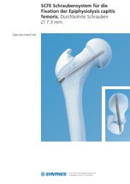
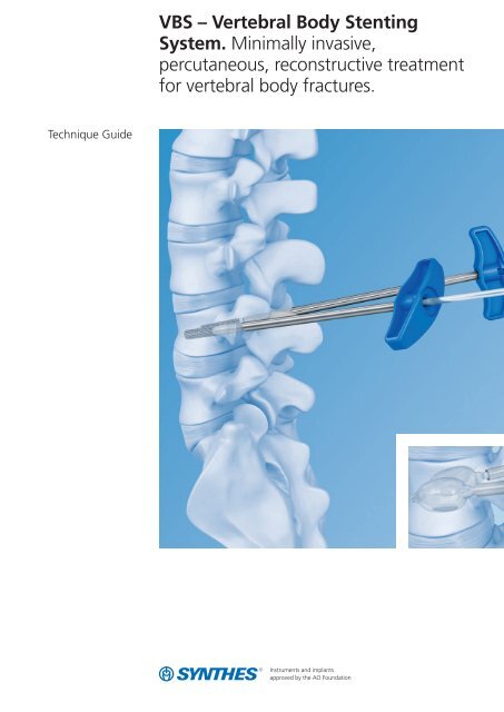
Technique Guide<br />
<strong>VBS</strong> <strong>–</strong> <strong>Vertebral</strong> <strong>Body</strong> <strong>Stenting</strong><br />
<strong>System</strong>. <strong>Minimally</strong> <strong>invasive</strong>,<br />
percutaneous, reconstructive treatment<br />
for vertebral body fractures.
Image intensifier control<br />
Warning<br />
This description alone does not provide sufficient background for direct use of<br />
the instrument set. Instruction by a surgeon experienced in handling these<br />
instruments and the attendance of a <strong>VBS</strong> training in order to know the <strong>VBS</strong><br />
instrumentation and technique is highly recommended.<br />
Reprocessing, Care and Maintenance of<br />
<strong>Synthes</strong> Instruments<br />
For general guidelines, function control and dismantling of multi-part instruments,<br />
please refer to: www.synthes.com/reprocessing
Table of Contents<br />
Introduction<br />
<strong>VBS</strong> <strong>Vertebral</strong> <strong>Body</strong> <strong>Stenting</strong> <strong>System</strong> 2<br />
AO Principles 4<br />
Indications and Contraindications 5<br />
Surgical Technique<br />
Preoperative Planning 7<br />
Preparation 8<br />
Patient Positioning 11<br />
Access Options 12<br />
Instrument Positioning 13<br />
A With Guide Wires<br />
<strong>–</strong> A1 Transpedicular Access 14<br />
<strong>–</strong> A2 Extra-/Parapedicular Access 17<br />
B With Trocars<br />
<strong>–</strong> B1 Transpedicular Access 21<br />
<strong>–</strong> B2 Extra-/Parapedicular Access 22<br />
Create Access Channel 23<br />
Determine Stent Size 24<br />
Optional: Use of VBB 25<br />
Inflation of VBB 30<br />
Using the <strong>VBS</strong> Catheter 34<br />
Deployment of Stents 38<br />
Cement Augmentation 42<br />
Product Information<br />
Implants and Balloon-Catheters 44<br />
Instruments 46<br />
Bibliography 48<br />
<strong>VBS</strong> Technique Guide <strong>Synthes</strong> 1
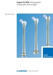
<strong>VBS</strong> <strong>–</strong> <strong>Vertebral</strong> <strong>Body</strong> <strong>Stenting</strong><br />
<strong>System</strong>. <strong>Minimally</strong> <strong>invasive</strong>,<br />
percutaneous, reconstructive treatment<br />
for vertebral body fractures.<br />
<strong>VBS</strong> is a safe treatment method for<br />
painful vertebral body fractures and<br />
lesions. It helps to prevent effects<br />
such as postural damage and pain<br />
caused by postural kyphosis.<br />
<strong>VBS</strong> offers unique benefits to<br />
patients and physicians:<br />
Percutaneous<br />
The <strong>VBS</strong> stents are introduced percutaneously<br />
into the vertebral body with<br />
only a stab incision required to place<br />
the access instruments.<br />
Reconstructive<br />
The <strong>VBS</strong> system restores the loss of<br />
height in the fractured vertebral body.<br />
Height conserving<br />
Expanding the <strong>VBS</strong> stents inside the<br />
collapsed vertebra offers height<br />
restoration and conservation. The<br />
mechanical construct restores the<br />
height while at the same time offering<br />
a cavity for injection of highly viscous<br />
PMMA based bone cement cleared for<br />
use in vertebro plasty or kyphoplasty<br />
procedures.<br />
<strong>Minimally</strong> <strong>invasive</strong>, percutaneous<br />
insertion of the <strong>Vertebral</strong> <strong>Body</strong><br />
<strong>Stenting</strong> <strong>System</strong><br />
Instrument insertion through a stab<br />
incision allows performing the procedure<br />
under either local or general<br />
anaesthesia.<br />
<strong>Vertebral</strong> <strong>Body</strong> Balloon (VBB)<br />
Simulate stent expansion in the vertebral<br />
body prior to <strong>VBS</strong> insertion.<br />
2 <strong>Synthes</strong> <strong>VBS</strong> Technique Guide
Optional <strong>Vertebral</strong> <strong>Body</strong> Balloon<br />
pre-cavity creation<br />
Simulation of stent expansion via<br />
balloon trialing allows fracture/lesion<br />
mobility confirmation<br />
Restoration through balloon<br />
dilatation and stent expansion<br />
Simultaneous dilatation of the bilaterally<br />
positioned <strong>VBS</strong> Stents offers an<br />
in situ controlled and continuous<br />
expansion.<br />
Expansion ratio up to 400%<br />
The <strong>Vertebral</strong> <strong>Body</strong> <strong>Stenting</strong> technology<br />
offers an expansion ratio up to 400%<br />
for the reconstruction of collapsed vertebrae.<br />
Controlled balloon dilatation with<br />
the <strong>VBS</strong> Inflation <strong>System</strong><br />
The applied pressure and injected volume<br />
of the mixture of saline solution<br />
and contrast medium can constantly be<br />
monitored and controlled with the help<br />
of the phosphorescent display.<br />
Augmentation with Vertecem V+<br />
Vertecem V+ is a PMMA based bone<br />
cement for the treatment of vertebral<br />
compression fractures:<br />
<strong>–</strong> About 27 minutes of working time<br />
<strong>–</strong> Excellent X-ray visibility<br />
<strong>VBS</strong> Technique Guide <strong>Synthes</strong> 3
AO Principles<br />
In 1958, the AO formulated four basic principles, which have<br />
become the guidelines for internal fixation 1 . They are:<br />
<strong>–</strong> Anatomic reduction<br />
<strong>–</strong> Stable fixation<br />
<strong>–</strong> Preservation of blood supply<br />
<strong>–</strong> Early, active mobilization<br />
The fundamental aims of fracture treatment in the limbs<br />
and fusion of the spine are the same. But a specific goal of<br />
spine treatment is to restore as much function as possible<br />
to the injured neural elements. 1<br />
AO Principles as applied to the spine 2<br />
Preservation of blood supply<br />
The proper atraumatic technique enables minimal retraction<br />
or disturbance of the nerve roots and dura, and maintains<br />
the stability of the facet joints. The ideal surgical technique<br />
and implant design minimize damage to anatomical structures,<br />
i.e. facet capsules and soft tissue attachment remain<br />
intact, and create a physiological environment that facilitates<br />
healing.<br />
Early, active mobilization<br />
The ability to restore normal spinal anatomy may permit the<br />
immediate reduction of pain, resulting in a more active, functional<br />
patient. The reduction in pain and improved function<br />
can result when a stable spine is achieved.<br />
Anatomic reduction<br />
Restoration of normal spine alignment improves the biomechanics<br />
of the spine and reduces pain by reestablishing and<br />
maintaining the natural curvature and the protective function<br />
of the spine.<br />
Stable fixation<br />
In the spine, the goal of internal fixation is to maintain not<br />
only the integrity of a mobile segment, but also to maintain<br />
the balance and the physiologic three-dimensional form<br />
of the spine. A stable spinal segment allows bony fusion at<br />
the junction of the lamina and pedicle.<br />
1<br />
Müller ME, Allgöwer M, Schneider R, Willenegger H (1995) Manual of Internal<br />
Fixation. 3rd, exp. a. completely revised ed. 1991. Berlin, Heidelberg, New York:<br />
Springer<br />
2<br />
Aebi M, Arlet V, Webb JK (2007) AOSPINE Manual (2 vols), Stuttgart, New York:<br />
Thieme<br />
4 <strong>Synthes</strong> <strong>VBS</strong> Technique Guide
Indications and Contraindications<br />
Intended use<br />
The <strong>VBS</strong> <strong>System</strong> is intended for the reduction of painful<br />
vertebral compression fractures and/or creation of a void in<br />
cancellous bone in the spine for the treatment of levels<br />
ranging from Th5-L5. It is intended to be used in combination<br />
with a legally-marketed PMMA 1 based bone cement<br />
adequately indicated for use in vertebroplasty or kyphoplasty<br />
procedures.<br />
Note: Refer to the manufacturer’s directions accompanying<br />
the bone cement for specific information on its use, precautions<br />
and warnings.<br />
Indications<br />
<strong>–</strong> Painful osteoporotic vertebral compression fractures without<br />
posterior wall involvement. Classified after Genant,<br />
Grade 2 and Grade 3.<br />
<strong>–</strong> Painful vertebral compression fractures classified after the<br />
AO classification:<br />
A1.1 Endplate impaction<br />
A1.2 Wedge impaction fracture<br />
A1.3 <strong>Vertebral</strong> body collapse<br />
A3.1 Incomplete burst fracture; matter of discretion<br />
(depending on the degree of posterior wall involvement,<br />
internal fixation must be used in addition)<br />
In combination with internal fixation:<br />
A3.1 Incomplete burst fracture<br />
A3.2 Burst-split fracture; matter of discretion (the extent<br />
of the gap width should not be too wide)<br />
B1.2 Posterior disruption predominantly ligamentous<br />
associated with type A fracture of the vertebral body<br />
B2.3 Posterior disruption predominantly osseous with<br />
type A fracture of the vertebral body<br />
<strong>–</strong> Palliative treatment of osteolytic lesions located within the<br />
vertebral body with intact cortical shell. Classified after<br />
Tomita Type 1.<br />
Contraindications<br />
<strong>–</strong> Lesions requiring open anterior column reconstruction<br />
<strong>–</strong> Acute or chronic systemic or localized spinal infections<br />
1<br />
Note: The long-term effects of PMMA based cements on the vertebral column are<br />
unknown. Therefore, the treating physician should weigh the benefits of the<br />
application of the PMMA based cement in younger patients against the potential<br />
risks.<br />
<strong>VBS</strong> Technique Guide <strong>Synthes</strong> 5
6 <strong>Synthes</strong> <strong>VBS</strong> Technique Guide
Preoperative Planning<br />
Patient assessment<br />
Requirements for assessing the indication:<br />
<strong>–</strong> Current X-ray images, if possible in standing position, of<br />
the thoracic and lumbar spine in two planes to assess the<br />
fracture and spinal alignment<br />
<strong>–</strong> A spiral CT and MRI scan (ideally with STIR frequency)<br />
of the painful region of the spine<br />
<strong>–</strong> If an MRI scan is contraindicated a bone scan may identify<br />
an acute fracture<br />
<strong>–</strong> Ruling out another cause of pain<br />
<strong>–</strong> Feasibility of surgery and use of anaesthesia<br />
<strong>–</strong> Ruling out impaired clotting<br />
Note: It is important, to treat only patients with nonconsolidated<br />
fractures.<br />
Warning: The patient should be checked for allergy to<br />
the contrast medium and stent material (CoCrWNi alloy).<br />
Planning of stent placement<br />
The placement of the stents should be planned based on the<br />
AP image which gives hints for the route of insertion.<br />
Pre-planning of stent size<br />
The stent size for the procedure can roughly be planned<br />
preoperatively via CT scan.<br />
Intraoperative X-ray imaging<br />
The <strong>Vertebral</strong> <strong>Body</strong> Stent must be implanted using X-ray on<br />
both planes, two C-arms, or with one freely mobile C-arm.<br />
<strong>VBS</strong> Technique Guide <strong>Synthes</strong> 7
Preparation<br />
Instrument preparation<br />
1<br />
Instrument Set<br />
03.804.512S<br />
<strong>Vertebral</strong> <strong>Body</strong> Stent Access Kit<br />
Instrument<br />
03.804.413S<br />
Inflation <strong>System</strong><br />
The inflation system has an angled manometer that shows<br />
the pressure in the balloon in pounds/inch 2 (psi) and atmospheres<br />
(atm). The volume scale on the fluid chamber measures<br />
milliliters (ml).<br />
It is necessary to prepare two inflation systems.<br />
1. Connect inflation system to connector<br />
Attach the tube of the inflation system with the Luer connector<br />
to the supplied 3-way connector as shown. Rotate the<br />
knob on the 3-way connector to position the “off” indicator<br />
towards the lateral outlet (1).<br />
2. Fill inflation system<br />
Fill the inflation system with saline solution and a liquid contrast<br />
medium.<br />
2<br />
White handle<br />
Note: It is essential to fill the inflation system with<br />
saline/contrast agent mixture to ensure better visibility of the<br />
<strong>VBS</strong> balloon catheter during inflation. The ratio of contrast<br />
medium to saline solution should be about 1:2.<br />
Plunger with red<br />
marking<br />
Prepare the contrast medium mixture in a cup and place the<br />
3-way connector under the solution. Push forward on the<br />
white wings on the inflation system and pull back on the<br />
handle until the plunger bottoms out. With the handle pointing<br />
upwards, tap the unit to clear the gauge portion of the<br />
inflation system of air (2).<br />
White wings<br />
8 <strong>Synthes</strong> <strong>VBS</strong> Technique Guide
Then hold the inflation system with the handle facing downward,<br />
and rotate the handle clockwise to expel all the air in<br />
the barrel until solution starts to emerge. Keep turning the<br />
handle clockwise until the leading edge of the red mark on<br />
the plunger reaches to approximately 3 to 4 ml under the<br />
zero marking or until the red marker on the plunger is<br />
aligned with the black line above the ml sign, underneath<br />
the zero marking (3).<br />
3<br />
The inflation system has now been prepared<br />
accordingly and can be set aside. Repeat for the second<br />
inflation system.<br />
Tip: The white wings may be pushed to unlock the plunger<br />
when large changes to the handle position are desired.<br />
The handle must be moved carefully to avoid overshooting<br />
the desired target.<br />
Warning: If the buttons (white wings) do not return to the<br />
locked position, do not force them as this could damage<br />
the plunger. Turn the handle gently, and the buttons (white<br />
wings) will return automatically to the locked position.<br />
<strong>VBS</strong> Technique Guide <strong>Synthes</strong> 9
Preparation<br />
Anatomical landmarks<br />
For vertebral body augmentation with <strong>VBS</strong>, the two stents<br />
per vertebra should be placed in a symmetrical, paramedian<br />
position within the affected vertebral body to achieve optimum<br />
reduction of the spinal fracture without damaging the<br />
lateral vertebral body edges. Ideally, the distance from the<br />
compressed endplate to the stents should be about 5 mm (1).<br />
The position of the stents needs to be planned based in preoperative<br />
imaging. Take care to achieve the planned position<br />
by determining the landmarks accordingly.<br />
The following landmarks have to be defined on the spine:<br />
<strong>–</strong> Both pedicles<br />
<strong>–</strong> Spinous process<br />
<strong>–</strong> Endplates<br />
<strong>–</strong> Posterior wall of vertebral body<br />
1<br />
~5 mm<br />
10 <strong>Synthes</strong> <strong>VBS</strong> Technique Guide
Patient Positioning<br />
Place the patient in the prone position on a lumbar support.<br />
The table must be radiolucent in both planes.<br />
The OR table should allow free manipulation of the C-arm<br />
over the operative site in both planes.<br />
<strong>VBS</strong> Technique Guide <strong>Synthes</strong> 11
Access Options<br />
There are two access options to the targeted vertebral body,<br />
depending on its anatomy:<br />
1<br />
1. Transpedicular access<br />
As a general rule, the bilateral skin incisions for the<br />
transpedicular approach are 1<strong>–</strong>2 cm lateral and up to 1 cm<br />
cranial to the centre of the pedicle (1).<br />
2. Extra-/Parapedicular access<br />
The bilateral skin incisions for the extra-/parapedicular technique<br />
are planned according to the anatomical situation (2).<br />
2<br />
The instruments for inserting the <strong>VBS</strong> system can be placed<br />
using either a guide wire or a trocar. In the chapter<br />
“Instrument Positioning” each procedure is explained for<br />
a transpedicular and an extra-/parapedicular access.<br />
For positioning instruments with guide wires see page 13.<br />
For positioning instruments with trocar see page 20.<br />
12 <strong>Synthes</strong> <strong>VBS</strong> Technique Guide
Instrument Positioning<br />
A With Guide Wires<br />
Instrument Set<br />
03.804.512S<br />
<strong>Vertebral</strong> <strong>Body</strong> Stent Access Kit<br />
1<br />
First the guide wires are positioned. The other instrumentation<br />
follows the path created by the guide wires.<br />
Once the anatomical landmarks are detected, the guide<br />
wires can be percutaneously introduced through skin incisions<br />
using X-ray control (AP and lateral).<br />
5 mm<br />
Either a transpedicular or extra-/parapedicular access may be<br />
selected depending on the anatomy of the vertebral body to<br />
be treated.<br />
Note: With either access technique it is important to plan to<br />
place the two stents symmetrically towards the midline and<br />
the anterior wall of the vertebral body at a medial location.<br />
In this position the stents have room to expand without<br />
pressing against either the lateral wall, or the other stent (1).<br />
<strong>VBS</strong> Technique Guide <strong>Synthes</strong> 13
A1 Transpedicular Access<br />
1<br />
Position guide wires<br />
Make the skin incisions.<br />
Under AP and lateral X-ray control insert the guide wires to<br />
the superior outer pedicle quadrant using slight manual pressure.<br />
Once the guide wires touch bone the outlines of the lateral<br />
pedicle are reached. Drive both guide wires with controlled<br />
blows from a hammer through the cortex. Cautiously advance<br />
the guide wires into the center of the vertebral body.<br />
Note: The tips of the guide wires should be about and not<br />
closer than 5 mm to the anterior wall of the vertebral body.<br />
They should be positioned symmetrically and aligned in both<br />
AP and lateral views. Confirm this placement for the positioning<br />
of the stents.<br />
Warning: The tips of the guide wires must not pass the midline<br />
in AP view until they have passed the posterior wall in<br />
the lateral view. When advancing the guide wires, ensure<br />
that they are not inserted too far medially, to avoid penetration<br />
into the spinal canal. It is also essential to avoid over -<br />
driving the guide wires into vascular structures beyond the<br />
anterior cortical wall.<br />
14 <strong>Synthes</strong> <strong>VBS</strong> Technique Guide
2<br />
Position working sleeves over guide wires<br />
1<br />
Take the instrument assembly of working sleeve, side-opening<br />
cannula and cannulated trocar (1). Push the instrument<br />
assembly with a counterclockwise turning motion over the<br />
first guide wire (2).<br />
Warning: Do not insert the working sleeve into the bone<br />
without the side-opening cannula. This could damage the<br />
working sleeve and obstruct stent insertion. Do not hammer<br />
on the side-opening cannula, cannulated trocar and working<br />
sleeve.<br />
The working sleeve can also be placed without the mounted<br />
cannulated trocar (working sleeve with side-opening cannula<br />
over guide wire). If this method is chosen, there is more<br />
clearance between the diameter of the guide wire and the<br />
side-opening cannula to allow for minor correction in the<br />
trajectory when positioning the working sleeve. This can lead<br />
to a slight resistance when penetrating the bony vertebral<br />
body surface.<br />
2<br />
<strong>VBS</strong> Technique Guide <strong>Synthes</strong> 15
A1 Transpedicular Access<br />
Monitor working sleeve placement under lateral X-ray control.<br />
Ensure that the tip of the working sleeve has passed the<br />
pedicle and is positioned inside the vertebral body.<br />
4<br />
Note: When inserting the working sleeve, carefully monitor<br />
the position of the guide wire to confirm that it is not advancing<br />
forward.<br />
Tip: Pull back the side-opening cannula to verify the<br />
positioning of the working sleeve.<br />
Repeat on the contra-lateral side (4).<br />
Once both working sleeves are in place, remove the sideopening<br />
cannulae with the inserted cannulated trocar and<br />
the guide wires (5).<br />
The working sleeves remain in the vertebral body.<br />
5<br />
Warning: It is important to advance the instrument assembly<br />
carefully in order to avoid any injury to the physician’s<br />
hand. Since the guide wire is longer than the combined<br />
length of the pre-mounted working sleeve with the sideopening<br />
cannula with cannulated trocar, it will protrude<br />
through the handle of the side-opening cannula (6).<br />
6<br />
16 <strong>Synthes</strong> <strong>VBS</strong> Technique Guide
A2 Extra-/Parapedicular Access<br />
1<br />
Position guide wires<br />
Make the skin incisions.<br />
Under AP and lateral X-ray control, insert the guide wires<br />
using slight manual pressure.<br />
Insert both guide wires up to the vertebral body and drive<br />
them with controlled blows from a hammer through the<br />
cortex. Should you touch bone before reaching the vertebral<br />
body you have reached the outline of the lateral pedicle.<br />
Note: Cautiously advance the guide wires and, if necessary,<br />
redirect in order to reach the center of the vertebral body.<br />
The tips of the guide wires should be about and not closer<br />
than 5 mm to the anterior wall of the vertebral body.<br />
Warning: The tips of the guide wires must not pass the midline<br />
in AP view until they have passed the posterior wall in<br />
the lateral view. When advancing the guide wires, ensure<br />
that they are not inserted too far medially, to avoid pene -<br />
tration into the spinal canal. It is also essential to avoid overdriving<br />
the guide wires into vascular structures beyond the<br />
anterior cortical wall.<br />
<strong>VBS</strong> Technique Guide <strong>Synthes</strong> 17
A2 Extra-/Parapedicular Access<br />
2<br />
Positioning working sleeves over guide wires<br />
1<br />
Take the instrument assembly of working sleeve, side-opening<br />
cannula and cannulated trocar (1). Push the instrument<br />
assembly with a counterclockwise turning motion over the<br />
first guide wire (2).<br />
Warning: Do not insert the working sleeve into the bone<br />
without the side-opening cannula. This could damage the<br />
working sleeve and obstruct stent insertion. Do not hammer<br />
on the side-opening cannula, cannulated trocar and working<br />
sleeve.<br />
The working sleeve can also be placed without the mounted<br />
cannulated trocar (working sleeve with side-opening cannula<br />
over guide wire). Then, there is more clearance between the<br />
diameter of the guide wire and the side-opening cannula to<br />
allow for minor correction in the trajectory when positioning<br />
the working sleeve. This can lead to a slight resistance when<br />
penetrating the bony vertebral body surface (3).<br />
2<br />
3<br />
18 <strong>Synthes</strong> <strong>VBS</strong> Technique Guide
Monitor working sleeve placement under lateral X-ray control.<br />
Advance the tip of the working sleeve until it has penetrated<br />
the cortex and is tightly seated into the bone.<br />
4<br />
Note: When inserting the working sleeve, carefully monitor<br />
the position of the guide wire to confirm that it is not advancing<br />
forward.<br />
Tip: Pull back the side-opening cannula to verify the<br />
positioning of the working sleeve.<br />
Repeat on the contra-lateral side (4).<br />
Once both working sleeves are in place, remove the sideopening<br />
cannulae with the inserted cannulated trocar and<br />
the guide wires (5).<br />
The working sleeves remain in the vertebral body.<br />
5<br />
Warning: It is important to advance the instrument assembly<br />
carefully in order to avoid any injury to the physician’s<br />
hand. The guide wire is longer than the combined length of<br />
the instrument assembly of working sleeve and the sideopening<br />
cannula and cannulated trocar will protrude<br />
through the handle of the side-opening cannula (6).<br />
6<br />
<strong>VBS</strong> Technique Guide <strong>Synthes</strong> 19
Instrument Positioning<br />
B With Trocars<br />
Instrument Set<br />
03.804.512S<br />
<strong>Vertebral</strong> <strong>Body</strong> Stent Access Kit<br />
When using trocars for instrument positioning, creating the<br />
pathway and positioning of the instrumentation is achieved<br />
in one step.<br />
Either a transpedicular or extra-/parapedicular access may be<br />
selected depending on the anatomy of the vertebral body<br />
to be treated.<br />
Note: With either access technique it is important to plan to<br />
place the two stents symmetrically towards the midline.<br />
20 <strong>Synthes</strong> <strong>VBS</strong> Technique Guide
B1 Transpedicular Access<br />
Positioning working sleeves<br />
Make skin incisions.<br />
1<br />
Take the instrument assembly of working sleeve, side-opening<br />
cannula and cannulated trocar. Replace the cannulated<br />
trocar by the trocar and lock it into place with a clockwise<br />
rotation (1).<br />
Under AP and lateral X-ray control insert the instrument assembly<br />
through the skin incision to the superior outer pedicle<br />
quadrant using slight manual pressure and a counterclockwise<br />
turning motion (2). If necessary the instrument assembly<br />
can be inserted through the cortex with light impaction on<br />
the metal end of the trocar using a hammer.<br />
Tip: Pull back the side-opening cannula to verify the<br />
positioning of the working sleeve.<br />
2<br />
Warning: When advancing the instrument assembly, ensure<br />
that the trocar tip is not inserted too far medially, to avoid<br />
penetration into the spinal canal. It is also essential to avoid<br />
overdriving the trocar tip into vascular structures beyond the<br />
anterior cortical wall.<br />
Hold the working sleeve in place and carefully rotate and remove<br />
the trocar and the side-opening cannula. The working<br />
sleeve remains in the vertebral body.<br />
Repeat for the contra-lateral side (3).<br />
Warning: Do not insert the working sleeve into the bone<br />
without the side-opening cannula and trocar. This could<br />
damage the working sleeve and obstruct stent insertion.<br />
3<br />
Do not redirect the instrument assembly without removing it<br />
and re-accessing the pedicle.<br />
<strong>VBS</strong> Technique Guide <strong>Synthes</strong> 21
B2 Extra-/Parapedicular Access<br />
Positioning working sleeves<br />
Make skin incisions.<br />
1<br />
Take the instrument assembly of working sleeve, side-opening<br />
cannula and cannulated trocar. Replace the cannulated<br />
trocar by the trocar and lock it into place with a clockwise<br />
rotation (1).<br />
Under AP and lateral X-ray control insert the instrument assembly<br />
through the skin incision into the vertebral body<br />
using slight manual pressure and a counterclockwise turning<br />
motion (2). If necessary the instrument assembly can be inserted<br />
through the cortex with light impaction on the metal<br />
end of the trocar using a hammer.<br />
Advance the instrument assembly so that the opening of the<br />
working sleeve is anterior to the posterior wall of the vertebral<br />
body.<br />
2<br />
Tip: Pull back the side-opening cannula to verify the<br />
positioning of the working sleeve.<br />
Warning: When advancing the instrument assembly, ensure<br />
that the trocar tip is not inserted too far medially, to avoid<br />
penetration into the spinal canal. It is also essential to avoid<br />
overdriving the trocar tip into vascular structures beyond the<br />
anterior cortical wall.<br />
Hold the working sleeve in place and carefully rotate and remove<br />
the trocar and the side-opening cannula. The working<br />
sleeve remains in the vertebral body.<br />
3<br />
Repeat for the contra-lateral side (3).<br />
Warning: Do not insert the working sleeve into the bone<br />
without the side-opening cannula and trocar. This could<br />
damage the working sleeve and obstruct stent insertion. Do<br />
not redirect the instrument assembly without removing it<br />
and re-accessing the bone.<br />
22 <strong>Synthes</strong> <strong>VBS</strong> Technique Guide
Create Access Channel<br />
Instrument Set<br />
03.804.512S<br />
<strong>Vertebral</strong> <strong>Body</strong> Stent Access Kit<br />
1<br />
Guide the drill (1) and afterwards the blunt plunger (2)<br />
through the working sleeves to create an access channel for<br />
the stents.<br />
Warning: Use lateral X-ray intensification to avoid penetrating<br />
the anterior cortex of the vertebral body. It is essential to<br />
avoid overdriving these instruments into vascular structures<br />
beyond the anterior cortical wall.<br />
Warning: Do not use a hammer to drive the drill forward.<br />
The drill may aggressively advance with rotation.<br />
The plunger can be driven forward with light hammer blows.<br />
Ensure that the hammer blows hit the protruding metal pin<br />
and not the plastic handle (2).<br />
Warning: While using drill or plunger, it is important to ensure<br />
that the working sleeves do not move. Do not use<br />
the drill or plunger to manipulate or correct the direction of<br />
the working sleeve.<br />
2<br />
Repeat on the contra-lateral side.<br />
<strong>VBS</strong> Technique Guide <strong>Synthes</strong> 23
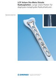
Determine Length of Stent<br />
The <strong>Vertebral</strong> <strong>Body</strong> Stents and Balloons are available in three<br />
sizes:<br />
1<br />
<strong>Vertebral</strong> <strong>Body</strong> Stent/Balloon<br />
Article No. Max Stent Stent length Release<br />
expanded expanded length<br />
(VBB/<strong>VBS</strong>)<br />
09.804.500S 15 mm 13 mm 22 mm<br />
09.804.600S<br />
Small<br />
09.804.501S 17 mm 15 mm 27 mm<br />
09.804.601S<br />
Medium<br />
09.804.502S 17 mm 20 mm 31 mm<br />
09.804.602S<br />
Large<br />
The plunger has three grooves towards the distal tip that<br />
correspond to the three stent lengths (1).<br />
Use lateral imaging to select the length of the stent on the<br />
basis of these grooves.<br />
From distal tip the first groove visible:<br />
<strong>Vertebral</strong> <strong>Body</strong> Stent Small<br />
From distal tip the second groove visible:<br />
<strong>Vertebral</strong> <strong>Body</strong> Stent Medium<br />
From distal tip the third groove visible:<br />
<strong>Vertebral</strong> <strong>Body</strong> Stent Large<br />
Establish the stent size on both sides, they may differ.<br />
Stent<br />
length<br />
Release<br />
length<br />
24 <strong>Synthes</strong> <strong>VBS</strong> Technique Guide
Optional: Use of VBB<br />
If you do not intend to use the VBB please continue to<br />
page 34 chapter “Using the <strong>VBS</strong>”.<br />
The <strong>VBS</strong> <strong>System</strong> can optionally be used with a <strong>Vertebral</strong> <strong>Body</strong><br />
Balloon (VBB). The VBB allows simulating the stent expansion<br />
when bone quality, age of the fracture or the fracture / lesion<br />
mobility of the vertebral body is unknown.<br />
1<br />
Unpacking the VBB Catheter<br />
Remove the VBB catheter from the sterile packaging (1).<br />
1 2<br />
Stiffening wire<br />
White cover<br />
sleeve<br />
Note: Slide back the white cover sleeve towards the Luer<br />
connector and attach it properly to the luer (2). This cover<br />
sleeve can be used later for stretching and folding back the<br />
VBB after catheter removal for reuse.<br />
Do not remove the stiffening wire from the VBB catheter.<br />
The stiffening wire will be removed and the creation of the<br />
vacuum will be performed after the insertion of the VBB<br />
catheter on the patient. This is different compared to the<br />
<strong>VBS</strong> catheter insertion.<br />
There is a white marking range on the balloon catheter shaft<br />
indicating release length, i.e. the overall length and both<br />
proximal and distal balloon shoulders segments when the<br />
white marking range is completely inserted into the working<br />
sleeve.<br />
The VBB can be reused once within one surgery.<br />
VB Balloon<br />
Warning: Only use the VBB of same size together with the<br />
corresponding <strong>VBS</strong>.<br />
Note: The shaft marker indicates when balloon is fully<br />
inserted, use X-ray while inflating with contrast media.<br />
<strong>VBS</strong> Technique Guide <strong>Synthes</strong> 25
Optional: Use of VBB<br />
2<br />
Insertion of the VBB<br />
1<br />
Insert the VBB catheter under lateral X-ray control.<br />
Note: The full release (initial) length of the VBB is outside<br />
when the proximal end of the white marking of the catheter<br />
shaft disappears into the working sleeve.<br />
Check the position under X-ray control and confirm the desired<br />
position under AP view (1). It is important, that the<br />
whole balloon portion is positioned completely inside the<br />
vertebra and that these inflatable segments have completely<br />
passed through the working sleeve. Make sure to position<br />
the VBB according to the anticipated <strong>VBS</strong> position.<br />
Repeat for the contra-lateral side.<br />
Note: Simultaneous dilatation of bilateral inserted VBBs is<br />
recommended for optimal performance.<br />
Note: Make sure to position the VBB according to the anticipated<br />
<strong>VBS</strong> position.<br />
26 <strong>Synthes</strong> <strong>VBS</strong> Technique Guide
3<br />
Connecting VBB catheter to inflation system<br />
and create vacuum<br />
1<br />
Instrument<br />
03.804.413S<br />
Inflation <strong>System</strong><br />
Remove stiffening wire prior to connecting the VBB to the inflation<br />
system and keep it.<br />
J<br />
Note: Stiffening wire will be used for balloon refolding (in<br />
conjunction with the cover sleeve) and reinsertion.<br />
K<br />
Connect the prepared inflation systems with the selected<br />
VBB catheters using the Luer connector (1).<br />
Note: It is important to ensure that all Luer connectors are<br />
securely attached. Loose connections may result in inaccurate<br />
filling volumes and pressures.<br />
Push the white wings on the inflation system forward to unlock<br />
the handle. Pull the handle all the way back, and release<br />
the wings to lock the handle in position. This pulls air<br />
out of the catheter, creating a vacuum inside it. The vacuum<br />
can be monitored on the display “vac” (2).<br />
2<br />
Warning: If the buttons (white wings) do not return to the<br />
locked position, do not force them as this could damage<br />
the plunger. Turn the handle gently, and the buttons (white<br />
wings) will return automatically to the locked position.<br />
<strong>VBS</strong> Technique Guide <strong>Synthes</strong> 27
Optional: Use of VBB<br />
Close the balloon catheter with the 3-way connector by positioning<br />
the “off” indicator towards the catheter. This retains<br />
the vacuum inside the catheter (3).<br />
3<br />
Hold the inflation system with the handle facing downward<br />
and turn the handle clockwise in order to set the volume<br />
scale to zero. This is done by turning the handle until the red<br />
ring on the plunger is precisely at “0” (4).<br />
4<br />
28 <strong>Synthes</strong> <strong>VBS</strong> Technique Guide
This flushes out the excess saline solution/contrast medium<br />
mixture and air through the lateral opening of the three-way<br />
connector (5).<br />
5<br />
Tip: Suspend the 3-way connector over a receptacle for all<br />
steps that involve expelling excess solution. If vacuuming<br />
on the patient, use absorbent cotton to soak up any expelled<br />
excess solution.<br />
Rotate the knob on the 3-way connector to position the<br />
“off”indicator towards the lateral side opening. This allows<br />
flow from the Inflation system into the VBB balloon<br />
catheter (6).<br />
6<br />
<strong>VBS</strong> Technique Guide <strong>Synthes</strong> 29
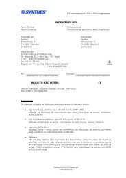
Inflation of VBB<br />
1<br />
Inflation of VBB<br />
2<br />
Note: Simultaneous dilatation of bilateral devices is recommended<br />
for optimal performance.<br />
Warning: It is essential to use AP and lateral X-rays to track<br />
VBB expansion via the balloon contrast media solution inflation<br />
fluid.<br />
Slowly increase pressure and volume by rotating the handles<br />
of the connected inflation systems in a clockwise direction<br />
on both sides.<br />
Proceed slowly after each VBB balloon unfolds and starts<br />
expanding at approx. 12 atm (2). Match the expansion bi -<br />
laterally by tracking the fluid volume on the syringe body<br />
with the black volume markers positioned in ml increments.<br />
When the pressure reaches and increases beyond 26 atm,<br />
continue dilatation gradually. Wait a few seconds then slowly<br />
continue until the desired VBB diameter is reached (3). The<br />
maximum stent diameter is 15 mm for VBB Small and 17<br />
mm for both VBB Medium and VBB Large.<br />
Stop balloon expansion when any of the following happens:<br />
1. Desired vertebral body height or angle is reached<br />
2. Pressure reaches 30 atm (400 PSI)<br />
3. VBB volume reaches maximum<br />
<strong>–</strong> 4.0 ml for VBB Small<br />
<strong>–</strong> 4.5 ml for VBB Medium<br />
<strong>–</strong> 5.0 ml for VBB Large<br />
Note: The VBB expansion pressure and volume on the inflation<br />
system have to be monitored carefully on the inflation<br />
system’s phosphorescent manometer (units: bar/atm, PSI)<br />
and syringe body with black volume markers (units: ml/cc),<br />
respectively.<br />
30 <strong>Synthes</strong> <strong>VBS</strong> Technique Guide
Warning: Do not fill the balloons over their maximum volume<br />
or pressure. If this is done, they may leak.<br />
Warning: VBB maximum volumes differ from <strong>VBS</strong> maximum<br />
volumes!<br />
Note: In case of contrast medium leakage, pull vacuum, insert<br />
stiffening wire and remove balloon, don't reuse balloon.<br />
2<br />
Retrieve balloon catheters<br />
1<br />
Slowly turn the handles of the inflation systems counterclockwise<br />
to draw the liquid out of the balloon catheter (1).<br />
Once the pressure has reached 10 atm, push the white wings<br />
forward, slowly pull the handle back all the way, and release<br />
the white wings (2). This draws and holds a vacuum in the<br />
catheter.<br />
2<br />
<strong>VBS</strong> Technique Guide <strong>Synthes</strong> 31
Inflation of VBB<br />
Aerate the VBB catheter by first positioning the “off” indicator<br />
towards the catheter (1) and second turn back towards<br />
the lateral side opening (1 inset).<br />
1<br />
Disconnect the inflation system from the VBB catheter.<br />
Note: Carefully insert the stiffening wire into the VBB<br />
catheter under X-ray control.<br />
Apply a gentle force in order to stretch the deflated balloon<br />
prior to removal of the catheter (2). Make sure not to damage<br />
the VBB catheter by pushing too hard.<br />
Hold the working sleeves in place and pull carefully on the<br />
catheters to retrieve the balloons. Rotate the catheters if<br />
needed to ease balloon removal.<br />
Note: The VBB catheter can be re-used once within one surgery.<br />
Make sure by visual inspection that the VBB catheter<br />
has not been damaged.<br />
Warning: do not use a VBB catheter when a visual damage<br />
is observed, or when a leak is evident.<br />
Warning: If balloon-catheter material is remaining in vertebral<br />
body after removal of the VBB do not leave it implanted.<br />
The balloon-catheter material is not implant grade material.<br />
2<br />
32 <strong>Synthes</strong> <strong>VBS</strong> Technique Guide
Note: If the VBB catheter is planned to be reused within the<br />
same surgery, cover the re-folded balloon of the VBB<br />
catheter with the white cover sleeve (3) and reinsert stiffening<br />
wire to gently straighten the balloon.<br />
3<br />
<strong>VBS</strong> Technique Guide <strong>Synthes</strong> 33
Using the <strong>VBS</strong> Catheter<br />
Note: the fracture must be mobile in order height restoration<br />
is possible. In order to simulate stent expansion use optional<br />
VBB (s. page 25)<br />
Stiffening wire<br />
1<br />
Unpacking the <strong>VBS</strong> Catheters<br />
Remove the <strong>VBS</strong> catheter from the sterile packaging. Carefully<br />
remove the stiffening wire and put it aside for possible<br />
further use.<br />
If preferred, the stiffening wire can also be removed after the<br />
insertion of the balloon catheter. If this method is chosen,<br />
the creation of the vacuum has to be performed after the insertion<br />
of the balloon catheter on the patient.<br />
There is a white marking range on the balloon catheter shaft<br />
indicating the release length, i.e. the overall length including<br />
the stent and both proximal and distal balloon shoulders segments,<br />
when the white marking range is completely inserted<br />
into the working sleeve.<br />
VB Stent<br />
34 <strong>Synthes</strong> <strong>VBS</strong> Technique Guide
2<br />
Connecting <strong>VBS</strong> catheter to inflation system and create<br />
vacuum<br />
1<br />
Instrument<br />
03.804.413S<br />
Inflation <strong>System</strong><br />
Connect the prepared inflation system with the selected <strong>VBS</strong><br />
balloon-catheters using the Luer connector (1).<br />
J<br />
Note: It is important to ensure that all Luer connectors are<br />
securely attached. Loose connections may result in inaccurate<br />
filling volumes and pressures.<br />
K<br />
Push the white wings on the inflation system forward to unlock<br />
the handle. Pull the handle all the way back, and release<br />
the wings to lock the handle in position. This pulls air<br />
out of the catheter, creating a vacuum inside it. The vacuum<br />
can be monitored on the display “vac” (2).<br />
Warning: If the buttons (white wings) do not return to the<br />
locked position, do not force them as this could damage the<br />
plunger. Turn the handle gently, and the buttons (white<br />
wings) will return automatically to the locked position.<br />
2<br />
<strong>VBS</strong> Technique Guide <strong>Synthes</strong> 35
Using the <strong>VBS</strong> Catheter<br />
Close the balloon catheter with the 3-way connector by positioning<br />
the “off” indicator towards the catheter. This retains<br />
the vacuum inside the catheter (3).<br />
3<br />
Hold the inflation system with the handle facing downward<br />
and turn the handle clockwise in order to set the volume<br />
scale to zero. This is done by turning the handle until the red<br />
ring on the plunger is precisely at “0” (4).<br />
4<br />
36 <strong>Synthes</strong> <strong>VBS</strong> Technique Guide
This flushes out the excess saline solution/contrast medium<br />
mixture and air through the lateral opening of the three-way<br />
connector (5).<br />
5<br />
Tip: Suspend the 3-way connector over a receptacle for all<br />
steps that involve expelling excess solution. If vaccuuming on<br />
the patient, use absorbent cotton to soak up any expelled<br />
excess solution.<br />
Rotate the knob on the 3<strong>–</strong>way connector to position the “off”<br />
indicator towards the lateral side opening. This allows flow<br />
from the inflation system into the <strong>VBS</strong> balloon catheter (6).<br />
6<br />
<strong>VBS</strong> Technique Guide <strong>Synthes</strong> 37
Deployment of Stents<br />
1<br />
Insert and deploy stents<br />
Insert the balloon catheter with the attached stent under<br />
lateral X-ray control. The full release (initial) length of the balloon<br />
with stent is outside the working sleeve when the proximal<br />
end of the white marking of the catheter shaft disappears<br />
into the working sleeve. Check the position under<br />
X-ray control and confirm the desired position under AP<br />
view (1). It is important, that the whole balloon portion including<br />
the stent is positioned completely inside the vertebra<br />
and that these parts have completely passed through the<br />
working sleeve.<br />
1<br />
Repeat on the contra-lateral side.<br />
Note: Simultaneous dilatation of bilateral devices is essential<br />
for optimal device performance. Once stent expansion has<br />
begun the stent cannot be undeployed or repositioned.<br />
Warning: It is essential to use AP and lateral X-rays to track<br />
stent expansion and balloon shoulder inflation via the<br />
radiopacity due to the stent and the balloon contrast media<br />
solution inflation fluid, respectively.<br />
Slowly increase pressure and volume by rotating the handles<br />
of the connected inflation system in a clockwise direction on<br />
both sides.<br />
38 <strong>Synthes</strong> <strong>VBS</strong> Technique Guide
Proceed slowly after the stents begin expanding at approx.<br />
12 atm (2). Match the expansion bilaterally by tracking the<br />
fluid volume on the scales. When the pressure reaches<br />
26 atm, continue dilatation gradually. Wait a few seconds<br />
then slowly continue until the desired stent diameter is<br />
reached (3). The maximum stent diameter is 15 mm for <strong>VBS</strong><br />
Small and 17 mm for both <strong>VBS</strong> Medium and <strong>VBS</strong> Large.<br />
2<br />
Stop balloon inflation when any of the following happens:<br />
1. Desired vertebral body height or angle is reached<br />
2. Pressure reaches 30 atm<br />
3. <strong>VBS</strong> volume reaches maximum<br />
<strong>–</strong> 4.5 ml for <strong>VBS</strong> Small<br />
<strong>–</strong> 5.0 ml for <strong>VBS</strong> Medium<br />
<strong>–</strong> 5.5 ml for <strong>VBS</strong> Large<br />
Note: The <strong>VBS</strong> expansion pressure and volume on the inflation<br />
<strong>System</strong> have to be monitored carefully on the inflation<br />
system’s phosphorescent manometer (units: bar/atm, PSI)<br />
and syringe body with black volume markers (units: ml/cc),<br />
respectively.<br />
Warning: Do not inflate the balloons beyond their maximum<br />
volume or pressure. If this is done, they may leak.<br />
Warning: <strong>VBS</strong> maximum volumes differ from VBB maximum<br />
volumes.<br />
3<br />
Once the expansion is stopped, record the volume of solution<br />
used indicated on the inflation system.<br />
<strong>VBS</strong> Technique Guide <strong>Synthes</strong> 39
Deployment of Stents<br />
2<br />
Retrieve balloon catheters<br />
1<br />
To maintain maximum stent expansion, gradually decrease<br />
the pressure simultaneously on both sides. Slowly turn the<br />
handles of the inflation system counter-clockwise to draw<br />
the liquid out of the balloon catheter (1). Once the pressure<br />
has reached 10 atm, push the white wings forward, slowly<br />
pull the handle back all the way, and release the white wings<br />
(2). This draws and holds a vacuum in the catheter and collapses<br />
the balloon for its removal.<br />
Hold the working sleeves in place and pull firmly on the<br />
catheters to retrieve the balloons. Rotate the catheters if<br />
needed to ease balloon on removal. The stents remain in the<br />
vertebral body.<br />
Verify the position of the bilaterally positioned stents under<br />
AP and lateral X-ray control.<br />
Tip: If the stent expansion is inadvertently asymmetric or if a<br />
balloon leaks, the intact balloon catheter from the contra-lateral<br />
side can be reinserted in the vertebral body on the ipsilateral<br />
side and be repositioned in the stent and can be<br />
reused for further expansion. In that case, disconnect the inflation<br />
system from the balloon catheter, carefully insert the<br />
stiffening wire and replace the balloon catheter through the<br />
working sleeve in the vertebral body. Carefully monitor the<br />
insertion under lateral X-ray control. Stop insertion when the<br />
top end of the white range on the catheter shaft is aligned<br />
with the top of the working sleeve. Check the position under<br />
X-ray control and confirm the desired position under AP view.<br />
Ensure that the stent does not move while switching the balloon-catheter.<br />
Remove the stiffening wire and reconnect the<br />
inflation system, repeat the steps of creating a vacuum and<br />
re-inflate the balloon as described in this section.<br />
2<br />
40 <strong>Synthes</strong> <strong>VBS</strong> Technique Guide
Note: If the contrast medium/saline solution mixture leaks<br />
when the stents are expanded, it may be more difficult to remove<br />
the balloon catheters through the working sleeves. If<br />
necessary remove the balloon catheters together with the<br />
working sleeves or insert the stiffening wire for removal.<br />
Warning: If balloon material is remaining in vertebral body<br />
after removal of the <strong>VBS</strong> balloon do not leave it implanted.<br />
The balloon material is not implant grade material.<br />
<strong>VBS</strong> Technique Guide <strong>Synthes</strong> 41
Cement Augmentation<br />
1<br />
Inject PMMA based bone cement<br />
Additional cement augmentation with a legally marketed<br />
PMMA based bone cement adequately indicated for use in<br />
vertebroplasty or kyphoplasty procedures is mandatory.<br />
1<br />
After cavity creation with VBB or <strong>VBS</strong>, inject PMMA based<br />
cement bilaterally.<br />
Insert the side-opening cannulae into the working sleeves.<br />
Connect the syringes. The volume of cement required can be<br />
estimated from the volume of balloon inflation fluid medium<br />
needed for VBB or <strong>VBS</strong> expansion (1).<br />
It is mandatory to monitor cement flow under real-time x-ray<br />
control.<br />
Warning: Cement should be injected until it infiltrates the<br />
surrounding cancellous bone around the cavity created by<br />
the balloon or the stent. For safer cement application, high<br />
viscosity cement should be used (2).<br />
Tip: The side-opening cement outflow window can be<br />
closed by turning the cannula.<br />
2<br />
It is recommended to use Vertecem V+.<br />
Vertecem V+ is a PMMA based bone cement to treat vertebral<br />
compression fractures:<br />
<strong>–</strong> About 27 minutes of working time<br />
<strong>–</strong> Excellent X-ray visibility<br />
Note: Refer to the manufacturer’s directions accompanying<br />
the bone cement for specific information on its use, pre-cautions<br />
and warnings.<br />
42 <strong>Synthes</strong> <strong>VBS</strong> Technique Guide
2<br />
Remove side-opening needles and working sleeves<br />
Wait until the cement has fully hardened. Observe the bone<br />
cement manufacturer’s instructions as the hardening times<br />
for PMMA based cements can greatly vary.<br />
Usually instruments used for the cement injection shall be removed<br />
after hardening of PMMA based bone cement by<br />
twisting the instrument assembly several times to sever the<br />
cement bridge.<br />
Suture the wound with tight stitches for hemostasis.<br />
Postoperative procedure<br />
To compress the wound the patient should be placed in a<br />
supine position for an hour after surgery. Bruising may occur<br />
at the puncture sites. The patient can then be mobilized at<br />
discretion.<br />
<strong>VBS</strong> Technique Guide <strong>Synthes</strong> 43
Implants and Balloon-Catheters<br />
<strong>Vertebral</strong> <strong>Body</strong> Stent<br />
09.804.500S 09.804.501S 09.804.502S<br />
<strong>VBS</strong> Small <strong>VBS</strong> Medium <strong>VBS</strong> Large<br />
Release 22 mm 27 mm 31 mm<br />
(initial)<br />
length<br />
Stent 13 mm 15 mm 20 mm<br />
length<br />
expanded<br />
Max 15 mm 17 mm 17 mm<br />
expanded<br />
Max 4.5 ml 5.0 ml 5.5 ml<br />
volume<br />
Max 30 bar 30 bar 30 bar<br />
pressure<br />
44 <strong>Synthes</strong> <strong>VBS</strong> Technique Guide
<strong>Vertebral</strong> <strong>Body</strong> Stent with Balloon<br />
The <strong>Vertebral</strong> <strong>Body</strong> Stent with Ballon consists out of a double<br />
pack containing one <strong>VBS</strong> and one corresponding VBB<br />
catheter.<br />
The respective sizes are Small, Medium and Large:<br />
09.804.600S 09.804.601S 09.804.602S<br />
<strong>VBS</strong> Small <strong>VBS</strong> Medium <strong>VBS</strong> Large<br />
with Balloon with Balloon with Balloon<br />
The dimensions of the <strong>VBS</strong> are as described on page 44 and<br />
the respective VBB are:<br />
Small Medium Large<br />
Balloon Balloon Balloon<br />
Release 22 mm 27 mm 31 mm<br />
(initial)<br />
Max 15 mm 17 mm 17 mm<br />
expanded<br />
Max 4.0 ml 4.5 ml 5.0 ml<br />
volume<br />
Max 30 bar 30 bar 30 bar<br />
pressure<br />
<strong>VBS</strong> Technique Guide <strong>Synthes</strong> 45
Instruments<br />
03.804.512S<br />
<strong>Vertebral</strong> <strong>Body</strong> Stent Access Kit<br />
Contents:<br />
2Cannulae with Side Opening,<br />
with Luer lock<br />
2Injection cannulae with Luer lock<br />
2Guide Wires, with Depth Markings<br />
2Trocar<br />
2Cannulated trocar<br />
2<strong>Vertebral</strong> <strong>Body</strong> Stent Access Working<br />
Sleeve<br />
1<strong>Vertebral</strong> <strong>Body</strong> Stent Access Drill<br />
1<strong>Vertebral</strong> <strong>Body</strong> Stent Access Plunger<br />
03.804.413S<br />
<strong>VBS</strong> Inflation <strong>System</strong><br />
46 <strong>Synthes</strong> <strong>VBS</strong> Technique Guide
Optional Instruments<br />
399.410 Hammer, 300 g<br />
292.210S Kirschner Wire 2.0 mm with trocar tip,<br />
length 280 mm, Stainless Steel, sterile<br />
Vertecem V+ <strong>System</strong><br />
07.702.016S<br />
Vertecem V+ Cement Kit<br />
Containing:<br />
1Vertecem V+ Mixer pre-filled with<br />
cement powder<br />
1Monomer glass ampoule<br />
03.702.215S<br />
Vertecem V+ Syringe Kit<br />
Containing:<br />
8Blue 1 ml syringes<br />
5White 2 ml syringes<br />
1one-way stop cock<br />
<strong>VBS</strong> Technique Guide <strong>Synthes</strong> 47
Bibliography<br />
Atalay B, Caner H, Gokce C, Altinors N (2005) Kyphoplasty:<br />
2 years of experience in a neurosurgery department. Surgical<br />
Neurology 64: S2:72<strong>–</strong>S2:76<br />
Belkoff T, Jasper LE, Stevens SS (1999) An Ex Vivo Evaluation<br />
of an Inflatable Bone Tamp Used to Reduce Fractures Within<br />
<strong>Vertebral</strong> Bodies Under Load. Spine 27(15): 1640<strong>–</strong>1643<br />
Berlemann U, Heini PF (2002) Percutaneous cementing techniques<br />
in treatment of osteoporotic spinal sintering. Unfall -<br />
chirurg 105(1):2<strong>–</strong> 8<br />
Berlemann U, Muller CW, Krettek C (2004) Percutaneous<br />
cementing techniques of the spine <strong>–</strong> chances and limits.<br />
Orthopäde 33(1):6 <strong>–</strong>12<br />
Berlis A (2007) Conservative and minimally <strong>invasive</strong><br />
treatment modalities at the spine. Med Monatsschr Pharm<br />
30(1):17<strong>–</strong>24<br />
Blondel B, Fuentes S, Metellus P, Adetchessi T, Pech-Gourg G,<br />
Dufour H (2009) Severe thoracolumbar osteoporotic burst<br />
fractures: Treatment combining open kyphoplasty and shortsegment<br />
fixation. Orthopaedics & Traumatology: Surgery &<br />
Research 95(5):359 <strong>–</strong>364<br />
Boszczyk B, Bierschneider M, Potulski M, Robert B, Vastmans<br />
J, Jaksche H (2002) Extended kyphoplasty indications for<br />
stabilization of osteoporotic vertebral compression fractures.<br />
Unfallchirurg 105(10):952<strong>–</strong>7<br />
Boulay C, Tardieu C, Hecquet J, et al. (2006) Sagittal alignment<br />
of spine and pelvis regulated by pelvic incidence: standard<br />
values and prediction of lordosis. Eur Spine J 15:415<strong>–</strong>22<br />
Bouza C, López T, Magro A, Navalpotro L, Amate JM (2006)<br />
Efficacy and safety of balloon Kyphoplasty in the treatment<br />
of vertebral compression fractures: a systematic review.<br />
Eur Spine J 15(7):1050 <strong>–</strong>1067<br />
Cloft HJ, Jensen ME (2007) Kyphoplasty: an assessment of a<br />
new technology. AJNR Am J Neuroradiol. 28(2):200 <strong>–</strong>3<br />
Eck JC, Nachtigall D, Humphreys SC, Hodges SD (2008)<br />
Comparison of vertebroplasty and balloon kyphoplasty for<br />
treatment of vertebral compression fractures: a meta-analysis<br />
of the literature. The Spine Journal 8:488 <strong>–</strong> 497<br />
Erickson K, Baker S, Smith J, (2003) Kyphoplasty-minimally<br />
<strong>invasive</strong> vertebral compression fracture repair. AORN J<br />
78(5):766 <strong>–</strong>73;quiz 777<strong>–</strong> 80<br />
De Falco R, Scarano E, Di Celmo D, Grasso U, Guarnieri L<br />
(2005) Balloon kyphoplasty in traumatic fractures of the<br />
thoracolumbar junction: Preliminary experience in 12 cases.<br />
J Neurosurg Sci 49:147<strong>–</strong>153<br />
Fribourg D, Tang C, Sra P, Delamarter R, Bae H (2004)<br />
Incidence of subsequent vertebral fracture after kyphoplasty.<br />
Spine 29(20):2270<strong>–</strong>6; discussion 2277<br />
Fürderer S, Anders M, Schwindling B, Salick M, Düber C,<br />
Wenda K, Urban R, Glück M, Eysel P (2002) <strong>Vertebral</strong> body<br />
stenting. A method for repositioning and augmenting vertebral<br />
body compression fractures. Orthopäde 31:356 <strong>–</strong>361<br />
Garfin SR, Yuan HA, Reiley MA (2001) New technologies in<br />
spine: kyphoplasty and vertebroplasty for the treatment<br />
of painful osteoporotic compression fractures. Spine<br />
26(14):1511<strong>–</strong> 5<br />
Genant HK, Wu CY, Van Kuijk C, Nevitt MC (1993) <strong>Vertebral</strong><br />
Fracture Assessment Using a Semiquantitative Method. J<br />
Bone Miner Res 8(9):1137<strong>–</strong>1148<br />
Gerszten PC, Welch WC (2007). Combined percutaneous<br />
transpedicular tumor debulking and kyphoplasty for pathological<br />
compression fractures. Technical note J Neurosurg<br />
Spine 6(1):92<strong>–</strong>5<br />
Grafe IA, Da Fonseca K, Hillmeier J, Meeder PJ, Libicher M,<br />
Nöldge G, Bardenheuer H, Pyerin W, Basler L, Weiss C, Taylor<br />
RS, Nawroth P, Kasperk C (2005) Reduction of pain and fracture<br />
incidence after kyphoplasty:1-year outcomes of a<br />
prospective controlled trial of patientswith primary osteoporosis.<br />
Osteoporos Int. 16(12):2005 <strong>–</strong>12<br />
Heini PF (2005) The current treatment<strong>–</strong>a survey of osteoporotic<br />
fracture treatment. Osteoporotic spine fractures: the<br />
spine surgeon’s perspective. Osteoporos Int. 16 Suppl 2:<br />
S85<strong>–</strong>92<br />
Heini PF (2010) Vertebroplastie: ein Update. Orthopäde<br />
39:658<strong>–</strong>664<br />
Hulme PA, Krebs J, Ferguson SJ, Berlemann U (2006) Vertebroplasty<br />
and kyphoplasty: a systematic review of 69 clinical<br />
studies. Spine 31(17):1983<strong>–</strong>2001<br />
Krepler P, Grohs JG (2003) <strong>Minimally</strong> <strong>invasive</strong> therapy of<br />
painful osteoporotic vertebral fractures. Radiologe 43(9):<br />
718 <strong>–</strong>22<br />
48 <strong>Synthes</strong> <strong>VBS</strong> Technique Guide
Lieberman IH, Dudeney S, Reinhardt MK, Bell G (2001) Initial<br />
outcome and efficacy of ”kyphoplasty” in the treatment of<br />
painful osteoporotic vertebral compression fractures. Spine<br />
15 26(14):1631<strong>–</strong> 8<br />
Magerl F, Aebi M, Gertzbein SD, Harms J, Nazarian S (1994)<br />
A comprehensive classification of thoracic and lumbar injuries.<br />
Eur Spine J 3:184-201<br />
Masala S, Cesaroni A, Sergiacomi G, Fiori R, Massari F, Manenti<br />
G, Nardi P, Simonetti G (2004) Percutaneous kyphoplasty:<br />
new treatment for painful vertebral body fractures.<br />
In Vivo 18(2):149 <strong>–</strong>53<br />
McGirt MJ, Parker SL, Wolinsky JP, Witham TF, Bydon A,<br />
Gokaslan ZL (2009) Vertebroplasty and kyphoplasty for the<br />
treatment of vertebral compression fractures: an evidencedbased<br />
review of the literature. The Spine Journal 9:501<strong>–</strong>508<br />
Meeder PJ, Da Fonseca K, Hillmeier J, Grafe I, Noeldge G,<br />
Kasperk C (2003) Kyphoplasty and vertebroplasty in fractures<br />
in the elderly: effort and effect. Chirurg 74(11):994 <strong>–</strong> 9<br />
Mendel E, Bourekas E, Gerszten P, Golan JD (2009) Percutaneous<br />
Techniques in the Treatment of Spine Tumors. Spine<br />
34(22S):S93<strong>–</strong>S100<br />
Nöldge G, DaFonseca K, Grafe I, Libicher M, Hillmeier J,<br />
Meeder PJ, Kauffmann GW, Kasperk C (2006) Balloon<br />
kyphoplasty in the treatment of back pain. Radiologe 46(6):<br />
506 <strong>–</strong>12<br />
Ohlin A, Johnell O (2004) Vertebroplasty and kyphoplasty in<br />
the fractured osteoporotic spine. Clin Calcium 14(1):65 <strong>–</strong> 9<br />
Rotter R, Martin H, Fuerderer S, Gabl M, Roeder C, Heini P,<br />
Mittlmeier T (2010) <strong>Vertebral</strong> body stenting: a new method<br />
for vertebral augmentation versus kyphoplasty. Eur Spine J<br />
19:916 <strong>–</strong>923<br />
Sato K, Kikuchi S, Yonezawa T (1999) In Vivo Intradiscal Pressure<br />
Measurement in Healthy Individuals and in Patients With<br />
Ongoing Back Problems. Spine 24(23): 2468<strong>–</strong>2474<br />
Taylor RS, Fritzell P, Taylor RJ (2007) Balloon kyphoplasty in<br />
the management of vertebral compression fractures: an<br />
updated systematic review and meta-analysis. Eur Spine J<br />
16:1085 <strong>–</strong>1100<br />
Voggenreiter G (2005) Balloon kyphoplasty is effective in<br />
deformity correction of osteoporotic vertebral compression<br />
fractures. Spine 30(24):2806 <strong>–</strong>12<br />
Wardlaw D, Cummings SR, Van Meirhaeghe J, Bastian L, Tillman<br />
JB, Ranstam J, Eastell R, Shabe P, Talmadge K, Boonen S<br />
(2009) Efficacy and safety of balloon kyphoplasty compared<br />
with non-surgical care for vertebral compression fracture<br />
(FREE): a randomised controlled trial. Lancet 373:1016 <strong>–</strong>24<br />
Watts NB, Harris ST, Genant HK (2001) Treatment of painful<br />
osteoporotic vertebral fractures with percutaneous vertebroplasty<br />
or kyphoplasty. Osteoporos Int. 12(6):429 <strong>–</strong>37<br />
Wilhelm K, Stoffel M, Ringel F, Rao G, Rosseler L, Urbach H,<br />
Meyer B (2003) Preliminary experience with balloon kyphoplasty<br />
for the treatment of painful osteoporotic compression<br />
fractures. Rofo 175(12):1690 <strong>–</strong> 6<br />
Wilke HJ, Mehnert U, Claes LE, Bierschneider MM, Jaksche H,<br />
Boszczyk BM (2006) Biomechanical evaluation of vertebroplasty<br />
and kyphoplasty with polymethyl methacrylate or -<br />
calcium phosphate cement under cyclic loading. Spine<br />
31(25):2934<strong>–</strong>41<br />
Wilke T, Neef P, Caimi M, Hoogland T, Claes LE (1999) New<br />
In Vivo Measurements of Pressures in the Intervertebral Disc<br />
in Daily Life. Spine 24(8): 755<strong>–</strong>762<br />
Yang HL, Zhao L, Liu J, Sanford CG, Chen L, Tang T, Ebraheim<br />
NA (2007) Changes of pulmonary function for patients<br />
with osteoporotic vertebral compression fractures after<br />
kyphoplasty. J Spinal Disord Tech 20(3):221<strong>–</strong> 225<br />
Zampini JM, White AP, McGuire KJ (2010) Comparison of<br />
5766 <strong>Vertebral</strong> Compression Fractures Treated With or Without<br />
Kyphoplasty. Clin Orthop Relat Res 468(7):1773-1780<br />
Taylor RS, Taylor RJ, Fritzell P (2006) Balloon Kyphoplasty and<br />
Vertebroplasty for <strong>Vertebral</strong> Compression Fractures: A Comparative<br />
<strong>System</strong>atic Review of Efficacy and Safety. Spine<br />
31(23):2747<strong>–</strong>2755<br />
<strong>VBS</strong> Technique Guide <strong>Synthes</strong> 49
06/2011 50147442 © <strong>Synthes</strong>, Inc. or its affiliates Subject to modification <strong>Synthes</strong> and Vertecem are trademarks of <strong>Synthes</strong>, Inc. or its affiliates<br />
<strong>Synthes</strong> GmbH<br />
Eimattstrasse 3<br />
CH-4436 Oberdorf<br />
www.synthes.com<br />
All technique guides are available as PDF files at<br />
www.synthes.com/lit<br />
Ö036.001.172öAAƒä<br />
0123<br />
036.001.172 version AA