

caution - Toro
caution - Toro
caution - Toro

You also want an ePaper? Increase the reach of your titles
YUMPU automatically turns print PDFs into web optimized ePapers that Google loves.
Cutting Deck Motor<br />
Removal<br />
1. Park machine on a level surface, lower cutting deck,<br />
stop engine, engage parking brake and remove key<br />
from the ignition switch.<br />
2. Read the General Pre<strong>caution</strong>s for Removing and<br />
Installing Hydraulic System Components at the beginning<br />
of this section.<br />
3. To prevent contamination of hydraulic system during<br />
motor removal, thoroughly clean exterior of motor and<br />
fittings.<br />
5. Remove caps or plugs from fittings and hoses. Connect<br />
hydraulic hoses to deck motor.<br />
6. After assembly is completed, verify that hydraulic<br />
hoses and fittings are not contacted by moving components<br />
through full range of deck movement.<br />
4<br />
1<br />
5<br />
4. Disconnect hydraulic lines from deck motor. Put<br />
caps or plugs on fittings and hoses to prevent contamination.<br />
Label hydraulic lines for proper installation.<br />
5. Remove two (2) flange head screws that secure hydraulic<br />
motor to motor mount (Fig. 78).<br />
6. Carefully remove hydraulic motor from cutting deck<br />
taking care not to damage spider hub attached to motor.<br />
Locate and remove spider and mounting shim(s) (if<br />
present) from the deck.<br />
7. If required, remove spider hub from motor shaft.<br />
Straighten tab washer and remove nut, spider and<br />
woodruff key.<br />
Installation<br />
1. If spider hub was removed from motor shaft, thoroughly<br />
clean tapered surfaces of hub and shaft. Install<br />
spider hub to motor shaft with tab washer and nut.<br />
Torque nut from 27 to 33 ft -lb (37 to 45 N -m). Bend<br />
small tab of washer into keyway and large tab against<br />
nut.<br />
2. Check for proper clearance between spider hub and<br />
spindle pulley. Install motor to cutting deck without placing<br />
the spider in the spindle pulley. The clearance between<br />
hub and pulley valleys should be from 0.830” to<br />
0.930” (21.1 to 23.6 mm). If required, use mounting<br />
shims between motor and motor mount to adjust clearance.<br />
3. Position spider in spindle pulley. Place mounting<br />
shim(s) (if required) on deck. Carefully install hydraulic<br />
motor to the cutting deck taking care not to damage spider<br />
hub attached to motor.<br />
4. Secure motor to cutting deck with two (2) flange head<br />
screws (Fig. 78).<br />
IMPORTANT: For proper hydraulic hose routing,<br />
make sure cutting deck is fully lowered before<br />
installing hoses to deck motor.<br />
Groundsmaster 4100--D<br />
Page 4 - 113<br />
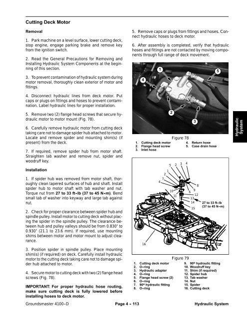
1. Cutting deck motor<br />
2. Flange head screw<br />
3. Inlet hose<br />
16<br />
7<br />
4<br />
1<br />
2<br />
2<br />
10<br />
1. Cutting deck motor<br />
2. O -ring<br />
3. Hydraulic adapter<br />
4. O -ring<br />
5. Flange head screw (2)<br />
6. O -ring<br />
7. 90 o hydraulic fitting<br />
8. O -ring<br />
Figure 78<br />
5 2<br />
11<br />
3<br />
3<br />
4. Return hose<br />
5. Case drain hose<br />
4<br />
8<br />
9<br />
6<br />
12<br />
13<br />
14<br />
15<br />
27 to 33 ft -lb<br />
(37to45N-m)<br />
Figure 79<br />
9. 90 o hydraulic fitting<br />
10. Woodruff key<br />
11. Shim (if required)<br />
12. Spider hub<br />
13. Tab washer<br />
14. Nut<br />
15. Spider<br />
16. Cutting deck<br />
Hydraulic System<br />
Hydraulic<br />
System


