

caution - Toro
caution - Toro
caution - Toro

You also want an ePaper? Increase the reach of your titles
YUMPU automatically turns print PDFs into web optimized ePapers that Google loves.
9. Disconnect throttle cable from the speed control lever<br />
by removing the flat washer and lock nut (Fig. 14).<br />
Loosen jam nut and separate cable from cable support.<br />
Position cable away from engine.<br />
1<br />
10.Remove fasteners that secure the upper radiator<br />
shroud to the lower shroud and radiator (see Radiator<br />
Removal in this section). Position coolant reservoir and<br />
bracket away from the radiator. Remove upper radiator<br />
shroud from machine.<br />
3<br />
11.Remove fan hub and fan from hydraulic fan motor<br />
(Fig. 15).<br />
A. Remove hex nut (item 9) and washer (item 8) that<br />
secure fan hub and fan assembly to fan motor.<br />
NOTE: The fan motor shaft is tapered.<br />
B. Use suitable puller to remove fan hub (with fan attached)<br />
from fan motor shaft taking care to not damage<br />
fan. Remove fan hub and fan from machine.<br />
IMPORTANT: The hydraulic pump assembly can remain<br />
in machine during engine removal. To prevent<br />
pump from shifting or falling, make sure to support<br />
pump assembly before mounting fasteners are removed.<br />
12.Support hydraulic pump assembly. Remove fasteners<br />
that secure pump assembly to engine (see Pump<br />
Assembly Removal in the Service and Repairs section<br />
of Chapter 4 -- Hydraulic System).<br />
13.Make sure all cable ties securing the wiring harness,<br />
fuel lines or hydraulic hoses to the engine are removed.<br />
14.Connect hoist or lift to the lift tabs on engine.<br />
15.Remove flange nuts, rebound washers and cap<br />
screws securing the engine mounts to the engine supports.<br />
1. Fuel pump<br />
2. Fuel supply hose<br />
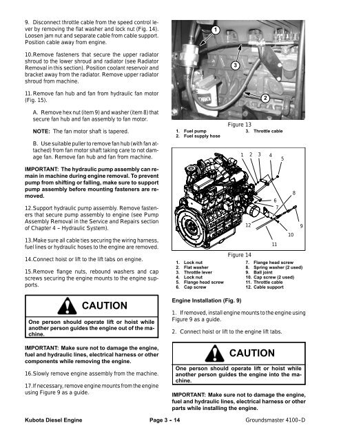
1. Lock nut<br />
2. Flat washer<br />
3. Throttle lever<br />
4. Lock nut<br />
5. Flange head screw<br />
6. Cap screw<br />
Figure 13<br />
1<br />
3. Throttle cable<br />
12<br />
Figure 14<br />
2<br />
2 3 4<br />
6<br />
7<br />
11<br />
7. Flange head screw<br />
8. Spring washer (2 used)<br />
9. Ball joint<br />
10. Cap screw (2 used)<br />
11. Throttle cable<br />
12. Cable support<br />
5<br />
10<br />
8<br />
9<br />
CAUTION<br />
One person should operate lift or hoist while<br />
another person guides the engine out of the machine.<br />
IMPORTANT: Make sure not to damage the engine,<br />
fuel and hydraulic lines, electrical harness or other<br />
components while removing the engine.<br />
16.Slowly remove engine assembly from the machine.<br />
17.If necessary, remove engine mounts from the engine<br />
using Figure 9 as a guide.<br />
Engine Installation (Fig. 9)<br />
1. If removed, install engine mounts to the engine using<br />
Figure 9 as a guide.<br />
2. Connect hoist or lift to the engine lift tabs.<br />
CAUTION<br />
One person should operate lift or hoist while<br />
another person guides the engine into the machine.<br />
IMPORTANT: Make sure not to damage the engine,<br />
fuel and hydraulic lines, electrical harness or other<br />
parts while installing the engine.<br />
Kubota Diesel Engine<br />
Page 3 - 14<br />
Groundsmaster 4100--D


