

caution - Toro
caution - Toro
caution - Toro

Create successful ePaper yourself
Turn your PDF publications into a flip-book with our unique Google optimized e-Paper software.
3. Slowly lower engine into the machine.<br />
4. Align engine to the engine supports and hydraulic<br />
pump input shaft. Secure engine to engine supports with<br />
cap screws, rebound washers and flange nuts.<br />
5. Secure hydraulic pump assembly to engine (see<br />
Pump Assembly Installation in the Service and Repairs<br />
section of Chapter 4 -- Hydraulic System).<br />
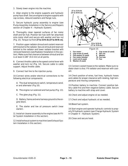
6. Thoroughly clean tapered surfaces of fan motor<br />
shaft and fan hub. Position fan hub (with fan attached)<br />
onto motor shaft and secure with washer and hex nut<br />
(Fig. 15). Torque nut from 27 to 33 ft -lb (37 to 44 N -m).<br />
7. Position upper radiator shroud and coolant reservoir<br />
with bracket to the radiator. Secure shroud and reservoir<br />
bracket to the radiator and lower radiator bracket with<br />
removed fasteners (see Radiator Installation in this section).<br />
Make sure that clearance between shroud and fan<br />
is at least 0.180” (4.6 mm) at all points.<br />
8. Connect throttle cable to the speed control lever with<br />
washer and lock nut (Fig. 14). Secure cable to cable<br />
support. Adjust throttle cable.<br />
9. Connect fuel line to the injection pump.<br />
10.Connect wires and/or electrical connections to the<br />
following electrical components:<br />
A. The dual temperature switch, temperature sender<br />
and alternator (Fig 10).<br />
B. The engine run solenoid and fuel pump (Fig. 13).<br />
C. The glow plug (Fig. 11).<br />
D. Battery, frame and wire harness ground to the engine<br />
block.<br />
E. The starter and low oil pressure switch (near<br />
starter).<br />
11.Install air cleaner assembly to the engine (see Air Filter<br />
System Installation in this section).<br />
12.Install exhaust system to machine (see Exhaust System<br />
Installation in this section).<br />
27 to 33 ft -lb<br />
(37to44N-m)<br />
10<br />
11<br />
8 9<br />
7<br />
6<br />
1. Fan motor<br />
2. Cap screw (2 used)<br />
3. Flat washer (2 used)<br />
4. Fan motor bracket<br />
5. Lock nut (2 used)<br />
6. Washer (4 used)<br />
12 to 14 ft -lb<br />
(17to18N-m)<br />
Figure 15<br />
5 4<br />
1<br />
7. Cap screw (4 used)<br />
8. Hex nut<br />
9. Washer<br />
10. Fan hub<br />
11. Fan<br />
13.Connect coolant hoses to the radiator. Make sure radiator<br />
drain is shut. Fill radiator and reservoir with coolant.<br />
14.Check position of wires, fuel lines, hydraulic hoses<br />
and cables for proper clearance with rotating, high temperature<br />
and moving components.<br />
15.Position battery to machine. Connect positive battery<br />
cable first and then negative battery cable. Secure<br />
battery to machine with strap and cover.<br />
16.Check and adjust engine oil as needed.<br />
17.Check and adjust hydraulic oil as needed.<br />
18.Bleed fuel system.<br />
19.Start engine and operate hydraulic controls to properly<br />
fill hydraulic system (see Charge Hydraulic System<br />
in Chapter 4 -- Hydraulic System).<br />
20.Close and secure hood.<br />
3<br />
2<br />
Kubota<br />
Diesel Engine<br />
Groundsmaster 4100--D Page 3 - 15 Kubota Diesel Engine


