habegger thread rolling dies - Floyd Automatic Tooling Ltd
habegger thread rolling dies - Floyd Automatic Tooling Ltd
habegger thread rolling dies - Floyd Automatic Tooling Ltd

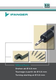
You also want an ePaper? Increase the reach of your titles
YUMPU automatically turns print PDFs into web optimized ePapers that Google loves.
HABEGGER UK LTD<br />
A FLOYD AUTOMATIC TOOLING ASSOCIATE<br />
COMPANY<br />
GENERAL INFORMATION:<br />
HABEGGER THREAD ROLLING DIES<br />
20 GENERAL REMARKS<br />
There are two types of Habegger <strong>thread</strong> <strong>rolling</strong> <strong>dies</strong>, i.e.:<br />
1) Adjustable <strong>thread</strong> <strong>rolling</strong> <strong>dies</strong><br />
2) Non-adjustable <strong>thread</strong> <strong>rolling</strong> <strong>dies</strong><br />
20.1 Main advantages of <strong>thread</strong> <strong>rolling</strong>:<br />
- Better <strong>thread</strong> quality<br />
- High machining regularity<br />
- Increased <strong>thread</strong> resistance<br />
- Reduced breaking points<br />
- Better surface values on the <strong>thread</strong> flanks and on the <strong>thread</strong> root.<br />
20.2 Habegger <strong>thread</strong> <strong>rolling</strong> <strong>dies</strong> are used with success for watch and<br />
instruments screws, spectacle screws etc. They are highly recommended for<br />
stainless steel screws.<br />
20.3 Thread <strong>rolling</strong> will not be possible with materials like lead or synthetics, with<br />
cast iron or other easily breaking materials.<br />
20.4 Materials for which the use of Habegger <strong>thread</strong> <strong>rolling</strong> <strong>dies</strong> are considered<br />
as economical production means, are divided in 4 groups:<br />
1) Smooth materials: smooth steel, brass, nickel silver, and aluminium<br />
2) Half-hard materials: 20 AP steel (basic material to check the<br />
Non-adjustable <strong>thread</strong> <strong>rolling</strong> <strong>dies</strong>)<br />
3) Hard materials: stainless steel<br />
4) Extreme materials: Titanium<br />
TEL: 01462 491919 FAX: 01462 490835 E: <strong>habegger</strong>uk@floydautomatic<br />
1
20.5 Thread <strong>rolling</strong> with Habegger <strong>rolling</strong> <strong>dies</strong> is done with the same ratios as for<br />
cutting <strong>dies</strong>.<br />
20.6 The peripheral speed of the work piece will be between 20 - 50 m/min.<br />
21 ADJUSTABLE THREAD ROLLING DIES<br />
21.1 Description<br />
These adjustable Habegger <strong>thread</strong> <strong>rolling</strong> <strong>dies</strong> include 7 elements, i.e.:<br />
- 1 body (1)<br />
- 3 rollers (2)<br />
- 3 studs (3)<br />
21.2 These <strong>rolling</strong> <strong>dies</strong> are recommended for machining small and medium<br />
work piece batches.<br />
21.3 The diameter on the <strong>thread</strong> flank can be adjusted by means of the nut of<br />
type R die holders. The outside diameter is adjusted by modifying the turning<br />
diameter before <strong>thread</strong> <strong>rolling</strong>. Take care that the <strong>thread</strong> is not full and that<br />
a slight flat remains on top of the profile.<br />
21.4 These <strong>dies</strong> permit to compensate the wear on rollers and studs, but they<br />
need more attention from the operator.<br />
21.5 We supply spare parts (rollers) for this kind of die, as the operator does the<br />
final adjustment.<br />
21.6 Die holders<br />
Adjustable <strong>thread</strong> <strong>rolling</strong> <strong>dies</strong> are assembled onto the machines by means of<br />
R-type die holders (see general catalogue).<br />
21.7 Threading in second operation<br />
All <strong>thread</strong>ing effected, as second operations must be done with adjustable<br />
<strong>thread</strong> <strong>rolling</strong> <strong>dies</strong>.<br />
TEL: 01462 491919 FAX: 01462 490835 E: <strong>habegger</strong>uk@floydautomatic<br />
2
22 NON-ADJUSTABLE THREAD ROLLING DIES<br />
22.1 Description<br />
Habegger non-adjustable <strong>thread</strong> <strong>rolling</strong> <strong>dies</strong> include 7 elements, i.e.:<br />
- 1 body (1)<br />
- 3 rollers (2)<br />
- 3 studs (3)<br />
22.2 Their use is recommended for large batches of work pieces.<br />
22.3 They are available in hundredths of millimetres (0.01 mm) in the usual<br />
<strong>thread</strong>ing tolerances.<br />
22.4 These non-adjustable <strong>thread</strong> <strong>rolling</strong> <strong>dies</strong> are supplied for a diameter<br />
determined by the tolerances of the work piece <strong>thread</strong>. The tolerances<br />
and the material must be indicated at order. When working, the diameter of<br />
the <strong>dies</strong> will slightly increase. It is therefore advised to choose <strong>dies</strong> to the<br />
minimum of the tolerances.<br />
Example: work piece: 0.90+0/-0.02<br />
Die: 0.885<br />
22.5 When the customer uses the non-adjustable Habegger <strong>thread</strong> <strong>rolling</strong> <strong>dies</strong> for<br />
the first time, we supply <strong>dies</strong> that are slightly over the minimum tolerance, in<br />
order to avoid breakage of the rollers due to filling up the teeth to their<br />
maximum.<br />
22.6 These <strong>dies</strong> have the advantage to be independent from a false adjustment by<br />
the inattention of the operator. However, contrarily to adjustable <strong>dies</strong>, their<br />
lifetime is directly bound to the wear of the rollers and studs.<br />
22.7 All non-adjustable <strong>dies</strong> are tested in 20 AP steel. We could establish an<br />
equality rule. For example, if the equality is 0.59 for 20 AP steel, we will<br />
supply an equality of 0.58 for stainless steel and of 0.60 for smooth turning steel.<br />
If the material is tougher than the test material, the rollers will have a tendency<br />
to spread out a little more. Inversely, if the material is smoother.<br />
22.8 Die holders<br />
Non-adjustable <strong>dies</strong> are assembled onto the machines by means of 3 types of<br />
die holders: type N, F and V (see general catalogue).<br />
22.9 We don't supply spare parts for non-adjustable <strong>thread</strong> <strong>rolling</strong> <strong>dies</strong>, except in<br />
some special cases but without guarantee, for reasons of roller tolerances<br />
TEL: 01462 491919 FAX: 01462 490835 E: <strong>habegger</strong>uk@floydautomatic<br />
3
23 MULTIPLE THREADS<br />
23.1 Double <strong>thread</strong> (2 start)<br />
Dies for double <strong>thread</strong>s are available. to order, we imperatively need to know<br />
if the indicated pitch is real or apparent:<br />
Example: MDP 6.00 x 1.00<br />
Real pitch: 1 pitch = 1 mm<br />
Apparent pitch: ½ pitch = 0.5 mm<br />
23.2 Triple <strong>thread</strong> (3 start)<br />
Also <strong>dies</strong> for triple <strong>thread</strong>s are available.<br />
24 THREAD ROLLING ON TUBES<br />
It is possible to roll <strong>thread</strong>s on tubes with the Habegger <strong>thread</strong> <strong>rolling</strong> <strong>dies</strong>, in<br />
so far as the tube walls are solid enough. The tube will have a tendency to<br />
close. The material will yield toward the centre.<br />
25 L. H. THREADS<br />
All the <strong>dies</strong> are available for L. H. <strong>thread</strong>ing (type "L").<br />
26 SPECIAL PROFILES<br />
On demand, all kinds of dimensions and profiles can be studied, according to<br />
the customer's needs.<br />
TEL: 01462 491919 FAX: 01462 490835 E: <strong>habegger</strong>uk@floydautomatic<br />
4
27 CLEARED-OFF STUDS<br />
27.1 Description<br />
On demand, we supply <strong>thread</strong> <strong>rolling</strong> <strong>dies</strong> with cleared-off studs to let pass the<br />
screw head, as sketched below:<br />
A = Bar passage diameter between studs, without clearance.<br />
B = Bar passage diameter after clearance of the studs.<br />
C = Unrolled shaft-length when the bar diameter exceeds the passing diameter<br />
between studs.<br />
D = Outside diameter of the <strong>thread</strong> <strong>rolling</strong> die.<br />
D1 = Adjustable die<br />
D2 = Non-adjustable die<br />
∅ of <strong>thread</strong> x pitch A B C D1 D2<br />
M 0.40 x 0.10 0.70 1.60 0.40 -- 6<br />
M 0.50 x 0.125 0.90 2.00 0.50 -- 6<br />
M 0.60 x 0.15 1.20 2.60 0.60 8 6<br />
M 0.70 x 0.175 1.60 3.00 0.60 8 6<br />
M 0.80 x 0.20 1.70 3.50 0.80 8 8<br />
M 0.90 x 0.225 1.70 3.70 0.90 8 8<br />
M 1.00 x 0.25 2.00 4.10 0.90 10 8<br />
M 1.10 x 0.25 2.10 4.20 0.90 10 8<br />
M 1.20 x 0.25 2.20 4.30 0.90 10 8<br />
M 1.30 x 0.30 2.40 4.60 0.90 10 8/10<br />
M 1.40 x 0.30 2.50 4.70 0.90 10 8/10<br />
M 1.50 x 0.30 2.60 4.80 0.90 10 8/10<br />
M 1.60 x 0.35 3.60 6.20 1.10 14 12<br />
M 1.70 x 0.35 3.70 6.30 1.10 14 12<br />
M 1.80 x 0.35 3.80 6.40 1.10 14 12<br />
M 2.00 x 0.40 4.00 6.80 1.10 14 12<br />
M 2.20 x 0.45 4.40 7.80 1.20 16 12/16<br />
M 2.50 x 0.45 4.70 8.10 1.20 16 12/16<br />
M 2.60 x 0.45 4.80 8.20 1.20 16 12/16<br />
M 3.00 x 0.50 PM 5.10 8.50 1.30 16 12/16<br />
M 3.00 x 0.50 GM 7.30 12.00 2.00 25 22<br />
M 3.50 x 0.60 7.70 12.40 2.10 25 22<br />
M 4.00 x 0.70 8.00 12.80 2.20 25 22<br />
M 4.50 x 0.75 8.30 13.20 2.20 25 25<br />
M 5.00 x 0.80 9.00 14.00 2.30 27 25<br />
M 6.00 x 1.00 10.70 16.50 2.70 32 30<br />
M 7.00 x 1.00 11.70 17.50 2.70 32 --<br />
M 8.00 x 1.25 12.60 19.50 3.50 35 --<br />
TEL: 01462 491919 FAX: 01462 490835 E: <strong>habegger</strong>uk@floydautomatic<br />
5
28 DIE HOLDERS<br />
To complete the range of our standard die holder’s types R, N, F and V, we<br />
propose also the following types:<br />
28.1 Die holder with compensating system<br />
When the <strong>thread</strong> <strong>rolling</strong> <strong>dies</strong> are used on fixed headstock turning machines or<br />
on CNC machines, a die holder with compensating system must be chosen.<br />
This Habegger system permits to compensate the feed differences between the<br />
die (according to the pitch) and the machine.<br />
At the engagement and during the whole <strong>thread</strong>ing operation, the machines’<br />
feed will be slightly lower than the pitch/rotation ratio. The pitch is only<br />
given by the <strong>thread</strong> <strong>rolling</strong> die, without external stress.<br />
The return spring permits this compensation.<br />
The working feed is calculated as follows: pitch x 0.98.<br />
28.2 Habegger die holders for ESCO machines<br />
When the <strong>dies</strong> must be used on ESCO machines of the type D2GR43 and<br />
D6R, we supply the die holders corresponding to each of the said machines.<br />
29 ENGAGING ANGLE AND TURNING DIAMETER<br />
29.1 To have an easier engagement of the <strong>rolling</strong> die on the work piece, it is necessary to<br />
form an angle of 15 to 20° at the front of the <strong>thread</strong>. The start effort is then reduced.<br />
The same angle must be formed at the end of the <strong>thread</strong> if the work piece has an<br />
undercut. The longer the angle is, the more the conditions get better.<br />
29.2 The blank turning of the work piece will be done as per indicative chart below:<br />
Thread <strong>rolling</strong> die:M 0.35 0.40 0.50 0.60 0.70 0.80 0.90 1.00 1.10<br />
Diameter "D”: 0.27 0.31 0.39 0.40 0.57 0.65 0.74 0.80 0.90<br />
Thread <strong>rolling</strong> die:M 1.20 1.30 1.40 1.50 1.60 1.70 1.80 2.00 2.20<br />
Diameter "D”: 1.00 1.05 1.15 1.25 1.30 1.40 1.50 1.60 1.75<br />
Thread <strong>rolling</strong> die:M 2.50 3.00 3.50 4.00 4.50 5.00 6.00 8.00<br />
Diameter "D”: 2.05 2.50 2.90 3.35 3.80 4.25 5.10 6.95<br />
This blank diameter will be increased progressively, until a slight flat remains on top<br />
of the <strong>thread</strong>. This flat must always be kept to avoid filling up with material or even<br />
spoiling the die.<br />
TEL: 01462 491919 FAX: 01462 490835 E: <strong>habegger</strong>uk@floydautomatic<br />
6
9.3 Programme example for <strong>thread</strong> <strong>rolling</strong> on a CNC sliding head machine using<br />
the compensating system with an M6 x 1 <strong>thread</strong>. (Values will need to be programmed<br />
according to application.)<br />
G0 Z3.0 S1200 M03 (Rapid approach to front of part & set spindle speed)<br />
G1 Z-5.0 F0.98 (Feed on to engage die at 98% of pitch)<br />
M04<br />
(Spindle reverse)<br />
G1 Z5.0 F1.0 (Feed off at pitch to disengage die)<br />
G0 Z10.<br />
(Rapid retract to clearance position)<br />
Note! Do not use rigid tapping cycle as this will not work for <strong>thread</strong> <strong>rolling</strong><br />
30 STARTING CAM WHEN USING CAM CONTROLLED MACHINE<br />
30.1 To get the best use of Habegger <strong>thread</strong> <strong>rolling</strong> <strong>dies</strong>, the working angle of the<br />
engaging cam must be calculated. The compensation spring of the <strong>thread</strong>ing<br />
spindle must be taken off. The start angle can be cut with a file. It is calculated<br />
as follows (cam controlled machines):<br />
For lever ratio 1:1<br />
V = Difference of RPM between headstock spindle and attachment spindle<br />
P = Pitch of the work piece, in mm<br />
n = Production (number of parts per minute)<br />
d = Diameter of the starting cam in mm.<br />
Formula:<br />
V · P<br />
———— = tg a<br />
n · d · π<br />
TEL: 01462 491919 FAX: 01462 490835 E: <strong>habegger</strong>uk@floydautomatic<br />
7
30.2 Practical example:<br />
Headstock speed: 5000 min -1<br />
Speed of attachment spindle: 6000 min -1<br />
Production: 3 pieces/min<br />
Diameter of starting cam: 95 mm<br />
Pitch of work piece: 0.5 mm<br />
V · P (6000-5000) · 0.5 500<br />
———— = ———————— = ——— = tg 0.558 = 29.2°<br />
n · d · π 3 · 95 · π 895.3<br />
30.3 To make machining the cam easier, we can represent the triangle on a<br />
squared paper. Cut off the triangle and transfer it to the cam to mark out<br />
the angle.<br />
31 DIFFICULTY ENGAGING START<br />
If the start is difficult or if the slope on the cam is too fast, causing the<br />
deflection of the levers and a bad engaging of the die, the engaging thrust must<br />
be parted off between headstock feed and starting cam.<br />
V =<br />
P =<br />
n =<br />
d =<br />
Difference of RPM between headstock spindle and attachment spindle<br />
Pitch of the work piece, in mm<br />
Production (number of parts per minute)<br />
Diameter of the starting cam in mm<br />
Example: V = 1000 min -1<br />
P = 0.5 mm<br />
n = 2 pces/minute<br />
d = 95 mm<br />
1000 · 0.5 500<br />
————— = ——— = tg 0.838 = 39.95°<br />
2 · 95 · π 596.9<br />
That slope is too fast. We part it off as follows:<br />
TEL: 01462 491919 FAX: 01462 490835 E: <strong>habegger</strong>uk@floydautomatic<br />
8
Example:<br />
VS (headstock speed): 5000 min-1<br />
C (headstock feed): 0.05 mm/tour<br />
Total feed: V · P = 1000 · 0.5 = 500 mm<br />
Headstock feed: VS · C = 5000 · 0.05 = 250 mm<br />
Difference of the feeds: 500 - 250 = 250 mm<br />
250<br />
Headstock cam : ————— = tg 0.419 = 22.7°<br />
2 · 95 · π<br />
250<br />
Starting cam: ————— = tg 0.419 = 22.7°<br />
2 · 95 · π<br />
TEL: 01462 491919 FAX: 01462 490835 E: <strong>habegger</strong>uk@floydautomatic<br />
9