REV24RF Set Datasheet - Industry UK - Siemens
REV24RF Set Datasheet - Industry UK - Siemens
REV24RF Set Datasheet - Industry UK - Siemens

Create successful ePaper yourself
Turn your PDF publications into a flip-book with our unique Google optimized e-Paper software.
s<br />
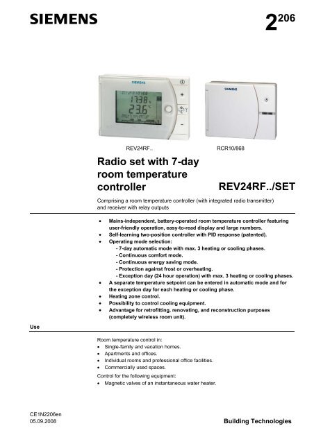
2 206<br />
<strong>REV24RF</strong>..<br />
Radio set with 7-day<br />
room temperature<br />
controller<br />
RCR10/868<br />
<strong>REV24RF</strong>../SET<br />
Comprising a room temperature controller (with integrated radio transmitter)<br />
and receiver with relay outputs<br />
• Mains-independent, battery-operated room temperature controller featuring<br />
user-friendly operation, easy-to-read display and large numbers.<br />
• Self-learning two-position controller with PID response (patented).<br />
• Operating mode selection:<br />
- 7-day automatic mode with max. 3 heating or cooling phases.<br />
- Continuous comfort mode.<br />
- Continuous energy saving mode.<br />
- Protection against frost or overheating.<br />
- Exception day (24 hour operation) with max. 3 heating or cooling phases.<br />
• A separate temperature setpoint can be entered in automatic mode and for<br />
the exception day for each heating or cooling phase.<br />
• Heating zone control.<br />
• Possibility to control cooling equipment.<br />
• Advantage for retrofitting, renovating, and reconstruction purposes<br />
(completely wireless room unit).<br />
Use<br />
Room temperature control in:<br />
• Single-family and vacation homes.<br />
• Apartments and offices.<br />
• Individual rooms and professional office facilities.<br />
• Commercially used spaces.<br />
Control for the following equipment:<br />
• Magnetic valves of an instantaneous water heater.<br />
CE1N2206en<br />
05.09.2008 Building Technologies
• Magnetic valves of an atmospheric gas burner.<br />
• Forced draught gas and oil burners.<br />
• Electrothermal actuators.<br />
• Circulating pumps in heating systems.<br />
• Electric direct heating.<br />
• Fans of electric storage heaters.<br />
• Zone valves (normally open and normally closed).<br />
• Air conditioning and cooling equipment.<br />
Function<br />
• Bidirectional radio transmission.<br />
• PID control with self-learning or selectable switching cycle time.<br />
• 2-point control.<br />
• 7-day time switch.<br />
• Preselected 24-hour operating modes.<br />
• Override function.<br />
• Holiday mode.<br />
• Party mode.<br />
• Protection function (protection against frost or overheating).<br />
• Information level to check settings.<br />
• Reset function.<br />
• Sensor calibration.<br />
• Heating or cooling.<br />
• Minimum limitation of setpoint.<br />
• Periodic pump run.<br />
Protection against valve seizure.<br />
• Optimum start control in the morning (P.1).<br />
• Synchronization to radio time signal from Frankfurt, Germany (<strong>REV24RF</strong>DC).<br />
• Manual override of the receiving relay.<br />
Type summary<br />
Radio set comprising:<br />
- Room temperature controller <strong>REV24RF</strong> with 7-day time switch,<br />
Base and receiver RCR10/868<br />
<strong>REV24RF</strong>/SET<br />
Radio set comprising<br />
- Room temperature controller <strong>REV24RF</strong>DC with 7-day time switch,<br />
Receiver for time signal from Frankfurt, Germany (DCF77),<br />
Base and receiver RCR10/868<br />
<strong>REV24RF</strong>DC/SET<br />
Ordering<br />
Please indicate the type number as per the "Type summary" when ordering.<br />
Delivery<br />
The controller/transmitter <strong>REV24RF</strong>.. is delivered with batteries.<br />
Mechanical design<br />
Room controller and<br />
base<br />
Base and<br />
table stand<br />
Plastic casing with an easy-to-read display and large numbers, easily accessible<br />
operating elements, and removable base. The casing accommodates the electronics<br />
with the DIP switches. The easily accessible battery compartment allows for easy<br />
exchange of two 1.5 V alkaline batteries, type AA.<br />
The base helps attach the room controller to the wall. The supplied table stand allows<br />
you to stand the controller anywhere in the room. You can manually attach the table<br />
stand without tools.<br />
2 / 18<br />
<strong>Siemens</strong> Room temperature controller radio set <strong>REV24RF</strong>../SET CE1N2206en<br />
Building Technologies 05.09.2008
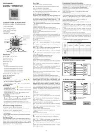
Receiver<br />
Display and operating<br />
elements<br />
Plastic housing with large operating elements, removable cover and easily accessible<br />
terminal block with lots of space to attach the wires. You can mount and wire the unit on<br />
most commercially available recessed conduit boxes or directly on the wall. The<br />
potential-free changeover contact and the antenna for reception are integrated in the<br />
unit.<br />
1 Display<br />
Change battery<br />
Alarm<br />
Heating mode<br />
Cooling mode<br />
Weekday (max. 3 spaces)<br />
0 4 8 12 16 20 24<br />
Time of day<br />
Room temperature (measured)<br />
Clear text display line<br />
(max. 18 spaces)<br />
24 hour timeframe with<br />
switching pattern with flashing<br />
time cursor<br />
Without language selection<br />
Info<br />
Info<br />
<strong>Set</strong>point for comfort mode<br />
Weekday block<br />
Weekend block<br />
Weekday<br />
<strong>Set</strong>point for absence h Time unit<br />
Room temperature<br />
<strong>Set</strong>point for frost protection<br />
mode<br />
Energy saving mode setpoint<br />
Absence/holiday mode set<br />
Absence/holiday mode active<br />
Party mode active<br />
Time signal from Frankfurt °C / °F Temperature unit °C or °F<br />
Date (day - month - year)<br />
Heating/cooling/pump on<br />
3 / 18<br />
<strong>Siemens</strong> Room temperature controller radio set <strong>REV24RF</strong>../SET CE1N2206en<br />
Building Technologies 05.09.2008
2 Operating mode selector<br />
Automatic weekly mode with max. three heating or cooling phases per<br />
day.<br />
Exception day with max. three heating or cooling phases.<br />
Continuous comfort mode (= continuous comfort temperature).<br />
Continuous energy saving mode (= continuous energy saving<br />
temperature).<br />
Protection mode (protection against frost or overheating).<br />
3 INFO<br />
Pressing the Info button once illuminates the display. Illumination<br />
automatically turns off after a short period of time.<br />
Pressing the Info button again activates the information display:<br />
The unit first displays queued error messages followed by important<br />
information (e.g. time switch programs, etc.).<br />
is lit.<br />
4 Plus button<br />
Increase values, set time, or make a selection.<br />
5 Override button / party mode<br />
In the time switch program, this button allows you to quickly change from the<br />
active temperature level to the next and back.<br />
Thus, you can quickly change to energy saving temperature when you leave<br />
the apartment for a short period of time, thus saving energy.<br />
The display indicates the change. It is valid only until the next switching time.<br />
rty mode: Press the button for 3 seconds.<br />
Party mode is available only in operating modes and . In party mode,<br />
the controller controls to a freely selectable temperature for a freely<br />
selectable period of time.<br />
In party mode, symbol<br />
is displayed along with the end of party mode.<br />
6 Minus button<br />
Decrease values, set time, or make a selection.<br />
4 / 18<br />
<strong>Siemens</strong> Room temperature controller radio set <strong>REV24RF</strong>../SET CE1N2206en<br />
Building Technologies 05.09.2008
7 Program selection slider<br />
Time<br />
Day – Month – Year (2 spaces for day, month, and year).<br />
Weekday, weekend, or individual day blocks.<br />
1, 2, or 3 comfort phases.<br />
Start<br />
Comfort phase 1<br />
<strong>Set</strong>point<br />
Comfort phase 1<br />
End<br />
Comfort phase 1<br />
Start<br />
Comfort phase 2<br />
<strong>Set</strong>point<br />
Comfort phase 2<br />
End<br />
Comfort phase 2<br />
Start<br />
Comfort phase 3<br />
<strong>Set</strong>point<br />
Comfort phase 3<br />
End<br />
Comfort phase 3<br />
Energy saving temperature in the automatic mode and exception day time<br />
switch programs.<br />
Start of absence.<br />
Temperature setpoint during absence.<br />
End of absence.<br />
RUN<br />
Slider position RUN allows for closing the cover.<br />
Operating modes<br />
Operation with<br />
time switch program<br />
The controller offers the two time switch programs and .<br />
Enter a start time and end time for each comfort phase. Also comfort temperature<br />
setpoint can be freely entered for each comfort phase. Between the comfort phases<br />
the controller always switches to the same, freely selectable energy saving<br />
temperature setpoint.<br />
°C<br />
Example with<br />
3 heating phases<br />
22<br />
21<br />
20<br />
Heating<br />
phase 1<br />
Heating<br />
phase 2<br />
Heating phase 3<br />
18<br />
16<br />
2205Z04<br />
06 08 12 14<br />
18 22 h<br />
Continuous operating<br />
modes<br />
The controller also offers the three 3 continuous modes<br />
energy saving mode and<br />
frost protection mode.<br />
comfort mode,<br />
5 / 18<br />
<strong>Siemens</strong> Room temperature controller radio set <strong>REV24RF</strong>../SET CE1N2206en<br />
Building Technologies 05.09.2008
<strong>Set</strong>points<br />
You can freely adjust the setpoints for the weekly and 24-hour operating modes.<br />
<strong>Set</strong>ting range for all setpoints without setpoint limitation 3…35 °C.<br />
<strong>Set</strong>ting range for all setpoints with setpoint limitation 16…35 °C.<br />
Factory setting<br />
Factory setting for heating<br />
Factory setting for cooling<br />
, , , 20 °C 24 °C<br />
, 16 °C 28 °C<br />
8 °C 35 °C<br />
12 °C 30 °C<br />
Factory settings: Switching times<br />
Comfort phases P1 P2 P3 P4 P5 P6<br />
1. 07:00 23:00 PASS PASS PASS PASS<br />
2. 06:00 08:00 17:00 22:00 PASS PASS<br />
3. 06:00 08:00 11:00 13:00 17:00 22:00<br />
7-day time switch<br />
Three different switching patterns are available to simplify entry of switching times. These<br />
can be assigned as blocks to the corresponding weekdays 1…5 and weekend days<br />
6…7. As a result, you need to adapt the switching times and room temperatures only<br />
once for each block.<br />
Switching pattern<br />
Blocks<br />
You can also enter individual days … .<br />
Enter holidays or<br />
absences<br />
You can enter the beginning, temperature and end of your holidays. At the beginning of<br />
the holidays, the controller switches to the desired holiday temperature and returns to the<br />
previously set operating mode at the end of the holidays.<br />
In holiday mode, symbol is displayed along with the end of holiday mode.<br />
Proceed as follows to enter your settings:<br />
<strong>Set</strong> slider to position 15 (start of absence): Press or to set the start date<br />
for your holidays.<br />
<strong>Set</strong> slider to position 16 (temperature during absence): Press or to set<br />
the desired temperature while on holidays.<br />
<strong>Set</strong> slider to position 17 (end of absence): Press or to set the end date<br />
for your holidays.<br />
RUN<br />
Return the slider to position RUN. Symbol is displayed to the left of the<br />
symbol.<br />
Press , , , or move the slider to end holiday mode prematurely.<br />
6 / 18<br />
<strong>Siemens</strong> Room temperature controller radio set <strong>REV24RF</strong>../SET CE1N2206en<br />
Building Technologies 05.09.2008
Technical features<br />
DIP switches<br />
DIP switch ON / OFF 1 2 3 4 5 6 7 8 9 10<br />
Sensor calibration On<br />
A<br />
Sensor calibration Off<br />
Periodic pump run and<br />
anti-lime function On<br />
Periodic pump run and<br />
anti-lime function Off<br />
<strong>Set</strong>point limitation 16…35 °C<br />
Start optimization: 1 h/°C<br />
B<br />
<strong>Set</strong>point limitation 3…35 °C<br />
Start optimization: ¼ h/°C<br />
F<br />
Temperature display °F<br />
Start optimization: ½ h/°C<br />
C<br />
Temperature display °C Start optimization: Off<br />
E<br />
PID self-learning<br />
PID 6<br />
D<br />
PID12<br />
2-point<br />
(Op. mode: Cooling)<br />
(Op. mode: Heating)<br />
Quartz<br />
Radio clock<br />
G<br />
H<br />
J<br />
1 2 3 4 5 6 7 8 9<br />
DIP switch reset<br />
After you change one or several DIP switch positions, you must press the DIP switch reset button to reset the DIP<br />
switch. Otherwise, the previous setting remains active!<br />
Factory setting: All DIP switches to<br />
ON<br />
2211Z32<br />
OFF<br />
J<br />
A Sensor calibration:<br />
DIP switch 1<br />
B <strong>Set</strong>point limitation:<br />
DIP switch 2<br />
C Temperature display in<br />
°C or °F:<br />
DIP switch 3<br />
D Control behavior:<br />
DIP switches 4 and 5<br />
If the displayed room temperature does not match the measured room temperature, the<br />
temperature sensor can be recalibrated.<br />
<strong>Set</strong> DIP switch to ON and press the DIP switch reset button:<br />
CAL symbol is displayed. The currently measured temperature flashes.<br />
Press or to recalibrate by max. ± 5 °C.<br />
<strong>Set</strong> DIP switch to OFF and press the DIP switch reset button to save the settings.<br />
The minimum setpoint limitation of 16 °C prevents undesired heat transfer to neighboring<br />
spaces in buildings featuring several heating zones.<br />
DIP switch ON: <strong>Set</strong>point limitation 16…35 °C.<br />
DIP switch OFF: <strong>Set</strong>point limitation 3…35 °C (factory setting).<br />
Press the DIP switch reset button to save the settings.<br />
DIP switch ON: Temperature display in °F.<br />
DIP switch OFF: Temperature display in °C (factory setting).<br />
Press the DIP switch reset button to save the settings.<br />
The REV24… is a two-position controller with PID control. The room temperature is<br />
controlled through cyclic switching of an actuating unit.<br />
DIP switches 4 ON and 5 ON: PID self-learning<br />
Adaptive control for all applications.<br />
DIP switches 4 ON and 5 OFF: PID 6<br />
Fast controlled system for applications in locations with<br />
large temperature deviations.<br />
DIP switches 4 OFF and 5 ON: PID 12<br />
Normal controlled system for applications in locations with<br />
normal temperature deviations.<br />
DIP switches 4 OFF and 5 OFF: 2-point<br />
7 / 18<br />
<strong>Siemens</strong> Room temperature controller radio set <strong>REV24RF</strong>../SET CE1N2206en<br />
Building Technologies 05.09.2008
For complex controlled systems, simple two-position controller with<br />
0.5 °C switching difference (factory setting).<br />
Press the DIP switch reset button to save the settings.<br />
E Periodic pump run<br />
and anti-lime function:<br />
DIP switch 6<br />
F Start optimization:<br />
DIP switches 7 and 8<br />
Only applicable with controlled circulating pump or valve!<br />
This function protects the pump or valve during extended OFF periods against possible<br />
seizure caused by liming. Periodic pump run is activated every 24 hours at 12 p.m. for<br />
three minutes (symbol ▲ is displayed during active pump run).<br />
DIP switch ON: Pump run ON.<br />
DIP switch OFF: Pump run OFF (factory setting).<br />
Press the DIP switch reset button to save the settings.<br />
Optimization advances the switch-on point P.1 to ensure that the selected setpoint is<br />
reached at the desired time. The setting depends on the controlled system, i.e., on heat<br />
transmission (piping system, radiators), building dynamics (building mass, insulation),<br />
and heat output (boiler capacity, flow temperature).<br />
DIP switches 7 ON and 8 ON: 1 h/°C For slow controlled systems.<br />
DIP switches 7 ON and 8 OFF: ¼ h/°C For fast controlled systems.<br />
DIP switches 7 OFF and 8 ON: ½ h/°C For medium controlled systems.<br />
DIP switches 7 OFF and 8 OFF: OFF Off, no effect (factory setting).<br />
Press the DIP switch reset button to save the settings.<br />
T<br />
Pon<br />
°C T1<br />
20<br />
19<br />
TRx<br />
18<br />
17<br />
16<br />
1h/°C - 4 h - 3 h - 2 h - 1 h P.1<br />
1/2h/°C - 2 h - 1½ h - 1 h - ½ h<br />
1/4h/°C - 1 h - ¾ h - ½ h - ¼ h<br />
t<br />
2254D01<br />
Key for diagram:<br />
T Temperature (°C)<br />
t Forward shift of switch-on point (h)<br />
TRx Room temperature actual value<br />
Pon Starting point for optimized heat-up time.<br />
G Operating mode heating<br />
or cooling:<br />
DIP switch 9<br />
H Radio clock:<br />
DIP switch 10<br />
The controller can be switched over for cooling applications on DIP switch 9.<br />
DIP switch 9 ON:<br />
Cooling<br />
DIP switch 9 OFF:<br />
Heating (factory setting).<br />
Press the DIP switch reset button to save the settings.<br />
Only applicable to REV..DC (with integrated DCF77 receiver to receive time signal from<br />
Frankfurt, Germany)!<br />
DIP switch ON: Clock run by controller-internal quartz.<br />
DIP switch OFF:<br />
Time signal DCF77 from Frankfurt, Germany.<br />
Press the DIP switch reset button to save the settings.<br />
Note<br />
on synchronization<br />
During startup, REV..DC synchronizes automatically to the time signal (DCF77) from<br />
Frankfurt, Germany. Synchronization takes max. 10 minutes. Synchronization restarts<br />
each time you press the button or move the program selection slider from the RUN<br />
position during these 10 minutes. <strong>Siemens</strong> recommends to set the desired settings upon<br />
startup, install the REV..DC in the desired location, and not carry out any actions on the<br />
REV..DC for the next 10 minutes.<br />
In normal operation, the REV..DC synchronizes to the radio clock every day at 3:10 a.m.<br />
8 / 18<br />
<strong>Siemens</strong> Room temperature controller radio set <strong>REV24RF</strong>../SET CE1N2206en<br />
Building Technologies 05.09.2008
Note<br />
on reception<br />
No reception<br />
J DIP switch reset<br />
ON<br />
1 2 3 4<br />
5 6 7 8 9<br />
2211Z32<br />
The time signal from Frankfurt is modulated to a radio signal. The reception of this radio<br />
signal depends on the distance to Frankfurt, atmospheric conditions as well as the<br />
location where the REV..DC is installed. <strong>Siemens</strong> cannot guarantee that the REV..DC<br />
can receive the time signal from Frankfurt at any time and any place.<br />
The radio clock symbol is deactivated and an error message is displayed if the clock was not<br />
able to synchronize the time for 7 consecutive days. The controller then runs on the internal<br />
quartz.<br />
After you change one or several DIP switch positions, you must press the DIP switch<br />
reset button to reset the DIP switch.<br />
Otherwise, the previous setting remains active!<br />
Access to the expert level<br />
<strong>Set</strong> the program selection slider to RUN. Press and simultaneously for 3 seconds, release the buttons, and<br />
within 3 seconds press and hold down and simultaneously for 3 seconds, release , and press for another 3<br />
seconds. This releases the engineering settings. is displayed.<br />
The display first shows language selection with Code 00. Press the buttons or to navigate the settings.<br />
Confirm settings by pressing .<br />
Press the operating mode selector to exit the engineering settings.<br />
Code list<br />
Function block Code Name Factory setting Your setting<br />
00 Language English<br />
Basic settings 01 Sensor calibration off<br />
02 Switching differential 2-point 0.5 °C<br />
LCD<br />
optimization<br />
Clock settings<br />
10 Illumination time 10 seconds<br />
11 Background brightness 0<br />
12 Contrast 0<br />
30<br />
Time zone<br />
Deviation from time signal in Frankfurt 0 hours<br />
(Central European Time CET) (see Note 1)<br />
31 Start of daylight saving time (see Note 2) March 31 (03-31)<br />
32 End of daylight saving time (see Note 3) October 31 (10-31)<br />
Note 1:<br />
Note 2:<br />
Note 3:<br />
This entry has no effect if the radio clock either is inactive or not available.<br />
The time signal received from Frankfurt is shifted by the value set in Code 30 (time zone)<br />
if the radio clock is active.<br />
The time is always changed over at 2 a.m. on the Sunday preceding the set date if there<br />
is no radio clock or if it is inactive. The time change is shifted by the value set in Code 30<br />
(time zone) when the radio clock is active.<br />
The time is always changed over at 3 a.m. on the Sunday preceding the set date if there<br />
is no radio clock or if it is inactive.<br />
Functional check<br />
a) Check the display. If there is no display, check insertion and function of the batteries.<br />
b) Operating mode “Continuous comfort mode“ , read displayed temperature.<br />
c) REV.. in heating mode: <strong>Set</strong> the temperature setpoint higher than the displayed room<br />
temperature (see operating instructions).<br />
REV.. in cooling mode: <strong>Set</strong> the temperature setpoint lower than the displayed room<br />
temperature (see operating instructions).<br />
9 / 18<br />
<strong>Siemens</strong> Room temperature controller radio set <strong>REV24RF</strong>../SET CE1N2206en<br />
Building Technologies 05.09.2008
d) The relay and, as a result, the actuating device must switch at the latest after one minute.<br />
Symbol ▲ is displayed. If not displayed:<br />
• Check actuating device and wiring.<br />
• It is possible that in heating mode the room temperature is higher than the set<br />
temperature setpoint (and lower for cooling mode).<br />
e) <strong>Set</strong> the temperature setpoint for operating mode “Continuous comfort mode“ to the<br />
desired value.<br />
f) Select the desired operating mode.<br />
Reset<br />
Room controller<br />
<strong>REV24RF</strong>..:<br />
Temperature controller<br />
data<br />
User-defined settings:<br />
, and simultaneously for 3 seconds:<br />
This resets all temperature and time settings of the program selection slider to default<br />
values (see also "Factory settings" in the operating instructions). The expert settings<br />
remain unchanged.<br />
The clock starts at 12 p.m., the date on 01-01-08 (01 January 2008).<br />
During the reset, all display fields are lit and can be checked accordingly.<br />
All user-defined settings plus expert settings:<br />
ON<br />
2211Z32<br />
1 2 3 4<br />
Press the DIP switch reset button<br />
, and simultaneously for 5<br />
seconds:<br />
After the reset, all factor settings are reloaded. This applies to the program selection<br />
slider as well as to the expert settings.<br />
5 6 7 8 9<br />
Room controller<br />
<strong>REV24RF</strong>..:<br />
Data from faulty<br />
receivers<br />
Room controller<br />
<strong>REV24RF</strong>..:<br />
Data from all receivers<br />
Receiver RCR10/868:<br />
Data from the room<br />
controller<br />
Simultaneously press the "Test and "Learn" buttons on the rear of the <strong>REV24RF</strong>.. for<br />
1 second. This deletes all data saved from the receivers listed as faulty in Info mode.<br />
After this reset, the <strong>REV24RF</strong>.. indicates that all faulty receivers were deleted.<br />
Simultaneously press the "Test and "Learn" buttons on the rear of the <strong>REV24RF</strong>.. for<br />
5 seconds. This deletes the data saved from all receivers.<br />
After this reset, the <strong>REV24RF</strong>.. indicates that no more receivers are connected to the room<br />
controller.<br />
Open the RCR10/886 cover. Simultaneously press the "Learn" and override buttons on the<br />
front of the RCR10/868 for 4 seconds. This deletes the data saved from the room controller.<br />
LED_1 flashes red. This indicates that no room controller is connected to the receiver.<br />
Engineering<br />
Room controller<br />
<strong>REV24RF</strong>..:<br />
• Place the room unit in the main living room by considering the following aspects (wall<br />
mounting or free placement using stand).<br />
• The distance to the receiver may not exceed 20 meters or 2 floors.<br />
• Choose the place of installation so that the sensor can capture the air temperature in<br />
the room as accurately as possible without being adversely affected by direct solar<br />
radiation or other heat or cooling sources (about 1.5 meters above the floor for wall<br />
mounting).<br />
10 / 18<br />
<strong>Siemens</strong> Room temperature controller radio set <strong>REV24RF</strong>../SET CE1N2206en<br />
Building Technologies 05.09.2008
• Choose the location to ensure largely interference-free transmission. Observe the<br />
following:<br />
− Do not mount on metallic surfaces.<br />
− Do not mount near electrical cables and equipment like PCs, TVs, microwaves, etc.<br />
− Do not mount near larger metallic structures or constructional elements with fine<br />
metal meshes such as special glass or special concrete.<br />
• Use the DIP switches to adapt the control behavior.<br />
• Recalibrate the temperature sensor (see "Sensor calibration") if the displayed room<br />
temperature does not match the room temperature measured.<br />
Mounting the room<br />
controller <strong>REV24RF</strong>..<br />
on the wall<br />
• Mount the unit base for the <strong>REV24RF</strong>.. in the desired location.<br />
• See also "Mounting and commissioning notes".<br />
• Attach the base first and then slide the unit in the base from top to bottom. You can<br />
mount the base on most commercially available recessed conduit boxes or directly on<br />
the wall.<br />
• When mounting on a wall, make sure there is sufficient clearance above the unit to<br />
allow for removing and refitting the unit.<br />
min.<br />
10 cm<br />
2261Z03<br />
Stand for <strong>REV24RF</strong>..<br />
• See the installation instructions printed on the stand.<br />
• Place the <strong>REV24RF</strong>.. in the desired location.<br />
.<br />
Receiver RCR10/868:<br />
Mounting and<br />
installation of<br />
receiver<br />
RCR10/868<br />
• Install the receiver close to the controlled unit if possible.<br />
• Choose the location to ensure largely interference-free reception. Observe the<br />
following for mounting the room unit:<br />
− Do not mount in a control panel.<br />
− Do not mount on metallic surfaces.<br />
− Do not mount near electrical cables and equipment like PCs, TVs, microwaves, etc.<br />
− Do not mount near larger metallic structures or constructional elements with fine<br />
metal meshes such as special glass or special concrete.<br />
• Make sure the location is dry and protected against splash water.<br />
• You can mount the unit on most commercially available recessed conduit boxes or<br />
directly on the wall.<br />
Make sure the receiver is not connected to power during wiring!<br />
Reconnect the unit to power only after the unit is fully mounted.<br />
• During installation, attach first and wire the unit rear without cover (L/N = mains 230<br />
VAC, LX/L1 = consumer). Slide in the cover from above, swing downward and secure<br />
with a screw in the upper portion of the housing.<br />
• For more detailed information, see the installation instructions supplied with the unit.<br />
• Comply with all local regulations on electrical installations.<br />
11 / 18<br />
<strong>Siemens</strong> Room temperature controller radio set <strong>REV24RF</strong>../SET CE1N2206en<br />
Building Technologies 05.09.2008
Commissioning<br />
1. <strong>REV24RF</strong>../SET<br />
2. Switch on the<br />
<strong>REV24RF</strong>..<br />
3. Temporarily mount<br />
the RCR10/868<br />
4. Test radio link /<br />
Identify best RF<br />
reception location<br />
• The room unit and receiver are interconnected at the factory in the RF/SET. As a result,<br />
you do not need to manually connect the two units.<br />
However, you can still manually connect the room unit and the receiver as needed.<br />
See Point "7. Manually connect <strong>REV24RF</strong>.. and RCR10/868“.<br />
• Remove the black transit tabs; the unit starts to operate as soon as you remove the<br />
transit tabs on the battery contact. : Select desired language by or .<br />
Confirm by .<br />
• If possible, mount the receiver temporarily (e.g. using dual-sided adhesive tape) to try<br />
to identify the best possible location for RF reception. To do this, fully wire the<br />
RCR10/868 and close the front cover.<br />
• See Point "4 Test radio link / identify best RF reception location“.<br />
a) Switch on RCR10/868<br />
b) Press the Test button on the rear or the <strong>REV24RF</strong>.. and place the unit in the best RF<br />
reception location. Test the radio link between the room controller and all connected<br />
receivers. On the RCR10/868, LED_2 flashes quickly.<br />
The test turns off automatically after 10 minutes or you can manually end it by<br />
pressing one of the following buttons: , or .<br />
c) The <strong>REV24RF</strong>.. shows the quality of the radio link to the connected RCR10/868. If<br />
more than one receiver is connected to the same <strong>REV24RF</strong>.., the display changes<br />
every 10 seconds from RCR 01 to RCR 02, etc..<br />
LED_1<br />
LED_2<br />
Select the receiver with or . The selected receiver is tested continuously for<br />
1 minute.<br />
d) <strong>REV24RF</strong>..: The greater the visible bar under numbers 0…9, the better the radio link.<br />
If the bar is below the number 0, radio link is not guaranteed. In this case, move the<br />
room controller to a different location and shorten the distance between the<br />
<strong>REV24RF</strong>.. and RCR10/868.<br />
Repeat the test until quality is sufficient.<br />
Insufficient Sufficient Good Very good<br />
e) RCR10/868: LED_1 also indicates the radio link quality:<br />
Red = Insufficient or no radio link<br />
Orange = Good<br />
Green = Very good<br />
f) If radio link quality is insufficient, shorten the distance between the <strong>REV24RF</strong>.. and<br />
RCR10/868.<br />
Repeat the test until quality is sufficient.<br />
5. Finish mounting the<br />
RCR10/868<br />
a) Switch off power.<br />
b) Mark the place where the RCR10/868 is located.<br />
c) Loosen the wiring as needed.<br />
d) Mount the receiver at the marked location, wire completely and close the housing.<br />
e) Switch on power.<br />
f) The receiver does not require operation after commissioning.<br />
12 / 18<br />
<strong>Siemens</strong> Room temperature controller radio set <strong>REV24RF</strong>../SET CE1N2206en<br />
Building Technologies 05.09.2008
6. RCR10/868<br />
Manually override<br />
the relay<br />
7. Manually connect<br />
<strong>REV24RF</strong>.. and<br />
RCR10/868<br />
LEARN<br />
LED_1 LED_2<br />
Press the override button on the receiver to manually override the relay. LED_1<br />
flashes. Override is active for at least 15 minutes. Press again to remove manual<br />
override.<br />
If the room controller sends a control telegram within these 15 minutes, the telegram is<br />
suppressed and executed only after these 15 minutes. This function allows for testing the<br />
unit connected to the receiver.<br />
After expiration of manual override, the RCR10/868 immediately executes every control<br />
telegram received.<br />
In the even of errors (e.g. empty batteries), the room controller no longer sends control<br />
telegrams. Press the override button on the receiver to permanently turn on the<br />
connected unit. This function allows you to e.g. run the heating system even if the room<br />
controller is off.<br />
When the room controller resumes operation (e.g. after inserting new batteries), its<br />
control telegrams overwrite manual override. Synchronization takes max. 130 minutes.<br />
The receiver delivered with <strong>REV24RF</strong>../SET is connected to the controller at the factory.<br />
Manually connect RCR10/868 and <strong>REV24RF</strong>.. :<br />
a) On the RCR10/868 press the “Learn“ button for about 4 seconds: The blue LED_2<br />
flashes slowly, learning mode is active.<br />
b) Also press the "Learn" button within 20 minutes on the <strong>REV24RF</strong>.. : The <strong>REV24RF</strong>..<br />
now either shows confirmation that receiver (RCR 01, RCR02, etc.) is connected or<br />
that connection failed.<br />
Display on the RCR10/868: When connection is successful, the blue LED_2 briefly<br />
flashes quickly, and LED_1 goes from red to green. If connection failed, learning<br />
mode remains active: The blue LED_2 flashes slowly.<br />
c) You can connect max. 15 receivers to 1 room controller. For unique identification of<br />
each receiver, the <strong>REV24RF</strong>.. assigns a number to each RCR10/868 connected. The<br />
REV then displays this number after a successful learning process.<br />
Notes<br />
• The error indication on the <strong>REV24RF</strong>.. can point out a radio issue to one of the<br />
connected receivers. Check the error message with .<br />
Check the receiver as needed.<br />
• LED_1 is red when the RCR10/868 receives a weak, garbled or no control telegram<br />
for about. 65 minutes. Check the display on the <strong>REV24RF</strong>.. for an error message.<br />
• As long as the RCR10/868 correctly receives the control telegrams, the receiver<br />
operates normal. If a control telegram is not received correctly, the relay remains in<br />
the position last switched.<br />
As soon as the RCR10/868 again receives a correct control telegram from the<br />
<strong>REV24RF</strong>.., the receiver resumes normal operation.<br />
• The relay switches off, if the RCR10/868 receives no or an incorrect control telegram<br />
from the <strong>REV24RF</strong>… This switches off the controlled unit. LED_1 is red.<br />
As soon as the RCR10/868 again receives a correct control telegram from the<br />
<strong>REV24RF</strong>.., the receiver resumes normal operation.<br />
• In the case of power interruption at the RCR10/868, the relay goes to OFF.<br />
This is a software class A controller designed for use at a normal degree of pollution.<br />
13 / 18<br />
<strong>Siemens</strong> Room temperature controller radio set <strong>REV24RF</strong>../SET CE1N2206en<br />
Building Technologies 05.09.2008
Technical data for room controller <strong>REV24RF</strong>..<br />
General unit data<br />
Standards<br />
Product safety<br />
Environmental conditions<br />
Weight<br />
Color<br />
Size<br />
Power<br />
Batteries (alkaline AA)<br />
Life<br />
Backup of clock when changing battery<br />
(all other data remain in EEPROM)<br />
DC 3 V<br />
2 x 1,5 V<br />
Ca. 2 years<br />
Max. 1 min<br />
Protection class II as per EN 60 730-1<br />
Sensing element<br />
Measuring range<br />
Time constant<br />
<strong>Set</strong>point setting ranges<br />
All temperature settings 3…35 °C<br />
Resolution for settings and displays<br />
<strong>Set</strong>points<br />
Switching times<br />
Actual value measurement<br />
Actual value display<br />
Time display<br />
CE conformity<br />
Electromagnetic compatibility<br />
Low voltage directive<br />
R&TTE directives<br />
Approval<br />
Valid for the following countries<br />
Radio equipment<br />
Automatic electrical controls for household<br />
and similar use<br />
Electromagnetic compatibility<br />
Immunity<br />
Emissions<br />
Radio equipment<br />
Degree of protection<br />
Operation<br />
Climatic conditions<br />
Temperature<br />
Humidity<br />
Storage and transport<br />
Climatic conditions<br />
Temperature<br />
Humidity<br />
Mechanical conditions<br />
Without packaging<br />
<strong>REV24RF</strong>..<br />
<strong>REV24RF</strong>../SET<br />
Housing<br />
Base<br />
Housing with base<br />
NTC 10 kΩ ±1 % at 25 °C<br />
0…50 °C<br />
Max. 10 min<br />
0.2 °C<br />
10 min<br />
0.1 °C<br />
0.2 °C<br />
1 min<br />
2004/108/EEC<br />
2006/95/EC<br />
EN 301 489-3<br />
0359<br />
All EU member states<br />
Norway, Iceland, Switzerland<br />
EN 301 489-3<br />
EN 60 730-1<br />
EN 61000-6-2<br />
EN 61000-6-3<br />
EN 300 220-3<br />
IP20<br />
3K3 as per IEC 60 721-3<br />
5...40 °C<br />
< 85 % r.h.<br />
2K3 as per IEC 60 721-3<br />
-25...+70 °C<br />
< 93 % r.h.<br />
2M2 as per IEC 60 721-3<br />
0.29 kg<br />
0.45 kg<br />
RAL9003 signal white<br />
RAL7038 gray<br />
94 x 134.5 x 30 mm<br />
14 / 18<br />
<strong>Siemens</strong> Room temperature controller radio set <strong>REV24RF</strong>../SET CE1N2206en<br />
Building Technologies 05.09.2008
Technical data for receiver RCR10/868<br />
General unit data<br />
Standards<br />
Product safety<br />
Environmental conditions<br />
Weight<br />
Color<br />
Size<br />
Operating voltage<br />
Power<br />
Frequency<br />
Switching capacity of relay<br />
Voltage<br />
Current<br />
AC 230 V +10/−15 %<br />
< 10 VA<br />
45 – 65 Hz<br />
AC 24…250 V<br />
0.2…16 (2) A<br />
Protection class II as per EN 60 730-1<br />
- Conformity<br />
EMC guidelines<br />
Low voltage directive<br />
R&TTE directives<br />
Approval<br />
Valid for the following countries<br />
Radio equipment<br />
Automatic electrical controls for household<br />
and similar use<br />
Special requirements for energy<br />
controllers<br />
Electromagnetic compatibility<br />
Immunity<br />
Emissions<br />
Radio equipment<br />
Degree of protection<br />
Operation<br />
Climatic conditions<br />
Temperature<br />
Humidity<br />
Storage and transport<br />
Climatic conditions<br />
Temperature<br />
Humidity<br />
Mechanical conditions<br />
Without packaging<br />
RCR10/868<br />
<strong>REV24RF</strong>../SET<br />
Housing front<br />
Housing bottom<br />
Housing with base<br />
2004/108/EC<br />
2006/95/EC<br />
EN 301 489-3<br />
0359<br />
All EU member states<br />
Norway, Iceland, Switzerland<br />
EN 301 489-3<br />
EN 60 730-1<br />
EN 60 730-2-11<br />
EN 61 000-6-2<br />
EN 61 000-6-3<br />
EN 300 220-3<br />
IP20<br />
Class 3K3 as per IEC 60 721-3<br />
0...+45 °C<br />
Connection diagram fro receiver RCR10/868:<br />
L<br />
Lx<br />
AC 230 V<br />
2255A01<br />
L<br />
N<br />
N<br />
L2<br />
Lx<br />
L1<br />
Nx<br />
Y1<br />
N2<br />
AC 24...250 V<br />
Nx<br />
M1<br />
L<br />
N<br />
Lx<br />
L1<br />
L2<br />
M1<br />
N2<br />
Y1<br />
Phase, AC 230 V<br />
Neutral conductor AC 230 V<br />
Phase, AC 24...250 V<br />
N.O. contact,<br />
AC 24 ….250 V / 16 (2) A<br />
N.C. contact,<br />
AC 24 … .250 V / 16 (2) A<br />
Circulating pump<br />
Receiver RCR10/868<br />
Actuating device<br />
Application examples<br />
T<br />
T<br />
F1<br />
F2<br />
N2<br />
T<br />
N1<br />
F2<br />
T<br />
F1<br />
T<br />
N2<br />
N1<br />
T<br />
Y2<br />
M1<br />
Y2<br />
M1<br />
2255S01<br />
2255S02<br />
Instantaneous water heater<br />
Atmospheric gas burner<br />
N1<br />
T<br />
N3<br />
T<br />
N2<br />
N2<br />
N4<br />
Y3<br />
Y4<br />
2255S03<br />
E1<br />
T<br />
N1<br />
2255S05<br />
Zone valve<br />
Cooling unit<br />
16 / 18<br />
<strong>Siemens</strong> Room temperature controller radio set <strong>REV24RF</strong>../SET CE1N2206en<br />
Building Technologies 05.09.2008
N1<br />
T<br />
N2<br />
Y1<br />
M1<br />
2252S04<br />
Circulating pump with precontrol by manual mixing valve<br />
E1<br />
F1<br />
F2<br />
M1<br />
N1<br />
N2<br />
N3<br />
N4<br />
Y1<br />
Y2<br />
Y3<br />
Y4<br />
Cooling unit<br />
Thermal reset limit thermostat<br />
Manual reset safety limit thermostat<br />
Circulating pump<br />
Room temperature controller (transmitter) <strong>REV24RF</strong>..<br />
Receiver RCR10/868<br />
Room temperature controller (transmitter) <strong>REV24RF</strong>..<br />
Receiver RCR10/868<br />
3-port valve with manual adjustment<br />
Magnetic valve<br />
Three-port valve with actuator<br />
Two-port valve with actuator<br />
17 / 18<br />
<strong>Siemens</strong> Room temperature controller radio set <strong>REV24RF</strong>../SET CE1N2206en<br />
Building Technologies 05.09.2008
Dimensions<br />
Room temperature controller (transmitter) <strong>REV24RF</strong>..<br />
134,5<br />
16,2<br />
94<br />
82<br />
56<br />
30<br />
56<br />
Ø 60<br />
13<br />
83,5<br />
130<br />
2206M03<br />
Receiver RCR10/868<br />
88 31,5<br />
56<br />
2206M04<br />
Ø 60<br />
114<br />
15,2<br />
56<br />
11,7<br />
18 / 18<br />
©2008 <strong>Siemens</strong> Switzerland Ltd Subject to change<br />
<strong>Siemens</strong> Room temperature controller radio set <strong>REV24RF</strong>../SET CE1N2206en<br />
Building Technologies 05.09.2008