Download the RE-MOTION⢠Surgical Technique - Small Bone ...
Download the RE-MOTION⢠Surgical Technique - Small Bone ...
Download the RE-MOTION⢠Surgical Technique - Small Bone ...

Create successful ePaper yourself
Turn your PDF publications into a flip-book with our unique Google optimized e-Paper software.
SURGICAL TECHNIQUE
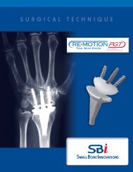
<strong>RE</strong>-MOTION Total Wrist Implant System<br />
<strong>Surgical</strong> <strong>Technique</strong><br />
CONTENTS<br />
Introduction<br />
re-MOTION Design Rationale 1<br />
Precise Guidance Technology Design Rationale 2<br />
Pros<strong>the</strong>sis Design 3<br />
Preoperative Assessment 4<br />
<strong>Surgical</strong> Procedure<br />
1. Exposure 5<br />
2. Carpal Resection 6<br />
3. Radial Preparation 8<br />
4. Carpal Preparation 11<br />
5. Implant Placement 14<br />
6. Closure 16<br />
Follow Up 16<br />
Technical Tips 17<br />
Indications, Contraindications, Warnings,<br />
Precautions, & Patient Counseling Information 17<br />
Acknowledgement<br />
<strong>Small</strong> <strong>Bone</strong> Innovations, Inc. would like to acknowledge a designer of <strong>the</strong> <strong>RE</strong>-MOTION Total Wrist System; Amit Gupta, MD,<br />
University of Louisville, Louisville Kentucky. Dr. Gupta is a leader in <strong>the</strong> field of total wrist arthroplasty. He is dedicated to <strong>the</strong><br />
advancement of small bone and joint surgery in order to provide better clinical outcomes for his patients.
<strong>RE</strong>-MOTION Design Rationale<br />
The <strong>RE</strong>-MOTION Total Wrist Implant is a pros<strong>the</strong>sis anatomically<br />
designed for minimal resection of <strong>the</strong> distal radius<br />
and carpal bones of <strong>the</strong> wrist. The implant is provided in<br />
left and right hand configurations with geometrically scaled<br />
sizes that approximate <strong>the</strong> anthropomorphic sizes of different<br />
radio-carpal joints. The pros<strong>the</strong>sis is composed of three<br />
primary articulating components; <strong>the</strong> radial, carpal ball, and<br />
carpal plate.<br />
The radial component is designed much like a surface<br />
replacement arthroplasty (SRA) in that it seats against <strong>the</strong><br />
scaphoid and lunate fossa and preserves <strong>the</strong> peripheral rim<br />
of <strong>the</strong> distal radius with its important ligamentous and soft<br />
tissue attachments. The configuration requires minimal resection<br />
of <strong>the</strong> distal radius and preserves <strong>the</strong> sigmoid notch and<br />
articulation with <strong>the</strong> head of <strong>the</strong> distal ulna.<br />
The carpal plate component is a low profile design that<br />
minimizes <strong>the</strong> amount of bone resection and does not<br />
interfere with <strong>the</strong> normal function of <strong>the</strong> wrist extensor<br />
tendons. The carpal plate has a central stem for insertion into<br />
<strong>the</strong> capitate and accommodates two carpal screws for fixation<br />
to <strong>the</strong> scaphoid and hamate within <strong>the</strong> distal carpal row.<br />
The carpal ball component acts as an intercalated segment<br />
that articulates with both <strong>the</strong> radial and carpal plate<br />
components. The primary articulation occurs with <strong>the</strong> radial<br />
component. This articulation is ellipsoidal and acts along two<br />
perpendicular axes of rotation, similar to a universal joint,<br />
which lie in coronal and sagittal planes where by permitting<br />
motions of flexion-extension and radio-ulnar deviation<br />
respectively. The convexity of <strong>the</strong> radial component’s articular<br />
geometry resists ulno-volarly directed forces that can cause<br />
excessive wear and implant subluxation.<br />
The secondary articulation of <strong>the</strong> carpal ball occurs with <strong>the</strong><br />
carpal plate component. This articulation is rotational about<br />
an axis aligned with <strong>the</strong> longitudinal axis of <strong>the</strong> third metacarpal.<br />
This additional degree of freedom diverts rotational forces<br />
from <strong>the</strong> bone implant interface that can cause loosening and<br />
may lead to implant failure. The additional laxity also provides<br />
compensation for potential misalignment of <strong>the</strong> device due to<br />
advanced deformity caused by rheumatoid or degenerative<br />
arthritis.<br />
1
Precise Guidance Technology <br />
Design Rationale<br />
The wrist is one of <strong>the</strong> more complex joints in <strong>the</strong> human<br />
body. For this reason, it is one of <strong>the</strong> more difficult joints to<br />
reconstruct. Precise Guidance Technology (PGT )<br />
Instrumentation was designed to produce consistent surgical<br />
outcomes by offering surgeons a predictable and reproducible<br />
approach to total wrist arthroplasty. PGT is an intuitive,<br />
step-by-step approach to wrist replacement that provides<br />
precise guidance when needed, while, leaving <strong>the</strong> freedom to<br />
adequately perform <strong>the</strong> procedure in <strong>the</strong> hands of <strong>the</strong> surgeon.<br />
The <strong>RE</strong>-MOTION Total Wrist Implant has demonstrated years of<br />
successful clinical outcomes. This implant design utilizes<br />
<strong>the</strong> Surface Replacement concept, which requires minimal<br />
bone resection and preserves <strong>the</strong> soft tissue and ligamentous<br />
structures that provide natural stability to <strong>the</strong> wrist. The<br />
PGT instruments provide specifically designed outriggers and<br />
guides that orient from consistent anatomical landmarks,<br />
offering <strong>the</strong> surgeon control over preparation and implant<br />
placement.<br />
PGT is a modular instrument system that originates with <strong>the</strong><br />
placement of <strong>the</strong> PGT Guide. Once this guide is mounted<br />
successfully on <strong>the</strong> dorsum of <strong>the</strong> radius, <strong>the</strong> rest of <strong>the</strong><br />
procedure is accomplished by attaching cutting guides and<br />
temples to <strong>the</strong> PGT Guide. Because <strong>the</strong>se instruments use a<br />
common reference, <strong>the</strong> radial and carpal preparations remain<br />
in constant alignment.<br />
Throughout <strong>the</strong> procedure, <strong>the</strong> surgeon is guided from one<br />
step to <strong>the</strong> next, mitigating <strong>the</strong> complications associated with<br />
treating complex disorders of <strong>the</strong> wrist. To obtain a successful<br />
outcome, it is important to assure proper orientation of <strong>the</strong><br />
radial and carpal components and to preserve stabilizing<br />
structures. The PGT approach to total wrist arthroplasty<br />
eliminates <strong>the</strong> majority of <strong>the</strong>se challenges.<br />
The PGT Instrumentation coupled with an advanced technique<br />
produces consistent surgical outcomes by offering surgeons<br />
a predictable and reproducible approach to total wrist<br />
arthroplasty.<br />
2<br />
<strong>RE</strong>-MOTION Total Wrist Implant System <strong>Surgical</strong> <strong>Technique</strong>
Pros<strong>the</strong>sis Design<br />
Proximal Radial Component<br />
The radial component is fabricated from cobalt chromemolybdenum<br />
alloy. The intra-medullary stem is coated with<br />
commercially pure titanium plasma coating to promote<br />
osseointegration. The distal surface is contoured to approximate<br />
<strong>the</strong> volar tilt and ulnar inclination angles of <strong>the</strong> distal radius. The<br />
articular surface is precision machined and highly polished for<br />
articulation with <strong>the</strong> carpal ball component.<br />
Carpal Ball Component<br />
The carpal ball component is fabricated from ultra-high molecular<br />
weight polyethylene (UHMWPe) material. The proximal articular<br />
surface is elliptical to maximize <strong>the</strong> surface contact with <strong>the</strong> radial<br />
component over a full range of flexion-extension and radio-ulnar<br />
deviation. The carpal ball is fastened to <strong>the</strong> carpal plate using a snap<br />
fit “ball and socket” configuration allowing for limited axial rotation to<br />
occur along <strong>the</strong> long axis of <strong>the</strong> third metacarpal. The distal articular<br />
surface of <strong>the</strong> carpal ball has two slotted openings that accommodate<br />
<strong>the</strong> carpal screws.<br />
Carpal Plate Component<br />
The carpal plate component is fabricated from cobalt chromemolybdenum<br />
alloy. The buttress surface and intramedullary stem are<br />
coated with commercially pure titanium plasma coating to promote<br />
osseointegration. The stem is dorsally offset from <strong>the</strong> carpal screw<br />
hole locations to accommodate <strong>the</strong> arch of <strong>the</strong> carpus. The articular<br />
surface and spherical ball are precision machined and highly polished<br />
to allow for articulation with <strong>the</strong> carpal ball component.<br />
Carpal Screw Component<br />
The carpal screw component is fabricated from cobalt chromemolybdenum<br />
alloy. The screws are provided in five (5) different<br />
lengths and have a cancellous thread form for optimum<br />
fixation with <strong>the</strong> carpal bones of <strong>the</strong> wrist. The spherical head allows<br />
for ideal screw angulation that is determined during <strong>the</strong> surgical<br />
procedure. The hex drive feature on <strong>the</strong> carpal screw component<br />
accepts a standard 2.5mm screw driver.<br />
3
Preoperative Assessment<br />
Preoperative assessment consists of true A/P and Lateral x-rays<br />
of <strong>the</strong> wrist. The degree of carpal collapse and subluxation /<br />
dislocation of <strong>the</strong> carpus on <strong>the</strong> distal radius must be assessed<br />
for proper intra-operative planning.<br />
A template overlay is used to determine <strong>the</strong> appropriate size<br />
wrist implant. Minimal resection of <strong>the</strong> distal radius should<br />
be combined with resection of <strong>the</strong> proximal carpal rows and<br />
proximal head of <strong>the</strong> capitate and hamate. With <strong>the</strong> template<br />
overlay, <strong>the</strong> distal component should provide insertion within<br />
<strong>the</strong> capitate, hamate and distal scaphoid. Avoid <strong>the</strong> central<br />
peg or radial and ulnar screws entering into <strong>the</strong> metacarpals or<br />
across <strong>the</strong> carpometacarpal joints.<br />
From lateral x-rays (or wrist tomograms), volar subluxation of<br />
<strong>the</strong> carpus can be estimated and correction planned for by<br />
limited resection of <strong>the</strong> distal radius (to a perpendicular<br />
surface) and correct pros<strong>the</strong>tic alignment and placement.<br />
In patients with excessive carpal bone resorption, <strong>the</strong> distal<br />
component fixation (screw fixation) may need to cross <strong>the</strong><br />
carpo-metacarpal joints. A template overlayed on <strong>the</strong> wrist<br />
will assist in noting this variation in <strong>the</strong> surgical technique.<br />
<strong>Bone</strong> cement fixation or impaction grafting may be required<br />
to achieve firm distal implant fixation. In addition, bone grafting<br />
of <strong>the</strong> distal carpal row may be indicated to provide an<br />
“autofusion” for improved distal component fixation.<br />
Rheumatoid Diseased Wrist<br />
In patients with volar subluxation of <strong>the</strong> wrist, a resurfacing<br />
implant may be contra-indicated. Resection of <strong>the</strong> distal<br />
radius to provide sufficient carpal length for implant insertion<br />
may affect <strong>the</strong> principle of a resurfacing implant as soft tissue<br />
capsule constraints may be compromised. Wrist fusion may<br />
be preferred in patients with advanced synovitis of <strong>the</strong> wrist<br />
resulting in carpal subluxation, excessive ulnar translation and<br />
destruction of both proximal and distal carpal rows.<br />
4<br />
<strong>RE</strong>-MOTION Total Wrist Implant System <strong>Surgical</strong> <strong>Technique</strong>
<strong>RE</strong>-MOTION Total Wrist Implant System <strong>Surgical</strong> <strong>Technique</strong><br />
surgical procedure<br />
figure 1A<br />
1<br />
Exposure<br />
A dorsal incision is made in line with <strong>the</strong> third metacarpal<br />
and centered directly over Lister’s Tubercle. Skin<br />
flaps are elevated protected cutaneous nerves<br />
(figure 1A).<br />
The extensor retinaculum is exposed and reflected from<br />
radial to ulna, from <strong>the</strong> first extensor compartment to<br />
<strong>the</strong> fifth or sixth extensor compartment. This reflection<br />
of <strong>the</strong> extensor retinaculum (ra<strong>the</strong>r than a central<br />
division) is recommended so that <strong>the</strong> distal 1/3 can<br />
be used to reinforce <strong>the</strong> dorsal joint capsule if<br />
necessary (Figure 1B).<br />
figure 1B<br />
After exposure, a synovectomy of <strong>the</strong> extensor tendons<br />
is performed as required (figure 1C).<br />
figure 1C<br />
5
A rectangular shaped wrist flap is reflected from<br />
proximal to distal to expose <strong>the</strong> proximal and distal carpal<br />
rows. The dorsal wrist flap should be divided close<br />
to <strong>the</strong> dorsal rim of <strong>the</strong> distal radius but with <strong>the</strong> proximal<br />
tissue preserved for capsule closure repair. (Figure<br />
1D).<br />
figure 1D<br />
If insufficient capsule is anticipated, <strong>the</strong> extensor<br />
retinaculum should be preserved by a radial to ulnar<br />
reflection of <strong>the</strong> extensor retinaculum. The distal third<br />
of <strong>the</strong> retinaculum can <strong>the</strong>n be used to augment <strong>the</strong><br />
dorsal capsule repair.<br />
If <strong>the</strong>re is palmar subluxation of <strong>the</strong> carpus, or o<strong>the</strong>rwise<br />
tight radio-carpal space, soft tissue release may be<br />
required to bring <strong>the</strong> carpus out to length. When<br />
complete release of <strong>the</strong> volar capsule is required to<br />
reduce <strong>the</strong> carpus, post-operative instability may occur.<br />
Surgeon judgment related to potential instability is<br />
required.<br />
Note: A longitudinal incision is recommended.<br />
Preservation of <strong>the</strong> capsule on <strong>the</strong> dorsal rim of <strong>the</strong><br />
distal radius is recommended.<br />
2<br />
Carpal Resection<br />
Assemble <strong>the</strong> Lunate tab and mount <strong>the</strong> Assembly onto<br />
<strong>the</strong> PGT Guide (figure 2A).<br />
figure 2A<br />
Place <strong>the</strong> wrist in flexion with slight distraction. Insert<br />
<strong>the</strong> Lunate Tab from dorsal to volar into <strong>the</strong> radio-carpal<br />
joint in an rolling method, for ease of insertion. Position<br />
<strong>the</strong> Lunate Tab against <strong>the</strong> lunate fossa (figure 2B).<br />
figure 2B<br />
6<br />
<strong>RE</strong>-MOTION Total Wrist Implant System <strong>Surgical</strong> <strong>Technique</strong>
Correct positioning of <strong>the</strong> PGT Guide is critical to <strong>the</strong><br />
procedure. The PGT Guide should be located over<br />
Lister’s tubercle and rest firmly on <strong>the</strong> dorsal surface of<br />
<strong>the</strong> distal radius. The distal end of <strong>the</strong> PGT Guide on <strong>the</strong><br />
lateral x-ray should align with <strong>the</strong> articulating surface of<br />
<strong>the</strong> lunate fossa of <strong>the</strong> distal radius.<br />
figure 2D<br />
Secure <strong>the</strong> PGT Guide to <strong>the</strong> dorsal aspect of <strong>the</strong> distal<br />
radius with 2.0mm, non-threaded K-wires. Confirm<br />
position of <strong>the</strong> PGT Guide with x-ray imaging. A radiopague<br />
rod runs down <strong>the</strong> middle of <strong>the</strong> PGT Guide<br />
Handle. This rod should appear parallel to <strong>the</strong> long axis<br />
of <strong>the</strong> radius on both, <strong>the</strong> A/P and Lateral x-rays. Once<br />
satisfactory positioning of <strong>the</strong> PGT Guide is achieved,<br />
remove <strong>the</strong> PGT Tab (figure 2D).<br />
Note: Radiopague marker within PGT guide handle<br />
must be parallel to <strong>the</strong> radius on <strong>the</strong> A/P and Lateral<br />
x-ray.<br />
Insert <strong>the</strong> PGT Carpal Cutting Guide into <strong>the</strong> PGT<br />
Guide and tighten in place. The position of <strong>the</strong> Carpal<br />
Cutting Guide should be established based upon a<br />
pre-operative assessment using an x-ray template. The<br />
proximal shaft of <strong>the</strong> Carpal Cutting Guide is equipped<br />
with sizing graduation markers. These markers<br />
correspond to <strong>the</strong> small, medium, and large sized<br />
implants (figure 2E).<br />
figure 2E<br />
7
Place <strong>the</strong> Carpal Cutting Guide across <strong>the</strong> wrist and<br />
align with <strong>the</strong> 3rd metacarpal. Typically,<strong>the</strong> lunate,<br />
triquetrum, proximal scaphoid, head of <strong>the</strong> capitate,<br />
and head of <strong>the</strong> hamate are resected. If <strong>the</strong> Carpal<br />
Cutting Guide is placed correctly, <strong>the</strong> cut should be<br />
perpendicular to <strong>the</strong> long axis of <strong>the</strong> forearm. Resect<br />
<strong>the</strong> carpal bones with an oscillating saw (figure 2F).<br />
figure 2F<br />
Generally, 1 to 2 millimeters of <strong>the</strong> head of <strong>the</strong> capitate<br />
is resected. In patients with excessive carpal erosion or<br />
advanced DJD, a more distally based resection may be<br />
required. Generally, in <strong>the</strong>se cases removal of all bone<br />
proximally is recommended, with preservation of <strong>the</strong><br />
volar wrist capsule.<br />
Once <strong>the</strong> carpal resection is complete, remove <strong>the</strong><br />
Carpal Cutting Guide from <strong>the</strong> PGT Guide.<br />
Note: It may be helpful, prior to resection, to use<br />
transverse K-wires to stabilize <strong>the</strong> distal scaphoid to<br />
<strong>the</strong> carpus.<br />
3<br />
Radial Preparation<br />
Insert <strong>the</strong> PGT Radial Resurfacing Guide into <strong>the</strong> PGT<br />
Guide. Tighten at <strong>the</strong> proper height to adequately<br />
contour <strong>the</strong> scaphoid and lunate fossae. The<br />
Resurfacing Guide is equipped with reference line<br />
markers to facilitate adjustment of <strong>the</strong> guide during<br />
burring. The reference lines are in two millimeter<br />
increments (figure 3A).<br />
figure 3A<br />
The lateral profile of <strong>the</strong> Burr should be centered about<br />
<strong>the</strong> distal radius. Tighten <strong>the</strong> set screw in <strong>the</strong> Burr Collar<br />
when adequate positioning is achieved. The PGT Radial<br />
Burr should remove excess bone on <strong>the</strong> radial styloid<br />
and central ridge between <strong>the</strong> scaphoid and lunate<br />
fossae. Care should be taken not to resect subchondral<br />
bone. A smooth surface that matches <strong>the</strong> contour of<br />
<strong>the</strong> radial pros<strong>the</strong>sis proximal surface should result.<br />
Remove <strong>the</strong> Radial Resurfacing Guide (figure 3B).<br />
Note: Surgeons may have better control of <strong>the</strong> burr if a<br />
pulling motion is used instead of a pushing motion.<br />
figure 3B<br />
8<br />
<strong>RE</strong>-MOTION Total Wrist Implant System <strong>Surgical</strong> <strong>Technique</strong>
Insert <strong>the</strong> PGT Radial Pilot Template into <strong>the</strong> PGT Guide.<br />
(figure 3C). The Radial Pilot Template should sit firmly<br />
against <strong>the</strong> prepared surface of <strong>the</strong> distal radius and 2 to<br />
3 millimeters below <strong>the</strong> dorsal cortex of <strong>the</strong> radius. The<br />
Radial Pilot Template may be adjusted dorsal and<br />
palmar to achieve correct optimal alignment<br />
(figure 3D).<br />
figure 3C<br />
figure 3D<br />
Place <strong>the</strong> 2mm threaded guide pin into <strong>the</strong> distal radius<br />
and advance 4 to 5 centimeters until secure in <strong>the</strong> bone.<br />
The guide pin should be centered down <strong>the</strong> diaphysis of<br />
<strong>the</strong> distal radius. Confirm <strong>the</strong> position of <strong>the</strong> guide pin<br />
on A/P and Lateral x-ray (figure 3E).<br />
figure 3E<br />
Once correct positioning of <strong>the</strong> guide pin is achieved,<br />
remove <strong>the</strong> Pilot Template distally by sliding it off <strong>the</strong><br />
guide pin. Remove <strong>the</strong> PGT Guide by lifting it dorsally<br />
(figure 3F).<br />
figure 3F<br />
9
The cannulated PGT Radial Counterbore Drill is used to<br />
create a pilot hole for broaching (figure 3G).<br />
figure 3G<br />
Broach <strong>the</strong> distal radius over <strong>the</strong> guide pin. Based upon<br />
<strong>the</strong> preoperative assessment of <strong>the</strong> implant size, <strong>the</strong><br />
distal radius is broached with increasing sized broaches<br />
to allow full seating of <strong>the</strong> radial component<br />
(Figure 3H).<br />
figure 3H<br />
Note: Take care not to over-broach or re-set <strong>the</strong><br />
direction of <strong>the</strong> broach because a press-fit application<br />
of <strong>the</strong> radial component is <strong>the</strong> goal.<br />
Care should be taken to make sure <strong>the</strong> angle of <strong>the</strong><br />
broach is aligned with <strong>the</strong> long axis of <strong>the</strong> radius. The<br />
flat portion of <strong>the</strong> broach handle should always be<br />
parallel to <strong>the</strong> dorsum of <strong>the</strong> radius. The broach may<br />
need to be withdrawn to clean <strong>the</strong> teeth and clear <strong>the</strong><br />
intramedullary cavity of debris. Burring may be needed<br />
in <strong>the</strong> radial styloid region to prevent ulnar migration<br />
of <strong>the</strong> broach during impaction (figure 3I).<br />
figure 3I<br />
10 <strong>RE</strong>-MOTION Total Wrist Implant System <strong>Surgical</strong> <strong>Technique</strong>
Insert <strong>the</strong> radial trial into <strong>the</strong> prepared canal, and impact<br />
<strong>the</strong> trial until seated. Evaluate <strong>the</strong> fit of <strong>the</strong> component<br />
against <strong>the</strong> scaphoid and lunate fossae as well as <strong>the</strong><br />
dorsal peripheral ridge. The implant should fit flush with<br />
or below <strong>the</strong> dorsal ridge of <strong>the</strong> distal radius. If <strong>the</strong> fit is<br />
satisfactory, remove <strong>the</strong> trial component by engaging<br />
<strong>the</strong> extraction holes with a towel clamp or equivalent<br />
instrument. If <strong>the</strong> trial is proud, fur<strong>the</strong>r broaching or<br />
selective burring of <strong>the</strong> distal radius may be needed.<br />
However, subchondral bone should always be preserved<br />
(Figure 3J).<br />
figure 3J<br />
4<br />
Carpal Preparation<br />
Position <strong>the</strong> PGT Carpal Template so it rests firmly on<br />
<strong>the</strong> dorsal aspect of <strong>the</strong> capitate and is aligned along<br />
<strong>the</strong> 3rd metacarpal. The dorsal aspect of <strong>the</strong> template<br />
should be flush with <strong>the</strong> dorsal surface of <strong>the</strong> capitate<br />
(figure 4A).<br />
figure 4A<br />
Drill a 2.0 mm K-wire into <strong>the</strong> capitate. Advance <strong>the</strong><br />
K-wire to <strong>the</strong> distal end of <strong>the</strong> capitate. Confirm <strong>the</strong><br />
position of <strong>the</strong> K-wire with imaging (figure 4B).<br />
figure 4B<br />
11
Trial reduction is accomplished using <strong>the</strong> Carpal<br />
Template by cropping <strong>the</strong> K-wire with <strong>the</strong> Wire Cutters<br />
(figure 4C) and placing <strong>the</strong> Carpal Ball Trial over <strong>the</strong><br />
Carpal Template (figure 4D). Re-insert <strong>the</strong> Radial Trial<br />
and articulate with <strong>the</strong> Carpal Ball Trial. Judge wrist<br />
motion and stability and determine if fur<strong>the</strong>r carpal<br />
bone resection is necessary. For over-resection, an<br />
extended carpal ball trial is available.<br />
Note: Previous distal radius or carpal fracture may alter<br />
radio-carpal alignment. Correct mal-alignment with<br />
soft tissue release. Resection of radial styloid may be<br />
required but o<strong>the</strong>rwise preserve subchondral bone.<br />
Carpal subluxation (volar and ulna) must be correct to<br />
allow carpal alignment with <strong>the</strong> distal radius. Soft<br />
tissue release of volar/ulnar capsule may be required.<br />
figure 4C<br />
figure 4D<br />
Once proper positioning of <strong>the</strong> carpal implant is<br />
achieved, remove <strong>the</strong> Carpal Template and <strong>the</strong> K-wire<br />
(figure 4E).<br />
figure 4E<br />
After removal of <strong>the</strong> Trial & K-Wire, place <strong>the</strong> Carpal<br />
Reamer central over <strong>the</strong> K-Wire insertion point. The<br />
reamer is marked with three lines which correspond to<br />
<strong>the</strong> carpal component sizes; small, medium and large<br />
By using <strong>the</strong> Carpal Reamer to <strong>the</strong> appropriate size will<br />
assist in preparing <strong>the</strong> capitate for broaching.<br />
The Carpal Broach is used to widen <strong>the</strong> canal through<br />
<strong>the</strong> capitate. The broach has 3 lines which correspond<br />
with a small, medium and large size component. Insert<br />
<strong>the</strong> broach fully to <strong>the</strong> appropriate line (figure 4F).<br />
figure 4F<br />
12 <strong>RE</strong>-MOTION Total Wrist Implant System <strong>Surgical</strong> <strong>Technique</strong>
Insert <strong>the</strong> Carpal Trial by placing <strong>the</strong> center stem into<br />
<strong>the</strong> capitate. Use <strong>the</strong> impactor to push or gently tap <strong>the</strong><br />
Trial completely into place. Use imaging to verify that<br />
<strong>the</strong> component is positioned correctly (figure 4G).<br />
figure 4G<br />
Prepare <strong>the</strong> screw pilot holes using <strong>the</strong> PGT Metacarpal<br />
Drill Guide. Align <strong>the</strong> Drill Guide on <strong>the</strong> radial button on<br />
<strong>the</strong> face of <strong>the</strong> Carpal Trial and over <strong>the</strong> 2nd metacarpal.<br />
Drill a k-wire through <strong>the</strong> Carpal Trial into <strong>the</strong> distal<br />
scaphoid, trapezoid on <strong>the</strong> radial side. Repeat <strong>the</strong> same<br />
procedure on <strong>the</strong> ulnar side. Align <strong>the</strong> Drill Guide on<br />
<strong>the</strong> ulna button on <strong>the</strong> face of <strong>the</strong> Carpal Trial and over<br />
<strong>the</strong> 4th metacarpal. Drill a k-wire through <strong>the</strong> length of<br />
<strong>the</strong> hamate. Use imaging to ensure proper preparation.<br />
A “W” should be visible on imaging between <strong>the</strong> two<br />
k-wires and <strong>the</strong> center stem of <strong>the</strong> Trial in <strong>the</strong> capitate<br />
(figure 4H). Once proper positioning is achieved,<br />
remove <strong>the</strong> k-wires and drill into <strong>the</strong> k-wire holes using<br />
a 2mm drill bit in order to enlarge <strong>the</strong> holes enough to<br />
accept <strong>the</strong> 4.5mm bone screws.<br />
figure 4H<br />
Note: Many surgeons prefer to cross <strong>the</strong> second<br />
carpometacarpal joint, but crossing <strong>the</strong> fourth<br />
carpometacarpal joint is not recommended.<br />
13
Prior to implant placement, an additional trial reduction<br />
is recommended. If <strong>the</strong> radial trial was removed during<br />
carpal preparation, reinsert <strong>the</strong> Radial Trial into <strong>the</strong><br />
prepared canal, and impact <strong>the</strong> trial until seated<br />
(figure 4I). Replacing <strong>the</strong> Carpal Ball Trial on to <strong>the</strong><br />
Carpal Trial and articulate <strong>the</strong> Total Wrist for stability<br />
(figure 4J).<br />
figure 4I<br />
Note: Wrist range of motion should be tested to<br />
measure extension (40-50 degrees), flexion (30-35<br />
degrees), and radial/ulnar deviation (40 degrees total).<br />
During trial reduction, no more <strong>the</strong>n 2 to 3 millimeters<br />
of laxity should be present with dorsal-palmar<br />
displacement of <strong>the</strong> wrist. A Plus Carpal Ball, which<br />
provides 1 millimeter of additional thickness, can be<br />
used if necessary.<br />
figure 4J<br />
5<br />
Implant Placement<br />
Insert <strong>the</strong> radial implant and press fit in place. Using<br />
<strong>the</strong> radial impactor, tap <strong>the</strong> implant until fully seated<br />
(figure 5A).<br />
Note: To determine implant fit, gentle traction on <strong>the</strong><br />
radial component should be performed. If <strong>the</strong> radial<br />
component is loose, impaction grafting of cancellous<br />
bone is recommended. For osteoporotic patients,<br />
consider bone cement. Insert <strong>the</strong> radial component<br />
and tap firmly into place.<br />
figure 5A<br />
Insert carpal component and press fit. It is aligned with<br />
<strong>the</strong> centering hole in <strong>the</strong> capitate and pushed or tapped<br />
into place (figure 5B).<br />
Accurately measure <strong>the</strong> required radial and ulna screw<br />
lengths with a depth gauge.<br />
figure 5B<br />
14 <strong>RE</strong>-MOTION Total Wrist Implant System <strong>Surgical</strong> <strong>Technique</strong>
The self tapping screws are inserted through <strong>the</strong> carpal<br />
plate and into <strong>the</strong> holes created by <strong>the</strong> 2mm drill bit<br />
with a 2.5 mm hex driver. Use imaging to determine<br />
that <strong>the</strong> screws are <strong>the</strong> correct length. The screws are<br />
<strong>the</strong>n tightened into place (figure 5C).<br />
figure 5C<br />
Note: The screws may cross <strong>the</strong> 2nd carpometacarpal<br />
joint but crossing <strong>the</strong> 4th carpometacarpal joint is not<br />
recommended.<br />
The polyethylene carpal ball is now placed onto <strong>the</strong><br />
distal component and snapped into place using <strong>the</strong> carpal<br />
ball impactor (figure 5D).<br />
Note: Removal of <strong>the</strong> carpal ball may be necessary to<br />
adjust joint tension or laxity or to modify screw length.<br />
If <strong>the</strong> carpal ball needs to be removed, care must be<br />
taken to not damage <strong>the</strong> polished surface of <strong>the</strong> carpal<br />
component. This can be accomplished by drilling<br />
a small hole in <strong>the</strong> radial and ulnar tips of <strong>the</strong><br />
polyethylene. Engage <strong>the</strong> holes with bone reduction<br />
forceps and pry in a radial or ulnar direction to<br />
disengage <strong>the</strong> snap fit assembly.<br />
figure 5D<br />
The total wrist joint is articulated and stability assessed.<br />
An extra length polyethylene ball may be indicated if<br />
<strong>the</strong>re is residual dorsal-palmar laxity or instability.<br />
15
6 Closure<br />
Assess range of motion through radio-ulnar deviation<br />
and flexion-extension of <strong>the</strong> wrist. If range of motion is<br />
satisfactory and <strong>the</strong>re is good stability and no<br />
impingement, proceed with wound closure. Repair <strong>the</strong><br />
dorsal capsule back to <strong>the</strong> soft tissue on <strong>the</strong> distal edge<br />
of <strong>the</strong> distal radius. If <strong>the</strong> capsule is thin at this area,<br />
reinforce <strong>the</strong> capsule with <strong>the</strong> distal half of <strong>the</strong> extensor<br />
retinaculum with non resorbable 2-0 or 3-0 sutures.<br />
Repair <strong>the</strong> proximal portion of <strong>the</strong> extensor retinaculum<br />
over <strong>the</strong> extensor tendons in <strong>the</strong> usual fashion, without<br />
including <strong>the</strong> extensor pollicis longus tendon which can<br />
be left extra-retinacular to prevent tendon irritation or<br />
rupture (FIGU<strong>RE</strong>S 6A & 6B).<br />
figure 6A<br />
Follow Up<br />
After wound closure, <strong>the</strong> wrist is immobilized in extension of<br />
25-30° and neutral radioulnar deviation with plaster support.<br />
The surgical drain is removed at 24-48 hours, and at this time<br />
a short arm cast is applied with inclusion of <strong>the</strong> base of <strong>the</strong><br />
thumb. The cast is worn for 2 weeks. At that time (2 weeks),<br />
sutures are removed and physio<strong>the</strong>rapy of <strong>the</strong> wrist with<br />
assisted range of motion started.<br />
Continued support splinting for up to six weeks is<br />
recommended to allow for full bone ingrowth of <strong>the</strong> proximal<br />
and distal components. Cast or splint support for 8 weeks<br />
should be considered if <strong>the</strong>re is osteoporotic or o<strong>the</strong>rwise<br />
poor bone stock. Streng<strong>the</strong>ning of <strong>the</strong> wrist can begin around<br />
4-6 weeks with hand grippers and resisted weights. Resisted<br />
weights should not be used until a minimum of 8 weeks<br />
after surgery.<br />
figure 6B<br />
The range of motion goal is 40° of extension, flexion, and 40°<br />
total radioulnar deviation. Studies have shown that this range<br />
of motion is sufficient for 80% of activities of daily living (ADLs)1.<br />
In patients with “wet” synovitic-type rheumatoid<br />
arthritis, a longer period of cast immobilization prior to starting<br />
motion may be justified. Similarly, in post-traumatic arthritic<br />
conditions wherein stiffness of <strong>the</strong> wrist is a concern, earlier<br />
wrist motion may be justified.<br />
Radiographic assessment of <strong>the</strong> total wrist should be at 6 weeks,<br />
3 months, 6 months, and 1 year. Long-term assessment should<br />
be considered at 2 years, 5 and 10 years.<br />
Cautions<br />
• Antibiotics are recommended pre-procedure for all patients<br />
requiring dental, urologic, colonoscopy, or o<strong>the</strong>r invasive<br />
body cavity procedures.<br />
• Sports such as golf, tennis, and bowling are restricted. There<br />
is no clinical data to know <strong>the</strong> effect of sports activities on<br />
total wrist replacement patients.<br />
• Similarly, use of <strong>the</strong> wrist in heavy duty work requiring heavy<br />
lifting over 20 pounds is discouraged related to <strong>the</strong> adverse<br />
mechanical effect of weight lifting on <strong>the</strong> wrist.<br />
16 <strong>RE</strong>-MOTION Total Wrist Implant System <strong>Surgical</strong> <strong>Technique</strong>
Technical Tips<br />
1. Use imaging with each step of <strong>the</strong> procedure.<br />
2. Proper placement of <strong>the</strong> PGT Guide is extremely important<br />
prior to proceeding with burring or broaching of distal radius.<br />
3. Use of <strong>the</strong> Burr to smooth <strong>the</strong> distal radius articular surface<br />
can be helpful with radial pros<strong>the</strong>sis setting, but avoid<br />
removal of subchondral bone.<br />
4. Avoid dorsal/palmar tilt of <strong>the</strong> distal radius.<br />
5. Carpal component alignment with <strong>the</strong> capitate is key.<br />
Consider K-wire fixation and/or fusion of <strong>the</strong> distal carpal<br />
row to enhance distal component fixation.<br />
Soft tissue capsule repair to distal radius is straight forward. If<br />
capsule is thin, use distal third of retinaculum to reinforce.<br />
Indications<br />
Recommended clinical situations for potential use of this device are as follows:<br />
• Rheumatoid arthritis in which preservation of wrist motion is <strong>the</strong> goal. The total<br />
wrist replacement may be performed alone, or in association with resection of<br />
<strong>the</strong> distal ulna or distal ulna (uHead) pros<strong>the</strong>tic replacement.<br />
• Degenerative arthritis (osteoarthritis) of <strong>the</strong> wrist. This is a less common type of<br />
wrist arthritis, but can occur across both <strong>the</strong> radial carpal and midcarpal joints.<br />
• Post-traumatic arthritis of <strong>the</strong> wrist. This can result from failed treatment of<br />
scaphoid fractures, scapho lunate dissociation, Kienbock’s Disease, or fracturedislocations<br />
of <strong>the</strong> wrist. It may also follow intra-articular fractures of <strong>the</strong> distal<br />
radius. Total wrist replacement may also be indicated in failed intercarpal<br />
fusions and proximal row carpectomy.<br />
The low profile of <strong>the</strong> <strong>RE</strong>-MOTION Total Wrist provides less bone resection than<br />
o<strong>the</strong>r total wrist replacements, providing <strong>the</strong> total wrist option for osteoarthritis<br />
and post-traumatic arthritis.<br />
ContraIndications<br />
Clinical situations where <strong>the</strong> use of this device should be avoided are as follows:<br />
• Previous infection of <strong>the</strong> wrist is an absolute contra-indication for pros<strong>the</strong>tic<br />
replacement.<br />
• Wet (synovitis related) rheumatoid arthritis is a relative contra-indication since<br />
post operative wrist ligament laxity may lead to instability.<br />
• Previous wrist fusion (partial or complete) and failed silicone implants are<br />
relative contra-indications unless wrist extensor tendon function can be<br />
restored and joint capsule ligament constraints re-established. There is little<br />
clinical experience with total wrist replacement with previous wrist fusion or<br />
previous pros<strong>the</strong>tic replacement (silicone or metal-poly).<br />
• Carpal subluxation (if excessive) is also a contra-indication, especially if volar<br />
capsule release is required to restore carpal length in order to insert <strong>the</strong> pros<strong>the</strong>sis.<br />
warnings<br />
Strenuous loading, excessive mobility, and articular instability all may lead to<br />
accelerated wear and eventual failure by loosening, fracture, or dislocation of <strong>the</strong><br />
device. Patients should be made aware of <strong>the</strong> increased potential for device failure<br />
if excessive demands are made upon it.<br />
Notification in accordance with <strong>the</strong> California Safe Drinking Water and Toxic<br />
Enforcement Act of 1986 (Proposition 65): This product contains a chemical(s)<br />
known to <strong>the</strong> State of California to cause cancer, and/or birth defects and o<strong>the</strong>r<br />
reproductive toxicity.<br />
precautions<br />
The implant is provided sterile in an undamaged package. If ei<strong>the</strong>r <strong>the</strong> implant or<br />
<strong>the</strong> package appears damaged, expiration date has been exceeded, or if sterility<br />
is questioned for any reason, <strong>the</strong> implant should not be used. Do not re-sterilize.<br />
Meticulous preparation of <strong>the</strong> implant site and selection of <strong>the</strong> proper size<br />
implant increases <strong>the</strong> potential for a successful outcome. The implant should be<br />
removed from its sterile package only after <strong>the</strong> implant site has been prepared and<br />
properly sized. Implants should be handled with blunt instruments to avoid<br />
scratching, cutting or nicking <strong>the</strong> device so as not to adversely affect <strong>the</strong> implant<br />
performance. Polished bearing and articulating surfaces must not come in contact<br />
with hard or abrasive surfaces.<br />
patient counseling information<br />
In addition to <strong>the</strong> patient related information contained in <strong>the</strong> Warnings and<br />
Adverse Events sections, <strong>the</strong> following information should be conveyed to <strong>the</strong><br />
patient:<br />
While <strong>the</strong> expected life of total joint replacement components is difficult to<br />
estimate, it is finite. These components are made of foreign materials which are<br />
placed within <strong>the</strong> body for <strong>the</strong> potential restoration of mobility or reduction of<br />
pain. However, due to <strong>the</strong> many biological, mechanical and physiochemical factors<br />
which affect <strong>the</strong>se devices, <strong>the</strong> components cannot be expected to withstand<br />
<strong>the</strong> activity level and loads of normal healthy bone for an unlimited period of time.<br />
Adverse effects may necessitate reoperation, revision, or fusion of <strong>the</strong> involved<br />
joint.<br />
Please refer to implant package insert for additional product information<br />
including precautions and warnings.<br />
Proper surgical procedures and techniques are necessarily <strong>the</strong> responsibility of<br />
<strong>the</strong> medical professional. Each surgeon must evaluate <strong>the</strong> appropriateness of <strong>the</strong><br />
surgical technique used based on personal medical training and experience.<br />
The contents of this document are protected from unauthorized reproduction or<br />
duplication under U.S. federal law. Permission to reproduce this document (for<br />
educational/instructional use only) may be obtained by contacting <strong>Small</strong> <strong>Bone</strong><br />
Innovations, Inc.<br />
17
<strong>Small</strong> <strong>Bone</strong> Innovations, Inc.<br />
SBi Customer Service: (800) 778-8837<br />
1380 South Pennsylvania Ave.<br />
Morrisville, PA 19067<br />
Fax (866) SBi-0002<br />
Technical Support: (866) SBi-TIPS<br />
<strong>Small</strong> <strong>Bone</strong> Innovations International<br />
ZA Les Bruyères - BP 28<br />
01960 Péronnas, France<br />
Tel: +33 (0) 474 21 58 19<br />
Fax: +33 (0) 474 21 43 12<br />
info@sbi-intl.com<br />
www.totalsmallbone.com<br />
<strong>RE</strong>-MOTION and PGT are trademarks of <strong>Small</strong> <strong>Bone</strong> Innovations, Inc.<br />
7011 3M Copyright ©2013 <strong>Small</strong> <strong>Bone</strong> Innovations, Inc. All rights reserved. MKT 10212 Rev. C 01/13