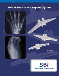
PercuFIX us.qxp - Small Bone Innovations
PercuFIX us.qxp - Small Bone Innovations
PercuFIX us.qxp - Small Bone Innovations

You also want an ePaper? Increase the reach of your titles
YUMPU automatically turns print PDFs into web optimized ePapers that Google loves.
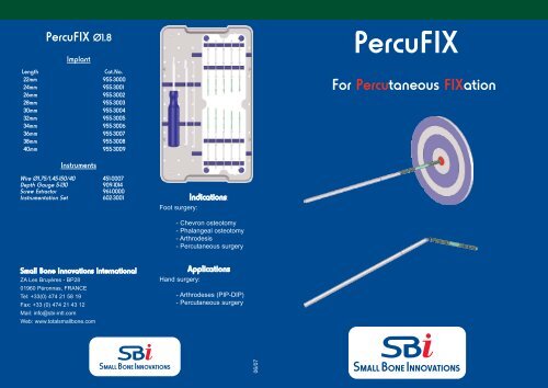
<strong>PercuFIX</strong> Ø1.8<br />
Implant<br />
Length<br />
Cat.No.<br />
22mm 955-3000<br />
24mm 955-3001<br />
26mm 955-3002<br />
28mm 955-3003<br />
30mm 955-3004<br />
32mm 955-3005<br />
34mm 955-3006<br />
36mm 955-3007<br />
38mm 955-3008<br />
40mm 955-3009<br />
<strong>PercuFIX</strong><br />
For Percutaneo<strong>us</strong> FIXation<br />
Instruments<br />
Wire Ø1.75/1.45-150/40 451-0007<br />
Depth Gauge 5-130 909-1014<br />
Screw Extractor 961-0000<br />
Instrumentation Set 602-3001<br />
Indications:<br />
Foot surgery:<br />
- Chevron osteotomy<br />
- Phalangeal osteotomy<br />
- Arthrodesis<br />
- Percutaneo<strong>us</strong> surgery<br />
<strong>Small</strong> <strong>Bone</strong> <strong>Innovations</strong> International<br />
ZA Les Bruyères - BP28<br />
01960 Péronnas, FRANCE<br />
Tel: +33(0) 474 21 58 19<br />
Fax: +33 (0) 474 21 43 12<br />
Mail: info@sbi-intl.com<br />
Web: www.totalsmallbone.com<br />
Applications<br />
Hand surgery:<br />
- Arthrodeses (PIP-DIP)<br />
- Percutaneo<strong>us</strong> surgery<br />
06/07
<strong>PercuFIX</strong> Standard Surgical Technique<br />
<strong>PercuFIX</strong> Surgical Technique for Arthrodesis<br />
1)<br />
2)<br />
A) Direct method<br />
A1) A2)<br />
1) Drill over the two step wires (451-0007)<br />
through both fragments.<br />
3) 4)<br />
2) Measure the screw length with the<br />
direct-reading depth gauge inserted over<br />
the first wire.<br />
A1)Decorticate articular surfaces.<br />
Determine screw length.<br />
A3)<br />
A3) Check for correct positioning and<br />
compression.<br />
A2) Insert <strong>PercuFIX</strong> screw.<br />
A4)<br />
B) To and For method<br />
A4) Break off the shank ONLY if position<br />
and compression are fully satisfactory.<br />
B1) B2)<br />
3) Remove the first wire (the second wire<br />
is left in place to maintain the synthesis of<br />
bone fragments). Drive in the first screw,<br />
taking care to maintain axial alignment.<br />
Advance the screw until the break-off<br />
groove has been reached (color change<br />
point).<br />
5) 6)<br />
4) Measure the second screw length in the<br />
same way.<br />
B1) Decorticate articular surfaces.<br />
Determine screw length.<br />
B3)<br />
B<br />
A<br />
B3) Hold part A to drive the shank (B) into<br />
the distal fragment.<br />
Hold part B and complete retrograde<br />
insertion by reverse screwing.<br />
B2) Perforate the distal bone fragment with<br />
the wire (451-0007).<br />
B4)<br />
B4) Accurately position the two bone<br />
fragments. Drive the screw into the proximal<br />
fragment until the break-off groove reaches<br />
the cortex of the distal fragment.<br />
Check for correct positioning (cf. A3).<br />
Break off shank (cf. A4).<br />
C) Removal<br />
5) Remove the second wire (while the first<br />
screw maintains the synthesis of bone<br />
fragments), and insert the second screw<br />
as previo<strong>us</strong>ly described.<br />
6) Assess fixation before breaking off the<br />
shanks. If fixation is not fully satisfactory,<br />
remove the screws and repeat the<br />
procedure.<br />
C1) C1) Use a small gouge to prepare the entry site for the<br />
screw extractor (961-0000)<br />
-Position the screw extractor in line with the axis of the<br />
screw. If necessary, <strong>us</strong>e image intensification to check for<br />
proper alignment<br />
-Turn counterclockwise so that the extractor engages the<br />
counter threads of the screw over 3 mm and then drives the<br />
screw backward.<br />
WARNING : Disengage the screw from the extractor by<br />
rotating CLOCKWISE : the screw m<strong>us</strong>t be removed prior to<br />
cleaning the instrument.