Design limits and solutions for very large wind turbines
Design limits and solutions for very large wind turbines
Design limits and solutions for very large wind turbines

Create successful ePaper yourself
Turn your PDF publications into a flip-book with our unique Google optimized e-Paper software.
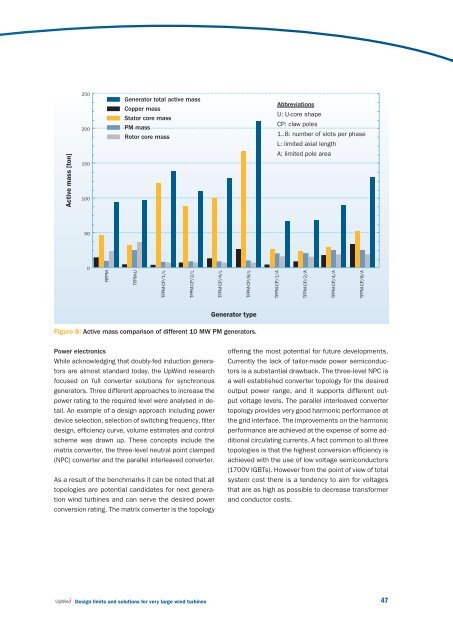
Active mass [ton]<br />
250<br />
200<br />
150<br />
100<br />
Generator total active mass<br />
Copper mass<br />
Stator core mass<br />
PM mass<br />
Rotor core mass<br />
Abbreviations<br />
U: U-core shape<br />
CP: claw poles<br />
1..8: number of slots per phase<br />
L: limited axial length<br />
A: limited pole area<br />
50<br />
0<br />
RFPM<br />
TFPM-U<br />
TFPM-CP/1/L<br />
TFPM-CP/2/L<br />
TFPM-CP/4/L<br />
TFPM-CP/8/L<br />
TFPM-CP/1/A<br />
TFPM-CP/2/A<br />
TFPM-CP/4/A<br />
TFPM-CP/8/A<br />
Generator type<br />
Figure 8: Active mass comparison of different 10 MW PM generators.<br />
Power electronics<br />
While acknowledging that doubly-fed induction generators<br />
are almost st<strong>and</strong>ard today, the UpWind research<br />
focused on full converter <strong>solutions</strong> <strong>for</strong> synchronous<br />
generators. Three different approaches to increase the<br />
power rating to the required level were analysed in detail.<br />
An example of a design approach including power<br />
device selection, selection of switching frequency, filter<br />
design, effi ciency curve, volume estimates <strong>and</strong> control<br />
scheme was drawn up. These concepts include the<br />
matrix converter, the three-level neutral point clamped<br />
(NPC) converter <strong>and</strong> the parallel interleaved converter.<br />
As a result of the benchmarks it can be noted that all<br />
topologies are potential c<strong>and</strong>idates <strong>for</strong> next generation<br />
<strong>wind</strong> <strong>turbines</strong> <strong>and</strong> can serve the desired power<br />
conversion rating. The matrix converter is the topology<br />
offering the most potential <strong>for</strong> future developments.<br />
Currently the lack of tailor-made power semiconductors<br />
is a substantial drawback. The three-level NPC is<br />
a well established converter topology <strong>for</strong> the desired<br />
output power range, <strong>and</strong> it supports different output<br />
voltage levels. The parallel interleaved converter<br />
topology provides <strong>very</strong> good harmonic per<strong>for</strong>mance at<br />
the grid interface. The improvements on the harmonic<br />
per<strong>for</strong>mance are achieved at the expense of some additional<br />
circulating currents. A fact common to all three<br />
topologies is that the highest conversion effi ciency is<br />
achieved with the use of low voltage semiconductors<br />
(1700V IGBTs). However from the point of view of total<br />
system cost there is a tendency to aim <strong>for</strong> voltages<br />
that are as high as possible to decrease trans<strong>for</strong>mer<br />
<strong>and</strong> conductor costs.<br />
<strong>Design</strong> <strong>limits</strong> <strong>and</strong> <strong>solutions</strong> <strong>for</strong> <strong>very</strong> <strong>large</strong> <strong>wind</strong> <strong>turbines</strong><br />
47