hydro thunder - TextFiles.com
hydro thunder - TextFiles.com
hydro thunder - TextFiles.com

You also want an ePaper? Increase the reach of your titles
YUMPU automatically turns print PDFs into web optimized ePapers that Google loves.
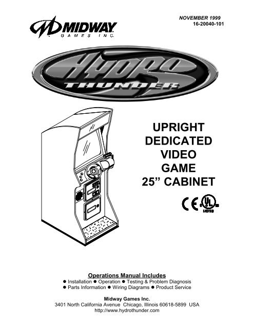
NOVEMBER 1999<br />
16-20044-101 16-20040-101<br />
UPRIGHT<br />
DEDICATED<br />
VIDEO<br />
GAME<br />
25” CABINET<br />
Operations Manual Includes<br />
z Installation z Operation z Testing & Problem Diagnosis<br />
z Parts Information z Wiring Diagrams z Product Service<br />
Midway Games Inc.<br />
3401 North California Avenue Chicago, Illinois 60618-5899 USA<br />
http://www.<strong>hydro</strong><strong>thunder</strong>.<strong>com</strong>
HYDROTHUNDER <br />
C H A P T E R<br />
O N E<br />
PRODUCT SAFETY,<br />
SPECIFICATIONS,<br />
SETUP, & MAINTENANCE<br />
NOTICE: This manual is subject to change without notice. MIDWAY reserves the right to make<br />
improvements in equipment function, design, or <strong>com</strong>ponents as progress in engineering or<br />
manufacturing methods may warrant.<br />
Fill out and mail in the Game Information Card. Include the game serial number from the label<br />
on the rear of the cabinet. For your records, write the game serial number in the manual.<br />
SERIAL NUMBER _______________________________________________________<br />
Setup 1-1
Setup 1-2
SAFETY INSTRUCTIONS<br />
The following safety instructions apply to operators and service personnel. Read these instructions before<br />
preparing the game for play. Other safety instructions appear throughout this manual.<br />
DEFINITIONS OF SAFETY TERMS<br />
DANGER indicates an imminent hazard. If you fail to avoid this hazard, it WILL cause death or serious<br />
injury.<br />
WARNING indicates a potential hazard. If you fail to avoid this hazard, it COULD cause death or serious<br />
injury.<br />
CAUTION indicates a potential hazard. If you fail to avoid this hazard, it MAY cause minor or moderate<br />
injury. CAUTION also alerts you about unsafe practices.<br />
NOTICE indicates information of special importance.<br />
WARNING: TRANSPORTING GAMES. This game contains glass and fragile electronic<br />
devices. Use appropriate care when transporting this game. Avoid rough handling when<br />
moving the cabinet. Do not move this game with the power on.<br />
WARNING: DISCONNECT POWER. Always turn the power OFF and unplug the game<br />
before attempting service or adjustments unless otherwise instructed. Installing or<br />
repairing PC boards with power ON can damage <strong>com</strong>ponents and void the warranty.<br />
WARNING: GROUND GAMES. Avoid electrical shocks! Do not plug in a game until you<br />
have inspected and properly grounded it. Only plug this game into a grounded, threewire<br />
outlet. Do not use a “cheater” plug, or cut off the ground pin on the line cord.<br />
WARNING: AVOID ELECTRICAL SHOCKS. This video game system does not utilize<br />
an isolation transformer. Internal cabinet AC is not isolated from the external AC line.<br />
WARNING: HANDLE FLUORESCENT TUBE AND CRT WITH CARE. If you drop a<br />
fluorescent tube or CRT and it breaks, it will implode! Shattered glass can fly eight feet<br />
or more from the implosion.<br />
CAUTION: CHECK POWER SELECTOR, LAMP. Set the 115/230VAC selector on the<br />
power supply for the correct line voltage. Check the selector setting before switching on<br />
the game. Verify that the fluorescent lamp assembly is correct for the local line voltage.<br />
CAUTION: USE PROPER FUSE. Avoid electrical shock! Replacement fuses must be of<br />
the same type as those they replace. Fuse voltage and current ratings must match<br />
ratings on the original fuse.<br />
CAUTION: ATTACH CONNECTORS PROPERLY. Be sure that printed circuit board<br />
(PCB) connectors mate properly. If connectors do not slip on easily, do not force them. A<br />
reversed connector may damage your game and void the warranty. Connector keys only<br />
allow a connector to fit one set of pins on a board.<br />
Setup 1-3
CAUTION: USE CARE WHEN SHIPPING HARD DISKS. The hard disk drive must be<br />
packed in an anti-static bag. When shipping the drive for repair or replacement, pack it in<br />
an approved container (P/N 08-8068). Do not stack or drop hard disk drives.<br />
WARNING: HAZARD TO EPILEPTICS. A very small portion of the population has a<br />
condition which may cause them to experience epileptic seizures or have momentary<br />
loss of consciousness when viewing certain kinds of flashing lights or patterns that are<br />
present in our daily environment. These persons may experience seizures while<br />
watching some kinds of television pictures or playing certain video games. People who<br />
have not had any previous seizures may nonetheless have an undetected epileptic<br />
condition.<br />
If you or anyone in your family has experienced symptoms linked to an epileptic condition<br />
(e.g., seizures or loss of awareness), immediately consult your physician before using<br />
any video games.<br />
We re<strong>com</strong>mend that parents observe their children while they play video games. If you<br />
or your child experience the following symptoms: dizziness, altered vision, eye or muscle<br />
twitching, involuntary movements, loss of awareness, disorientation, or convulsions,<br />
DISCONTINUE USE IMMEDIATELY and consult your physician.<br />
Setup 1-4
PRODUCT SPECIFICATIONS<br />
Operating Requirements<br />
Location Electrical Power<br />
Domestic 120VAC @ 60Hz 4.0 Amps<br />
Foreign 230VAC @ 50Hz 2.0 Amps<br />
Japan 100VAC @ 50Hz 4.0 Amps<br />
Cabinet Statistics<br />
Shipping Dimensions<br />
Cabinet<br />
Width 32.0" (81.3 cm)<br />
Depth 66.5" (169 cm)<br />
Height 76.0" (193 cm)<br />
Temperature<br />
32°F to 100°F<br />
(0°C to 38°C)<br />
Shipping Weight<br />
Cabinet<br />
Boxed<br />
328 lbs. (149 kg.)<br />
Humidity<br />
Not to exceed 95% relative<br />
Equipment Characteristics<br />
Video Display Monitor<br />
Medium Resolution RGB<br />
25” (63.5 cm) CRT<br />
Game Characteristics<br />
Player Variables<br />
1 to 4 players per game (with linking)<br />
Choice of craft and course<br />
High Score Recognition<br />
PRODUCT CONFIGURATION<br />
Audio System<br />
Digital Stereo Sound<br />
Two 5.5” (14 cm) and<br />
One 6.5” (16.5 cm) Spkr<br />
Operator Variables<br />
Coinage, Game Options<br />
Difficulty, Force, Volume,<br />
Audits, Statistics<br />
Currency Acceptors<br />
2 Coin Mechanism, Coin Counter<br />
Dollar Bill Validator Ready<br />
Electronic Coin Acceptor Ready<br />
Diagnostics<br />
Automatic Power-Up Self-Test<br />
Manual Multi-Level Menu System<br />
♦ Stand Alone Units<br />
Each game is ready to play right out of the box. Operators may use the menu screens in the game<br />
menu system to determine some player variables in advance or leave the choices up to the players.<br />
♦ Linked Units<br />
Linking allows players to <strong>com</strong>pete against each other (on one course). Operator menus are the same<br />
as in stand alone games. Crossover couplers and linking cables to connect two games are factory<br />
installed. Use the optional Hub Linking Kit to interconnect up to eight games (two groups of four).<br />
MAINTENANCE<br />
♦ Viewing Glass<br />
It is not necessary to switch off power to the game to clean the glass. Apply a mild glass cleaner to a<br />
clean cloth or sponge, then use this to wipe the viewing glass. Do not apply the cleaner directly on<br />
the glass! Liquid could drip down into switch or control circuits and cause erratic game operation.<br />
♦ Player Controls<br />
Use plastic-safe non-abrasive cleaners to avoid damage. Apply cleaner to a clean cloth or sponge,<br />
then use this to wipe the player controls. Do not apply the cleaner directly on the controls!<br />
♦ Cabinet<br />
Use plastic-safe non-abrasive cleaners to avoid damage. Apply cleaner to a clean cloth or sponge,<br />
then use this to wipe the cabinet. Do not apply cleaner directly on artwork or cabinet!<br />
Setup 1-5
GAME SETUP<br />
WARNING: The cabinet is top heavy. Use the two handles on the back of the cabinet<br />
when moving the game.<br />
1. Remove all items from shipping containers and set aside. Casters, levelers, and mounting hardware<br />
are packed with the pedestal section. Inspect the exterior of the cabinet for any signs of damage.<br />
2. Remove the keys from the steering wheel. Unlock and open the coin door and cash box. Remove the<br />
rear door. Inspect cabinet interior for any signs of damage. Check all major assemblies to assure that<br />
they are mounted securely. Ensure that nothing blocks fan airflow.<br />
3. Electrical cords and game spare parts are in the cash box. Locate the casters and levelers first.<br />
INSTALL CASTERS<br />
4. Fasten caster wheels to their wheel brackets with caster shafts and e-rings. Mount the two wheel<br />
brackets to the bottom-rear of the game cabinet. Each bracket requires four screws.<br />
5. Install one nut onto each leg leveler. Tilt as needed to locate four threaded holes under the cabinet.<br />
Install a leveler and nut into each hole. Do not tighten nuts at this time.<br />
6. You can install an extra padlock to secure the rear door. You’ll find a hasp in the spare parts bag.<br />
Remove the two lock bracket nuts from inside the cabinet, above the rear door opening. Slide the<br />
hasp onto the bolts so that it protrudes from the hole in back of the cabinet. Reinstall nuts and tighten.<br />
Setup 1-6
INSTALL THE DOOR LOCK AND SECURITY BRACKETS<br />
7. Modify the lock plate at the top of the rear door. Remove the bolts and nuts from the lock plate. Rotate<br />
the plate so that the slot will be above the door. Reinstall the bolts and nuts and tighten firmly.<br />
INSTALL THE POWER CORD<br />
8. The power cord is with the spare parts. Match the holes on the IEC plug with the prongs in the<br />
receptacle. Push the plug firmly to seat it. Route the cord away from cabinet wheels and foot traffic<br />
areas.<br />
9. Refer to the game's Cabinet Wiring Diagram in Chapter 5 and check to see that all cable connectors<br />
are correctly secured. Inspect for damaged connectors. Be sure that you DO NOT FORCE<br />
CONNECTORS. Most connectors are keyed to prevent making reversed connections.<br />
CAUTION: CHECK POWER SUPPLY LINE VOLTAGE SELECTOR SWITCH. Set the<br />
110/220 VAC selector on the power supply for the correct local line voltage. Check the<br />
selector setting before switching on the game.<br />
10. Reinstall the rear door and close it. Lock the rear door and remove the key. If required, install the<br />
extra padlock through the hasp. Install the screws at the top and sides of the rear door. Tighten the<br />
screws snugly. Close and lock the cash box and coin doors.<br />
NOTICE: Tamper-resistant screws and a matching wrench are provided with this game<br />
for additional security. Four tamper-resistant screws and a wrench are located in the<br />
spare parts bag. If desired, replace the original screws with the tamper-resistant<br />
screws. Tighten the screws firmly with the wrench.<br />
11. Move the game to its play location. Lower each leg leveler until the cabinet is stable and level. Adjust<br />
the levelers as required to raise wheels and distribute weight equally on each corner. Tighten the nuts.<br />
12. Plug the game into a grounded (3-terminal) AC wall outlet. Switch on the game, using the on/off switch<br />
at the top-left rear of the cabinet. The game will power up and begin self-diagnostics. If diagnostics<br />
find no errors, the game enters its Attract Mode of operation.<br />
13. Unlock and open the coin door. Locate the control switches. Press TEST MODE to enter the Menu<br />
System.<br />
14. Follow the on-screen instructions to select the Diagnostics Menu, then choose Hard Drive Tests.<br />
Perform each of the routines to verify hard disk drive operation. If no errors are found, the program<br />
should function well.<br />
15. Return to the Diagnostics screen, then choose Monitor Patterns. Use the various patterns to verify that<br />
the monitor is properly adjusted.<br />
Setup 1-7
16. Return to the Diagnostics screen, then choose Switch and Lamp Tests. Follow the on-screen<br />
instructions to verify that each of the controls and lights is operational. If no errors are found, the<br />
controls should function well.<br />
17. Return to the Diagnostics screen, then choose Stereo Sound Tests. Follow the on-screen instructions<br />
to verify that each of the speakers is operational. If no errors are found, the audio should function well.<br />
18. Return to the Diagnostics screen, then choose Force Feedback Tests. Follow the on-screen<br />
instructions to verify that steering resistance is present. If no errors are found, the aim should be good.<br />
19. Return to the Main Menu screen, then choose Calibrate Steering and Throttle. Follow the on-screen<br />
instructions to set steering and throttle limits. If no errors are found, the controls will have the<br />
maximum accuracy.<br />
20. Return to the Main Menu screen, then choose Start the Game. The game will automatically enter its<br />
Attract Mode of operation (scenes and sounds from typical races, players’ scores, messages, etc.).<br />
21. Insert currency or tokens and play a game. Change the volume and make any other adjustments.<br />
Install the rear door. Close and lock all doors. Tighten the leveler nuts and engage the caster locks.<br />
Setup 1-8
HYDROTHUNDER <br />
C H A P T E R<br />
T W O<br />
OPERATION, FEATURES,<br />
AUDITS, & ADJUSTMENTS<br />
NOTICE: This manual is subject to change without notice. MIDWAY reserves the right to make<br />
improvements in equipment function, design, or <strong>com</strong>ponents as progress in engineering or<br />
manufacturing methods may warrant.<br />
Operation 2-1
GAME OPERATION<br />
DESIGN PHILOSOPHY<br />
This game uses an “Arcade Computer” to control its functions. The “Arcade Computer” is a hybrid cross<br />
between the custom game <strong>com</strong>puter circuits used in most games and the personal <strong>com</strong>puters found in<br />
many offices. The “Arcade Computer” uses a familiar case enclosure with a motherboard, plug-in cards, a<br />
modular power supply, disk drives, etc., but it has been optimized specifically for playing this game. This<br />
design permits improved upgrade and service access without sacrificing game ruggedness or reliability.<br />
PLAYER CONTROLS<br />
♦<br />
♦<br />
♦<br />
♦<br />
♦<br />
♦<br />
BOOST Button<br />
This button allows a player to begin or continue play, select tracks and boats, etc. If the Boost feature<br />
is active, this adds a burst of power (the button is illuminated when Boost is available during a race).<br />
An on-screen gauge shows exactly how much Boost fuel has been collected by a player.<br />
THROTTLE Lever<br />
Controls craft speed. Push up to move forward, down to back up. Stop is a detent position in between.<br />
Reverse is spring loaded, but forward speeds may be maintained without attention (cruise).<br />
STEERING WHEEL<br />
The steering wheel is used to aim the craft. It provides course condition feedback to the pilot.<br />
HIGH View<br />
This button gives a distant aerial view of the track. The position is from above and behind the boat.<br />
This is what a helicopter camera would see.<br />
LOW View<br />
This button gives a close up aerial view of the track. The position is from above and behind the boat.<br />
This is what a boat camera would see.<br />
PILOT View<br />
This button shows the cockpit view. The position is from the driver’s seat inside the boat. This is the<br />
view through the windshield as seen from normal driving perspective.<br />
PLAYER CONTROL LOCATIONS<br />
Operation 2-2
OPERATOR CONTROLS<br />
CABINET CONTROLS<br />
♦<br />
♦<br />
♦<br />
♦<br />
The DIP Switches set some system variables. You can set other variables in the menu system.<br />
The Monitor Remote Control Board allows you to adjust the video display for optimum viewing.<br />
The Cabinet POWER Switch turns off the entire game, but does not reset game variables.<br />
The Computer POWER Switch turns off the <strong>com</strong>puter. It is internally located. Use it for servicing.<br />
CONTROL SWITCHES<br />
♦<br />
♦<br />
♦<br />
TEST MODE Button causes the game to enter the menu system. Press the TEST MODE button<br />
briefly to run automatic tests. Or, press and hold TEST MODE Button until the Main Menu appears.<br />
Within the menu system, the TEST MODE Button’s function is described on each screen.<br />
VOLUME DOWN and VOLUME UP Buttons adjust the game sound levels. To make minor volume<br />
changes, press either button briefly. To make major changes, press and hold a button. In the menu<br />
system, VOLUME UP and VOLUME DOWN moves the item selector through each of the menus.<br />
SERVICE CREDITS Button allots credits without changing the game's bookkeeping total. SERVICE<br />
CREDITS Button functions in the menu system are also described on each screen.<br />
NOTICE: The Attract Mode volume level is separate from the Game Mode volume level.<br />
For greater profits, raise volume levels to add realism and draw attention to this game.<br />
OPERATOR CONTROL SWITCH LOCATIONS<br />
Operation 2-3
GAME FEATURES<br />
STARTING UP<br />
Each time the game is first turned on or power is restored, it begins executing code out of the boot ROM.<br />
These self-diagnostic tests automatically verify and report condition of the CPU and the game hardware. If<br />
any of the individual tests fails, the game may display an error message.<br />
Once all Power-up tests are <strong>com</strong>plete, the game goes into the “attract mode”. Scenes and sounds from a<br />
typical game alternate with previous high scores in an endless pattern until game play starts.<br />
Insert currency to start the game. Players select a boat and a track. Play begins after a countdown period.<br />
The game will progress until time is exhausted or play is over. If no more play is required, the game<br />
automatically returns to the “attract mode”.<br />
GAME RULES Play instructions are on the information panels over and under the video monitor.<br />
INDIVIDUAL PLAY<br />
Insert currency to start the game. Select a boat and a track. Additional game information appears on the<br />
screen when needed. Individual statistics are shown periodically during the race and its end.<br />
PLAYER CHOICES<br />
Any boat can be used on any track. Each boat handles and performs differently. Players will learn which<br />
boats are best for a given track and driving style. Press one of the VIEW buttons to select more boats.<br />
CONTROLLING THE BOAT<br />
The steering wheel and throttle control the boat. The steering wheel directs the boat while the throttle sets<br />
its speed. A “BOOST” button on the throttle gives an extra burst of power. This button flashes when the<br />
additional “BOOST” is available. In order to use “BOOST,” players must collect “BOOST” icons along a<br />
track by steering directly under them. A gauge shows exactly how much “BOOST” power is available.<br />
INDICATORS<br />
On-screen indicators give the players information about their boat and those of <strong>com</strong>petitors. Across the<br />
top of the screen are numeric indicators for elapsed time, time remaining to pass the next checkpoint, and<br />
race position. Gauges show engine R.P.M., vehicle speed, and “BOOST” fuel remaining.<br />
DISPLAYS<br />
A superimposed radar map shows the terrain and the position of all boats, with your craft at the center.<br />
Computer-controlled boats are shown as green triangles, other human-piloted boats are shown as red<br />
triangles, and police craft are shown as blue triangles. At the bottom of the screen, another display shows<br />
the relative position of nearby boats.<br />
GAME ACTION<br />
Action begins when the three-two-one countdown ends and the announcer yells “Go!” Boats must pass<br />
checkpoints within time limitations to continue play. Players must avoid fixed obstacles and other boats to<br />
decrease their time between checkpoints. Ramps along the route allow players to advance more quickly,<br />
collect hovering “BOOST” icons, or avoid obstacles.<br />
Players can change their view of the action by pressing the view buttons on the left side of the control<br />
panel. The game includes announcer <strong>com</strong>ments, engine sounds, and other noises.<br />
SCORING<br />
Players who set a speed record for any track may enter their initials in the high score table. After a certain<br />
number of tracks are <strong>com</strong>pleted (determined by the adjustments), additional tracks be<strong>com</strong>e available.<br />
Operation 2-4
MENU SYSTEM<br />
SYSTEM OVERVIEW<br />
A series of on-screen menus present game variables and diagnostics. The Main Menu screen allows the<br />
operator to view information, make changes, or verify equipment operation. Each Sub Menu screen<br />
displays one specific group of choices. Detail Menus present data or run the required tests. You must be<br />
at the Detail Menu level to detect errors, make changes, or activate tests. The operator control switches<br />
are used to move through the menus, select items, and start or stop particular routines.<br />
Each time the game is turned on or switched from normal play mode to the menu system and back, the<br />
startup routine is activated. These basic system checks run automatically; their purpose is to detect those<br />
faults that would prevent the game or the menu system from operating properly. Messages appear on the<br />
screen as each item runs, including any error information. Successful startup takes less than one minute<br />
to <strong>com</strong>plete. Write down any messages or information before proceeding to the menus or game play.<br />
SCREEN LAYOUT<br />
Each menu screen is different, but the material presented stays in the same physical location each time.<br />
The color bar at the top center of each screen displays the current menu title.<br />
The center of the screen shows data (menu items, video signals, statistics, reports, etc.)<br />
The bottom of the screen displays messages (explanations, control functions, revision levels, etc.)<br />
ORGANIZATION<br />
The operator must activate and deactivate the menu system manually using control switches.<br />
The Main Menu screen items are divided into categories: tests, statistics, audits, adjustments, etc.<br />
Tests can verify proper operation of the equipment assemblies one at a time.<br />
Other items allow operators to assess game performance and customize or return to factory defaults.<br />
Sub Menu screen items present the operator choices within a category. Some items have no Sub Menu<br />
while others may have more than one. It is always possible either to return to the previous menu or go on<br />
to the next menu. The instructions are usually listed at the bottom of each individual screen.<br />
Detail Menu screen items display specific information. The operator must <strong>com</strong>mand the system to get<br />
results or to make changes. There is always a way to go back to the previous menus from this screen.<br />
Switch functions are listed on each screen. Use the control switches to highlight an item on any menu.<br />
Only one highlighted item can be selected at a time. Press the indicated button to select a highlighted<br />
item. To return the game to normal play mode, use the switches to return to the main Operator Menu and<br />
select START THE GAME, then press TEST. The menu screens will be replaced by the “Attract” scenes.<br />
Operation 2-5
OPERATOR MENU<br />
MAIN OPERATOR MENU SCREEN<br />
The Operator Menu is the top-level screen of the Menu System. It presents the general categories of<br />
operator selectable items. All subsequent screens show more detail than this one. This screen does not<br />
permit changes. This is the only menu that allows the operator to exit from the menu system by choosing<br />
Start the Game.<br />
Unlock and open the door to use the operator control switches. Press the TEST button to enter the<br />
Operator Menu screen. Use the Volume Up and Volume Down buttons to move up or down through the<br />
list of items. Follow the on-screen instructions to continue to other menu screens.<br />
The top center area of the screen between the game and manufacturer’s logos displays information about<br />
major variables that affect game operation. FREE PLAY ON indicates that the game will start without<br />
inserting currency or tokens). Network play off-line indicates that this game is not linked to another at<br />
this time. These items may be changed from the Adjustments menus.<br />
Operation 2-6
GAME AUDITS<br />
GAME AUDITS MENU SCREEN<br />
The Game Audits Menu provides the operator with options for various summaries of the game statistics<br />
and audits. Detailed reports give statistics based on player selections and performance.<br />
To view a report, use the operator control switches to select the Game Audits Menu and a specific report.<br />
Press TEST to activate the report. Follow the on-screen instructions to continue to other menu screens.<br />
Use the information in these reports to keep records of the game’s popularity and earnings. The operator<br />
may also analyze favorite tracks, most frequently used boats, and other statistics. These screens report<br />
information but do not permit changes.<br />
Examine and record all game audit values before doing service or making repairs on this game.<br />
NOTE: Use caution when clearing audit information. Once data has been cleared, it cannot be restored.<br />
Use the “Save Audits to Floppy Disk” option on the Game Utilities Menu to save the data for<br />
analysis. To clear these statistics or audits, go to the Game Utilities Menu.<br />
Operation 2-7
GAME STATISTICS<br />
GAME STATISTICS SCREEN<br />
The Game Statistics report displays general information about coin counts and game usage. Use the<br />
operator control switches to select Game Statistics from the Game Audits menu. Press TEST to enter<br />
the Game Statistics display. This screen reports information but does not permit changes.<br />
The Coin Count and Bill Count items permit the operator to assess currency collection. The other items<br />
present information on game operation.<br />
Reset, link, and sync statistics are measures of the game software’s ability to recover from conditions<br />
that adversely affect game play.<br />
Operation 2-8
AUDITS TOTALS<br />
AUDITS TOTALS SCREEN<br />
The Audits Totals display additional information about player statistics and ability. This information<br />
assists the operator in understanding game usage and profitability. Use the operator control switches to<br />
select Audits Totals from the Game Audits menu. Press TEST to enter the Audits Totals display. This<br />
screen reports information but does not permit changes.<br />
Free Games Won remains at zero if the bonus and award options are set to OFF. Refer to the General<br />
Adjustments Menu for the bonus and award options settings.<br />
Two-, Three-, and Four Player Races remain at zero if no other games are linked to this one.<br />
Operation 2-9
AUDITS BY TRACK<br />
TYPICAL AUDITS BY TRACK SCREEN<br />
The Audits by Track report gives operators more specific information about player choices and ability.<br />
Use the operator control switches to select Audits by Track from the Game Audits menu. Press TEST to<br />
enter either display. This screen reports information but does not permit changes.<br />
There are several pages of these audits. The name of the track appears at the top of the page. Press the<br />
VOLUME UP or VOLUME DOWN buttons to move through these pages.<br />
Operation 2-10
AUDITS BY BOAT<br />
TYPICAL AUDITS BY BOAT SCREEN<br />
The Audits by Boat report gives operators more specific information about player choices and ability.<br />
Use the operator control switches to select Audits by Boat from the Game Audits menu. Press TEST to<br />
enter either display. These screens report information but do not permit changes.<br />
There are several pages of these audits. The name of the boat appears at the top of the page. Press the<br />
Volume Up or Volume Down buttons to move through these pages.<br />
Operation 2-11
DIAGNOSTICS<br />
DIAGNOSTICS SUB MENU SCREEN<br />
These tests allow the operator to verify the electrical and electronic condition of the game. This screen<br />
does not permit changes.<br />
To select these tests, use operator control switches to select the DIAGNOSTICS MENU and press TEST<br />
to activate it. The screen displays the sub menu. Use the same steps to activate any one of the items<br />
listed. Follow the on-screen instructions to continue to other menu screens.<br />
Operation 2-12
SWITCH AND LAMP TEST<br />
SWITCH AND LAMP TEST SCREEN<br />
Use the operator control switches to select the Switch and Lamp Test and press the TEST button. This<br />
screen reports information but does not permit changes.<br />
Activate each switch and the indicator on the screen changes state. Release the switch and the indicator<br />
returns to its previous normally open or closed condition. Switches may be tested in any <strong>com</strong>bination.<br />
These Switch Tests are used to verify crossed wires, intermittent conditions, and stuck switches.<br />
The Buttons tests include the player control switches and operator control switches. Activating any of<br />
these switches causes the indicator on screen to change from OFF to ON and from gray to green. Each<br />
button change should be exactly duplicated by a single indication on the menu screen.<br />
The Coin and Cabinet Switches are shown on the screen without regard for their actual game location.<br />
Each switch change should be exactly duplicated by a single indication on the menu screen.<br />
The Lamps tests indicate the state of each of the lamps within control panel and overhead linking sign, or<br />
“header” (if installed). Press the LOW button to activate all of the lamps simultaneously, or the HIGH<br />
button to cycle the lamps in order. The HEADER TOP and HEADER BOT lamp tests have no effect<br />
unless a header or leader light is installed on the cabinet.<br />
The Analog I/O test displays a value relative to the travel limits of the steering wheel or throttle indicating<br />
the current position of each control. Wheel position varies between 0 (full left) and 255 (full right). Throttle<br />
position varies between 0 (full back) and 255 (full forward).<br />
The Coin Counts display the total number of coins deposited through each mechanism. Insert currency<br />
or tokens to perform these tests.<br />
Operation 2-13
HARD DRIVE TEST<br />
HARD DRIVE TEST SCREEN<br />
The Hard Drive Test verifies the functioning of the Hard Disk Drive Assembly.<br />
Highlight the test by using the operator control switches to select the option; then press TEST to begin.<br />
This screen reports information but does not permit changes.<br />
The Hard Drive Test verifies the existence of the data necessary for the game to operate. Each test<br />
should return a “passed” result. Other results may indicate a problem with the hard disk drive.<br />
There is a single hard disk drive unit in this game. It is partitioned into two virtual drives, C: and D:. The<br />
test should report “passed” for both drives for the game to work properly.<br />
Press TEST to exit the Hard Drive Test.<br />
Operation 2-14
STEREO SOUND TEST<br />
STEREO SOUND TEST SCREEN<br />
The Stereo Sound Test verifies the operation of the stereo sound hardware and cabinet speakers.<br />
Increase the master volume level before beginning this test. Use the operator control switches to select<br />
this test and press TEST to activate it. This screen reports information but does not permit changes.<br />
Press the TEST button when prompted by on-screen instructions to check each speaker and the game<br />
sound hardware. Listen to the audio signals from the speakers listed on the screen. There should be little<br />
or no sound <strong>com</strong>ing from other speakers during each test. Use these tests to find crossed connections,<br />
incorrect phase, rattles, vibration, distortion, etc.<br />
Press the TEST button to exit the Stereo Sound Test.<br />
Operation 2-15
MONITOR PATTERNS TEST<br />
MONITOR PATTERNS SUB MENU SCREEN<br />
NOTE: This game uses a medium resolution monitor. The increased resolution means that more video<br />
information is displayed on the screen than with standard resolution monitors. Use of an industrial-grade<br />
degaussing coil is re<strong>com</strong>mended before any corrections to monitor adjustments are attempted.<br />
The Monitor Patterns routine provides test screens to verify monitor performance or make adjustments. To<br />
begin the tests, use the operator control switches to choose Monitor Patterns Menu from the<br />
Diagnostics Menu screen and press TEST to activate the sub-menu. Select a test from the sub-menu<br />
and press TEST to activate it. Press TEST once again to return to the Monitor Patterns sub menu.<br />
Color Bars fills the screen with shades of colors to verify red, green, blue and white level dynamic<br />
adjustments. Each color bar should appear sharp, clear, and distinct from bars on either side.<br />
There are 31 levels of intensity displayed in each of the color bars. Incorrect adjustment can cause detail<br />
to be missing at the top or bottom of a color bar. Set the monitor controls so that the maximum number of<br />
levels is visible in every bar.<br />
The Color Bars screen helps to adjust the monitor brightness and contrast.<br />
Cross Hatch fills the screen with a grid and a series of dots. The grid and the dots should be <strong>com</strong>pletely<br />
white, with no fringes or parallel images. The lines should be straight and the dots round.<br />
Consult the service literature from the manufacturer of the monitor for more detail on these adjustments.<br />
The Crosshatch Patterns assist in verifying the monitor convergence, linearity, and dynamic focus.<br />
Operation 2-16
MONITOR PATTERNS TEST (continued from previous page)<br />
Red, Blue, and Green Color Screen tests fill the screen with 100% of the chosen color at normal<br />
intensity. Each screen should be absolutely uniform from top to bottom and side to side. No retrace lines<br />
or noise should be visible.<br />
The Color Screen tests can verify monitor intensity, black level, blanking and color purity.<br />
Color Screens may not hold their uniformity if the monitor degaussing circuit is defective.<br />
White, Black, 50% Gray, and 25% Gray Screens fill the screen with black, gray or white at various<br />
intensities. The screens should be uniform with no color tints or distortion. No retrace lines or noise should<br />
be visible.<br />
If any of the tests shows a need for adjustment, use the proper controls on the Video Monitor.<br />
Operation 2-17
FORCE FEEDBACK ADJUSTMENTS<br />
FORCE FEEDBACK ADJUSTMENT MENU SCREEN<br />
The Force Feedback Adjustment Menu allows operators to set the use and intensity of feedback from<br />
the steering wheel motor. Select the test or adjustment with the operator control switches and press TEST<br />
to activate it. This screen permits changes to the existing values.<br />
The Force Feedback Adjustment ranges from 0% (minimum) to 100% (maximum) with 50% as the<br />
factory default setting. Use a higher amount of force for players with greater upper body strength. Younger<br />
players may be more <strong>com</strong>fortable with lower force settings.<br />
The Force Feedback Center Test checks the functioning of the steering wheel motor drive circuits.<br />
Select this item and move the steering wheel to any position. The wheel must automatically return to its<br />
center position as soon as it is released. If it does not do this, the boat will not respond properly.<br />
Operation 2-18
WATCHDOG RESET<br />
WATCHDOG RESET TEST CONFIRMATION BOX<br />
The Watchdog Reset Test checks the function of the game’s watchdog circuit by causing a forced reset.<br />
Use the operator control switches to select the Watchdog Reset Test, then press TEST to activate it.<br />
This test is similar to the restart <strong>com</strong>mand available on many personal <strong>com</strong>puters.<br />
Note:<br />
Use caution when performing a Watchdog Reset Test. Although game information should not be<br />
affected, audit data could be changed. Once data has been changed, it cannot be restored. Use<br />
the “Save Audits to Floppy Disk” option on the Game Utilities Menu to save the data for analysis.<br />
When the operator chooses the Watchdog Reset Test, a confirmation box appears superimposed on the<br />
screen (as shown above). Select YES to reset the game or NO to return to the Diagnostics Menu. Upon<br />
reset, the screen blanks and the game starts up again. Note and record any messages that occur during<br />
this startup sequence.<br />
Operation 2-19
ADJUSTMENTS MENU<br />
ADJUSTMENTS MENU SCREEN<br />
The Adjustments Menu allows operators to set game and player variables. Use these screens to<br />
optimize game performance and earnings.<br />
The General Adjustments include pricing, game variables and cabinet type variables. Select these items<br />
to set player incentives, the cost of playing, and the size of game equipment.<br />
The Difficulty Adjustments set the level of game difficulty. These adjustments can optimize the game’s<br />
characteristics to best suit the needs of players.<br />
The Network Adjustments control variables related to linking. These items are required to establish the<br />
identity of all cabinets in a network. These adjustments are transparent to the players.<br />
Operation 2-20
GENERAL ADJUSTMENTS MENU<br />
GENERAL ADJUSTMENTS MENU SCREEN<br />
The General Adjustments Menu contains options to control the cost and type of play. It also sets the<br />
cabinet type game display and measurement system. Select a variable with the operator control switches.<br />
Use the VOLUME UP and VOLUME DOWN buttons to change a variable. Certain items have sub-menus.<br />
This screen permits changes to the existing values.<br />
Metric sets the measurement system for display on game screens. Set this option to ON to display speed<br />
in kilometers per hour. Set this option to OFF to display speed in miles per hour. Factory default is OFF.<br />
Free Play determines whether the game accepts currency or tokens for play, or allows operation without<br />
cost. Set this option to ON for free play. Set this option to OFF for paid play. Factory default is OFF.<br />
Free Race for 1 st permits a free game incentive for players who finish a race in first place. Set this option<br />
to ON to award a free race to a first-place finisher. Set this option to OFF to eliminate the free race award.<br />
Factory default is ON.<br />
Min Multi-Player For Free Race sets the minimum number of players needed to activate the free race<br />
award for a first-place finish. The choices are OFF, two, three, or four players. Factory default is OFF. Use<br />
this feature to encourage players to participate in linked races.<br />
Enable All Boats determines whether all boats are available for player selection at the start of a race. Set<br />
this option to OFF to hide certain boats from first time players. Set this option to ON to enable players to<br />
choose from all possible boats at all times. Players can override this option to choose from all boats by<br />
pressing any of the view buttons during the boat selection screen. Factory default is OFF.<br />
Operation 2-21
GENERAL ADJUSTMENTS MENU (continued)<br />
Unlock All Tracks enables or disables certain tracks until players finish a certain number of races. The<br />
hidden tracks are revealed as “bonus” tracks. Set this option to OFF to hide the “bonus” tracks. Set this<br />
option to ON to enable players to choose from all tracks at all times. Factory default is OFF.<br />
Races for Bonus 1 is available only when Unlock All Tracks is turned OFF. This adjustment sets the<br />
number of races a player must <strong>com</strong>plete to unlock the first of the hidden tracks. The range of adjustment<br />
is from 1 to 8 races. Factory default is 3.<br />
Races for Bonus 2 is also available only when Unlock All Tracks is turned OFF. This adjustment sets<br />
the number of races a player must <strong>com</strong>plete to unlock the second of the hidden tracks. The range of<br />
adjustment is from 1 to 8 races. Factory default is 2.<br />
Pricing Menu allows the operator to choose from several pre-determined currency <strong>com</strong>binations. Select<br />
this item and press TEST to change the cost of starting and continuing a game. This option is disabled if<br />
Free Play is ON. Factory default is USA1.<br />
Force Feedback Adjustment Menu allows changes to the amount of feedback from the steering wheel.<br />
Refer to Force Feedback Adjustment description on a previous page.<br />
Selection Time Adjustments Menu permits operators to set the amount of time for a player to make<br />
selections at the beginning or end of play. Longer than necessary times cut into the number of games that<br />
can be played in one day. Slower or first time players may not be able to read information and act with<br />
very short times. When this adjustment is chosen, another menu screen presents the following items:<br />
Track Select Time and Boat Select Time set the limits for player decisions at the beginning of a race.<br />
The range of adjustment for each item is from 10 to 60 seconds. Factory defaults are 15 seconds.<br />
High Score Time and Continue Time set the limits for player decisions at the conclusion of each race.<br />
The range of adjustment for each item is from 10 to 60 seconds. Factory default for High Score Time is<br />
20 seconds. Factory default for Continue Time is 17 seconds.<br />
Operation 2-22
PRICING MENU<br />
PRICING MENU SCREEN<br />
The Pricing Menu contains options for selecting standard and custom currency <strong>com</strong>binations. Use the<br />
operator control switches to select Pricing Menu from the General Adjustments Menu and press TEST.<br />
Select Custom Pricing allows the operator to set coinage and credits options manually. Use this item to<br />
set up <strong>com</strong>binations not found in the standard listing. This screen permits changes to the existing values.<br />
Select Standard Pricing allows the operator to select from several standard price schemes. The most<br />
<strong>com</strong>monly used currency requirements to start and to continue games are ready for operator selection.<br />
This screen permits changes to the existing values.<br />
View Current Pricing displays the present currency and credit settings. Choose this item to review the<br />
active game price scheme. This screen reports information but does not permit changes. Use either of the<br />
Select Pricing options to make changes, then return to this screen to verify the settings.<br />
Reset to Defaults returns the price settings to factory defaults. Choose this item to return all variables to<br />
their original values. This screen permits changes all of the existing values at one time.<br />
Operation 2-23
PRICING SUBMENUS<br />
TYPICAL CUSTOM PRICING MENU<br />
STANDARD PRICING MAIN MENU<br />
Operation 2-24
PRICING SUBMENUS (continued)<br />
TYPICAL STANDARD PRICING SUB-MENU<br />
TYPICAL VIEW CURRENT PRICING DISPLAY<br />
Operation 2-25
DIFFICULTY ADJUSTMENTS<br />
DIFFICULTY ADJUSTMENTS MENU SCREEN<br />
The Difficulty Adjustments set how much skill players must have to <strong>com</strong>plete a race. Use the operator<br />
control switches to select Difficulty Adjustments and press the TEST button to activate the sub menu.<br />
Select each variable using the operator control switches and press TEST to enter change mode. Use the<br />
operator control switches to change the variable, then press TEST to save changes and exit the variable.<br />
Track Difficulty sets the initial time available for play. Higher values require players to maintain faster<br />
average speeds between checkpoints. The range of adjustment is from 1 to 100. Factory default is 40.<br />
AI Difficulty sets the <strong>com</strong>petitiveness of drone boats. The number of boats does not change, but their<br />
skill at negotiating the track does. The range of adjustment is from 1 to 100. Factory default is 50.<br />
The Free Race Limiter enables the AI (Artificial Intelligence) to keep pace with players’ skill levels. Set<br />
this to ON to limit the number of free races based on player ability. Set it to OFF to keep AI values at a<br />
fixed level regardless of the number of free races won. The range is OFF or ON. Factory default is OFF.<br />
Limit Free Races To is the award cut-off point. It prevents expert players from monopolizing a cabinet. It<br />
may be fixed or variable (see Free Race Limiter above). The range is 1 to 100%. Factory default is 20%.<br />
Reset Tracks to Defaults returns the Track Difficulty settings to factory defaults. Choose this item to<br />
return this variable to its original value. This screen permits changes all of the existing values at one time.<br />
Reset AI to Defaults returns the Track Difficulty settings to factory defaults. Choose this item to return<br />
this variable to its original value. This screen permits changes all of the existing values at one time.<br />
Operation 2-26
NETWORK ADJUSTMENTS<br />
NETWORK ADJUSTMENTS MENU SCREEN<br />
The Network Adjustments Menu allows an operator to set the game cabinet network identity. Use the<br />
operator control switches to select the Network Adjustments Menu and press TEST to enter the submenu.<br />
Use the operator control switches to select one of the items and press TEST to permit change.<br />
Select a new value, then press TEST once again to save changes and return to the above screen.<br />
The best way to set these variables is to set all cabinets to this adjustment menu at the same time.<br />
Set Network Enabled to ON if the cabinet is linked to other games. This allows the game electronics to<br />
<strong>com</strong>municate with other cabinets. Choose OFF to disable linked game play. Factory Default is OFF.<br />
Unit ID determines the address of the game. Each linked game must have a unique number to prevent<br />
network confusion. Sequence is not important, only that no two are the same. Factory Default is 1.<br />
Operation 2-27
SET THE TIME AND DATE<br />
TIME AND DATE MENU SCREEN<br />
The Set Time and Date menu provides the current date and time for the game. This screen also allows<br />
operators to adjust the clock for changes in time zones and seasonal changes in time. Use the operator<br />
control switches to select Set Time and Date, then press TEST to activate the sub-menu. Use the<br />
operator control switches to select a variable and press TEST to make changes. Select a new value, then<br />
press TEST once again to save changes and return to the above screen.<br />
Once set, the clock runs until the battery dies or the electrical circuits are disrupted by service or a major<br />
fault. The clock assists in providing accurate game statistics. It does not affect the game operation.<br />
Operation 2-28
GAME UTILITIES MENU<br />
GAME UTILITIES MENU SCREEN<br />
The Game Utilities Menu permits operator changes to credits, player statistics, and game audits. It also<br />
allows the operator to restore game settings to factory defaults or save audit information for later use. A<br />
confirmation screen appears before changes be<strong>com</strong>e final. Use the operator control switches to select the<br />
Game Utilities Menu and press TEST to activate the sub-menu. Follow the on-screen instructions to<br />
select any item and activate it.<br />
Clear Credits resets the existing number of game credits to zero.<br />
Reset Operator Settings returns the Adjustments Menus variables to the original factory defaults.<br />
Reset High Scores and Split Times resets the player high score table to factory default ghost data.<br />
Reset Audit Stats resets the track and boat audit values to zero.<br />
Full Factory Restore resets all of the game variables above to factory default values at one time.<br />
Save Audits to Floppy Disk allows the operator to save game data to a formatted 1.44MB high-density<br />
diskette before clearing values. The floppy disk drive is in the CPU cabinet. Comparison of audit data over<br />
time can provide the operator with useful information about the effect of game variables on profits.<br />
Note: Once data has been cleared, it cannot be restored. Use the “Save Audits to Floppy Disk” option on<br />
this menu to save the data for analysis. Use caution when clearing audit information. To clear these<br />
registers, use the Reset or Full Factory Restore functions of this menu.<br />
Operation 2-29
CALIBRATE STEERING AND THROTTLE<br />
STEERING AND THROTTLE CALIBRATION INSTRUCTION SCREEN<br />
STEERING AND THROTTLE CALIBRATION ACTION SCREEN<br />
Operation 2-30
CALIBRATE STEERING AND THROTTLE (cont’d)<br />
Calibrate Steering and Throttle allows the operator to set the steering and throttle mechanisms for<br />
optimum control during game play. Poorly calibrated player controls can reduce profits. Calibrate the<br />
player control switches after making repairs to the game or moving it to a new location. Use the player<br />
control switches to select Calibrate Steering and Throttle and press the TEST button to activate the test.<br />
Each of the controls has a minimum analog value of 0 and a maximum of 1.0 for its full range of motion.<br />
These numbers correspond to digital values from 0 to 255. Both sets of numbers must track correctly to<br />
achieve accurate steering of boats. When properly adjusted, the digital value will be equal to the analog<br />
value multiplied by 255. For example, a steering value of 0.5 (straight ahead) translates to a digital value<br />
of 128, exactly half way in between left and right steering wheel limits.<br />
Operation 2-31
VOLUME MENU<br />
VOLUME ADJUSTMENT MENU SCREEN<br />
The Volume Menu allows the operator to adjust the relative loudness levels. Use the operator control<br />
switches to select Volume Menu, then press TEST to activate the sub-menu. Select an option with the<br />
operator control switches and press TEST to activate it. Follow the on-screen instructions to save the<br />
changes and continue to other menu screens.<br />
Note: Use these adjustments to raise the audio levels during the sound tests. They may be returned to<br />
their optimum loudness after testing is <strong>com</strong>pleted.<br />
Master Volume sets the relative volume level during game play. This value affects all of the other settings<br />
at the same time. The range is 1 to 100%. Factory default is 41%.<br />
Note: The following individual volume adjustments are all affected by the Master Volume setting.<br />
However, this does allow the Attract sounds to be made higher or lower than the normal level of<br />
game sounds <strong>com</strong>ing from the two upper cabinet speakers.<br />
Attract Music selects sound or silence during the attract mode. This adjustment does not change any of<br />
the volume settings. Factory default is ON.<br />
Attract Volume adjusts the sounds of the Attract mode only when Attract Music is set to ON. These<br />
sounds are independent of the game audio levels. The range is 1 to 100%. Factory default is 50%.<br />
Operation 2-32
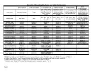
PRICING TABLE<br />
NAME START CONTINUE CREDITS/COIN COIN 1 COIN 2 COIN 3 COIN4 BILL<br />
USA1 2 2 1/25¢ .25¢ .25¢ $1.00<br />
USA2 2 1 1/25¢ .25¢ .25¢ $1.00<br />
USA3 1 1 1/25¢ .25¢ .25¢ $1.00<br />
USA4 1 1 1/50¢, 3/$1.00 .25¢ .25¢ $1.00<br />
USA5 2 1 1/50¢, 4/$1.00 .25¢ .25¢ $1.00<br />
USA6 1 1 1/50¢ .25¢ .25¢ $1.00<br />
USA7 1 1 1/50¢, 3/$1.00 .25¢ .25¢ $1.00<br />
USA8 2 2 1/50¢, 4/$1.00 .25¢ .25¢ $1.00<br />
USA9 3 2 1/25¢, 4/$1.00 .25¢ .25¢ $1.00<br />
USA10 3 3 1/25¢, 4/$1.00 .25¢ .25¢ $1.00<br />
USA 11 4 2 1/$1.00, 2/$1.50 .25¢ .25¢ $1.00<br />
USA 12 4 3 1/$1.00, 2/$1.75 .25¢ .25¢ $1.00<br />
USA 13 4 4 1/$1.00 .25¢ .25¢ $1.00<br />
USA ECA 3 3 1/25¢, 4/$1.00 $1.00 .25¢ .10¢ .05¢ $1.00<br />
GERMANY1 2 2 1/1DM, 6/5DM 1DM 5DM<br />
GERMANY2 2 1 1/1DM, 7/5DM 1DM 5DM<br />
GERMANY3 2 1 1/1DM, 8/5DM 1DM 5DM<br />
GERMANY4 2 1 1/1DM, 5/5DM 1DM 5DM<br />
GERMANY5 2 1 1/1DM, 6/5DM 1DM 5DM<br />
GERMANY ECA 2 2 1/1DM, 2/2DM, 6/5DM 5DM 2DM 1DM<br />
FRANCE1 2 2 2/5Fr, 5/10Fr 5Fr 10Fr<br />
FRANCE2 2 1 2/5Fr, 4/10Fr 5Fr 10Fr<br />
FRANCE3 2 1 1/5Fr, 3/10Fr 5Fr 10Fr<br />
FRANCE4 2 1 1/5Fr, 2/10Fr 5Fr 10Fr<br />
FRANCE5 2 1 2/5Fr, 5/10Fr, 11/2 X 10Fr 5Fr 10Fr<br />
FRANCE6 2 1 2/5Fr, 4/10Fr, 9/2 X 10Fr 5Fr 10Fr<br />
FRANCE7 2 1 1/5Fr, 3/10Fr, 7/2 X 10Fr 5Fr 10Fr<br />
FRANCE8 2 1 1/5Fr, 2/10Fr, 5/2 X 10Fr 5Fr 10Fr<br />
FRANCE9 2 1 1/3 X 1Fr, 2/5Fr 1Fr 5Fr<br />
FRANCE10 2 1 1/2 X 1Fr, 3/5Fr 1Fr 5Fr<br />
FRANCE11 2 1 1/3 X 1Fr, 2/5Fr, 5/2 X 5Fr 1Fr 5Fr<br />
FRANCE12 2 1 1/2 X 1Fr, 3/5Fr, 7/2 X 5Fr 1Fr 5Fr<br />
FRANCE ECA 1 1 1/10 Fr, 4/30 Fr 1Fr 5Fr<br />
FRANCE ECA 1 1 1 2/5Fr, 5/10Fr 1Fr 5Fr 10Fr 20Fr<br />
FRANCE ECA 2 1 1 2/5Fr, 4/10Fr 1Fr 5Fr 10Fr 20Fr<br />
FRANCE ECA 3 1 1 1/5Fr, 3/10Fr 1Fr 5Fr 10Fr 20Fr<br />
FRANCE ECA 4 1 1 1/5Fr, 2/10Fr 1Fr 5Fr 10Fr 20Fr<br />
FRANCE ECA 5 1 1 2/5Fr, 5/10Fr, 11/2 X 10Fr 1Fr 5Fr 10Fr 20Fr<br />
FRANCE ECA 6 1 1 2/5Fr, 4/10Fr, 9/2 X 10Fr 1Fr 5Fr 10Fr 20Fr<br />
FRANCE ECA 7 1 1 1/5Fr, 3/10Fr, 7/2 X 10Fr 1Fr 5Fr 10Fr 20Fr<br />
FRANCE ECA 8 1 1 1/5Fr, 2/10Fr, 5/2 X 10Fr 1Fr 5Fr 10Fr 20Fr<br />
FRANCE ECA 9 1 1 1/3 X 1Fr, 2/5Fr 1Fr 5Fr 10Fr 20Fr<br />
FRANCE ECA 10 1 1 1/2 X 1Fr, 3/5Fr 1Fr 5Fr 10Fr 20Fr<br />
FRANCE ECA 11 1 1 1/3 X 1Fr, 2/5Fr, 5/10Fr 1Fr 5Fr 10Fr 20Fr<br />
FRANCE ECA 12 1 1 1/2 X 1Fr, 3/5Fr, 7/10Fr 1Fr 5Fr 10Fr 20Fr<br />
FRANCE ECA 13 1 1 1/10Fr, 2/20Fr, 4/30Fr 1Fr 5Fr 10Fr 20Fr<br />
CANADA 2 2 1/$1.00, 2/$2.00 $1.00 $2.00 $1.00<br />
SWITZERLAND 1 2 2 1/1SFr, 6/5SFr 1SFr 5SFr<br />
SWITZERLAND 2 2 2 1/1SFr, 7/5SFr 1SFr 5SFr<br />
SWITZERLAND 3 2 2 1/1SFr, 8/5SFr 1SFr 5SFr<br />
ITALY 2 2 1/500Lit 500Lit 500Lit<br />
UK ECA1 1 1 1/50p, 3/£1.00 £1.00 50p 20p 10p<br />
UK ECA2 1 1 1/50p, 2/£1.00 £1.00 50p 20p 10p<br />
UK ECA3 1 1 1/30p, 2/50p, 5/£1.00 £1.00 50p 20p 10p<br />
UK4 1 1 1/50p, 3/£1.00 £1.00 50p<br />
UK5 1 1 1/50p, 2/£1.00 £1.00 50p 10p<br />
UK6 ECA 1 1 2/50p £1.00 50p 20p 10p<br />
UK7 ECA 1 1 3/£1.00 £1.00 50p 20p 10p<br />
SPAIN1 2 2 1/100Pta, 6/500Pta 100Pta 500Pta<br />
SPAIN2 2 2 1/100Pta, 5/500Pta 100Pta 500Pta<br />
AUSTRALIA1 2 2 1/3X20¢, 2/$1.00 .20¢ $1.00<br />
AUSTRALIA2 2 2 1/5X20¢, 1/$1.00 .20¢ $1.00<br />
JAPAN1 2 2 1/100Yen 100 Yen 100 Yen<br />
JAPAN2 2 2 2/100Yen 100 Yen 100 Yen<br />
AUSTRIA1 2 2 1/5Sch, 2/10Sch 5 Sch 10 Sch<br />
AUSTRIA2 2 2 1/2X5Sch, 3/2X10Sch 5 Sch 10 Sch<br />
BELGIUM1 2 2 1/20BF 20BF 20BF<br />
BELGIUM2 2 2 3/20BF 20BF 20BF<br />
BELGIUM3 2 2 2/20BF 20BF 20BF<br />
BELGIUM ECA 2 2 1/20BF 50BF 20BF 5BF<br />
SWEDEN 2 2 1/3X1SKr, 2/5SKr 1SKr 5SKr<br />
NEW ZEALAND1 1 1 1/3X20¢ 20¢ 20¢<br />
NEW ZEALAND2 1 1 1/2X20¢ 20¢ 20¢<br />
NETHERLANDS 2 2 1/1HFI, 3/2.5HFI 1HFI 2.5HFI<br />
FINLAND 2 2 1/1Fmk 1Fmk 1Fmk<br />
Operation 2-33
NAME START CONTINUE CREDITS/COIN COIN 1 COIN 2 COIN 3 COIN4 BILL<br />
NORWAY 2 2 1/2X1NKr, 3/5X1NKr 1NKr 1NKr<br />
DENMARK 2 2 1/2X1DKr, 3/5DKr, 7/2X5DKr 1DKr 5DKr<br />
ANTILLIES 2 2 1/25¢, 4/1G .25¢ 1G<br />
HUNGARY 2 2 1/2X10Ft, 3/2X20Ft 10Ft 20Ft<br />
Operation 2-34
HYDROTHUNDER <br />
C H A P T E R<br />
T H R E E<br />
SERVICE<br />
NOTICE: The term VGM refers to the video game machine.<br />
CAUTION: This VGM uses <strong>com</strong>plex electronic <strong>com</strong>ponents that are very sensitive to<br />
static electricity. Observe the following precautions before handling VGM electronics.<br />
Failure to do so may void your warranty and could damage electronic assemblies.<br />
• Before servicing electronics, turn off AC power to the VGM. Wait for capacitors to discharge.<br />
• Before touching or handling electronic assemblies, discharge static electricity on your body. To<br />
discharge this static, begin by touching the case of the Arcade Computer. Next, connect the line<br />
cord to a grounded outlet. Don’t turn on the VGM!<br />
• Store electronic assemblies in an anti-static area. Use anti-static bags to store or transport VGM<br />
circuit boards. Transport the hard drive in its shipping container.<br />
• Don’t remove or connect electronic assemblies when cabinet power is on. Otherwise, you’ll<br />
damage electronic assemblies and void the VGM warranty.<br />
• After you <strong>com</strong>plete maintenance or service, replace ground wires, shields, safety covers, etc. Install<br />
and tighten ground and mounting screws.<br />
Service 3-1
SERVICING<br />
Only qualified service personnel should repair VGM equipment. The following product guidelines apply to<br />
all video game operators and service personnel. Notes, cautions and warnings appear throughout this<br />
manual where they apply. Study the Safety pages before beginning service.<br />
• Battery<br />
CAUTION: If you install the battery incorrectly, it may explode! Avoid direct shorts<br />
across the terminals or from terminals to ground. These batteries are designed for<br />
very long life. Don’t attempt to recharge these batteries!<br />
CAUTION: Avoid an explosion! Replacement batteries must match the originals in<br />
size, voltage rating, and <strong>com</strong>position. Manufacturer re<strong>com</strong>mended equivalent types<br />
are acceptable. Store batteries in a safe place until you’ve <strong>com</strong>pleted repairs.<br />
Dispose of used batteries according to manufacturer instructions.<br />
A battery on the CPU Board retains data in memory during power disruptions. This battery is a 3-volt,<br />
lithium button cell of type CR 2032. Switch off power to the game. Unlock and remove the rear door.<br />
Remove the back of the Arcade Computer. The battery resides toward the edge of the motherboard,<br />
near the daughter board sockets. Carefully pry up the battery retaining lever. Then grasp the battery<br />
edges and remove the device. Set the battery aside.<br />
Note the “+” marking on one side of the replacement battery. When you install a battery, this “+”<br />
marking must face the battery retaining lever. After replacing the battery, set the system clock to the<br />
correct date and time. Also enter the Menu System and check or update system adjustments as<br />
necessary.<br />
• Coin Counter<br />
Switch off power to the VGM. Unlock the cash door and swing it open. Find the meter at the lower left<br />
corner of the vault opening. Record the meter count before testing or replacement.<br />
Locate the meter wires. Disconnect wiring at the connector. Remove two screws from the front<br />
bracket. The meter is a 5V D.C. meter. Assure that the replacement meter has a diode across the<br />
terminals to protect driver circuits.<br />
• Coin Mechanism<br />
Switch off power to the VGM. Unlock the coin door and swing it open. To clean or replace a coin<br />
mechanism, unlatch and remove it. After reinstallation, assure that the mechanism seats fully in its<br />
bracket. Close and lock the release latch. Then close the door. Enter the Menu System to change the<br />
coin mechanism setup. Test known good and bad coins to verify operation.<br />
• CPU Board<br />
NOTICE: Avoid damage to electronics! Turn off VGM power before servicing circuit<br />
boards or any electronic assembly. Never “hot plug” circuit boards.<br />
The CPU Board is part of the Arcade Computer. Switch off power to the VGM. Open and remove the<br />
rear door. The Arcade Computer is behind this door.<br />
To expose the CPU Board, loosen four metal thumbscrews. Don’t remove the screws. These screws<br />
reside at the top and bottom corners of the case. Slide off the back of the <strong>com</strong>puter. Disconnect the<br />
floppy disk power and data cables at the disk drive. Loosen the drive mounting screws. Lift the floppy<br />
drive out of the cabinet. Set it aside for reassembly. Remove the I/O Board brackets.<br />
Service 3-2
Remove the CPU Board power cables at the CPU Board. Remove the circuit board retention bars.<br />
Disconnect the Reset cable from the Filter Board and Motherboard, noting the orientation of the<br />
connectors. Remove the Filter Board Assembly, Video Card, and Network Card. Remove the floppy<br />
drive mounting bracket. Remove CPU Board mounting screws. Pinch the top of a CPU Board<br />
standoff and raise the board off the standoff. Repeat this procedure at the other standoffs. Lift the<br />
circuit board out of the cabinet and set it aside for reassembly. Use anti-static packaging from new<br />
parts to store boards that you won’t reinstall.<br />
• Dashboard and Steering Mechanism<br />
Switch off power to the VGM. Remove the control panel bolts on the right and left side of the cabinet.<br />
Open the coin door and release the latches on the left and right sides of the control panel. Support<br />
the steering wheel and lower the dash. Be sure that you don’t pinch cables in the hinge.<br />
Service 3-3
20-9275-2<br />
20-9347<br />
Dashboard Assembly<br />
Steering Wheel Assembly<br />
Inspect the motor, pulleys, and belt. If the belt is broken or shows signs of wear, replace it. Locate the<br />
two nuts on each side of the motor mounting bracket. Loosen all four bracket nuts. Rotate the tension<br />
adjustment bolt as necessary. Tighten this bolt until the belt is taut. Then restore correct tension by<br />
loosening the bolt one full turn. Tighten the motor bracket nuts.<br />
• Wheel Driver Board<br />
Switch off power to the VGM. Unlock and open the coin door and rear door. Note the orientation of<br />
the connector and other cables. Extract the harnesses from the board connectors. Remove mounting<br />
screws and washers from the Wheel Driver Board. Lift the board off its mounting posts. Handle the<br />
board by a heatsink. If you aren’t reinstalling the board, store it in an anti-static bag and protective<br />
container.<br />
Service 3-4
Dollar Bill Validator<br />
(Use MARS AE2451-U5 UL Recognized currency changer)<br />
Dollar bill validators or other currency acceptors may be installed in VGMs that were manufactured<br />
with the additional wiring connector. Switch off power to the VGM and unplug the AC line cord.<br />
Unlock the coin door and swing it open. Read the coin door label for additional information.<br />
Remove nuts, spacers, and cover plate from the door. Change switch settings or make adjustments<br />
before mounting the unit. If the manufacturer has supplied an adapter plate, place it over the door<br />
cutout. Install spacers on threaded studs. Align the validator mounting holes with the studs. Seat the<br />
unit in the door opening. Install and tighten the nuts. Attach the ground wire (green with yellow stripe)<br />
lug to the door ground stud. The stud is beside the hinge. Mate the wiring harnesses and press them<br />
together to fully seat connectors. Route wires away from door edges and hinge. Inspect the bill chute<br />
for proper alignment. Set the dollar bill validator to produce long output pulse widths, 1 pulse per<br />
dollar, and accept dollar bills only. To remove for service or replacement, reverse these steps.<br />
Plug in the line cord and turn on the VGM. From the Menu System, change the mechanism setup and<br />
pricing. Then test known good and bad bills to verify proper operation. Close and lock the coin door.<br />
• Fans<br />
Switch off power to the VGM. Remove the cabinet rear door. Remove the back of the Arcade<br />
Computer. To remove a fan, disconnect its power harness and remove the fan mounting screws.<br />
Note the fan orientation. Each fan has an arrow molded into its plastic case to indicate airflow<br />
direction. Be certain to reinstall the fans in the proper direction to assure airflow over circuitry.<br />
• Throttle Lever<br />
Switch off power to the VGM. Unlock and open the coin door. Unlatch and lower the dashboard.<br />
Remove three tamper-resistant bolts at the base of the lever. Lift off the throttle lever. Careful! Cable<br />
remains attached to the lever. To remove throttle assembly, unbolt the assembly cover. Support the<br />
assembly, then unbolt it from inside the control panel.<br />
• Hard Disk Drive<br />
Switch off power to the game. Unlock and remove the rear door. Remove the back of the Arcade<br />
Computer. Disconnect the DC power cable from the hard disk drive. Unplug the ribbon cable from the<br />
hard drive but leave it attached to the CPU board. Remove the drive mounting screws. Lift the drive<br />
out of the cabinet. Save the mounting screws for reuse in future hard drive installations. When<br />
returning a hard drive to your distributor, pack it in an anti-static bag. Box the drive in approved<br />
shipping container 08-8068.<br />
CAUTION: Hard disk drives are very fragile! Handle them with care. Keep disk drives<br />
away from magnets, heat and vibration. Don’t move a game with the power on.<br />
CAUTION: Don’t stack or drop hard disk drives. Use an anti-static bag and an<br />
approved shipping container to return the drive to your distributor.<br />
REINSTALLATION. Before mounting the hard drive in its bracket, install the drive mounting screws.<br />
To avoid damage during installation, mount the hard drive in the brackets before connecting cables.<br />
After a driver plays one game, the new drive copies data from other linked VGMs. Important! The<br />
data won’t copy if players are actively driving. Files transfer only when all VGMs return to Attract<br />
Mode.<br />
• Audio Amplifier Board<br />
Switch off power to the VGM. Unlock and open the rear door and the coin door. Note the orientation<br />
of the connector and other cables. Extract the harnesses from the board connectors. Remove<br />
mounting screws and washers from the Audio Board. Lift the board off its mounting posts. Handle the<br />
board by a heatsink. If you aren’t reinstalling the board, store it in an anti-static bag and protective<br />
container.<br />
Service 3-5
• Diego Interface Board<br />
Switch off power to the VGM. Unlock and open the rear door. Extract the harnesses from the board<br />
connectors. Remove mounting screws and washers from the Diego Board. Remove the Diego Board.<br />
Lift the board off its mounting posts. During reinstallation, tighten the screws: Start at the board’s<br />
center and work toward the outer edge. If you aren’t reinstalling the board, store it in an anti-static bag<br />
and protective container.<br />
• Speakers<br />
Switch off power to the VGM. Unbolt and remove the speaker grille from below the marquee. Note<br />
the orientation of speaker wires. Unbolt and remove the speakers. To remove subwoofer, unlock and<br />
open the rear door. Note the orientation of speaker wires. Unbolt and remove the speaker.<br />
• Marquee Light Box<br />
Switch off power to the VGM. Remove the speaker panel screws. Lift off the marquee glass and<br />
artwork to expose the interior of the light box.<br />
• Viewing Glass<br />
Switch off power to the game. Unlock and open the coin door. Unlatch and lower the dashboard.<br />
Remove the glass retaining bracket at the bottom center of the viewing glass. Carefully remove glass<br />
and set aside. Clean glass before reinstalling.<br />
• Monitor<br />
WARNING: The video monitor is very heavy, with most of the weight toward<br />
the front. Solidly support the monitor as you remove from it from the cabinet.<br />
WARNING: When operating the monitor outside the cabinet, use an isolation<br />
transformer. In normal operation, the monitor doesn’t require isolation from AC<br />
line voltage.<br />
Switch off power to the VGM. Unlock and open the coin door. Unlatch and lower the dashboard.<br />
Remove the viewing glass. Lift out the monitor bezel. Remove the flange nuts that secure the<br />
monitor's mounting brackets to its mounting panel. Carefully pull the monitor from the cabinet. Set the<br />
monitor in a safe place. Clean the face of the CRT and viewing glass before reinstalling the bezel and<br />
viewing glass.<br />
• Network Interface Board<br />
Switch off power to the VGM. Unlock and open the rear door. Remove the back of the Arcade<br />
Computer. Note the orientation of the cables. Loosen the header-mounting screw. Disconnect the<br />
network cables from the board header connectors. Remove the circuit board retention bars. Remove<br />
the board. If you aren’t reinstalling the board, store it in an anti-static bag and protective container.<br />
• Video Card<br />
Switch off power to the VGM. Unlock and open the rear door. Remove the back of the Arcade<br />
Computer. Loosen the header-mounting screw. Disconnect the video cable from the board header<br />
connector. Remove the circuit board retention bars. Remove the board. If you aren’t reinstalling the<br />
board, store it in an anti-static bag and protective container.<br />
• Filter Board<br />
Switch off power to the VGM. Unlock and open the rear door. Remove the back of the Arcade<br />
Computer. Note the orientation of the cables. Loosen the header-mounting screw. Disconnect the<br />
cables from the board header connectors. Remove the board. If you aren’t reinstalling the board,<br />
store it in an anti-static bag and protective container.<br />
Service 3-6
• DIMMs (Dual In-line Memory Modules)<br />
CAUTION: Static electricity builds up on your body. This static can damage or<br />
destroy sensitive circuits. Before touching or handling electronics, discharge static<br />
electricity by touching the power supply chassis.<br />
DIMM circuits contain the <strong>com</strong>puter read-write memory for this game. Switch off power to the game.<br />
Remove the cabinet rear door. Remove the back of the Arcade Computer. Unplug the ribbon cable<br />
from the floppy drive. Leave the other end of the cable attached to the CPU Board. Unscrew and<br />
remove the circuit board retention bars. Remove the floppy drive mounting bracket. Remove the<br />
floppy drive. Note DIMM positions. Press out on the locking retainer on each side of the DIMM. The<br />
DIMM should partially or <strong>com</strong>pletely pop out of its socket. Lift the DIMM from its socket. Handle the<br />
DIMM only by its edges.<br />
A<br />
B<br />
C<br />
DIMM Installation<br />
To reinstall memory circuits, hold the DIMM upright over its socket. Make sure the keying holes and<br />
notches are in their proper positions. Gently push the DIMM board into the socket, so that the board<br />
snaps into place under the locking retainer on each side of the socket. Be sure that the retainers mate<br />
tightly with DIMM board notches. Do not force a DIMM into its socket!<br />
Service 3-7
ARCADE COMPUTER MECHANICAL COMPONENTS<br />
Service 3-8
HYDROTHUNDER <br />
C H A P T E R<br />
F O U R<br />
PARTS<br />
WARNING: USE OF NON-MIDWAY PARTS OR CIRCUIT MODIFICATIONS MAY<br />
CAUSE SERIOUS INJURY OR EQUIPMENT DAMAGE! USE ONLY MIDWAY<br />
AUTHORIZED PARTS.<br />
For safety and reliability, substitute parts and modifications are not re<strong>com</strong>mended.<br />
Substitute parts or modifications may void EMC directives or FCC type acceptance.<br />
Parts 4-1
CABINET FRONT VIEW<br />
03-9306<br />
08-7456-16<br />
4420-01141-00<br />
A-22506<br />
24-8809<br />
4408-01128-00<br />
5555-15098-00<br />
5675-15639-00<br />
01-10819<br />
4420-01141-00<br />
4008-01113-06<br />
Parts 4-2
MARQUEE ASSEMBLY<br />
4108-01219-11<br />
03-8252-2<br />
31-3440<br />
08-7456-17<br />
03-9373-1<br />
4108-01193-10B<br />
01-13562.1<br />
Parts 4-3
CABINET REAR VIEW<br />
Parts 4-4
REAR DOOR ASSEMBLY<br />
A-20281<br />
4420-01141-00<br />
01-11285<br />
20-10350<br />
4320-01123-20B<br />
04-10149.1<br />
4320-01123-20B<br />
01-8989<br />
01-7264<br />
4108-01219-11<br />
03-7602<br />
4420-01141-00<br />
01-11291<br />
Parts 4-5
COIN DOOR ASSEMBLY<br />
(See coin door application chart for assembly and part numbers)<br />
24-8768<br />
#259 OR #555<br />
Parts 4-6
COIN DOOR ASSEMBLY cont’d<br />
(See coin door application chart for assembly and part numbers)<br />
A-21069<br />
Parts 4-7
DASH ASSEMBLY<br />
A-23303<br />
20-10209-2<br />
20-10209-1<br />
4020-01178-08<br />
4420-01141-00<br />
04-12773<br />
A-23100<br />
03-9945<br />
4006-01005-10<br />
A-23327<br />
4010-01148-12<br />
20-10209-3<br />
4008-01229-32B<br />
01-15053<br />
04-12646<br />
20-10157<br />
07-6704-06<br />
4320-01123-10B<br />
03-9949<br />
01-15102<br />
31-3442<br />
31-3441<br />
03-9312<br />
02-5351.1<br />
20-10189<br />
02-5164<br />
4008-01093-10B<br />
4427-01183-00<br />
20-10503.1<br />
4701-00005-00B<br />
4020-0110024<br />
STEERING MECHANISM<br />
20-10134<br />
Parts 4-8
THROTTLE ASSEMBLY<br />
A-23327<br />
04-12643.1<br />
20-10517<br />
20-8712-50<br />
01-14947<br />
20-8712-18<br />
04-11295<br />
4410-01129-00<br />
02-5352<br />
03-9778<br />
01-14896<br />
03-9920<br />
10-532<br />
4410-01129-00<br />
4700-00021-00<br />
4010-01070-08<br />
01-14897<br />
10-531<br />
02-5337<br />
4020-01178-10<br />
A-23220<br />
4006-01076-04<br />
17-1131<br />
02-5340<br />
02-5338<br />
02-5339<br />
03-9774<br />
4700-00021-00<br />
4010-01070-10<br />
04-11297<br />
4010-01070-08<br />
Parts 4-9
THROTTLE LEVER ASSEMBLY<br />
A-23100<br />
03-9890.1<br />
20-10541<br />
4006-01005-10<br />
04-12646<br />
24-8880<br />
20-10421<br />
02-5341<br />
03-9889<br />
4010-01148-12<br />
20-10494<br />
Parts 4-10
ARCADE COMPUTER ASSEMBLY<br />
04.12574.2<br />
Parts 4-11
ARCADE COMPUTER MOTHERBOARD AND PERIPHERAL CARDS<br />
Parts 4-12
ARCADE COMPUTER MECHANICAL COMPONENTS<br />
Parts 4-13
ARCADE COMPUTER MOTHERBOARD AND CPU<br />
NOTE 1: Although This Motherboard Is A Stock Item Used On Many Personal Computers, It Requires A<br />
Custom Operating System To Function In This Game.<br />
NOTE 2: DIMM and CPU modules from other manufacturers may be electrically equivalent or better than<br />
those illustrated here, but performance has not been verified with alternate <strong>com</strong>ponents. Check<br />
with your distributor for information before attempting to use other than factory authorized parts.<br />
NOTE 3: Celeron and Slot 1 are registered trademarks of Intel.<br />
Parts 4-14
COMPUTER MOTHERBOARD ASSEMBLY<br />
20-10554<br />
Field Replaceable Parts<br />
DESIGNATION PART NUMBER FUNCTION DESCRIPTION<br />
B 5882-16135-00 Memory Backup 3Volt Lithium Battery<br />
FAN 20-10549 Processor Cooling Fan with Bracket<br />
J8A1 5882-13046-00 Shunt Jumper Startup Configuration<br />
-- 20-10553 Processor Assembly Celeron 333 Processor<br />
-- 20-10557 Dual Inline Memory Module 64MB SDRAM DIMM<br />
Parts 4-15
NETWORK INTERFACE CARD ASSEMBLY<br />
20-10550<br />
Field Replaceable Parts<br />
DESIGNATION PART NUMBER FUNCTION DESCRIPTION<br />
U2 -- Instruction ROM Not required in this game<br />
Parts 4-16
VIDEO GRAPHICS CARD ASSEMBLY<br />
20-10551<br />
Field Replaceable Parts<br />
DESIGNATION PART NUMBER FUNCTION DESCRIPTION<br />
J6 -- Graphics Mode Select Not required in this game<br />
FILTER CARD ASSEMBLY<br />
04-12651<br />
Field Replaceable Parts<br />
DESIGNATION PART NUMBER FUNCTION DESCRIPTION<br />
F1-F5 5060-15633-00 EMI Filter 2200 pF Dual Capacitor<br />
L1-L5 5556-14181-00 EMI Filter Ferrite Bead Inductor<br />
Parts 4-17
AUDIO AMPLIFIER BOARD ASSEMBLY<br />
04-12529.1<br />
Field Replaceable Parts<br />
DESIGNATION PART NUMBER FUNCTION DESCRIPTION<br />
U1-U2 5370-15163-00 Audio Amplifier LM3403 Quad Amplifier<br />
U3 5370-15984-00 Audio Output TDA1560Q Power Amplifier<br />
U4 5370-15833-00 Audio Output TDA7375 Power Amplifier<br />
U5 5250-13302-00 Voltage Regulator +5VDC 5% Fixed Regulator<br />
U6 -- None Not required in this game<br />
Parts 4-18
DIEGO INTERFACE BOARD ASSEMBLY<br />
04-12522.4<br />
Field Replaceable Parts<br />
DESIGNATION PART NUMBER FUNCTION DESCRIPTION<br />
L37 5551-16093-00 EMI Filter 47uH Inductor<br />
Q1 5190-15997-00 Transistor 2N2369 NPN<br />
Q2 5370-12602-00 Driver Circuit ULN2064B IC<br />
Q3-Q4 5160-14035-00 Transistor 2N3904 NPN<br />
U11 5370-16103-00 Voltage Regulator LM34801-3.3<br />
Parts 4-19
WHEEL DRIVER BOARD ASSEMBLY<br />
04-11127<br />
Field Replaceable Parts<br />
DESIGNATION PART NUMBER FUNCTION DESCRIPTION<br />
BR1 5100-13945-00 Bridge Rectifier 100V 6A SIP<br />
D2-D3 5070-14526-00 Diode Rectifier MR751 100V 6A<br />
D7 5070-15115-00 Dual Rectifier MUR1605 50V 8A SIP<br />
F1-F2 5731-14094-00 Circuit Protection 4A 125V 5x20mm SB Fuse<br />
Q1 5162-08976-00 Transistor 2N6427 NPN<br />
Q2 5160-14035-00 Transistor 2N3904 NPN<br />
U1-U2 5370-12602-00 Driver Circuit ULN2064B IC<br />
U4 5370-14069-00 Power Driver LM12 Op Amplifier<br />
Parts 4-20
ELECTRONIC CABLE ASSEMBLIES<br />
SERIAL COMMUNICATIONS CABLE (NULL MODEM DB-9F TO DB-9F)<br />
20-10532<br />
VIDEO COMMUNICATIONS CABLE (SHIELDED DB-15 TO DB-15)<br />
5797-13171-00<br />
Parts 4-21
ELECTRONIC CABLE ASSEMBLIES<br />
AUDIO AMPLIFIER CABLE (MINIATURE STEREO PHONE PLUG TO PHONO PLUGS)<br />
04-12578-2<br />
COMPUTER RESET CABLE (2-PIN PLUG TO LOCKING 2-PIN PLUG)<br />
04-12657<br />
Parts 4-22
LINE CORD APPLICATION CHART<br />
Part Number<br />
5850-<br />
13271-<br />
00<br />
5850-<br />
13272-<br />
00<br />
5850-<br />
13273-<br />
00<br />
5850-<br />
13275-<br />
00<br />
5850-<br />
13276-<br />
00<br />
5850-<br />
13277-<br />
00<br />
5850-<br />
13278-<br />
00<br />
Country<br />
USA „<br />
UK „<br />
Italy „<br />
Japan „<br />
New Zealand „<br />
Germany „<br />
Spain „<br />
Denmark „<br />
Finland „<br />
Holland „<br />
Norway „<br />
Switzerland „<br />
Hungary „<br />
Canada „<br />
Austria „<br />
France „<br />
Australia „<br />
Belgium „<br />
Saudi Arabia „<br />
India „<br />
Indonesia „<br />
TYPICAL LINE CORD<br />
Parts 4-23
COIN DOOR APPLICATION CHART<br />
ELECTRO-MECHANICAL COIN DOOR ASSEMBLIES<br />
Part<br />
Number<br />
09-50000-<br />
Country<br />
02 03 06 07 09 11 13 14 15 17 18 20 22 23 24 33 38 86 87<br />
USA „<br />
UK „<br />
France „<br />
Italy „<br />
Japan „<br />
New Zealand „<br />
Germany „<br />
Spain „<br />
Denmark „<br />
Finland „<br />
Holland „<br />
Norway „<br />
Switzerland „<br />
Hungary „<br />
Austria „<br />
Australia „<br />
Belgium „<br />
Saudi Arabia „<br />
POWER TRANSFORMER ASSEMBLIES<br />
Part Number<br />
Line Power<br />
TRANSFORMER APPLICATION CHART<br />
5610-14927-00 5610-14926-01 5610-15275-00<br />
120 VAC 60 HZ „<br />
230 VAC 50HZ „<br />
100 VAC 50HZ „<br />
TYPICAL POWER TRANSFORMER ASSEMBLY<br />
Parts 4-24
HYDROTHUNDER <br />
C H A P T E R<br />
F I V E<br />
WIRING & CIRCUIT<br />
INFORMATION<br />
WARNING: Failure to reconnect all ground wires or to replace metal shields and covers<br />
with each mounting screw installed and securely tightened may result in radio<br />
frequency interference.<br />
Do not disconnect or connect cables, wiring harness, circuit boards, <strong>com</strong>puter circuit<br />
cards, jumpers, etc., with the power ON. Doing so can damage game electronic<br />
<strong>com</strong>ponents and void your warranty.<br />
Wiring 5-1
CABINET WIRING DIAGRAM<br />
Wiring 5-2
POWER WIRING DIAGRAM<br />
Wiring 5-3
COMPUTER MOTHERBOARD ASSEMBLY<br />
20-10554<br />
MOTHERBOARD CONNECTOR AND JUMPER STATUS<br />
(NOTES FOR CHART ON FOLLOWING PAGE)<br />
NOTES:<br />
1. Jumper is not required for this game. No telephone connection necessary for operation.<br />
2. Jumper is not required for this game. A proprietary network is used for game linking.<br />
3. Connections not required for this game. No ATAPI devices (CD ROM) are used in this game.<br />
4. Jumper is not required for this game. The tamper detection security feature is not installed.<br />
5. Connect processor module fan to this jack. Computer may be<strong>com</strong>e unreliable if processor overheats.<br />
6. Connect processor module to this jack. The 242-pin socket accepts single microprocessor modules.<br />
7. Connections not required for this game. The case cooling fans connect directly to the power supply.<br />
8. Connections not required for this game. No SCSI device (Hard Disk Drive) are used in this game.<br />
9. Connect the reset cable from the Filter Card Assembly to this jack. No front panel devices are used.<br />
10. Jumper must be set over pins 1 & 2 for this game. Game will not run if jumper is incorrect or missing.<br />
* Replacement Motherboards may not include this jumper. Refer to Parts to order extra shunt jumpers.<br />
Wiring 5-4
MOTHERBOARD CONNECTOR AND JUMPER STATUS CHART<br />
DESIGNATION LOCATION FUNCTION MEANING SETTING DEFAULT<br />
J1A1 LOWER RIGHT WAKE NOT USED IN THIS OPEN „<br />
NEAR BOARD ON GAME (NO 1 & 2<br />
(NOTE 1) EXPANSION SLOT RING TELEPHONE)<br />
J1E1 LOWER CENTER WAKE NOT USED IN THIS OPEN „<br />
NEAR BOARD ON GAME (NO<br />
(NOTE 2) EXPANSION SLOT LAN PC LAN)<br />
J1F2 LOWER CENTER CD AUDIO NOT USED IN THIS OPEN „<br />
NEAR BOARD INPUT GAME (NO<br />
(NOTE 3) EXPANSION SLOT CIRCUIT CD PLAYER)<br />
J2F1 LOWER CENTER CD DATA NOT USED IN THIS OPEN „<br />
NEAR BOARD INPUT GAME (NO<br />
(NOTE 3) EXPANSION SLOT CIRCUIT CD PLAYER)<br />
J2F2 LOWER CENTER TELEPHONY NOT USED IN THIS OPEN „<br />
NEAR BOARD INPUT GAME (NO<br />
(NOTE 1) EXPANSION SLOT CIRCUIT TELEPHONE)<br />
J2F3 LOWER CENTER AUXILLIARY NOT USED IN THIS OPEN „<br />
NEAR BOARD INPUT GAME (NO<br />
(NOTE 3) EXPANSION SLOT CIRCUIT AUX DEVICES)<br />
J3F1 MIDDLE CENTER CHASSIS NOT USED IN THIS OPEN „<br />
NEAR CPU INTRUSION GAME (NO 1 & 2<br />
(NOTE 4) AND FAN CIRCUIT INTRUSION)<br />
J3F2 MIDDLE CENTER PROCESSOR TWO SPEED FAN OPEN<br />
NEAR CPU FAN FOR PROCESSOR 1, 2, & 3 „<br />
(NOTE 5) AND FAN CIRCUIT COOLING<br />
J4J1 CENTER LEFT SYSTEM SYSTEM OPEN<br />
MODULE WITH MICRO- MICRO- FILLED „<br />
(NOTE 6) FAN ASSEMBLY PROCESSOR PROCESSOR<br />
J4M1 CENTER LEFT PROCESSOR CONTROLLED FAN OPEN „<br />
NEAR CPU FAN FOR PROCESSOR 1, 2, & 3<br />
(NOTE 7) MODULE CIRCUIT COOLING<br />
J7M1 UPPER LEFT CASE CONTROLLED FAN OPEN „<br />
NEAR POWER & FAN FOR HARD DISK 1, 2, & 3<br />
(NOTE 7) FLOPPY JACKS CIRCUIT DRIVE COOLING<br />
J8J1 UPPER LEFT SCSI NOT USED IN THIS OPEN „<br />
BETWEEN HARD DRIVE GAME (NO 1 & 2<br />
(NOTE 8) & FLOPPY JACKS INDICATOR SCSI DRIVES)<br />
J8FR UPPER CENTER FRONT ONLY RESET OPEN<br />
NEAR HARD DISK PANEL PINS ARE USED 1 & 2 „<br />
(NOTE 9) DRIVE JACKS DEVICES IN THIS GAME<br />
J8A1 UPPER RIGHT CONFIGU- STARTS SYSTEM OPEN<br />
NEAR BATTERY RATION SETUP ROUTINE 1 & 2 „<br />
(NOTE 10) AND SPEAKER SELECT OR OPERATION 2 & 3<br />
Wiring 5-5
NETWORK INTERFACE CARD ASSEMBLY<br />
20-10550<br />
NETWORK INTERFACE LED INDICATOR STATUS CHART<br />
DESIGNATION LOCATION FUNCTION COLOR STATE MEANING<br />
LED 1<br />
(LNK)<br />
LEFT CENTER<br />
UNDER JACK<br />
LINK VERIFY<br />
INDICATOR<br />
GREEN OFF NOT IN USE<br />
(NO GAME LINK)<br />
ON<br />
NORMAL<br />
OPERATION<br />
BLINKING LINK FAULT<br />
(NOTE 1)<br />
LED 2<br />
(ACT)<br />
RIGHT CENTER<br />
UNDER JACK<br />
ACTIVITY<br />
INDICATOR<br />
GREEN OFF NOT IN USE<br />
(NO DATA)<br />
ON RECEIVING DATA<br />
(NOTE 2)<br />
BLINKING NORMAL<br />
OPERATION<br />
NOTES:<br />
1. Intermittent cable or hub problems may cause blinking. Must be continuous at all times when linked.<br />
2. Blinks as data packets are exchanged. May appear almost continuous during heavy network activity.<br />
Wiring 5-6
VIDEO GRAPHICS CARD ASSEMBLY<br />
20-10551<br />
VIDEO GRAPHICS CONNECTOR AND JUMPER STATUS CHART<br />
DESIGNATION LOCATION FUNCTION MEANING SETTING DEFAULT<br />
J1 LEFT CENTER VIDEO GRAPHIC OPEN<br />
(DB-15 ON SIGNAL INFORMATION 1-15 „<br />
(NOTE 1) BRACKET) OUTPUT TO INTERFACE<br />
J2-J7 NONE --- NOT USED OPEN „<br />
(NOTE 2)<br />
JP2 NONE --- NOT USED OPEN „<br />
(NOTE 2)<br />
NOTES:<br />
1. Connects to Interface Board Assembly through shielded cable. Does not connect directly to monitor.<br />
2. Manufacturer option connectors and jumpers. Not required for this game.<br />
Wiring 5-7
AUDIO AMPLIFIER BOARD ASSEMBLY<br />
04-12529.1<br />
AUDIO AMPLIFIER LED INDICATOR STATUS CHART<br />
DESIGNATION LOCATION FUNCTION COLOR STATE MEANING<br />
LED 1<br />
(CR1)<br />
UPPER CENTER<br />
NEAR C3<br />
FAULT<br />
INDICATOR<br />
RED OFF NORMAL<br />
OPERATION<br />
ON LOCKED UP<br />
(NOTE 1)<br />
BLINKING OVERLOAD<br />
(NOTE 2)<br />
LED 2<br />
(CR2)<br />
LOWER CENTER<br />
NEAR U2 & U6<br />
FAULT<br />
INDICATOR<br />
RED OFF NORMAL<br />
OPERATION<br />
ON LOCKED UP<br />
(NOTE 1)<br />
BLINKING OVERLOAD<br />
(NOTE 2)<br />
NOTES:<br />
1. Output protection circuit has been activated. Clear fault and remove power to attempt a circuit reset.<br />
2. Intermittent audio overload or overheating may cause blinking. LED should flash only during start up.<br />
Wiring 5-8
DIEGO INTERFACE BOARD ASSEMBLY<br />
04-12522.4<br />
DIEGO INTERFACE BOARD SWITCHES<br />
DESIGNATION LOCATION FUNCTION POSITIONS STATE MEANING<br />
S1-3 RIGHT CENTER<br />
NEAR JP7 & JP8<br />
GAME<br />
MODES<br />
2 OFF* NORMAL<br />
OPERATION<br />
ON FIXED IN<br />
TEST MODE<br />
S1-4 RIGHT CENTER<br />
NEAR JP7 & JP8<br />
CABINET<br />
SIZE<br />
2 OFF STANDARD<br />
25” CABINET<br />
ON* 39” CABINET<br />
S1-8 RIGHT CENTER<br />
NEAR JP7 & JP8<br />
RESET<br />
MODES<br />
2 OFF WATCHDOG<br />
DISABLED<br />
ON* WATCHDOG<br />
ENABLED<br />
NOTES:<br />
1. Use S1-3 only during testing or troubleshooting. The game will not start if this switch is left ON.<br />
2. Use S1-4 to set game type. The speakers and leader lights will not work properly if set incorrectly.<br />
3. Use S1-8 only during testing or troubleshooting. The game may lock up or freeze if this is disabled.<br />
4. S1-1, -2, -5, -6, and -7 have no assigned function. Leave these switches in their OFF positions.<br />
Wiring 5-9
DIEGO INTERFACE BOARD LED INDICATOR STATUS CHART<br />
DESIGNATION LOCATION FUNCTION COLOR STATE MEANING<br />
LED 1 MIDDLE CENTER INDICATOR GREEN OFF NOT IN USE<br />
(D1) NEAR JP12 & U10<br />
ON LOCKED UP<br />
(NOTE 1)<br />
BLINKING NORMAL<br />
LED 2<br />
(D2)<br />
LED 3<br />
(D3)<br />
LED 4<br />
(D4)<br />
LED 5<br />
(D5)<br />
MIDDLE CENTER<br />
NEAR JP12 & U10<br />
MIDDLE CENTER<br />
NEAR JP12 & U10<br />
MIDDLE CENTER<br />
NEAR JP12 & U10<br />
UPPER LEFT<br />
NEAR JP13 & L37<br />
OPERATION<br />
INDICATOR RED OFF NOT IN USE<br />
ON LOCKED UP<br />
(NOTE 1)<br />
BLINKING NORMAL<br />
OPERATION<br />
INDICATOR GREEN OFF NOT IN USE<br />
ON LOCKED UP<br />
(NOTE 2)<br />
BLINKING NORMAL<br />
OPERATION<br />
INDICATOR RED OFF NOT IN USE<br />
POWER<br />
INDICATOR<br />
ON LOCKED UP<br />
(NOTE 2)<br />
BLINKING NORMAL<br />
OPERATION<br />
RED OFF NO<br />
POWER<br />
ON<br />
NORMAL<br />
OPERATION<br />
BLINKING POWER FAULT<br />
(NOTE 3)<br />
NOTES:<br />
1. LED 1 and LED 2 are active on all versions of this board. LEDs may flash together during game start<br />
up. If these LEDs are always ON, there may be a fault that has caused the game freeze or lock up.<br />
2. LED 3 and LED 4 are active on some versions of this board. May flash together during game start up.<br />
If these LEDs are always ON, there may be a fault that has caused the game to freeze or lock up.<br />
3. LED 5 monitors a regulated power supply voltage source. Must be on continuously at all times. Flash<br />
or blinking indicates an intermittent connection, a power problem, a circuit fault, etc.<br />
Wiring 5-10
DIEGO INTERFACE CONNECTOR AND JUMPER STATUS CHART<br />
DESIGNATION LOCATION FUNCTION MEANING SETTING DEFAULT<br />
J1 & JP1 UPPER RIGHT VIDEO SIGNALS FROM OPEN<br />
BETWEEN INPUT COMPUTER VIDEO J1 ALL „<br />
(NOTE 1) JP2 AND JP16 SIGNALS GRAPHICS CARD JP1 ALL<br />
J2 & J3 LOWER CENTER SERIAL NOT USED IN THIS OPEN „<br />
BETWEEN COMM GAME (NO<br />
(NOTE 2) JP7 & JP10 SIGNALS USB COMM)<br />
JP2 UPPER RIGHT VIDEO SIGNALS TO OPEN<br />
BETWEEN OUTPUT GAME VIDEO JP2 ALL „<br />
J1 & JP6 SIGNALS MONITOR<br />
JP3 UPPER RIGHT BLUE MATCHES OPEN „<br />
BETWEEN VIDEO DRIVE LEVEL 1 & 2<br />
(NOTE 3) JP1 & JP6 LEVEL TO MONITOR 2 & 3<br />
JP4 UPPER RIGHT GREEN MATCHES OPEN „<br />
BETWEEN VIDEO DRIVE LEVEL 1 & 2<br />
(NOTE 3) JP1 & JP6 LEVEL TO MONITOR 2 & 3<br />
JP5 UPPER RIGHT RED MATCHES OPEN „<br />
BETWEEN VIDEO DRIVE LEVEL 1 & 2<br />
(NOTE 3) JP1 & JP6 LEVEL TO MONITOR 2 & 3<br />
JP6 UPPER RIGHT VIDEO LOCKS VIDEO OPEN „<br />
BETWEEN SYNC MONITOR TO 1 & 2<br />
(NOTE 4) L7 & U1 POLARITY SYNC SIGNAL 2 & 3<br />
JP7 LOWER RIGHT PLAYER SIGNALS FROM OPEN<br />
NEAR INPUT SWITCHES AND JP7 ALL „<br />
J3 & JP8 SIGNALS STEERING WHEEL<br />
JP8 LOWER RIGHT OPERATOR SIGNALS FROM OPEN<br />
NEAR INPUT CURRENCY AND JP8 ALL „<br />
JP7 & S1 SIGNALS TEST SWITCHES<br />
JP9 CENTER LEFT WHEEL STEERING MOTOR OPEN<br />
NEAR DRIVER FEEDBACK AND JP9 ALL „<br />
JP11 & U5 SIGNALS LEADER LIGHTS<br />
JP10 LOWER LEFT COIN INDIVIDUAL OPEN<br />
BETWEEN OUTPUT COIN METER JP10 ALL „<br />
J2 & P1 SIGNALS DRIVE CIRCUITS<br />
JP11 CENTER LEFT GAME WATCHDOG OPEN<br />
BETWEEN RESET TIMER JP11 ALL „<br />
C134 & JP9 SIGNAL CIRCUIT<br />
JP12 CENTER RIGHT BOARD CONNECTOR USED OPEN „<br />
NEAR TEST FOR CIRCUIT JP12 ALL<br />
S1 & U8 SIGNALS DEVELOPMENT<br />
JP15 & P1 LOWER RIGHT SERIAL DATA EXCHANGE OPEN<br />
NEAR COMM TO COMPUTER JP15<br />
(NOTE 1) JP10 & U7 SIGNALS CIRCUITS P1 „<br />
NOTES:<br />
1. Connectors wired in parallel. Use based on type of interconnect cable connector.<br />
2. Alternate forms of <strong>com</strong>munications. Not required for this game.<br />
3. Jumper not required for production video monitors. Install for early production Neotec or other units.<br />
4. Jumper factory set for production video monitors. Change for older positive sync video monitors.<br />
Wiring 5-11
WHEEL DRIVER BOARD ASSEMBLY<br />
04-11127<br />
WHEEL DRIVER BOARD LED INDICATOR STATUS CHART<br />
DESIGNATION LOCATION FUNCTION COLOR STATE MEANING<br />
LED 1 RIGHT CENTER INDICATOR RED OFF NOT IN USE<br />
NEAR C5 & P2<br />
ON<br />
NORMAL<br />
OPERATION<br />
BLINKING POWER FAULT<br />
(NOTE 1)<br />
NOTES:<br />
1. LED 1 monitors a regulated power supply voltage source. Must be on continuously at all times. Flash<br />
or blinking indicates an intermittent connection, a power problem, a circuit fault, etc.<br />
Wiring 5-12
HYDROTHUNDER <br />
C H A P T E R<br />
S I X<br />
TROUBLESHOOTING<br />
NOTICE: The term VGM refers to the video game machine.<br />
CAUTION: This VGM uses <strong>com</strong>plex electronic <strong>com</strong>ponents that are very sensitive to<br />
static electricity. Observe the following precautions before handling VGM electronics.<br />
Failure to do so may void your warranty and could damage electronic assemblies.<br />
• Before servicing electronics, turn off AC power to the VGM. Wait for capacitors to discharge.<br />
• Before touching or handling electronic assemblies, discharge static electricity on your body. To<br />
discharge this static, begin by connecting the line cord to a grounded outlet. Don’t turn on the<br />
VGM! Next, touch the safety ground stud of the power supply chassis.<br />
• Store electronic assemblies in an anti-static area. Use anti-static bags to store or transport VGM<br />
circuit boards. Transport the hard drive in its shipping container.<br />
• Don’t remove or connect electronic assemblies when cabinet power is on. Otherwise, you’ll<br />
damage electronic assemblies and void the VGM warranty.<br />
• After you <strong>com</strong>plete maintenance or service, replace ground wires, shields, safety covers, etc.<br />
Install and tighten ground and mounting screws.<br />
Troubleshooting 6-1
Coin Mechanism and Pricing Troubleshooting Table<br />
SYMPTOM CAUSE REQUIRED ACTION<br />
• VGM (video game machine)<br />
accepts currency or tokens,<br />
but number of credits per<br />
coin or bill is incorrect.<br />
• VGM won’t accept currency<br />
or tokens.<br />
• VGM won’t start.<br />
• Audio and video are present.<br />
• Coin indicators don’t light<br />
Improper settings at<br />
Pricing Menu<br />
Faulty wiring<br />
Improper currency<br />
Faulty coin<br />
mechanism<br />
Tilted coin<br />
mechanism or VGM<br />
1. Enter Menu System by pressing and holding<br />
TEST MODE switch inside coin door. From<br />
Diagnostics Menu, choose SWITCH TEST. Use<br />
tests to confirm operation of switches.<br />
2. From Adjustments Menu, choose PRICING<br />
MENU. Verify that units and credits are set<br />
correctly.<br />
1. Check that cabinet wiring is correct for this VGM.<br />
2. Assure that coin meter and coin switches<br />
connect properly to control input wires.<br />
1. Unlock and open cash door. Empty cash box.<br />
Inspect revenue for counterfeit currency.<br />
2. Check vault. Remove any items that block path<br />
from mechanism.<br />
1. Unlock and open coin door. Check each<br />
mechanism for proper mounting.<br />
2. Remove mechanism.<br />
3. Clear currency path.<br />
4. Reinstall mechanism and latch it.<br />
1. Verify that mechanism is level after doors close.<br />
2. Repair or replace coin door if it is bent or<br />
damaged.<br />
3. If necessary, adjust cabinet leg levelers to keep<br />
mechanisms vertical.<br />
Burned-out bulb 1. Burned-out bulbs may appear white or darkened.<br />
Check continuity with DVM.<br />
2. Replace burned-out bulb with same type.<br />
Open fuse circuit 1. Check fuse continuity with DVM.<br />
2. If fuse is blown, replace fuse with same type.<br />
3. If fuse isn’t blown, check wiring.<br />
CAUTION: Don’t remove or install any connector when power is turned on. Installation<br />
under power will damage the circuit boards or hard disk drive and void the warranty.<br />
Troubleshooting 6-2
VGM Startup Troubleshooting Table<br />
SYMPTOM CAUSE REQUIRED ACTION<br />
• VGM (video game machine)<br />
doesn’t start.<br />
• VGM appears <strong>com</strong>pletely<br />
non-functional.<br />
• No audio<br />
• No illumination<br />
• No video display<br />
Power problem<br />
Improper line voltage<br />
switch setting<br />
Open fuse<br />
Faulty wiring<br />
Arcade <strong>com</strong>puter<br />
problem<br />
1. Check that VGM power switch is on.<br />
2. Inspect <strong>com</strong>puter to see if fans are turning. If<br />
not: Is <strong>com</strong>puter power supply connected to its<br />
power cable? Is <strong>com</strong>puter power supply turned<br />
on?<br />
3. Plug VGM into AC power outlet. Verify presence<br />
of AC line voltage.<br />
Turn off VGM power. Unplug AC line cord. Check<br />
line voltage switch. If necessary, set it to agree<br />
with local AC line voltage. Retest VGM.<br />
1. Turn off VGM power. Examine AC fuse on power<br />
chassis, under <strong>com</strong>puter.<br />
2. Examine DC fuses on cabinet wall or electronic<br />
equipment shelf.<br />
3. Replace faulty fuses with identically rated parts.<br />
4. Turn on VGM power. If fuse opens again, check<br />
DC wiring harness and connectors.<br />
1. Remove line cord. Test line cord, power plug,<br />
and IEC connector for breaks or damage. Verify<br />
continuity of each wire in cord. Install cord at<br />
power chassis. Press connector firmly to seat it.<br />
2. Check <strong>com</strong>puter cord in same manner.<br />
3. Assure that cabinet wiring harness connectors<br />
fully seat in corresponding power supply and<br />
board connectors.<br />
4. Inspect wiring for breaks or damage.<br />
Turn off power for one minute and turn VGM on<br />
again. Power On Self-Test checks electronics.<br />
Screen may report errors. If video circuits don’t<br />
operate properly, <strong>com</strong>puter produces series of<br />
beeps. (See Error Message Troubleshooting<br />
Table.)<br />
Location of Power Supply<br />
Troubleshooting 6-3
VGM Startup Troubleshooting Table, continued<br />
SYMPTOM CAUSE REQUIRED ACTION<br />
• VGM (video game machine)<br />
appears non-functional.<br />
• Currency acceptor price<br />
indicator is illuminated.<br />
Power problem<br />
Faulty wiring<br />
Improper jumper or<br />
DIP switch settings<br />
Faulty circuit boards<br />
or arcade <strong>com</strong>puter<br />
1. Inspect circuit boards under low-light conditions.<br />
LEDs glow if processor circuits receive voltage.<br />
Fan should be turning. These indications prove<br />
presence of DC from power supply. Still,<br />
voltages or signals may not be normal.<br />
Computer has no internal LEDs.<br />
2. Turn on VGM power. Using 20-volt DC setting on<br />
digital voltmeter, measure DC voltages at power<br />
connector pins. (Power supply voltage isn’t<br />
adjustable.)<br />
3. Using 2-volt AC setting on digital voltmeter,<br />
measure same DC voltages as above. Any<br />
reading here indicates that supply voltages are<br />
unstable and may contain ripple or noise.<br />
Turn off VGM power. Assure that wiring harness<br />
connectors fully seat onto mating board<br />
connectors. Verify that harness connects to<br />
<strong>com</strong>puter. Check other connectors in same way.<br />
Verify that circuit board jumpers are set as<br />
intended. Check DIP switch settings.<br />
1. Run power-up self-test sequence. Note errors or<br />
failures during tests. Compare LEDs with LED<br />
indicator status charts. Note discrepancies.<br />
2. Turn off <strong>com</strong>puter. Wait for hard disk to stop<br />
spinning. Leave VGM power on. Loosen<br />
<strong>com</strong>puter case thumbscrews and lift off cover.<br />
Turn <strong>com</strong>puter power on. Listen for beeping<br />
sounds. Compare beeps with Error Message<br />
Troubleshooting Table.<br />
CAUTION: Don’t remove or install any connector while power is turned on. Doing so<br />
will damage circuit boards or hard disk drive, and void warranty.<br />
Front View of Coin Door<br />
Interior View of Electronics<br />
Troubleshooting 6-4
VGM Startup Troubleshooting Table, continued<br />
SYMPTOM CAUSE REQUIRED ACTION<br />
• VGM (video game machine)<br />
doesn’t start.<br />
• VGM accepts currency or<br />
tokens.<br />
• Audio and video are present.<br />
Faulty coin<br />
mechanism<br />
Faulty switches<br />
Faulty wiring<br />
1. Unlock and open coin door. Check each<br />
currency acceptor to assure proper mounting.<br />
Verify that each release latch is closed and<br />
locked. Does mechanism accept and reject<br />
currency correctly? Test mechanism with good<br />
and bad coins.<br />
2. Inspect to see if external acceptor indicators<br />
(Pricing, Flashing Arrows, etc.) are lit.<br />
3. Verify that each acceptor operates properly by<br />
placing it in working VGM. Replace bad parts.<br />
1. Enter Menu System by pressing and holding<br />
TEST MODE switch inside coin door. From<br />
Diagnostics Menu, choose SWITCH AND LAMP<br />
TESTS. Use tests to confirm operation of each<br />
switch in VGM.<br />
2. Assure that no loose parts or wires are caught in<br />
switch contacts.<br />
3. Check for continuity in each suspect switch<br />
connection (Common to Normally Open or<br />
Common to Normally Closed).<br />
4. Replace faulty switches (bent levers, broken<br />
actuators, etc.).<br />
1. Assure that no wires are caught in hinges,<br />
latches or switch contacts.<br />
2. Check wiring continuity from circuit board<br />
connectors to acceptors.<br />
Troubleshooting 6-5
Audio Troubleshooting Table<br />
SYMPTOM CAUSE REQUIRED ACTION<br />
• No audio<br />
• Video is present<br />
• VGM (video game machine)<br />
appears to operate normally<br />
• Constant low hum from all<br />
speakers.<br />
• Audio is distorted, muffled or<br />
has missing frequencies.<br />
• Dead sound channel<br />
Improper volume<br />
setting<br />
Faulty wiring<br />
Faulty or obstructed<br />
speaker<br />
Faulty Audio Board<br />
Faulty wiring<br />
Faulty Audio Board<br />
Faulty power supply<br />
Faulty or improper<br />
speaker<br />
Faulty wiring<br />
Faulty speaker<br />
Faulty circuit board<br />
Faulty wiring<br />
Enter Menu System by pressing and holding<br />
TEST MODE switch. From Operator (Main)<br />
Menu, choose VOLUME MENU. Check that<br />
Attract Music is on (enabled). Verify that all<br />
volume levels are set well above zero. If<br />
necessary, change levels to make VGM audible.<br />
Turn off VGM power. Assure that wiring harness<br />
connectors attach and fully seat onto mating<br />
board connectors. Verify that harness connects<br />
to <strong>com</strong>puter. Check audio cable connectors in<br />
same way.<br />
Remove grilles and inspect speakers. Free<br />
speaker cones, terminals, mounting screws and<br />
magnets of loose parts or wires.<br />
Verify proper operation of Audio Board by<br />
placing it in working VGM.<br />
1. Check that cabinet wiring is correct for this VGM.<br />
2. Verify that cabinet wiring provides separate<br />
wires (not <strong>com</strong>mon return) for each speaker.<br />
3. Check connection of all cabinet ground wires.<br />
1. Run power-up self-test sequence. Note errors<br />
that VGM finds during tests. Compare Diego<br />
Board LEDs with LED indicator status charts.<br />
Note discrepancies.<br />
2. Verify that Audio Board operates by placing it in<br />
working VGM. Replace bad parts.<br />
Using 2 Volt AC setting on digital voltmeter,<br />
measure voltages at speaker terminals. Any<br />
reading indicates unstable supply that may<br />
contain ripple or noise.<br />
1. Turn off VGM power. Remove grilles and check<br />
speakers. Assure that speakers are full range<br />
(100 to 10,000 Hz response) and rated for at<br />
least 20 watts. Woofers must be rated for at<br />
least 40 watts.<br />
2. Verify proper speaker operation by connecting<br />
speaker in question to working VGM.<br />
Multiple-speaker installations: Check for<br />
reversed wires at one speaker. Weak low<br />
frequencies and thin or hollow sound quality is<br />
symptom of incorrectly phased speakers. Sound<br />
tests may not detect this condition, but you can<br />
hear it during VGM operation.<br />
1. From Diagnostics Menu, choose SOUND TEST.<br />
Recheck speakers with audio signals provided<br />
by test.<br />
2. Verify proper speaker operation by connecting<br />
speaker in question to working VGM.<br />
Run power-up self-test sequence. Note errors<br />
that VGM finds during tests. Compare circuit<br />
board LEDs with LED indicator status charts.<br />
Note discrepancies.<br />
Verify that cabinet wiring is correct. Assure that<br />
all speakers connect to audio wires. Audio cable<br />
must be fully seated in Computer Line Output<br />
Jack. Check for broken or shorted wires.<br />
Troubleshooting 6-6
Error Message Troubleshooting Table<br />
Power-On Self-Test Beep Codes<br />
(Audio beeps only. Video may or may not be present): See Note 1<br />
MESSAGE MEANING REQUIRED ACTION<br />
No beep No system power Check power supply and cables<br />
1 continuous beep Partial system power Check power supply and cables<br />
1 short beep Normal start; no errors Check other VGM <strong>com</strong>ponents<br />
2 short beeps Processor problem Check processor/fan module<br />
3 short beeps Graphics initialization problem Check Video Board, cables<br />
4 short beeps Processor problem Check processor/fan module<br />
5 short beeps Insufficient system memory Check DIMM circuit modules<br />
6 short beeps Peripheral problem Check other VGM <strong>com</strong>ponents<br />
System Error Message Codes<br />
(One or more lines of text appear on video screen): See Note 2<br />
MESSAGE MEANING REQUIRED ACTION<br />
CONFLICTING UNIT ID: Linking problem Check for unique unit ID number<br />
GAME STARTUP: Normal start; no errors Check other VGM <strong>com</strong>ponents<br />
VERSION MISMATCH Software problem Check for differing revision level<br />
XXXX DATA LOAD: Corrupted files or failing circuits Check named drive or circuit<br />
XXXX INIT OR INIT FAILURE: Circuit/file initialization problem Check named drive or circuit<br />
Notes<br />
1. The audio buzzer that generates 1 kHz beeps is on the <strong>com</strong>puter, inside the VGM (video game<br />
machine). If hearing beep codes is difficult, remove the cabinet doors and <strong>com</strong>puter cover.<br />
2. Arcade Computer circuit boards resemble those in personal <strong>com</strong>puters. Yet Midway engineers<br />
reprogrammed the boards for application to this VGM. Power-On Self-Test codes are unique to<br />
the Arcade Computer in this VGM.<br />
3. Wiring or peripheral circuit problems may not trigger on-screen error messages. You may<br />
discover difficulties during Menu System diagnostic or calibration procedures.<br />
4. Call your authorized distributor for help with unresolved error messages.<br />
NOTICE: Don’t attempt to move <strong>com</strong>puter circuit boards into alternate slots. Midway<br />
assigned boards to specific slots. The custom operating system won’t recognize<br />
improperly placed boards, even though they function normally.<br />
Location of Beeper in Arcade Computer<br />
Troubleshooting 6-7
Link Troubleshooting Table<br />
SYMPTOM CAUSE REQUIRED ACTION<br />
• Can’t connect VGMs (video<br />
game machines) together<br />
• VGM doesn’t recognize<br />
other players in linking<br />
operation<br />
• VGM functions normally by<br />
itself<br />
• Some VGMs in group link<br />
properly, while others don’t<br />
Faulty wiring<br />
Improper linking<br />
hardware<br />
Improper settings<br />
Power problem<br />
Faulty wiring<br />
(3 or more cabinets)<br />
Improper hub switch<br />
setting<br />
Wrong software<br />
version<br />
Faulty wiring<br />
(2 cabinets)<br />
Faulty wiring<br />
(3 or more cabinets)<br />
1. Don’t extend linking cables that <strong>com</strong>e with VGM.<br />
2. Install required crossover between VGM<br />
cabinets. Each coupler connects two cabinets<br />
(one pair). Don’t use standard telephone type<br />
couplers or wiring to link cabinets.<br />
3. Use only 10Base-T, Ethernet-type, Category 5,<br />
twisted-pair wiring for VGM data.<br />
Use required network hub for your local network.<br />
Hub Link Kit permits up to four cabinet<br />
connections. Cabinet array <strong>com</strong>pletion requires<br />
basic kit brackets and spacers.<br />
1. Record any error messages that occur during<br />
self-test.<br />
2. From Operator (Main) Menu, choose<br />
Adjustments Menu. Then select Linked Play<br />
Adjustments Menu. Assure that you’ve set<br />
LINKED PLAY to ON.<br />
3. Be sure that each VGM has unique ID number.<br />
If hub is in use, verify that power is applied. AC<br />
adapter wires are thin and easily damaged.<br />
1. Inspect hub indicator lights. Each active port<br />
should have illuminated indicator. If cable<br />
connects, and that position has no lit indicator,<br />
check for cable continuity from hub to cabinet.<br />
2. Assure that no loose wires catch in hinges,<br />
doors, or under cabinet.<br />
3. Verify that linking cable connects to Network<br />
Board at each VGM’s <strong>com</strong>puter.<br />
4. Verify that each linking cable operates properly<br />
by placing it in working VGM.<br />
1. Assure that switches on hub are set correctly<br />
according to Hub Link Kit instructions.<br />
(Networked cabinets don’t require couplers. Hub<br />
has electronic crossover.)<br />
2. Inspect hub indicator lights for link activity. See<br />
manufacturer’s literature for diagnostics.<br />
Verify that all linked cabinets use same software<br />
version. Otherwise, linked cabinets won’t<br />
recognize each other. Contact your distributor.<br />
1. Insert crossover connections between coupled<br />
cabinets. Standard couplers appear identical to<br />
devices supplied with cabinets, but don’t include<br />
internal crossover.<br />
2. Verify that each linking crossover coupler<br />
operates properly by placing it in working link<br />
between two cabinets.<br />
1. You used additional crossover connector and<br />
cable to extend VGM or hub link connection.<br />
Two crossovers cancel and cause same<br />
problem as no link crossover.<br />
2. Connect cables directly to hub. Don’t use<br />
crossover coupler and hub together in single<br />
network.<br />
3. Separate <strong>com</strong>munications wiring from other<br />
wiring. Wires that must cross should cross at<br />
right angles to limit noise pickup.<br />
Troubleshooting 6-8
Player Control Troubleshooting Table<br />
SYMPTOM CAUSE REQUIRED ACTION<br />
• Intermittent or <strong>com</strong>pletely<br />
non-functional player<br />
controls<br />
• VGM (video game machine)<br />
starts normally.<br />
Faulty switches or<br />
lamps<br />
• Steering pulls to one side Faulty Wheel Driver<br />
Board<br />
1. Enter Menu System by pressing and holding<br />
TEST MODE switch inside coin door. From<br />
Diagnostic Menu, choose SWITCH TEST. Run<br />
tests to confirm switch operation.<br />
2. Check for loose parts or wires caught in switch<br />
contacts.<br />
3. Check continuity at each switch connection<br />
(Common to Normally Open or Common to<br />
Normally Closed).<br />
4. Verify that control operates properly by placing it<br />
in working VGM.<br />
5. Verify that dashboard switch light bulbs are type<br />
specified in parts listing. Other types light, but<br />
may produce too much heat. Eventually excess<br />
heat may cause switches to bind.<br />
Faulty switch wiring 1. Check for wires caught in door hinges, latches,<br />
or switch contacts.<br />
2. Verify that harness connectors are attached and<br />
fully seated.<br />
3. Assure that control switches connect properly to<br />
control input wires.<br />
4. Check that cabinet wiring is correct for this VGM.<br />
Find power amp on Wheel Driver Board’s large<br />
heatsink. Test and replace bad part or board.<br />
How to Adjust Belt Tightness<br />
Troubleshooting 6-9
Player Control Troubleshooting Table, continued<br />
SYMPTOM CAUSE REQUIRED ACTION<br />
• Sloppy, unpredictable or<br />
ineffective steering<br />
• Video appears on screen<br />
• VGM (video game machine)<br />
starts normally<br />
• No wheel feedback<br />
• Steering aims vehicle as<br />
expected<br />
Blocked or faulty fan<br />
Faulty mechanical<br />
parts<br />
Faulty Wheel Driver<br />
Board<br />
Loose or worn drive<br />
belt<br />
Improperly set<br />
feedback<br />
Faulty circuit<br />
Faulty motor<br />
With VGM power on, check airflow near each<br />
<strong>com</strong>puter fan. Case cooling fans are intake fans.<br />
Power supply fan is exhaust fan. Assure that<br />
nothing blocks airflow.<br />
Turn off VGM power. Open dashboard. Support<br />
steering wheel and remove outer mounting<br />
screws. Remove metal shield (if your VGM has<br />
one) over motor. Inspect for faulty or worn belts,<br />
bearings, couplings, gears, etc.<br />
1. Inspect Wheel Driver Board under low-light<br />
conditions. LEDs glow if motor driver circuits<br />
receive AC power from transformer. (Voltages or<br />
signals may or may not be normal.)<br />
2. Examine fuses and cables on Wheel Driver<br />
Board. Replace bad fuses. Using digital<br />
voltmeter, verify AC voltage between each fuse<br />
holder and ground. You should measure<br />
approximately 25V. See Wiring Diagram.<br />
3. Using 20 VAC setting on digital voltmeter,<br />
measure DC voltage at motor. Don’t move<br />
steering wheel, drive belt, or motor while making<br />
this measurement. Any reading indicates<br />
unstable supply that may contain ripple or noise.<br />
4. Verify proper operation of Wheel Driver Board by<br />
placing it in working VGM.<br />
1. Turn off VGM power. Open dashboard. Support<br />
steering wheel and remove outer mounting<br />
screws. Remove metal shield (if your VGM has<br />
one) over motor. Inspect for faulty or worn belts,<br />
bearings, couplings, gears, etc.<br />
2. If drive belt isn’t worn or damaged, check its<br />
tightness.<br />
1. From Diagnostics Menu, choose FORCE<br />
FEEDBACK ADJUSTMENT.<br />
2. Set feedback to match player requirements.<br />
Maximum force may be too extreme for very<br />
young or inexperienced customers.<br />
1. Examine fuses and cables on Wheel Driver<br />
Board.<br />
2. Check cables and wiring between <strong>com</strong>puter,<br />
interface, driver and motor.<br />
3. Check resistance of motor series resistors<br />
4. Replace bad parts.<br />
1. Turn off VGM power. Open dashboard. Support<br />
steering wheel and remove outer mounting<br />
screws.<br />
2. Remove metal shield (if you VGM has one) over<br />
motor.<br />
3. Unscrew caps.<br />
4. Inspect motor brushes. Replace worn parts.<br />
Troubleshooting 6-10
Player Panel Controls<br />
WARNING: The Wheel Driver Board heatsink, power resistors, and other <strong>com</strong>ponents<br />
may be very hot. The DC Motor in the steering wheel may also be hot.<br />
Steering Components<br />
Troubleshooting 6-11
Video Troubleshooting Table<br />
SYMPTOM CAUSE REQUIRED ACTION<br />
• Monitor appears nonfunctional<br />
• Audio is present<br />
• VGM (video game machine)<br />
controls operate normally<br />
Power problem<br />
Faulty wiring<br />
Improper monitor<br />
adjustments<br />
Faulty monitor<br />
circuitry<br />
Verify connection of AC Power to video monitor.<br />
Inspect CRT neck in dim light. Glowing filament<br />
near CRT base proves that some monitor<br />
circuits receive power. Still, voltages or signals<br />
may not be normal.<br />
1. Turn off VGM power. Verify that video signal and<br />
Remote Adjustment Board connectors seat<br />
properly on Video Monitor Board.<br />
2. Assure that video cables connect to circuit<br />
boards and <strong>com</strong>puter.<br />
3. Assure that no wires are caught on chassis or<br />
mounting brackets.<br />
Check that BRIGHTNESS (intensity) and<br />
CONTRAST are set above their minimum levels.<br />
1. Examine AC line fuse on Video Monitor Board. If<br />
fuse is faulty, replace it with identical fuse.<br />
2. If fuse is good: Verify that video monitor<br />
operates correctly by placing it in working VGM.<br />
3. If monitor is bad: Check monitor power supply.<br />
4. If power supply is good: Check monitor<br />
horizontal output transistor and related circuitry.<br />
WARNING: HIGH VOLTAGE. VGM (video game machine) monitors generate and store<br />
potentially lethal high voltages. Avoid touching any part of the monitor until power has<br />
been off for some time. A picture tube can maintain a hazardous charge for up to<br />
several days. Only qualified technicians should service monitors. Turn off the power,<br />
unplug the VGM and discharge the CRT before attempting service. Even properly<br />
discharged tubes can revert to a highly charged state, without reapplication of power.<br />
WARNING: In normal operation, the monitor doesn’t require isolation from AC line<br />
voltage. During bench servicing, you may need to operate the monitor outside the<br />
cabinet. If you do, isolate the monitor from line voltage with an isolation transformer.<br />
Troubleshooting 6-12
Video Troubleshooting Table, continued<br />
SYMPTOM CAUSE REQUIRED ACTION<br />
• VGM (video game machine)<br />
doesn’t appear<br />
• No audio<br />
• Power-up self-test runs<br />
• Blotches of color appear on<br />
screen<br />
• White areas in center of<br />
screen appear tinged with<br />
color<br />
• Object edges have fringe of<br />
one or more colors<br />
Floppy disk in drive<br />
Faulty wiring<br />
Improper <strong>com</strong>ponents<br />
Hard drive problems<br />
Picture tube aperture<br />
mask is magnetized<br />
Picture tube purity or<br />
static convergence is<br />
out of alignment<br />
Check floppy drive for diskette. If you find disk,<br />
eject it. Leave VGM power on. Turn off<br />
<strong>com</strong>puter. Wait for hard disk to stop spinning.<br />
Turn on <strong>com</strong>puter.<br />
Loosen <strong>com</strong>puter case lid thumbscrews and lift<br />
off cover. Assure that hard drive ribbon cable<br />
connector is fully seated into mating connector<br />
on motherboard. Check hard drive power cable.<br />
1. Verify that hard disk drive is correct for this<br />
VGM. Label on drive records manufacturer<br />
name, assembly number and program version.<br />
2. Verify that circuit boards are correct for this<br />
VGM. Label on each board records<br />
manufacturer name, assembly number and<br />
hardware version.<br />
3. Verify that ROM instruction set is correct for this<br />
VGM. VGM set includes more than one ROM.<br />
Label on each ROM records assembly number<br />
and software version.<br />
1. Turn <strong>com</strong>puter on. Immediately look under hard<br />
drive. Hard Drive Activity LED flashes if drive is<br />
operating properly.<br />
2. Allow VGM to load normally. Note and record<br />
any error messages that occur during self-test.<br />
3. Remove hard drive and install it in working VGM.<br />
If symptom recurs there, hard drive is faulty.<br />
Replace it.<br />
Remove diskettes from room. Demagnetize<br />
monitor with external degaussing coil. Take care<br />
not to magnetize neighboring VGMs. Monitor<br />
may be on or off for this procedure.<br />
1. Turn on VGM.<br />
2. Press and hold TEST MODE to enter Menu<br />
System. At Operator (Main) Menu, select<br />
Diagnostic Menu. Then select Monitor Patterns<br />
Menu. Run through Crosshatch, Red, Green and<br />
Blue screens to find clearest display of problem.<br />
3. Display screen with greatest problem.<br />
4. Display Crosshatch Screen. Locate purity and<br />
static convergence ring magnets on back of<br />
monitor neck. Watch screen in mirror. Adjust<br />
magnets to minimize problem. Follow<br />
instructions from monitor manufacturer.<br />
5. Display Crosshatch Screen. Touch up<br />
adjustments while watching screen in mirror.<br />
CAUTION: Don’t operate the monitor without its Remote Adjustment Board.<br />
WARNING: HANDLE FLUORESCENT TUBE AND CRT WITH CARE. If you drop a<br />
fluorescent tube or CRT and it breaks, it will implode! Shattered glass can fly eight feet<br />
or more from the implosion.<br />
Troubleshooting 6-13
Video Troubleshooting Table, continued<br />
SYMPTOM CAUSE REQUIRED ACTION<br />
• White areas at screen edges<br />
appear tinged with color<br />
• Dots at screen edges<br />
appear ovoid or cylindrical<br />
• Video tears or rolls, or has<br />
black bar down middle of<br />
screen<br />
• Missing colors<br />
• One color is dimmer or<br />
brighter than others<br />
• Whites appear tinted<br />
everywhere on screen<br />
Picture tube dynamic<br />
convergence is out of<br />
alignment<br />
Faulty wiring<br />
Faulty monitor<br />
circuitry<br />
Improper sync signals<br />
Electromagnetic<br />
fields<br />
Faulty wiring<br />
Faulty monitor color<br />
drive circuitry<br />
Maladjusted color<br />
bias pots<br />
• Picture is dim or faded Maladjusted<br />
BRIGHTNESS pot or<br />
subnormal picture<br />
tube emission<br />
• Picture is too narrow Maladjusted WIDTH<br />
pot<br />
• Picture is too short Maladjusted HEIGHT<br />
pot or damaged<br />
vertical circuit<br />
• Picture seems shifted to one<br />
side<br />
Maladjusted<br />
HORIZONTAL<br />
POSITION pot<br />
• Keystone-shaped picture Shorted turns in yoke<br />
Have service bureau dynamically reconverge<br />
monitor. This procedure requires removing and<br />
repositioning yoke. Service bureau must follow<br />
instructions from monitor manufacturer.<br />
1. Check connectors and cables for wiring<br />
continuity. Video cables connect <strong>com</strong>puter to<br />
circuit boards, and then to video monitor.<br />
2. Assure connection of all cabinet ground wires,<br />
especially at video monitor chassis.<br />
1. Verify that video monitor operates correctly by<br />
connecting it to working VGM.<br />
2. Assure that video monitor is correct type for this<br />
VGM. Video monitors with wrong resolution can’t<br />
lock sync.<br />
1. Check to see if Video Board puts out type of<br />
sync that your monitor requires.<br />
2. Verify that jumpers are set correctly for monitor.<br />
3. If necessary, change video sync jumper on<br />
Diego Board. Refer to Wiring chapter for details.<br />
Move cabinet far away from machines,<br />
appliances, or VGMs (video game machines).<br />
Check connectors and cables for wiring<br />
continuity from circuit boards to video monitor.<br />
Verify that video monitor operates correctly by<br />
connecting it to working VGM.<br />
1. Turn on VGM.<br />
2. Enter Monitor Patterns Menu.<br />
3. Watch Color Bars screen in mirror.<br />
4. Adjust three bias pots for best colors. (Most<br />
monitor neck boards include these pots.)<br />
5. Also check White Screen. Touch up controls.<br />
6. If whites still seem tinted, have service bureau<br />
rejuvenate picture tube.<br />
1. Watch Color Bars screen. Adjust BRIGHTNESS<br />
and CONTRAST pots for greatest number of<br />
grays. You’ll find these pots on Monitor Remote<br />
Control Board, behind coin door.<br />
2. If pots have no effect, have service bureau<br />
rejuvenate picture tube.<br />
Enter Monitor Patterns Menu. Watch Crosshatch<br />
Screen while adjusting WIDTH pot for best<br />
picture. You’ll find this pot on Monitor Remote<br />
Control Board, behind coin door.<br />
1. Enter Monitor Patterns Menu. Watch Crosshatch<br />
Screen while adjusting HEIGHT pot for best<br />
picture. You’ll find this pot on Monitor Remote<br />
Control Board, behind coin door.<br />
2. If pot has no effect, service vertical output circuit.<br />
Enter Monitor Patterns Menu. Watch Crosshatch<br />
Screen while adjusting HORIZONTAL POSITION<br />
pot for best picture. You’ll find this pot on Monitor<br />
Remote Control Board, behind coin door.<br />
1. Substitute working yoke.<br />
2. Have service bureau converge monitor.<br />
3. Retest monitor.<br />
Troubleshooting 6-14
Software Update Troubleshooting Table<br />
SYMPTOM CAUSE REQUIRED ACTION<br />
• Update didn’t work<br />
• After update procedure,<br />
screen reports lower than<br />
latest version<br />
You skipped steps or<br />
performed them out<br />
of sequence.<br />
You connected linked<br />
VGMs (video game<br />
machines) to cabinet<br />
being updated.<br />
Installation error may<br />
have damaged<br />
device.<br />
Return update <strong>com</strong>ponents to kit, reinstall<br />
original parts in cabinet, and try process again.<br />
1. Network <strong>com</strong>munication circuits may have<br />
prevented full update. Turn off power to all<br />
connected cabinets.<br />
2. Perform update on one cabinet at time. If power<br />
is off, you need not disconnect linking cables.<br />
1. Inspect for bent or broken pins.<br />
2. If you have another kit, try it.<br />
3. Ask your distributor to check your floppy disk.<br />
NOTICE: Someday, software updates for your VGM (video game machine) might<br />
be<strong>com</strong>e available. These upgrades may improve your VGM’s performance or add new<br />
VGM features. Such upgrades tend to appear sometime after factory first releases<br />
VGM. Contact your distributor for information about updates.<br />
Troubleshooting 6-15
Miscellaneous Problem Troubleshooting Table<br />
SYMPTOM CAUSE REQUIRED ACTION<br />
• Marquee lamp is intermittent<br />
or non-functional<br />
• VGM (video game machine)<br />
starts and plays normally<br />
• VGM operates normally<br />
• Cabinet be<strong>com</strong>es warm after<br />
several hours of use<br />
• Error messages appear on<br />
screen<br />
Faulty fluorescent<br />
tube<br />
Faulty lamp fixture<br />
Faulty wiring<br />
Obstructed fan<br />
Faulty wiring<br />
Faulty fan<br />
Faulty hardware<br />
1. Remove fluorescent tube from its sockets. If you<br />
find cracks or darkened ends, install new lamp.<br />
Clean tube.<br />
2. Check continuity of both fluorescent tube<br />
filaments.<br />
3. Verify that fluorescent tube operates by placing it<br />
in working VGM.<br />
Verify that lamp pins make good connection with<br />
socket contacts.<br />
Measure fluorescent lamp AC voltages. Check<br />
wiring and connector continuity from AC power<br />
chassis to lamp assembly.<br />
1. Check bottom and rear of cabinet for blocked<br />
airflow.<br />
2. Move VGM away from sources of heat.<br />
3. Turn off VGM power. Remove dust from vent<br />
holes with high-power vacuum cleaner.<br />
Check fan wiring and connectors.<br />
Check operation of all fans.<br />
1. Check any assembly (RAM, ROM, Battery, etc.)<br />
identified in error messages.<br />
2. Call your authorized distributor for help with<br />
unresolved screen messages.<br />
Fan Location and Mounting<br />
Troubleshooting 6-16
WARNINGS & NOTICES<br />
WARNING<br />
USE OF NON-MIDWAY PARTS OR CIRCUIT MODIFICATIONS MAY CAUSE SERIOUS INJURY OR EQUIPMENT<br />
DAMAGE! USE ONLY MIDWAY AUTHORIZED PARTS.<br />
* Use only authorized <strong>com</strong>ponents and parts. Failure to do so will void warranty and may result in incorrect and/or<br />
unsafe operation. Substitute parts or modifications may void EMC directive or FCC type acceptance.<br />
* This game is protected by federal copyright, trademark and patent laws. Unauthorized modifications may be illegal<br />
under federal law. This also applies to MIDWAY GAMES INC. and HYDROTHUNDER logos, designs, publications<br />
and assemblies. Moreover, facsimiles of MIDWAY equipment (or any feature thereof) may be illegal under federal<br />
law, regardless of whether or not such facsimiles are manufactured with MIDWAY GAMES INC. <strong>com</strong>ponents.<br />
WARNING<br />
Prevent shock hazard and assure proper game operation. Plug this game only into a properly grounded outlet. Do<br />
not use a cheater plug to defeat the power cord's grounding pin. Do not cut off the ground pin.<br />
WARNING<br />
A very small portion of the population has a condition which may cause them to experience epileptic seizures or<br />
have momentary loss of consciousness when viewing certain kinds of flashing lights or patterns that are present in<br />
our daily environment. These persons may experience seizures while watching some kinds of television pictures or<br />
playing certain video games. People who have not had any previous seizures may nonetheless have an undetected<br />
epileptic condition.<br />
If you or anyone in your family has experienced symptoms linked to an epileptic condition (e.g. seizures or loss of<br />
awareness), immediately consult your physician before using any video games.<br />
We re<strong>com</strong>mend that parents observe their children while they play video games. If you or your child experience the<br />
following symptoms: dizziness, altered vision, eye or muscle twitching, involuntary movements, loss of awareness,<br />
disorientation, or convulsions, DISCONTINUE USE IMMEDIATELY and consult your physician.<br />
NOTE: This equipment has been tested and found to <strong>com</strong>ply with the limits for a Class A digital device, pursuant to<br />
Part 15 of the FCC Rules. These limits are designed to provide reasonable protection against harmful interference<br />
when the equipment is operated in a <strong>com</strong>mercial environment. This equipment generates, uses and can radiate<br />
radio frequency energy and if not installed and used in accordance with the instruction manual, may cause harmful<br />
interference to radio <strong>com</strong>munications. Operation of this equipment in a residential area is likely to cause harmful<br />
interference in which case the user will be required to correct the interference at his own expense.<br />
NOTICE - FCC COMPLIANCE LABEL<br />
NOTICE<br />
When MIDWAY ships a game, it is in <strong>com</strong>pliance with FCC regulations. The FCC label on your cabinet is<br />
proof. If this label is missing or damaged, legal repercussions to the owner or distributor of the game may<br />
result. If your game does not have an FCC label, contact MIDWAY immediately.<br />
NOTICE<br />
No part of this publication may be reproduced by any mechanical, photographic, or electronic process, or in the form<br />
of a phonographic recording, nor may be transmitted, or otherwise copied for public or private use, without<br />
permission from the publisher.<br />
For Service:<br />
Call your Authorized MIDWAY GAMES INC. Distributor.<br />
MIDWAY GAMES INC.<br />
3401 N. CALIFORNIA AVE.<br />
CHICAGO, ILLINOIS 60618-5899<br />
UNITED STATES OF AMERICA<br />
Entire contents of this manual copyright © 1999 MIDWAY Games Inc. All rights reserved.