i6 AW ICT & i6T AW ICT USER MANUAL - Tannoy
i6 AW ICT & i6T AW ICT USER MANUAL - Tannoy
i6 AW ICT & i6T AW ICT USER MANUAL - Tannoy

You also want an ePaper? Increase the reach of your titles
YUMPU automatically turns print PDFs into web optimized ePapers that Google loves.
<strong>i6</strong> <strong>AW</strong> <strong>ICT</strong> & <strong>i6</strong>T <strong>AW</strong> <strong>ICT</strong><br />
<strong>USER</strong> <strong>MANUAL</strong>
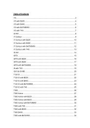
CONTENTS<br />
1. Introduction<br />
2. Unpacking<br />
3. Connectors/Cabling<br />
4. Polarity Checking<br />
5. Amplification & Power Handling<br />
6. Power Selection<br />
7. Equalisation<br />
8. Dimensions<br />
9. Hardware<br />
10. Performance Data<br />
11. Technical Specifications<br />
12. Troubleshooting Guide<br />
13. <strong>i6</strong> Recommended Service Parts & Accessories<br />
14. Warranty<br />
15. Declaration of Conformity
1. Introduction<br />
2. Unpacking<br />
Designed for a wide variety of sound reinforcement applications the <strong>Tannoy</strong><br />
<strong>i6</strong> <strong>AW</strong> <strong>ICT</strong> (All Weather) is an ultra compact loudspeaker system capable of<br />
delivering high sound pressure levels with extremely low distortion, resulting in<br />
outstanding clarity, definition and detail. A truly universal solution, the <strong>i6</strong> <strong>AW</strong> <strong>ICT</strong><br />
offers outstanding durability and resistance to scuffs and knocks. Able to deliver<br />
consistent performance under a wide range of adverse conditions the <strong>i6</strong> <strong>AW</strong> <strong>ICT</strong> is<br />
suited to applications indoors or out, whether it be a theme bar or theme park.<br />
Available in black or white the <strong>i6</strong> <strong>AW</strong> <strong>ICT</strong> will effectively blend into most backgrounds.<br />
Utilisation of the point source <strong>ICT</strong> Drive unit allows the <strong>i6</strong> <strong>AW</strong> <strong>ICT</strong> to be mounted on a<br />
wall or ceiling in either horizontal or vertical orientations without affecting its<br />
performance. A range of hardware options ensures simple and effective installation.<br />
Also available with built in line transformer (<strong>i6</strong>T <strong>AW</strong> <strong>ICT</strong>).<br />
This versatile design has addressed the two most common component failures<br />
experienced in background music and sound reinforcement system installations,<br />
namely the tweeter and the crossover. Due to the revolutionary design of the <strong>ICT</strong><br />
drive unit, neither of these failures can occur, assuring you years of trouble free use.<br />
<strong>ICT</strong> or Inductive Coupling Technology utilises a wireless electromagnetic tweeter<br />
that does not require a crossover and cannot be burned out from heavy or abusive<br />
use. The 1” aluminium high frequency dome has a deep drawn skirt, which sits on the<br />
inside of the low frequency voice coil in the same magnetic gap. The skirt is like a<br />
single shorted turn, which is induced with high frequency information generated by<br />
the low frequency voice coil, which is fed a full bandwidth signal. The <strong>ICT</strong> dome is<br />
at the heart of our 6.5” transducer which utilises a moulded plastic cone and nitryl<br />
rubber surround to further enhance it’s durability and long term reliability.<br />
For applications requiring extended low frequency enhancement, a range of <strong>Tannoy</strong><br />
sub-bass systems are available and can be used in conjunction with the <strong>i6</strong> <strong>AW</strong> <strong>ICT</strong>.<br />
Every <strong>Tannoy</strong> <strong>i6</strong> <strong>AW</strong> <strong>ICT</strong> product is carefully inspected before packing. After<br />
unpacking your loudspeakers, please inspect for any exterior physical damage, and<br />
save the carton and any relevant packaging materials in case the loudspeaker again<br />
requires packing and shipping. In the event that damage has been sustained in<br />
transit notify your dealer immediately.<br />
3. Connectors/Cabling<br />
The <strong>i6</strong><strong>AW</strong> <strong>ICT</strong> is fitted with two 4mm binding posts and a 4-pole Neutrik Speakon' for<br />
connection to the amplifier. These are paralleled within the enclosure.<br />
The two binding post terminals are capable of accepting cables with a conductor of<br />
up to 6mm.<br />
Red is Positive<br />
Black is Negative<br />
Speakon has the following advantages over EP and XLR type connectors: All<br />
terminations are solderless; this makes life easier at the time of installation or when<br />
field servicing is required. Contacts will accept 6 sq. mm wire with an outside<br />
diameter of upto 15mm and a current rating of 30 Amps. The pins of the 2 Speakon<br />
sockets identified input/output on the rear of the input panel are paralleled within the<br />
enclosure. <strong>Tannoy</strong> have adopted the conventional wiring standard for the <strong>i6</strong><strong>AW</strong> <strong>ICT</strong><br />
product:<br />
Pin 1+ is Positive<br />
Pin 1- is Negative<br />
For a worldwide list of Neutrik distributors see http://www.neutrik.com/<br />
Connectors should be wired with a minimum of 2.5 sq. mm (12 gauge) cable. This will<br />
be perfectly satisfactory under normal conditions. In the case of very long cable runs<br />
the wire size should exceed this, refer to the following table for guidance:-
CABLE RUN<br />
(m)<br />
10 2.5<br />
4.0<br />
6.0<br />
25 2.5<br />
4.0<br />
6.0<br />
50 2.5<br />
4.0<br />
6.0<br />
100 2.5<br />
4.0<br />
6.0<br />
C.S.A. OF EACH<br />
CONDUCTOR (mm)<br />
CABLE<br />
RESISTANCE Ω<br />
0.14<br />
0.09<br />
0.06<br />
0.35<br />
0.22<br />
0.14<br />
0.69<br />
0.43<br />
0.29<br />
1.38<br />
0.86<br />
0.58<br />
% POWER LOSS<br />
INTO 8Ω LOAD<br />
1.7<br />
1.1<br />
0.73<br />
4.3<br />
2.7<br />
1.8<br />
8.6<br />
5.4<br />
3.6<br />
17.0<br />
11.0<br />
7.2<br />
% POWER LOSS<br />
INTO 4Ω LOAD<br />
3.5<br />
2.2<br />
1.5<br />
8.6<br />
5.4<br />
3.6<br />
17.0<br />
11.0<br />
7.2<br />
35.0<br />
22.0<br />
14.0<br />
4. Polarity Checking<br />
It is most important to check the polarity of the wiring. A simple method of doing this<br />
without a pulse based polarity checker for LF units is as follows: Connect two wires to<br />
the +ve and -ve terminals of a PP3 battery. Apply the wire which is connected to the<br />
+ve terminal of the battery to the speaker cable leg which you believe to be<br />
connected to the red speaker terminal and likewise the -ve leg of the battery to the<br />
black speaker terminal<br />
If you have wired it correctly the LF drive unit will move forward, indicating the wiring<br />
is correct. All that remains now is to connect the +ve speaker lead to the +ve<br />
terminal on the amplifier and the -ve lead to the -ve terminal on the amplifier. If<br />
however the LF driver moves backwards, the input connections need to be inverted.<br />
If problems are encountered, inspect the cable wiring in the first instance. It should<br />
also be noted that different amplifier manufacturers utilise different pin configurations<br />
and polarity conventions, if you are using amplifiers from more than one<br />
manufacturer, check the polarity at the amplifiers as well as the loudspeakers.<br />
5. Amplification & Power Handling<br />
As with all professional loudspeaker systems, the power handling is a function of<br />
voice coil thermal capacity. Care should be taken to avoid running the amplifier into<br />
clip (clipping is the end result of overdriving any amplifier). Damage to the<br />
loudspeaker will be sustained if the amplifier is driven into clip for any extended<br />
period of time. Headroom of at least 3dB should be allowed. When evaluating an<br />
amplifier, it is important to take into account its behaviour under low impedance load<br />
conditions. A loudspeaker system is highly reactive and with transient signals it can<br />
require more current than the nominal impedance would indicate.<br />
Generally a higher power amplifier running free of distortion will do less damage to<br />
the loudspeaker than a lower power amplifier continually clipping. It is also worth<br />
remembering that a high powered amplifier running at less than 90% of output power<br />
generally sounds a lot better than a lower power amplifier running at 100%. An<br />
amplifier with insufficient drive capability will not allow the full performance of the<br />
loudspeaker to be realised.<br />
It is important when using different manufacturers amplifiers in a single installation<br />
that the have very closely matched gains, the variation should be less than +/- 0.5dB.<br />
This precaution is important to the overall system balance when only a single<br />
compressor/limiter or active crossover is being used with multiple cabinets; it is<br />
therefore recommended that the same amplifiers be used throughout.<br />
6. Power Selection (<strong>i6</strong>T <strong>AW</strong> <strong>ICT</strong>)<br />
Determine the maximum power in watts needed at each speaker location. The <strong>i6</strong> <strong>AW</strong><br />
<strong>ICT</strong> transformer can be tapped at 60w, 30w, 15w, with an extra 7.5W tapping for<br />
70.7V line systems via the rotary switch located on the metal plate at rear of the
loudspeaker. When the relevant tappings have been selected add the individual<br />
wattages required at all speakers and select an amplifier with a rating equal to or<br />
exceeding the total wattage required. All of the transformer primaries should be<br />
connected in parallel to the output of this amplifier. If for example, you select the 30-<br />
watt transformer tap, it means that at full rated amplifier output the speaker will<br />
receive the full 30 watts. If the amplifier gain is reduced each speaker will receive a<br />
proportional amount of power, maintaining the overall system balance.<br />
When calculating amplifier wattage requirements for a system, it is recommended<br />
that a generous wattage safety margin (3dB of headroom) be left so that the system<br />
does not have to operate continuously at its full rated output<br />
7. Equalisation<br />
The <strong>i6</strong><strong>AW</strong> <strong>ICT</strong> loudspeaker is designed to need no equalisation or correction to<br />
overcome system limitations. As a result, it will only need equalisation to compensate<br />
for difficult acoustic environments.<br />
Excess equalisation can reduce system headroom, and introduce phase distortion<br />
resulting in greater problems than it cures. If equalisation is required then it should be<br />
applied gently and smoothly. Violent equalisation will be detrimental to the overall<br />
sound quality. If the loudspeakers were being used consistently at high levels it would<br />
be beneficial to introduce a high-pass filter at 50Hz to protect the loudspeaker from<br />
any unnecessary subsonic frequencies.<br />
8. Dimensions
9. Hardware<br />
The <strong>i6</strong><strong>AW</strong> <strong>ICT</strong> can be wall or ceiling mounted using the MB6 (optional) bracket (fig 1.)<br />
which is designed to offer the maximum flexibility in selecting the desired angles.<br />
The MB6 is supplied with M8 bolts for fixing to the loudspeaker (fig1.& 2). After fixing<br />
the bracket to the wall or ceiling remove the plastic plugs from the top and bottom of<br />
the loudspeaker. Position the cabinet at the required angle as shown and tighten the<br />
M8 Bolts to fix the loudspeaker in position.<br />
The loudspeaker can be mounted either horizontally or vertically using the MB6<br />
bracket (fig1.& 2.). This product has four M6 threaded holes in the rear of the cabinet<br />
for other bracketry.<br />
Fig 1.<br />
Fig 2.<br />
NOTE: The installation of this product<br />
must be carried out in conformity with<br />
local building codes and standards. If<br />
necessary consult your local safety<br />
standards officer before installing any<br />
product. Alternatively, check any laws<br />
or bylaws.<strong>Tannoy</strong> will not be held<br />
responsible for any damages caused<br />
by the improper installation of any<br />
bracket or loudspeaker.<br />
Fig 3.
10. Performance Data<br />
Anechoic Frequency Response, 1watt @ 1m<br />
Impedance
11. Technical Specifications<br />
Frequency response (1) +/- 3dB<br />
Recommended Amplifier Power<br />
Power Handling<br />
60Hz - 20kHz<br />
up to 120 watt / 4 ohm<br />
Average(2) Programme Peak (10ms)<br />
60 watt 120 watt 240 watt<br />
Sensitivity (1)<br />
2.83 volt @ 1m 89dB 92dB (half space)<br />
Maximum SPL (3) Average Peak<br />
@ 1m 107dB 113dB<br />
Transformer (<strong>i6</strong>T <strong>AW</strong> <strong>ICT</strong>) Max. Insertion loss 0.9 dB 35Hz – 21kHz +/- 2dB<br />
Primary Taps 60,30,15, 7.5* watt<br />
Voltage Taps 70.7V & 100V<br />
Impedance Nominal 8 ohm<br />
Driver Complement<br />
Crossover Point<br />
Enclosure<br />
Finish<br />
Protective Grille<br />
Connectors<br />
Fittings<br />
Dimensions<br />
Weight<br />
Shipping Dimensions<br />
6.5” (165mm) full range <strong>ICT</strong> Point Source<br />
7 kHz inductively coupled<br />
11 litre, vented polyethylene<br />
Black/Grey or White<br />
Perforated Aluminium<br />
2 x 4mm 5way binding posts<br />
1 x NL4 speakon<br />
2 x M8 inserts for Yolk Bracket<br />
4 x M6 inserts on rear of cabinet<br />
344mm (H) x 250mm (W) x 225mm (D)<br />
13.54” (H) x 9.84” (W) x 8.86” (D)<br />
3.7 Kg (8.1 lbs)<br />
400mm (H) x 500mm (W) x 300mm (D)<br />
15.75” (H) x 19.69” (W) x 11.8” (D)<br />
NOTES:<br />
(1) Average over stated bandwidth. Measured at 1m on axis, in an anechoic chamber.<br />
(2) Long term power handling capacity as defined in EIA standard RS - 426A.<br />
(3) Unweighted pink noise input, measured at 1m<br />
<strong>Tannoy</strong> operates a policy of continuous research and development. The introduction of new materials or manufacturing methods will always equal<br />
or exceed the published specifications which <strong>Tannoy</strong> reserve the right to alter without prior notice.<br />
Please verify the latest specifications when dealing with critical applications.
12. Troubleshooting Guide<br />
Symptom Possible Cause Action<br />
No Output From Speakers Broken Speaker Cables(s)<br />
Amplifier<br />
Check the electrical continuity of<br />
the loudspeaker cables, and<br />
replace if necessary.<br />
Check the gain controls on the<br />
amplifier are turned up.<br />
Be sure the amplifier is receiving<br />
an input signal (check the<br />
“signal” indicators on the amp).<br />
Connect the loudspeaker cable<br />
which has no output to another<br />
amplifier channel you know is<br />
working, make sure signal is fed<br />
to the new amplifier channel. If<br />
output is obtained from the<br />
loudspeakers(s) then the<br />
problem is with the amplifier<br />
channel or input signal leads. If<br />
this is not the case then the fault<br />
may lie in the cabling or the<br />
loudspeaker.<br />
Intermittent Output Poor Connection Check the loudspeaker cabling<br />
has a good electrical connection<br />
with amplifier outputs and<br />
loudspeaker inputs. A bad<br />
connection can increase<br />
resistance which will<br />
substantially reduce the output,<br />
or make “cracking” noises which<br />
are unrelated to signal content<br />
Poor Low Frequency<br />
Output<br />
Irregular sounds such as<br />
buzzing and humming<br />
emanating from the<br />
loudspeaker<br />
“Out of phase” connection<br />
Poor system grounding<br />
Faulty electronic device in<br />
the signal chain<br />
If using multi-strand loudspeaker<br />
cable, be sure no strands of<br />
cable are causing short circuits<br />
between the positive and<br />
negative terminals of the<br />
amplifier outputs and/or<br />
loudspeaker inputs.<br />
When two speakers are<br />
connected “out of phase”, the low<br />
frequencies will virtually be<br />
cancelled out. Check the<br />
connections at the<br />
amplifier/speaker paying<br />
attention to polarity. (see section<br />
4).<br />
Check and correct system<br />
grounding.<br />
The speaker cannot generate<br />
these sounds on its own. It is<br />
most likely there is a fault with a<br />
piece of electronic equipment in<br />
the signal path.
13. I6 <strong>AW</strong> <strong>ICT</strong> Service Parts & Accessories<br />
Part Number Description<br />
7900 0593 Driver Kit – 6.5” <strong>ICT</strong><br />
14. Warranty<br />
No maintenance of the <strong>i6</strong> <strong>AW</strong> <strong>ICT</strong> loudspeaker is necessary.<br />
All <strong>Tannoy</strong> professional loudspeaker products are covered by a 5 year warranty from<br />
the date of manufacture subject to the absence of misuse, overload or accidental<br />
damage. Claims will not be considered is the serial number has been altered or<br />
removed. Work under warranty should only be carried out by a <strong>Tannoy</strong> Professional<br />
dealer or service agent. This warranty in no way affects your statutory rights. For<br />
further information please contact your dealer or distributor in your country. If you<br />
cannot locate your distributor please contact Customer Services, <strong>Tannoy</strong> Ltd at the<br />
address given below.<br />
Customer Services<br />
<strong>Tannoy</strong> Ltd.<br />
Rosehall Industrial Estate<br />
Coatbridge<br />
Strathclyde<br />
ML5 4TF<br />
Scotland<br />
Telephone: 01236 420199 (National)<br />
+44 1236 420199 (International)<br />
Fax: 01236 428230 (National)<br />
+44 1236 428230 (International)<br />
E-Mail: prosales@tannoy.com<br />
DO NOT SHIP ANY PRODUCT TO TANNOY WITHOUT PREVIOUS AUTHORISATION<br />
Our policy commits us to incorporating improvements to our products through<br />
continuous research and development. Please confirm current specifications for<br />
critical applications with your supplier.<br />
EASE Data for <strong>Tannoy</strong> Professional products available on request.
Declaration of Conformity<br />
The following apparatus is/are manufactured in the United Kingdom by <strong>Tannoy</strong> Ltd of<br />
Rosehall Industrial estate, Coatbridge, Scotland, ML5 4TF and conform(s) to the<br />
protection requirements of the European Electromagnetic Compatibility Standards<br />
and Directives relevant to Domestic Electrical Equipment. The apparatus is designed<br />
and constructed such that electromagnetic disturbances generated do not exceed<br />
levels allowing radio and telecommunications equipment and other apparatus to<br />
operate as intended, and, the apparatus has an adequate level of intrinsic immunity<br />
to electromagnetic disturbance to enable operation as specified and intended.<br />
Details of the Apparatus:<br />
Associated Technical File:<br />
Applicable Standards:<br />
<strong>Tannoy</strong> Contractor Loudspeaker<br />
Model Number: <strong>i6</strong><strong>AW</strong> iCT<br />
EMC<strong>i6</strong><strong>AW</strong><strong>ICT</strong><br />
EN 55103-1 Emission<br />
EN 55103-2 Immunity<br />
EN60065 Electrical Safety<br />
Signed:<br />
Position:<br />
Engineering Director<br />
<strong>Tannoy</strong> Commercial<br />
Date: 5 th Oct 2004<br />
For <strong>Tannoy</strong> Ltd
<strong>Tannoy</strong> Loudspeakers are manufactured<br />
in Great Britain by :<br />
<strong>Tannoy</strong> Ltd, Rosehall Industrial Estate, Coatbridge,<br />
Strathclyde, ML5 4TF, SCOTLAND<br />
Telephone: +44 (0)1236 420199 Fax: +44 (0)1236 428230<br />
<strong>Tannoy</strong> North America Inc, Suite 1. 335 Gage Avenue, Kitchener, Ontario, CANADA, N2M 5E1<br />
Telephone: (519) 745 1158 Fax: (519) 745 2364<br />
Issue 1.0 Part No. 6481 0435<br />
GH Oct5th, 2004