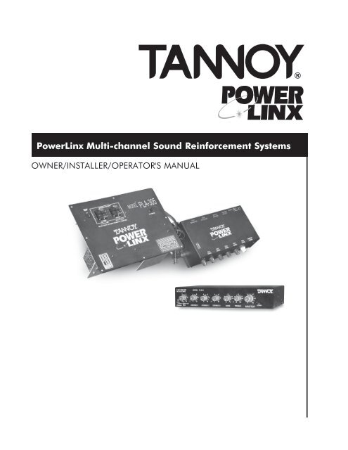
PowerLinx Multi-channel Sound Reinforcement Systems - Tannoy
PowerLinx Multi-channel Sound Reinforcement Systems - Tannoy
PowerLinx Multi-channel Sound Reinforcement Systems - Tannoy

You also want an ePaper? Increase the reach of your titles
YUMPU automatically turns print PDFs into web optimized ePapers that Google loves.
{<br />
<strong>PowerLinx</strong> <strong>Multi</strong>-<strong>channel</strong> <strong>Sound</strong> <strong>Reinforcement</strong> <strong>Systems</strong><br />
OWNER/INSTALLER/OPERATOR'S MANUAL
WARRANTY/DAMAGE CLAIMS<br />
{<br />
2<br />
All <strong>Tannoy</strong> professional loudspeaker products are covered by a 5 year warranty for loudspeaker components and<br />
one year for electronic components from the date of purchase subject to the absence of misuse, overload,<br />
or accidental damage.<br />
Claims will not be considered if the serial number has been altered or removed.<br />
Work under warranty should only be carried out by a <strong>Tannoy</strong> Professional dealer or service agent.<br />
This warranty in no way affects your statutory rights.<br />
For further information please contact your service dealer or distributor in your area. If you cannot locate a distributor,<br />
please contact Customer Services, <strong>Tannoy</strong> North America Inc. at the address given below.<br />
DO NOT SHIP ANY PRODUCT TO TANNOY WITHOUT PRIOR AUTHORIZATION.<br />
Our policy commits us to incorporating improvements to our products through continuous research and development.<br />
Please confirm current specifications for critical applications with your supplier.<br />
<strong>Tannoy</strong> North America Inc.<br />
335 Gage Ave., Suite #1<br />
Kitchener, ONTARIO CANADA<br />
N2M 5E1<br />
Tel: (519) 745-1158 } FAX: (519) 745-2364 } Toll Free Dealer Faxline: (800) 525-7081<br />
Email: inquiries@tannoyna.com } www.tannoy.com } www.tannoyna.com<br />
For further information on our warranty policies,please refer to our website.<br />
Our customer service dept. is available during normal office hours (EST) for questions regarding service, purchase,<br />
installation or any other technical matters.<br />
Installation of <strong>Tannoy</strong> products should be performed by an experienced contractor familiar with local<br />
codes. Failure to properly install and secure heavy <strong>Tannoy</strong> equipment may cause a device to fall.<br />
<strong>Tannoy</strong> cannot be responsible for damage or injury due to improperly installed equipment.<br />
UNPACKING-DAMAGE CLAIMS<br />
Each <strong>Tannoy</strong> product is inspected for damage and inventoried to insure that all accessories and packing materials are<br />
included before sealing and shipping.<br />
When unpacking equipment, take note of any damages to the cardboard container and carefully inspect your <strong>Tannoy</strong><br />
equipment for any impact in that area. Should you have any damage, immediately notify your carrier and our <strong>Tannoy</strong><br />
customer service dept. A return claim may be issued. You may be required to repack the equipment for pick-up by<br />
your local carrier.
TABLE OF CONTENTS<br />
{<br />
3<br />
WARRANTY/DAMAGE CLAIMS/UNPACKING<br />
CONTENTS<br />
INTRODUCTION<br />
PLA305 5-Channel Amplifier<br />
PLC4.1 Controller<br />
PLM-4 Mixer w/Ducking<br />
REMOTE LEVEL CONTROL<br />
Wall-mount Potentiometer<br />
PRODUCTS<br />
PLA305 5-Channel Amplifier<br />
PLC4.1 Controller<br />
Description of Controls<br />
Set-Up and Testing<br />
System Commissioning w/remote<br />
PLM-4 4-Channel Mixer/Preamplifier<br />
Description of Controls<br />
Installation and Set-Up<br />
Technical Specifications<br />
REMOTE LEVEL CONTROL<br />
Wall-mount Potentiometer, Wiring<br />
2<br />
3<br />
4<br />
4<br />
4<br />
4<br />
5<br />
6<br />
7<br />
8<br />
9<br />
10<br />
11,12<br />
13<br />
14<br />
15
INTRODUCTION<br />
{<br />
4<br />
PLA305 5-Channel Power Amplifier<br />
Designed to mount directly into the cutout provided on one of our 110 series<br />
subwoofers,the PLA305 is a powerful and versatile center of your multi-<strong>channel</strong><br />
sound reinforcement system. The 5 amplifiers (100 watts for the sub, 50 watts<br />
each for the 4 full-range outputs) use ProBASH technology for great sound and<br />
superb efficiency. ProBASH circuits track the audio waveform and provide a<br />
dynamic DC voltage,on demand, to the class AB amplification stages. An auto-power<br />
feature switches power on or off in response to the audio signal.<br />
PLC4.1 Controller<br />
Mounted directly to PLA305 amplifier , the PLC4.1 Controller is the control center<br />
for audio signal pre-amplification, balancing, distribution and filtering. For a full<br />
description of its flexibility and use , see the PRODUCT section of this manual.<br />
Master remote volume control is possible with our remote control options (see the<br />
REMOTE section of this manual). Individual <strong>channel</strong> remote volume control is<br />
enabled with the installation of our VCA card (see your <strong>Tannoy</strong> dealer).<br />
PLM-4 Mixer with Ducking<br />
The PLM-4 has all the inputs needed for most commercial applications. It is<br />
designed to provide a properly mixed and pre-amplified balanced audio feed to<br />
the PLC4.1 Controller via a long-wire run. Power supply is by a 12V DC wall-wart.<br />
For a complete description of its controls and functions, see the PRODUCT section<br />
of this manual.<br />
REMOTE VOLUME CONTROL<br />
NOTE: Overall master volume control is a standard function of the PLC4.1. Remote control of<br />
individual <strong>channel</strong>s requires the factory installed VCA card.<br />
1) Wall-mount Potentiometer (25K ohm). Each multi-<strong>channel</strong> amplifier is shipped<br />
with one standard wall mount potentiometer.<br />
Simple 3-wire connection to the PLC4.1.
POWERLINX PRODUCTS<br />
{<br />
5<br />
PLA305 5-Channel Power Amplifier<br />
The PLA305 amplifier resides in the 110 series subwoofer cabinet. All internal woofer connections are made for<br />
you at the factory. Four external 50 watt full-range speaker connector sets are accessible on the front panel of the PLA305.<br />
1<br />
2<br />
3<br />
1) PREAMP INPUT<br />
Accepts the supplied 30 cable from the PLC4.1. Audio signals from and power to the PLC4.1 are routed via this<br />
cable. Note that the PLC4.1 module may be temporarily located remotely, with the 12 cable option,<br />
to facilitate system set-up<br />
2) SPEAKER OUTPUTS<br />
Four separate 50 watt speaker-level outputs are provided. Each output should be limited to a minimum of 3 ohms<br />
speaker load. Wire connections are made via spring-loaded push-and-release connectors (maximum wire size; 14<br />
gauge). Your choice of plenum-rated speaker wire should be made with consideration for length of run and damping<br />
characteristics. Be sure to observe consistent phasing of your full-range speakers and avoid shorting of<br />
speaker wires.<br />
3) POWER CORD<br />
110VAC 60 Hz 5A. A standard 2-prong plug is provided. There is no power switch on the PLA305. Automatic power<br />
on/off is made in the presence or absence of an audio signal.
POWERLINX PRODUCTS<br />
{<br />
6<br />
PLC4.1 Controller<br />
The PLC4.1 Controller is designed to mount directly to the face the PLA305 amplifier panel. However, a 12<br />
interconnect cable is available from your <strong>Tannoy</strong> dealer if a remote set-up of the PLC4.1 is required. All controls and<br />
connectors on the PLA305 and PLC4.1 are accessible when the controller is mounted to the amplifier.<br />
The PLC4.1 is ideally suited to receive a 2-<strong>channel</strong>, pre-amplified audio signal from the PLM-4 or other signal source via<br />
a balanced wire run (Belden 8451, or equivalent). Each input may be commissioned to any combination of the 4 outputs.<br />
REMOTE VOLUME (VCA)<br />
(OPTIONAL)<br />
STEREO SOURCE<br />
LINE LEVEL<br />
PLC 4.1<br />
110 SUB<br />
W/S1-341<br />
AMPLIFIER<br />
FULL-RANGE<br />
SPEAKERS<br />
SUB-LOOP OUT<br />
(LINE LEVEL)<br />
ACTIVE<br />
110 SUB<br />
2nd ZONE<br />
SUBWOOFER<br />
Additional features of the PLC4.1 include:<br />
} Switchable high-pass filtering for any output.<br />
} Individual volume control for each speaker output (the subwoofer and SUB LOOP<br />
OUTPUT volume share one control).<br />
} VCA interfacing for remote master volume control. <strong>Multi</strong>-<strong>channel</strong> remote volume control is possible when our<br />
optional VCA card is installed.<br />
The following configurations are typical of the many systems possible with Power Linx:<br />
} Subwoofer and four mono <strong>channel</strong>s<br />
} Subwoofer and two stereo pairs<br />
} Subwoofer, stereo pair, and two mono <strong>channel</strong>s<br />
} Two subwoofers and two stereo pairs<br />
} Full-range sub-line out, sending to a second similar system, effectively doubling the capabilities listed above.<br />
Note that it is not necessary to use all four <strong>channel</strong>s. Any speaker level output may be left unused.<br />
Additionally, more than one speaker may be connected to each output and each <strong>channel</strong> can handle<br />
loads down to 3 ohms.
POWERLINX PLC4.1 CONTROLLER<br />
{<br />
7<br />
Description of Controls<br />
5<br />
Rear<br />
6<br />
SUB 1 2 3 4<br />
L R L R L R L R L R<br />
OUT<br />
UP = Full Frequency<br />
+10V MR<br />
SUB 1 2 3 4<br />
1 2 3 4 5 6 7 8 910 IN<br />
L = Left Input<br />
R = Right Input<br />
1 2 3 4<br />
DOWN = 80Hz Hi-Pass<br />
Side<br />
LINE LEVEL ONLY<br />
LEFT<br />
INPUT<br />
RIGHT<br />
INPUT<br />
SUB LOOP<br />
OUT<br />
4<br />
Front<br />
7<br />
+ + +<br />
8 9<br />
1<br />
2<br />
3<br />
1) CH1 through CH4 LEVEL Adjusts the level of each of 4 full range outputs which arerouted to the PLA305 amplifier.<br />
2) SUB-LEVEL Adjusts the level of the subwoofer amplifier output, as well as the level of the sub-loop output<br />
3) MASTER LEVEL Adjusts the overall level of all 5-speak er level outputs to the PLA305 amplifier, including<br />
the line level output.<br />
4) VCA MASTER Connections for use of a remote volume control. (See REMOTE.)<br />
5) VCA RETURNS Individual <strong>channel</strong> connections for remote volume control when the optional VCA card is installed.<br />
See your <strong>Tannoy</strong> dealer. (See REMOTE.)<br />
6) INPUT MATRIX Assigns either left, right, both or neither of the two inputs to any of the five outputs. DIP switches<br />
are used to switch the left or right signals IN or OUT for each <strong>channel</strong>. EXAMPLE: To enable both left and right inputs<br />
to sum together for the subwoofer, switch DIP sw#1 and #2 to the down (IN) position. If any output is not to be used,<br />
its 2 switches may be set up to the OUT position.<br />
7) FILTER SELECT Allows selection of an 80 Hz high-pass filter to be added to any combination of the 4 outputs,<br />
thereby reducing low frequency content in the selected <strong>channel</strong>s.<br />
8) LEFT and RIGHT INPUTS Balanced line-level inputs on the PLC4.1 Controller. Wire termination via Phoenix<br />
connectors for tinned, bare wire leads, 18-24 gauge.<br />
9) SUB LOOP OUT A line-level, full bandwidth balanced output for use with a second subwoofer or full range system.<br />
Level control of this output is in concert with the SUB and MASTER levels..
POWERLINX PLC4.1 CONTROLLER<br />
{<br />
8<br />
Set-Up and Testing<br />
Before applying power to the system, insure that all audio connections are properly<br />
terminated and all level controls including the control room feeds are set to minimum.<br />
Once your system is fully wired to a sound source and speakers, a careful balancing of all levels is necessary to provide<br />
pleasing sound levels, adequate audio headroom, and system protection from excessive volume or overdriving.<br />
System Commisioning Procedure-<br />
Unless fitted with a remote volume control, all level adjustments (excepting the control room feeds) are performed on<br />
the PLC4.1 Controller.<br />
1) Set all level controls to minimum. Remove security covers and set all FILTER SELECT switches to FULL FREQUENCY.<br />
2) Plug the PLA4.1 into a 110vac wall output.<br />
3) Set MASTER LEVEL control to mid position.<br />
4) Start the music source and adjust audio feeds to mid position.<br />
5) Adjust CH 1 through CH 4 LEVEL controls to their desired operating levels. If satisfactory levels cannot be<br />
achieved, increase the MASTER LEVEL control and readjust the <strong>channel</strong> levels if necessary.<br />
6) Switch FILTER SELECT switches to their DOWN position (80 Hz high-pass) for those speakers that will be used<br />
in conjunction with a subwoofer, or cannot reproduce frequencies below 80 Hz.<br />
7) Adjust the SUB LEVEL control until the subwoofer level is balanced with its main speakers.<br />
Note that the use of high-pass filters will increase the overall system headroom by several dB.<br />
8) Once all levels are satisfactory, reinstall the security covers on the PLC4.1.
POWERLINX PLC4.1 CONTROLLER<br />
{ 9<br />
System Commisioning for Remote Volume Controls Procedure-<br />
<strong>Systems</strong> fitted with wall mount volume control require careful commissioning to ensure that safe levels cannot be<br />
exceeded at any wall control panel. The optional remote controls can only attenuate levels downward from the maximum<br />
levels set on the PLC4.1 Controller .<br />
1) Set all level controls on the PLC4.1 to minimum.<br />
2) Set wall panel control(s) to minimum.<br />
3) Set all FILTER SELECT switches to FULL FREQUENCY.<br />
4) Plug the PLA305 amplifier into a 110vac wall outlet.<br />
5) Set all wall panel controls to maximum.<br />
6) Adjust sub level and master level wall panel controls to maximum.<br />
7) Adjust MASTER LEVEL control to its mid position.<br />
8) Select a <strong>channel</strong> (or zone) where the highest sound levels will be required.<br />
9) Start the music source. Feed levels should be at mid position.<br />
10) Carefully adjust the selected <strong>channel</strong>'s LEVEL control to the desired maximum safe level. If an adequate level<br />
cannot be achieved, check the signal source level and readjust if necessary .<br />
11) If an adequate level still cannot be achieved, raise the MASTER LEVEL to a higher position. Readjust the <strong>channel</strong><br />
LEVEL to achieve the desired volume.<br />
12) Set the three remaining <strong>channel</strong> LEVEL controls to their appropriate levels without adjusting the<br />
MASTER LEVEL control.<br />
13) Once the levels on the PLC4.1 have been set, all operator level changes will be made at the remote wall<br />
control panel.<br />
14) Switch FILTER SELECT switches to their DOWN position as required.<br />
15) Adjust the SUB LEVEL control for a subwoofer sound level that is complementary with its associated main speakers.<br />
16) Reinstall the security covers on the PLC4.1.
PLM-4 4 CHANNEL MIXER/PREAMPLIFIER with DUCKING<br />
{<br />
10<br />
Designed as the input control center for your music system, or a stand-alone mixer, the free-standing PLM-4 is usually<br />
installed remotely in a control room and interfaced to the PLC4.1 Controller by a long-wire run, either balanced XLR to<br />
the PLC4.1B (recommended for lowest noise) or unbalanced RCA to a PLC4.1. Low current power is provided by a<br />
supplied 12VDC wall wart. Additional PLM-4s may be link ed for more inputs.<br />
Some of the many features of the PLM-4 include:<br />
} A balanced XLR microphone input<br />
} Three RCA stereo line inputs<br />
} Balanced (XLR) and unbalanced (RCA) outputs<br />
} Three position ducking (mic-over-music) switch: Mute/Dim/None<br />
} Independent volume for all the input sources<br />
} Up to 3 PLM-4s may be linked together for more inputs<br />
} Master Volume, Bass, and Treble controls<br />
} Ground lift switch<br />
} Half rack size<br />
} Operates anywhere on 9 to 15 volts, DC or AC. Supplied wall wart supply.
POWERLINX PLM-4 MIXER/PREAMPLIFIER<br />
{<br />
11<br />
Description of Controls<br />
-<br />
MODEL<br />
PLM-4 MIXER<br />
-<br />
2<br />
4<br />
6<br />
8<br />
2<br />
4<br />
6<br />
8<br />
2<br />
4<br />
6<br />
8<br />
2<br />
4<br />
6<br />
8<br />
-3<br />
-6<br />
0<br />
+3 -3<br />
+6 -6<br />
0<br />
+3<br />
+6<br />
2<br />
4<br />
6<br />
8<br />
1<br />
0 10 0 10<br />
SENS.<br />
MUTE NONE DIM<br />
DUCKING<br />
0 10<br />
0 10<br />
-12 +12 -12 +12 0 10<br />
MIC STEREO 1 STEREO 2 STEREO 3 BASS TREBLE MASTER<br />
POWER<br />
2 3 4<br />
5 6 7<br />
1) SENSITIVITY TRIM (SENS.) Sets the microphone trigger level when DIM or MUTE is selected.<br />
2) DUCKING This switch selects one of three options that determine how microphone announcements<br />
affect the music level:<br />
NONE - No ducking<br />
DIM - Automatic 10 dB music level reduction while speaking into the microphone.<br />
MUTE - Automatically shuts the music off when speaking into the microphone.<br />
3) MIC Adjusts the microphone level (equally distributed between left and right outputs).<br />
Ducking does not affect this level.<br />
4) STEREO 1 STEREO 3 Adjusts the level of the STEREO RCA inputs. These inputs are suitable for CD players,<br />
tuners, TVs, VCR audio, etc.<br />
5) BASS Over all adjustment of low frequency levels.<br />
6) TREBLE Over all adjustment of high frequency levels.<br />
7) MASTER Adjusts overall level of all the mixed audio sources. Adjust to provide a suitable signal level to<br />
the PLC4.1 controller or other following amplifier. Unity gain of the mixer is provided when STEREO input<br />
and MASTER output levels are at 12 o'clock.
{<br />
12<br />
POWERLINX PLM-4 MIXER/PREAMPLIFIER<br />
Description of Controls<br />
4<br />
3<br />
1<br />
6<br />
5<br />
ON<br />
OFF<br />
LIFT<br />
GND<br />
OUT<br />
LINK<br />
IN<br />
LEFT RIGHT LINE 3 LINE 2 LINE 1 MIC<br />
L<br />
L<br />
L<br />
R<br />
R<br />
R<br />
2<br />
+<br />
9 - 15V AC/DC 1OOmA<br />
OUTPUTS<br />
INPUTS<br />
1) LINE 1 - 3 INPUTS Stereo, line-level RCA inputs for tape decks, CD players, tuners, etc.<br />
2) MICROPHONE (MIC) INPUT Balanced XLR connector suitable for almost any kind of microphone, balanced<br />
or unbalanced. The microphone signal is evenly distributed to the left and right outputs. Pin-out is: 1 (GND), 2 (HI), 3 (LO).<br />
3) OUTPUTS The PLM-4 offers both unbalanced RCA connectors for short wire runs to other unbalanced equipment<br />
and balanced XLR output connectors for longer wire runs to other balanced input devices such as the PLC4.1.<br />
Both outputs may be used simultaneously if required. XLR pin-out is: 1 (GND), 2 (HI), 3 (LO).<br />
4) LINK CONNECTORS Up to 3 PLM-4s may be daisy chained using 5-pin DIN cables via the LINK IN<br />
and OUT connectors.<br />
Connect the LINK OUT of the master unit to the LINK IN of the #2 unit. Connect the LINK OUT of the #2 unit to<br />
the LINK IN of the #3 unit.<br />
Note the following when interconnecting PLM-4s:<br />
} Up to 9 stereo line inputs and up to 3 microphone inputs are possible.<br />
} Power need be connected only to the master unit.<br />
} BASS and TREBLE controls affect inputs on that unit only .<br />
} The MASTER level on the master unit affects all inputs.<br />
} MASTER levels on units #2 and #3 should be set and retained (5 to 7 recommended).<br />
} The DUCKING switch and SENS. trim govern the ducking function on that unit only.<br />
However:<br />
} If a microphone signal is high enough to trigger ducking, at any unit, all sources to all units will be ducked<br />
or muted at the main output of the master unit.<br />
5) ON/OFF SWITCH This switch is located on the rear panel to prevent accidental switching.<br />
6) GROUND (GND) LIFT SWITCH This switch isolates the signal grounds from the chassis and is switched<br />
for least hum or buzz in the output. Note that hum or buzz may have many other possible causes.<br />
7) POWER SOCKET Receives the plug from the supplied 12VDC power supply. Any AC or DC voltage supply<br />
may be used. Power requirements are 9 to 15Vac or DC >100ma.
POWERLINX PLM-4 MIXER/PREAMPLIFIER<br />
{<br />
13<br />
Installation<br />
Before applying power to the system, insure that all audio connections are properly<br />
terminated and all level controls are set to minimum.<br />
For optimum performance, the PLM-4 should be connected to the <strong>PowerLinx</strong> controller through its balanced XLR output<br />
to the controller's balanced Phoenix-type inputs (Belden 82761 or equivalent). As a stand-alone unit the PLM-4 may be<br />
connected to the balanced or unbalanced input of an audio system amplifier.<br />
A microphone with an on/off switch is recommended so it can be left in the "Off" position when not in use for<br />
announcements. In this way, background noise in the vicinity of the microphone won't be heard through the system and<br />
won't trigger the ducking feature. To a void feedback, be sure not to place your microphone too close to your audio system's<br />
loudspeakers, and use shielded cables for all audio connections.<br />
SET-UP<br />
1) Plug the AC adaptor into the +9-15V AC/DC input on the rear of the PLM-4 and then into a power outlet.<br />
Turn on the power to the PLM-4 and your other equipment.<br />
2) Set the MASTER control to about mid position.<br />
3) Adjust the STEREO 1, 2, and 3 level controls on the PLM-4 for your music playback source(s) to comfortable<br />
listening levels.<br />
4) Set your MIC level control to a suitable level for announcements.<br />
5) Select your preferred ducking setting. The three-position DUCKING switch is located below the microphone<br />
level control. You can select "NONE" for no ducking, "DIM" for an automatic 10 dB level reduction of the back<br />
ground music while speaking into the microphone , or "MUTE" to shut the music off completely while you're<br />
speaking into the microphone. .<br />
6) If you chose DIM or MUTE, adjust the SENS. trim with a small screwdriver. Set it so that speaking into the<br />
microphone in a normal voice triggers ducking , but whispering or rustling papers nearby doesn't. Now if you<br />
wish to make an announcement, the background music volume will be reduced while you speak, and will<br />
automatically increase to its previous level after the announcement ends.<br />
7) The MASTER level control should now be adjusted to provide a suitable level to your PLC4.1 or other following<br />
audio equipment. This level should be as high as possible for best noise characteristics but not so high as to<br />
overdrive the following inputs. Usually a position of 5 to 7 is optimum.<br />
8) If any hum or buzz is noted in your audio systems output, try switching the GND LIFT switch. Note that ground<br />
loops or other interferences may occur at any point in the chain of your equipment.<br />
Since the PLM-4 is an end-user adjustable device , the mix may be readjusted at any time. However the MASTER setting<br />
should be carefully made and retained as it has a direct effect on the headroom, audio quality , and system protection of<br />
the PLA305 and its associated loudspeakers.
POWERLINX PLM-4 MIXER/PREAMPLIFIER<br />
{<br />
14<br />
Technical Specifications<br />
INPUTS:<br />
} 3X Stereo line, 5k ohms RCA. Maximum input level: +30 dBu<br />
} 1X Balanced XLR Mic input, 2k ohms. Maximum input level:+1 dBu. Maximum gain to unbalanced output:<br />
75 dB. XLR pin-out is: 1 (GND), 2 (HI), 3 (LO).<br />
MAXIMUM GAIN:<br />
} 30 dB at output, all levels at maximum.<br />
} Unity gain when input and MASTER controls are at 50% rotation.<br />
EQUIVALENT INPUT NOISE:<br />
} -126 dBu, unweighted 20 Hz to 20 kHz.<br />
OUTPUTS:<br />
} Impedance: 100 ohms, unbalanced. 200 ohms, balanced.<br />
} Maximum output level: +19 dBu, unbalanced. +25 dBu, balanced.<br />
} Recommended load impedance: >2.5k ohms. Lesser impedance loads will be tolerated but maximum output<br />
levels will be reduced.<br />
} Connectors: RCA (unbalanced). XLR (balanced) +6 dB over RCA levels.<br />
XLR Pin-out:1 (GND), 2 (HI), 3 (LO).<br />
LINKS (for more PLM-4s) via 5-pin DIN<br />
GENERAL:<br />
} Frequency response: +0, -1 dB from 20 Hz to 20 kHz.<br />
} Output noise:< -80 dBu from 20 Hz to 20 kHz with input and MASTER controls at 12 o'clock and inputs shorted.<br />
} Distortion: < .02% THD at maximum rated output.<br />
} Equalization: Bass +/-14 dB @ 40 Hz. Treble +/- 14 dB @ 18 kHz.<br />
} Dimensions: 1.73 H x 8.56 W x 5 D. Rack mountable with kit from <strong>Tannoy</strong>. Painted steel chassis.<br />
} Power requirement: 12VDC, 100ma at 4 watts. Adaptor supplied. A 230V AC adaptor is also available.
REMOTE LEVEL CONTROL<br />
{<br />
15<br />
25K Linear Potentiometer<br />
All PLC4.1 Controllers will accept this option for remote control of over all (master) volume control. The potentiometer is<br />
typically installed in a single-gang electrical box with a blank cover panel drilled to accept the control. Simple 3-wire<br />
22ga, or equivalent, interconnection. Wiring is as follows:<br />
Rear<br />
of Pot<br />
PLC4.1 <strong>PowerLinx</strong> Controller<br />
+ Voltage<br />
Master Return<br />
Ground<br />
+ 10V<br />
Master Return<br />
Ground<br />
25K Linear Potentiometer (For PLC4.1 w/factory-installed VCA card option)<br />
Individual <strong>channel</strong> (1, 2, 3, 4 and/or SUB) remote volume control is possible with the factory-option VCA card. (See your<br />
<strong>Tannoy</strong> dealer). One or more potentiometers may control any PLC4.1 output(s) in any combination. This is achieved by<br />
wiring the Master Return connection from the potentiometer(s) to the VCA RETURNS connector (one or more pins) for<br />
the <strong>channel</strong>(s) you wish to control.<br />
EXAMPLE: Channels 1 and 2 are feeding a stereo signal to zone #1 you wish to control. Channel 3 is feeding a mono<br />
signal to zone #2 you wish to control separately. Wire the Master Return connection from zone #1's potentiometer to<br />
VCA RETURN 1 and 2 connector pins. Wire the Master Return connection from zone #2's potentiometer to the<br />
VCA RETURN 3 connector pin. The + 10V and GROUND connections are common to all used potentiometers.<br />
ZONE #1<br />
ZONE #2<br />
PLC4.1 <strong>PowerLinx</strong> Controller<br />
Rear<br />
of Pot<br />
Rear<br />
of Pot<br />
+10V MR<br />
Channels<br />
1 2 3 4 Sub<br />
To +10V<br />
To Channel 3<br />
To Ground<br />
To Channels 1 & 2
{<br />
<strong>Tannoy</strong> North America Inc. 335 Gage Avenue, Suite #1 Kitchener, Ontario Canada N2M 5E1<br />
Tel: 519-745-1158 Fax: 519-745-2364 E-mail: inquiries@tannoyna.com<br />
www.tannoy.com<br />
MC-I180703