PowerLinx Multi-channel Sound Reinforcement Systems - Tannoy
PowerLinx Multi-channel Sound Reinforcement Systems - Tannoy
PowerLinx Multi-channel Sound Reinforcement Systems - Tannoy

You also want an ePaper? Increase the reach of your titles
YUMPU automatically turns print PDFs into web optimized ePapers that Google loves.
{<br />
12<br />
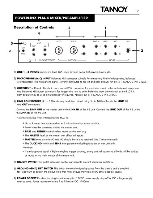
POWERLINX PLM-4 MIXER/PREAMPLIFIER<br />
Description of Controls<br />
4<br />
3<br />
1<br />
6<br />
5<br />
ON<br />
OFF<br />
LIFT<br />
GND<br />
OUT<br />
LINK<br />
IN<br />
LEFT RIGHT LINE 3 LINE 2 LINE 1 MIC<br />
L<br />
L<br />
L<br />
R<br />
R<br />
R<br />
2<br />
+<br />
9 - 15V AC/DC 1OOmA<br />
OUTPUTS<br />
INPUTS<br />
1) LINE 1 - 3 INPUTS Stereo, line-level RCA inputs for tape decks, CD players, tuners, etc.<br />
2) MICROPHONE (MIC) INPUT Balanced XLR connector suitable for almost any kind of microphone, balanced<br />
or unbalanced. The microphone signal is evenly distributed to the left and right outputs. Pin-out is: 1 (GND), 2 (HI), 3 (LO).<br />
3) OUTPUTS The PLM-4 offers both unbalanced RCA connectors for short wire runs to other unbalanced equipment<br />
and balanced XLR output connectors for longer wire runs to other balanced input devices such as the PLC4.1.<br />
Both outputs may be used simultaneously if required. XLR pin-out is: 1 (GND), 2 (HI), 3 (LO).<br />
4) LINK CONNECTORS Up to 3 PLM-4s may be daisy chained using 5-pin DIN cables via the LINK IN<br />
and OUT connectors.<br />
Connect the LINK OUT of the master unit to the LINK IN of the #2 unit. Connect the LINK OUT of the #2 unit to<br />
the LINK IN of the #3 unit.<br />
Note the following when interconnecting PLM-4s:<br />
} Up to 9 stereo line inputs and up to 3 microphone inputs are possible.<br />
} Power need be connected only to the master unit.<br />
} BASS and TREBLE controls affect inputs on that unit only .<br />
} The MASTER level on the master unit affects all inputs.<br />
} MASTER levels on units #2 and #3 should be set and retained (5 to 7 recommended).<br />
} The DUCKING switch and SENS. trim govern the ducking function on that unit only.<br />
However:<br />
} If a microphone signal is high enough to trigger ducking, at any unit, all sources to all units will be ducked<br />
or muted at the main output of the master unit.<br />
5) ON/OFF SWITCH This switch is located on the rear panel to prevent accidental switching.<br />
6) GROUND (GND) LIFT SWITCH This switch isolates the signal grounds from the chassis and is switched<br />
for least hum or buzz in the output. Note that hum or buzz may have many other possible causes.<br />
7) POWER SOCKET Receives the plug from the supplied 12VDC power supply. Any AC or DC voltage supply<br />
may be used. Power requirements are 9 to 15Vac or DC >100ma.