PowerLinx Multi-channel Sound Reinforcement Systems - Tannoy
PowerLinx Multi-channel Sound Reinforcement Systems - Tannoy
PowerLinx Multi-channel Sound Reinforcement Systems - Tannoy

Create successful ePaper yourself
Turn your PDF publications into a flip-book with our unique Google optimized e-Paper software.
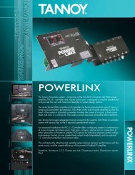
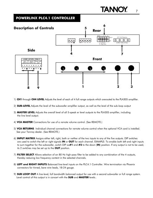
POWERLINX PLC4.1 CONTROLLER<br />
{<br />
7<br />
Description of Controls<br />
5<br />
Rear<br />
6<br />
SUB 1 2 3 4<br />
L R L R L R L R L R<br />
OUT<br />
UP = Full Frequency<br />
+10V MR<br />
SUB 1 2 3 4<br />
1 2 3 4 5 6 7 8 910 IN<br />
L = Left Input<br />
R = Right Input<br />
1 2 3 4<br />
DOWN = 80Hz Hi-Pass<br />
Side<br />
LINE LEVEL ONLY<br />
LEFT<br />
INPUT<br />
RIGHT<br />
INPUT<br />
SUB LOOP<br />
OUT<br />
4<br />
Front<br />
7<br />
+ + +<br />
8 9<br />
1<br />
2<br />
3<br />
1) CH1 through CH4 LEVEL Adjusts the level of each of 4 full range outputs which arerouted to the PLA305 amplifier.<br />
2) SUB-LEVEL Adjusts the level of the subwoofer amplifier output, as well as the level of the sub-loop output<br />
3) MASTER LEVEL Adjusts the overall level of all 5-speak er level outputs to the PLA305 amplifier, including<br />
the line level output.<br />
4) VCA MASTER Connections for use of a remote volume control. (See REMOTE.)<br />
5) VCA RETURNS Individual <strong>channel</strong> connections for remote volume control when the optional VCA card is installed.<br />
See your <strong>Tannoy</strong> dealer. (See REMOTE.)<br />
6) INPUT MATRIX Assigns either left, right, both or neither of the two inputs to any of the five outputs. DIP switches<br />
are used to switch the left or right signals IN or OUT for each <strong>channel</strong>. EXAMPLE: To enable both left and right inputs<br />
to sum together for the subwoofer, switch DIP sw#1 and #2 to the down (IN) position. If any output is not to be used,<br />
its 2 switches may be set up to the OUT position.<br />
7) FILTER SELECT Allows selection of an 80 Hz high-pass filter to be added to any combination of the 4 outputs,<br />
thereby reducing low frequency content in the selected <strong>channel</strong>s.<br />
8) LEFT and RIGHT INPUTS Balanced line-level inputs on the PLC4.1 Controller. Wire termination via Phoenix<br />
connectors for tinned, bare wire leads, 18-24 gauge.<br />
9) SUB LOOP OUT A line-level, full bandwidth balanced output for use with a second subwoofer or full range system.<br />
Level control of this output is in concert with the SUB and MASTER levels..