REFERENCE MONITORS SYSTEM 1000 USER MANUAL - Tannoy
REFERENCE MONITORS SYSTEM 1000 USER MANUAL - Tannoy
REFERENCE MONITORS SYSTEM 1000 USER MANUAL - Tannoy

Create successful ePaper yourself
Turn your PDF publications into a flip-book with our unique Google optimized e-Paper software.
<strong>REFERENCE</strong> <strong>MONITORS</strong><br />
<strong>SYSTEM</strong> <strong>1000</strong><br />
<strong>USER</strong> <strong>MANUAL</strong>
INTRODUCTION<br />
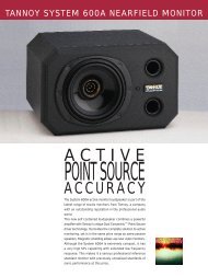
Thank you for purchasing <strong>Tannoy</strong> System <strong>1000</strong> Monitors.<br />
This loudspeaker is a compact, professional near/mid-field reference monitor. Using<br />
an advanced 10” Dual Concentric driver, if offers the advantages of point source<br />
operation in a very cost-effective design. The attractive octagonal shape of the<br />
cabinet with its rounded edge corners and front panel contributes to the excellent<br />
acoustic performance of the cabinet.<br />
Due to its point source operation it will perform equally well in both landscape and<br />
portait orientations, whether it is used in the near-field on top of the mixing console,<br />
or for mid-field monitoring.<br />
This manual is intended to provide the user with some useful advice on how to install<br />
and use the loudspeakers, as well as more technical information about how the<br />
system is designed, and its detailed specifications. We hope this will help you to get<br />
the best results from your monitoring system.<br />
OPERATING INSTRUCTIONS<br />
Unpacking and visual checks<br />
To get the speaker out of the carton without damage open the end flaps fully and<br />
bend them right back. Turn the package upside-down on the floor and lift the carton<br />
vertically up to leave the speaker resting on its packing tray.<br />
Inspect each speaker for signs of transit damage. In the unlikely event of this having<br />
occurred inform the carrier and the supplier. Keep all the packaging if damage has<br />
occurred as this will show evidence of excessive handling forces. It is also a good<br />
idea to keep the carton for future transportation.<br />
Preliminary recommendation<br />
Initially we would like to give some words of warning on the high sound levels which<br />
these speakers are capable of generating over sustained periods of time. Levels over<br />
95 dB for 8 hours per day will eventually cause permanent hearing loss. Because<br />
<strong>Tannoy</strong> Monitors have very low levels of time, amplitude and frequency distortion it<br />
is not always obvious that the sound level is high while working with them.<br />
For continuous exposure we recommend the occasional use of a sound level meter<br />
capable of integrating the sound level over a period of exposure according to noise<br />
control standards. This should be used to check that noise levels are always within<br />
safety limits.<br />
Location and support for the loudspeakers.<br />
When choosing a suitable location for the monitors, bear in mind that the physical<br />
mounting of loudspeakers can have a large influence on performance. For best<br />
results the monitors should be mounted on a rigid structure, supported on pads<br />
making contact with the laminated panel. Self-adhesive foam pads are provided with<br />
the loudspeakers for that purpose. If you intend to arrange the monitors in landscape<br />
format, detach the whole pad from the backing paper and stick it on the large side to<br />
become the bottom of the cabinet ; for portrait arrangement the pad is pre-cut so that<br />
one half can be easily detached to match the smaller size of the bottom panel.
We recommend location of the monitors so that the drive units are toed inwards, with<br />
their axes oriented towards the listening position. The distance between the two<br />
speakers should be 1.5 to 2.5 metres, depending on the monitoring position. The<br />
distance between the monitoring position and each speaker should be slightly greater<br />
than the distance between the speakers. If the speakers are placed too close to each<br />
other the full stereo image may not develop, on the other hand if you place them too<br />
far apart you will notice a hole in the middle of the stereo image.<br />
Ensure that the console position does not obscure the direct sound radiation from the<br />
Dual Concentric drive unit when sitting down. The engineer and producer should<br />
have a clear, uninterrupted view of the monitor loudspeakers.<br />
Connecting the loudspeakers.<br />
The loudspeaker can be connected to the amplifier via to two different modes of<br />
operation : conventional wiring and bi-wiring. In the latter mode two separate pairs of<br />
cables are used to connect the amplifier to the monitor, i.e. one for the low-frequency<br />
(LF) and one for the high-frequency (HF) sections.<br />
The termination panels located at the back of the loudspeakers must be set<br />
according to the desired wiring mode, as shown on the figures below. The<br />
termination panels are factory set for normal wiring operation, as shown on Fig.1. In<br />
this mode the LF and HF banana sockets are connected together by two gold-plated<br />
links, allowing a single twin core cable to drive the loudspeaker. For bi-wiring<br />
operation, loosen the banana sockets (turn knob anti-clockwise) and remove the two<br />
gold-plated links ; then connect each twin core cable to one pair of red / black<br />
terminals of the speaker (one is marked LF and the other HF), as shown on Fig. 2. At<br />
the other end (amplifier) the two cables are connected together, positive to positive,<br />
negative to negative.<br />
Figure 1. Normal wiring<br />
Figure 2. Bi-wiring<br />
When connecting the speakers it is essential that consistent polarity is observed. The<br />
red terminal(s) on the loudspeaker must be connected to the red or positive<br />
terminal(s) on the power amplifier, and the black terminal(s) on the loudspeaker must<br />
be connected to the black, negative or ground terminal(s) of the power amplifier.<br />
When operating the loudspeakers in normal wiring mode, it is important that the two<br />
gold-plated links are properly tightened to ensure a perfect electrical connection<br />
between LF and HF terminals.<br />
The types of cable used to connect the speakers to the power amplifier will<br />
marginally affect the sound. The cross-sectional area of the cable should be large<br />
enough so as not to affect the damping factor, and generally a cable with a crosssectional<br />
area of 2.5 mm² or greater is recommended.
Before connecting the amplifier and the monitors, it is advisable to ensure that there<br />
is no signal present either by turning amplifiers gain down or by lowering the output<br />
faders.<br />
Power amplifiers.<br />
The power amplifier should be reasonably well matched in power to the rating of the<br />
speakers. A recommended range of power can be found in the specifications (at the<br />
end of this manual). The use of a powerful amplifier (i.e. the higher figure of the<br />
specified power range) provides headroom which is useful especially for highly<br />
dynamic programme materials.<br />
Because of the high peak power handling of the <strong>Tannoy</strong> monitors, responsible use of<br />
even more powerful amplifiers should not represent a danger for the speakers if the<br />
amplifiers are not overdriven.<br />
<strong>SYSTEM</strong> DESCRIPTION AND PHILOSOPHY<br />
Drive unit.<br />
A loudspeaker design naturally divides into various parts: cabinet, drive unit(s) and<br />
crossover. The design of these parts cannot take place in isolation as they are all<br />
interdependent.<br />
The drive unit used in the System <strong>1000</strong> monitors is part of the latest generation of<br />
Dual Concentric units designed by <strong>Tannoy</strong>. Among many others features, this range<br />
of drivers incorporate a dual magnet assembly, ‘tulip’ HF waveguide and injection<br />
moulded polypropylene LF cone.<br />
The design of the HF waveguide has been arrived at by making extensive use of<br />
CAD (computer aided design). It matches the acoustic source impedance at the HF<br />
diaphragm into the acoustic environment, shaping the wavefront as it travels down<br />
from the diaphragm ensuring equal path lengths to achieve a spherical wavefront.<br />
Wavefront shaping begins at the diaphragm surface and, because the compression<br />
ratio can be kept relatively low with this design, the distortions due to air nonlinearities<br />
are minimised. A hyperbolic flare has been chosen for optimum low<br />
frequency performance at the crossover point.<br />
The HF diaphragm is made from aluminium and magnesium alloy, with optimised<br />
shape and thickness providing rigid piston behaviour up to 25 kHz. The diaphragm<br />
assembly is suspended by a precision moulded, inert nitrile rubber surround. Its very<br />
narrow roll eliminates resonances below 25 kHz and provides a very stable and<br />
consistent mounting. The roll form ensures high excursions can take place if<br />
necessary yet provides a fatigue-indestructible assembly.<br />
The HF voice coil assembly incorporates a high temperature copper wire chemically<br />
bonded onto a kapton former fitting onto the outside of the HF diaphragm skirt. The<br />
thermal power handling of the voice coil is greatly increased thanks to its ferrofluid<br />
filled magnetic gap.<br />
Physically, the whole HF assembly self centre mounts onto the back of the low<br />
frequency assembly using three screws carrying with it the self-centring HF<br />
diaphragm. Production and field service is therefore virtually foolproof and extremely<br />
consistent.<br />
The LF unit uses a CNC precision injection moulded polypropylene cone, terminated<br />
by a nitrile rubber, high-compliance surround. The characteristic cone termination<br />
impedance is matched by the surround material independently of the required<br />
suspension compliance. The unit system compliance is provided by the rear<br />
suspension where the best degree of mechanical control can be provided.
The shape of the LF cone has been calculated to match the HF hyperbolic<br />
waveguide ensuring the wavefront remains spherical and perpendicular to the cone<br />
surface throughout the propagation.<br />
Purpose-designed trim rings are used to blend the HF wavefront into the cabinet.<br />
This feature has been shown in our research to be the biggest single factor in<br />
providing smooth HF radiation in Dual Concentrics.<br />
The heart of the LF unit is the motor system comprising the magnet and voice coil.<br />
The choice of magnet operating point parameters, air gap flux strength, voice coil<br />
details (number of turns, resistance, winding length, diameter etc.), moving mass,<br />
dynamic compliance and drive unit radiating area presents a very complex<br />
mathematical problem where the solutions can take many different forms. Reaching<br />
the correct answers is much easier if computers can be called on to assist with<br />
solving the equations, as <strong>Tannoy</strong> do for its drivers.<br />
Cabinet.<br />
Aside the drive units, cabinet design plays a major role in the acoustic performance<br />
of a speaker system. Among the problems which can contribute to the degradation of<br />
the emitted sound field, diffractions and reflections caused by the cabinet boundaries<br />
are too often overlooked although they are the cause of most of the irregularities<br />
heard and measured in the higher frequency areas.<br />
In that respect conventional rectangular, sharp corner boxes perform especially<br />
poorly. On the other hand, the shape of the System <strong>1000</strong> has been designed with<br />
careful attention paid regarding the sculptured front panel to provide smooth,<br />
rounded edges which minimise side diffractions.<br />
Another problem involved in cabinet design is to ensure that the box will effectively<br />
behave as neutrally as possible, ideally without interfering at all with the sound field<br />
emitted by the drive unit and the port. There are two main ways the box can get into<br />
vibration. First there can be a mechanical transfer of energy between the drive unit<br />
and the cabinet front panel. Preventing this requires the use of a rigid and stiff front<br />
baffle, which is achieved on the System <strong>1000</strong> by a very thick and compact MDF<br />
panel. The second way the cabinet can get into vibration is by transmission from<br />
acoustical to mechanical energy. Since high acoustic pressures are present inside<br />
the cabinet this is quite likely to occur if no attention is paid in order to minimise it.<br />
Here the use of rigid panels is also helpful but, since their stiffness cannot be infinite<br />
and therefore their resonance’s only shifted towards higher frequencies, enough<br />
damping has to be provided in the cabinet assembly, including panels and joints.<br />
Due to its octagonal shape and its cabinet construction, the System <strong>1000</strong> perform<br />
very well in that respect. Its shape tends to decrease the largest dimensions of each<br />
side panel, which reduce low frequency resonance’s, while the doubled number of<br />
side provides additional damping.<br />
In addition to the cabinet construction the volume and port tuning have been<br />
carefully calculated to give the best set of parameters for monitoring loudspeakers.<br />
There is a fundamental relationship in loudspeakers between efficiency, cabinet<br />
volume and low frequency performance given that minimal amplitude variations can<br />
be tolerated (as in monitoring situations). The set of parameters that are arrived at<br />
as a solution are inevitably a compromise and the skill of <strong>Tannoy</strong> has always been<br />
shown to be getting these particular parameters correct for the application.<br />
The Sum of the parts.<br />
The crossover is an important, sometimes difficult part of the design. However the<br />
use of an optimised, well designed drive unit makes the task easier and allows using<br />
simpler networks, which generally give better results.<br />
It is also important to point out that a very important benefit of the Dual Concentric<br />
technology is in connection with the crossover. With conventional discrete multidrivers<br />
speakers, the crossover has a dramatic effect on the speaker performance in
the frequency range where the different drivers overlap, especially on off-axis<br />
response and on spatial dispersion. Actually, because of the detrimental effects<br />
resulting from the fact that they are non-coincident, the drivers should ideally work in<br />
completely split ranges of frequency. High order low and hi-pass filters are therefore<br />
required to reduce the overlap range. Apart from the fact that it makes the design<br />
more complex, requires more accurate components and increases the costs, a major<br />
drawback is that higher order filters involve increased phase and group delay<br />
distortion, which can be quite perceptible. On the other hand the low order filter used<br />
with Dual Concentric drivers achieve a smooth phase response.<br />
The integration of all the features described above is what makes the whole<br />
loudspeaker system even greater than the sum of the individual parts.<br />
SERVICING<br />
Cabinet finish.<br />
To remove marks and scuffs use a medium soft brush. If necessary, a little warm<br />
water and detergent can be used but under no circumstances use a solvent or<br />
abrasive cleaner. The surface will change colour when wet but will return to normal<br />
when dry. For touch-up of paint chips contact your local <strong>Tannoy</strong> service agent for<br />
materials and guidance.<br />
Dual Concentric driver removal.<br />
Lay the cabinet on its back. Remove the four hexagonal bolts and set aside. Ease<br />
the driver from the front of the cabinet taking care not to mark the front surface.<br />
Use a piece of stout cardboard to lever against if necessary. Remove the driver, note<br />
the polarity of the internal connections and disconnect the internal wiring. Take care<br />
not to damage the moving parts of the LF driver.<br />
To refit the driver, connect the cables from the crossover to the LF and HF terminals.<br />
Fit the driver into mounting hole, making sure that the internal connecting cables are<br />
not trapped between the HF unit and the cabinet crossbrace. Fasten the bolts finger<br />
tight and then progressively torque them down.<br />
Drive unit servicing.<br />
The HF unit may be fitted with a new diaphragm assembly or replaced as a complete<br />
assembly for speed. In either case, with the driver face down, release the three bolts<br />
securing the HF assembly and lift the HF unit vertically upwards and away from<br />
magnetic attraction caused by the LF magnet. Replace the diaphragm - it is selfcentring<br />
- or the complete unit, taking care to align the parts correctly.<br />
To refit the HF unit, hold it about 300 mm vertically above the LF magnet in both<br />
hands while resting on your elbows. Slide your elbows apart and lower the HF unit<br />
onto the back of the LF magnet. As the HF unit gets close to the magnet you will feel<br />
the magnetic fields repelling. Align the fixing holes and secure with the bolts,<br />
tightening down evenly. Do not tighten the bolts finally until you are sure the HF unit<br />
is seated correctly and the two magnet systems appear parallel.<br />
The LF unit may be re-coned in the normal way. Ease the trim ring from the rubber<br />
surround and remember to refit it. The trim ring forms an integral part of the HF<br />
dispersion system. Use only the parts and adhesive supplied in the re-cone kit.
Crossover.<br />
The crossover is mounted on the internal vertical brace, behind the terminal panel.<br />
To inspect it, first remove the panel by releasing the hexagonal screws. Take care to<br />
avoid undue stress on the cables and components.<br />
To remove the crossover completely the cables must be disconnected from the drive<br />
unit. Please proceed as above to remove the drive unit.<br />
Checking the unit.<br />
The speaker can be checked using a sine wave generator. A high quality, low<br />
distortion (preferably a beat frequency) oscillator will be required to check for any<br />
buzz and rattle noise generated by the drive unit. The voltage to be applied at the<br />
speaker terminals should be about 3V rms (the speakers should be free from buzz<br />
and rattle at any audio frequency).<br />
Checking the speaker at higher levels is permissible, provided that the lower<br />
frequency of the sweep is limited according to the voltage level ; for instance with<br />
levels exceeding 10V rms the frequency should be kept above 100 Hz.<br />
List of spare parts.<br />
PART NUMBER
DO NOT SHIP ANY PRODUCT TO TANNOY WITHOUT PREVIOUS<br />
AUTHORISATION.<br />
This warranty in no way affects your statutory rights.<br />
CURVES<br />
Figure 1. On axis anechoic response.
Figure 2. Impedance.<br />
TECHNICAL SPECIFICATIONS<br />
System<br />
Frequency response (1)<br />
Recommended amplifier power<br />
45 Hz - 20 kHz<br />
60 to 200 W rms into 8 Ω<br />
Power handling Average (2) Programme<br />
100 W rms 200 W rms<br />
Nominal Impedance<br />
Sensitivity (3)<br />
8 Ω<br />
94 dB SPL / 1 W @ 1 m<br />
Distortion < 0.5 %<br />
Dispersion (@ -6dB)<br />
Crossover frequency<br />
90° conical<br />
1500 Hz
Cabinet<br />
Drive unit 10’’ <strong>Tannoy</strong> Dual Concentric type 2513<br />
Low frequency design<br />
Cabinet construction<br />
Cabinet finish<br />
Cabinet dimensions (HxWxD)<br />
Cabinet weight<br />
Shipping dimensions (HxWxD)<br />
Shipping weight<br />
Optimised bass-reflex load, in 32 litres<br />
MDF (36 mm front panel)<br />
Spray ‘F’ Vinyl<br />
541 mm x 331 mm x 298 mm<br />
16.5 kg<br />
660 mm x 415 mm x 370 mm<br />
19 kg<br />
NOTES : (1) +/- 3 dB , measured at 1m in an anechoic chamber.<br />
(2) Long term power handling capacity as defined in EIA standard RS426A.<br />
(3) Averaged over specified bandwith for half-space environment. For anechoic conditions the figure is to be<br />
decreased by 3 dB.<br />
<strong>Tannoy</strong> operate a policy of continuous research and development. The introduction of new materials or manufacturing<br />
methods will always equal or exceed the published specifications which <strong>Tannoy</strong> reserve the right to alter without prior<br />
notice. Please verify the latest specifications when dealing with critical applications.
Declaration of Conformity<br />
The following apparatus is/are manufactured in the United Kingdom by <strong>Tannoy</strong> Ltd<br />
of Rosehall Industrial estate, Coatbridge, Scotland, ML5 4TF and conform(s) to the<br />
protection requirements of the European Electromagnetic Compatibility Standards<br />
and Directives relevant to Domestic Electrical Equipment. The apparatus is<br />
designed and constructed such that electromagnetic disturbances generated do not<br />
exceed levels allowing radio and telecommunications equipment and other<br />
apparatus to operate as intended, and, the apparatus has an adequate level of<br />
intrinsic immunity to electromagnetic disturbance to enable operation as specified<br />
and intended.<br />
Details of the Apparatus:<br />
Associated Technical File:<br />
Applicable Standards:<br />
<strong>Tannoy</strong> Monitor Loudspeaker<br />
Model Number: System <strong>1000</strong><br />
EMCSYS<strong>1000</strong><br />
EN 50081-1 Emission<br />
EN 50082-1 Immunity<br />
Signed:<br />
Position:<br />
Technical Manager<br />
<strong>Tannoy</strong> Professional<br />
Date: 16 th July 1998
For <strong>Tannoy</strong> Ltd
<strong>Tannoy</strong> Loudspeakers are manufactured<br />
in Great Britain by :<br />
<strong>Tannoy</strong> Ltd, Rosehall Industrial Estate, Coatbridge,<br />
Strathclyde, ML5 4TF, SCOTLAND<br />
Telephone: +44 (0)1236 420199 Fax: +44 (0)1236 428230<br />
Internet:http://www.tannoy.com<br />
TGI/<strong>Tannoy</strong>, 300 Gage Avenue, Kitchener, Ontario, CANADA, N2M 2C8<br />
Telephone: (519) 745 1158 Fax: (519) 745 2364<br />
<strong>Tannoy</strong> Nederland BV, Anthonetta Kuijlstraat 19, 3066 GS, Rotterdam THE NETHERLANDS<br />
Telephone: (010) 2860554 Fax: (010) 2860431<br />
<strong>Tannoy</strong> is a member of the Group of Companies Issue 2 Part No. 6481 0281