You also want an ePaper? Increase the reach of your titles
YUMPU automatically turns print PDFs into web optimized ePapers that Google loves.
CONTENTS<br />
1.0: IMPORTANT SAFETY INSTRUCTIONS 1.1 Introduction<br />
2.0: THE BASICS 2.1 Unpacking and visual checks<br />
2.2 Preliminary recommendation<br />
3.0: REVEAL D SERIES FEATURES 3.1 Analog Input<br />
3.2 Digital SPDIF Input<br />
3.3 Connecting your speakers<br />
3.4 User Controls<br />
4.0: EQUALISATION POSSIBILITIES<br />
5.0: GUIDE TO SETTING THE EQUALISATION<br />
6.0: PLACEMENT OF THE SPEAKERS 6.1 Orientation (R6D & R8D)<br />
6.2 Positioning (R6D & R8D)<br />
6.3 Positioning (R66D)<br />
6.4 Speaker Mounting<br />
6.5 Bass Ports<br />
7.0: PERFORMANCE DATA Reveal 6D<br />
Reveal 8D<br />
Reveal 66D<br />
8.0: TECHNICAL SPECIFICATIONS<br />
9.0: DIMENSIONS<br />
10.0: SERVICING 6.1 Cabinet Finish<br />
6.2 Driver Removal<br />
6.3 Amplifier Removal<br />
6.4 Spare parts<br />
11.0: WARRANTY<br />
12.0: DECLARATION OF CONFORMITY<br />
1.0: IMPORTANT SAFETY INSTRUCTIONS<br />
1. Read these instructions.<br />
2. Keep these instructions.<br />
3. Heed all warnings.<br />
4. Follow all instructions.<br />
5. Do not use this apparatus near water.<br />
6. Clean only with dry cloth.<br />
The lightning flash with an arrowhead symbol within an<br />
equilateral triangle, is intended to alert the user to the<br />
presence of uninsulated “dangerous voltage” within the<br />
product’s enclosure that may be of sufficient magnitude<br />
to constitute a risk of electric shock to persons.<br />
7. Do not block any ventilation openings. Install in accordance with manufacturer’s instructions.<br />
8. Do not install near any heat sources such as radiators, heat registers, stoves, or other apparatus (including amplifiers) that<br />
produce heat and ensure adequate air circulation around the rear of the product.<br />
9. Do not defeat the safety purpose of the polarised or grounding-type plug. A polarised plug has two blades with one wider<br />
than the other. A grounding type plug has two blades and a third grounding prong. The wide blade or the third prong are<br />
provided for your safety. If the provided plug does not fit into your outlet, consult an electrician for replacement of the<br />
obsolete outlet.<br />
10. Protect the power cord from being walked on or pinched particularly at plugs, wall sockets, and the point where they exit<br />
from the apparatus.<br />
11. Only use attachments/accessories specified by the manufacturer.<br />
12. Unplug this apparatus during lightning storms or when unused for long periods of time.<br />
13. Refer all servicing to qualified service personnel. Servicing is required when the apparatus has been damaged in any way,<br />
such as power-supply cord or plug is damaged, liquid has been spilled or objects have fallen into the apparatus, the<br />
apparatus has been exposed to rain or moisture, does not operate normally, or has been dropped.<br />
14. WARNING: To reduce the risk of fire or electrical shock, this apparatus should not be exposed to rain or moisture and objects<br />
filled with liquids, such as vases, should not be placed on this apparatus.<br />
15. To completely disconnect this equipment from the mains, disconnect the power supply cord plug from the wall socket.<br />
16. The mains plug on the power supply cord shall remain readily accessible.<br />
17. SAFETY WARNING: This product design uses amplifier output stages with substantial standing currents for optimal sound<br />
quality. Fit and use the protective heat shield when adjusting the feature controls above the heatsink, to prevent contact<br />
with uncomfortably hot surfaces when monitoring at continuously high sound pressure levels. Use the small tool provided<br />
to adjust the switches in accordance with the instructions in the user manual.<br />
ELECTRICAL REQUIREMENTS<br />
Check that the voltage rating displayed on the rear panel is correct for your area before connecting. If it is incorrect, please<br />
refer to your local dealer or authorised service agent, as no user adjustment is provided.<br />
Warning!<br />
• To reduce the risk of fire or electric shock, do not expose this apparatus to rain or moisture.<br />
• Be advised that different operating voltages require the use of different types of line cord and attachment plugs.<br />
• Check the voltage in your area and use the correct type. See table below:<br />
Voltage Line plug according to standard<br />
110-125V UL817 and CSA C22.2 no 42.<br />
220-230V CEE 7 page VII, SR section 107-2-D1/IEC 83 page C4.<br />
240V BS 1363 of 1984. Specification for 13A fused plugs and switched and un-switched socket outlets.<br />
Service<br />
There are no user-serviceable parts inside. Qualified personnel must perform all service. Servicing is required when: -<br />
• The unit has been damaged in any way, such as when the power-supply cord or plug is damaged.<br />
• The unit has been exposed to rain or moisture, or liquid has been spilled into the unit.<br />
• Objects have fallen into the unit.<br />
• The unit does not work properly.<br />
• The unit has been dropped.<br />
EUROPEAN MODELS<br />
A mains cable is supplied with an IEC moulded socket at one end and a moulded mains plug at the other end. Where the<br />
moulded plug is fitted with a mains fuse, always replace with the same 5A rated fuse. If the fitted plug is unsuitable for your<br />
type of outlet sockets, it should be cut off and disposed of safely, in case it is inserted into a live socket elsewhere. The wires in<br />
the mains cable are coloured in accordance with the following code:<br />
GREEN AND YELLOW EARTH BLUE NEUTRAL BROWN LIVE<br />
The exclamation point within an equilateral triangle is<br />
intended to alert the user to the presence of important<br />
operating and maintenance (servicing) instructions in the<br />
literature accompanying the product.<br />
2 3
AS THE COLOURS OF THE WIRES IN THE MAINS CABLE MAY NOT CORRESPOND WITH THE COLOURED MARKINGS<br />
IDENTIFYING THE TERMINALS IN YOUR PLUG, PROCEED AS FOLLOWS:<br />
The wire which is coloured GREEN AND YELLOW must be connected to the terminal in the plug which is marked either by the<br />
letter E, the earth safety symbol, or coloured GREEN or GREEN and YELLOW.<br />
The wire which is coloured BLUE must be connected to the terminal in the plug which is marked by the letter N or coloured BLACK<br />
The wire which is coloured BROWN must be connected to the terminal in the plug which is marked by the letter L or coloured RED.<br />
Ensure that the terminals are tightened securely, and no loose strands of wire are present. Ensure cord grip is clamped over<br />
outer sheath of cable, rather than over the wires.<br />
FUSE PROTECTION<br />
An additional mains fuse is provided in the IEC power inlet on the back of the loudspeaker, which can only be removed with<br />
the power cord unplugged. This must be replaced by a fuse of the same type and ratings (see Specifications or refer to rear<br />
panel).<br />
INSTALLATION<br />
Do not install this equipment in an enclosed space. Do not limit free ventilation and movement of air around the back panel.<br />
Do not install this equipment in a cupboard with a closed door. Allow for a distance of 150mm (6 inches) of free air space<br />
around all sides, top, bottom and the back panel of this product. The user must be able to see the blue coloured front panel<br />
of this product when in use.<br />
EMC<br />
This equipment has been tested and found to comply with the limits for a Class B digital device, pursuant to part 15 of the FCC<br />
Rules. These limits are designed to provide reasonable protection against harmful interference in a residential installation. This<br />
equipment generates uses and can radiate radio frequency energy and, if not installed and used in accordance with the<br />
instructions, may cause harmful interference to radio communications. However, there is no guarantee that interference will not<br />
occur in a particular installation. If this equipment does cause harmful interference to radio or television reception, which can<br />
be determined by turning the equipment off and on, the user is encouraged to try to correct the interference by one or more of<br />
the following measures:<br />
Reorient or relocate the receiving antenna.<br />
Increase the separation between the equipment and receiver.<br />
Connect the equipment into an outlet on a circuit different from that to which the receiver is connected.<br />
Reorient or coil cables.<br />
If necessary, consult the dealer or an experienced radio/television technician for additional suggestions.<br />
Any cables the user adds to the device must be shielded to be in compliance with the FCC standards. Any unauthorised modification<br />
to this device could result in the revocation of the end user’s authority to operate this device.<br />
This device complies with Part 15 of FCC rules. Operation is subject to the following two conditions: (1) This device may not<br />
cause harmful interference, and (2) This device must accept any interference received, including interference that may cause<br />
undesired operation.<br />
Canada<br />
Industry Canada Class B emission compliance statement. This Class B digital apparatus complies with Canadian ICES-003.<br />
Avis de conformite a la reglementation d'Industrie Canada. Cet appareil numerique de classe B est conforme a la norme N<strong>MB</strong>-<br />
003 du Canada.<br />
1.1: INTRODUCTION<br />
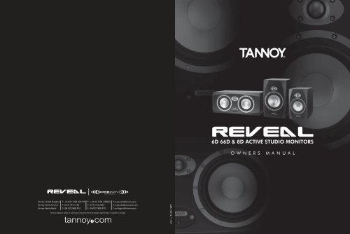
The <strong>Tannoy</strong> Reveal Digital range of near field monitoring speakers builds upon the success and worldwide reputation of the<br />
famous original <strong>Tannoy</strong> Reveal Active. Since the launch of the original <strong>Tannoy</strong> Reveal Active in 1998 there have been significant<br />
advances in digital speaker measuring techniques, acoustic CAD design and simulation, and precision manufacturing processes.<br />
The <strong>Tannoy</strong> Reveal Digital range now provides greater bandwidth, significantly lower levels of distortion, smoother responses,<br />
more accurate phase control, and higher sensitivity levels; all within compact cabinet sizes. Also, much has been learnt about<br />
the near field listening environment - the effects of boundary walls, acoustic reflections from mixing console surfaces and the<br />
acoustic properties of often sparsely prepared PC/Mac post production editing situations.<br />
The <strong>Tannoy</strong> Reveal Digital range of monitoring speakers can be optimised for far field, mid field and near/close field free space<br />
situations right through to far field, mid field and near/close field situations in difficult acoustic spaces such as meter bridge<br />
positions, adjacent to walls or reflecting surfaces and space restricted PC/Mac based sound editing environments.<br />
Acoustic space environments are referred to as 4pi, 2pi and pi representing the solid angle in space (steradians) into which the<br />
speaker is radiating. These environments are frequently referred to as free space, half space and quarter space listening<br />
conditions . The type of acoustic space into which a speaker radiates, defined by nearby solid boundaries, affects the acoustic<br />
air load presented to the speaker and so the relative radiating efficiency at various frequencies. In different pi spaces the linearity<br />
of the amplitude response changes, especially within the band 50Hz to 800Hz.<br />
Varying distances encountered between the monitors and the listener are generally referred to as far field (greater than 3m or<br />
10 feet), mid field (2 to 3m or 6 to 10 feet), near field (1 to 2m or 3 to 6 feet) and close field (around 0.5m or 1.5 feet). The<br />
proximity of the listener to the speaker changes the way the listener perceives the sound balance from the speaker. At large<br />
distances from an acoustic source plane waves are perceived. At small distances from an acoustic source the waves appear<br />
spherical.<br />
2.0: THE BASICS 2.1: UNPACKING AND VISUAL CHECKS<br />
The Reveal 6D’s are packed in pairs and the Reveal 8D and 66D’s are packed singly. To remove the speakers from the carton<br />
without damage open the end flaps fully and bend them right back (remember they are packed in pairs). Turn the package<br />
upside-down on the floor and lift the carton vertically up to leave the speakers resting on their packing tray. Nothing on or in<br />
your speakers should rattle about. Inspect each speaker for signs of transit damage. In the unlikely event of this having occurred<br />
inform the carrier and the supplier. Keep all the packaging if damage has occurred, as this will show evidence of excessive<br />
handling forces. It is also a good idea to keep the packaging if possible for future transportation.<br />
2.2: PRELIMINARY RECOMMENDATION<br />
Initially we would like to give a word of warning on high sound levels, which these speakers are capable of generating over<br />
sustained periods of time. Levels over 95 dB for 8 hours per day can eventually cause permanent hearing loss. Because <strong>Tannoy</strong><br />
monitors have very low levels of time, amplitude and frequency distortion it is not always obvious that the sound level is high<br />
while working with them.<br />
For continuous exposure we recommend the occasional use of a sound level meter capable of integrating the sound level over<br />
a period of exposure according to noise control standards. This should be used just to check that noise levels are always within<br />
safety limits.<br />
3.0: REVEAL D SERIES FEATURES<br />
A set of DIP switches on the rear panel of each speaker can be set to choose the optimum speaker response for these real life<br />
and often difficult situations, so that the frequency response from the speaker is always substantially flat. We are not equalising<br />
the room modes due to standing waves or resonant structures, we are equalising the speaker to take account of the varying air<br />
load presented by the room and surrounding large structures such as the mixing desk.<br />
The switches are arranged in groups according to their function and each switch can be set to the 'on' (down) or 'off' (up) position<br />
in various combinations to achieve a flatter, more balanced response within a wide variety of acoustic spaces and with far, mid,<br />
near and close field monitoring positions.<br />
Figure 1 shows the range of equalisation available in the 50Hz to 800Hz region and also shows the degree of trim available<br />
in the bass, upper midrange and high frequency areas,<br />
4 5
An A/V 80Hz high pass filter switch provides instant conversion to 5.1 and higher order systems where a separate subwoofer<br />
below 80Hz is required. Filter characteristics are according to the international standards for this setup. This response is also<br />
shown diagramatically in Figure 1.<br />
Listening to well recorded male or female spoken word or vocals at the normal listening position is a good way to check and<br />
optimise the available settings. Difficult environments and variable listening distances produce varying degrees of boost from<br />
the flat position in the 50Hz to 800Hz area. Graphical representations of the responses available by setting the switches are<br />
shown below. The linear or flat response positions for the DIP switches are always clearly shown in the diagrams below and<br />
also on the rear panel of the speaker.<br />
The <strong>Tannoy</strong> ActivAssist software package is available to help with the DIP switch settings. Using a standard laptop with the<br />
microphone and cables supplied in the pack, the performance of the speaker in a particular environment can be assessed and<br />
a recommended set of switches set up.<br />
3.4: USER CONTROLS<br />
A/V (80Hz): a switch to the bottom left of the bank of DIP switches sets the system high pass filter to either flat or –6dB at 80Hz.<br />
The 80Hz setting is used when the speakers are in combination with a subwoofer for low frequency effects such as Dolby Digital,<br />
AC3, DTS etc playback situations. For all other situations set this switch to flat. This response can be seen in Figure 1 above.<br />
Left/Right/Mono: a switch at the bottom left of the bank of DIP switches sets the SPDIF DAC to sense the left, right or combined<br />
stereo information (mono) from the digital stream. Set the left hand speaker to ‘Left’ and the right hand speaker to ‘Right’ for<br />
2 channel stereo, or to ‘mono’ for single speaker monitoring.<br />
Analogue/Digital: a switch adjacent to the XLR/Jack combi socket selects whether the speaker is receiving a signal from the<br />
balanced/unbalanced analogue input combi socket, or, from the SPDIF phono (RCA) digital input. Both may be connected<br />
simultaneously but only one can be selected at any one time.<br />
4.0: EQUALISATION POSSIBILITIES<br />
+3dB<br />
+1.5dB Large Medium Normal +1.5dB +2dB<br />
+0.75dB<br />
+1dB<br />
0dB Flat Flat Flat Flat<br />
-2dB -0.75dB -1dB<br />
-1dB<br />
-4dB<br />
-1.5dB<br />
-2dB<br />
-2dB<br />
-6dB<br />
-3dB<br />
-8dB<br />
-3dB<br />
( AV 80Hz HiPass on slide switch)<br />
Fig. 1. Full range of equalisation and trim available.<br />
3.1: ANALOG INPUT<br />
XLR:<br />
2= +ve (hot), 3= -ve (cold), 1= screen, shield or signal ground.<br />
3 way Jack: tip=+ve (hot), ring= -ve (cold), sleeve= screen, shield or signal ground.<br />
For unbalanced XLR connection short pin 1 to pin 3 and use 2= +ve (hot), 3= -ve (ground).<br />
For unbalanced 3 way Jack short ring to sleeve and use tip= +ve (hot), sleeve= -ve (ground).<br />
Note: In the diagrams which follow, the corner frequency shown as 50Hz will vary according to the specification relating to<br />
the particular model which has been chosen. Please refer to the detailed specification section at the end of this manual for more<br />
details. Smaller models will have a slightly higher corner frequency and larger models will have a lower corner frequency. The<br />
diagrams have been prepared to make the visualisation of the EQ possibilities easier to understand. The transitions of the<br />
speaker amplitude response bewteen frequency bands will be gradual and not as sharp as the diagrams show. Note the +10dB<br />
and -10dB calibrations on the charts. EQ settings should never be at opposite extremes eg -8dB low mid contour with -2dB<br />
mids and +3dB highs.<br />
There are 4 basic frequency bands that can be adjusted. The range of adjustment is purposely restricted so that although effective<br />
in the majority of environments, it is difficult to set the speaker to have a totally unacceptable response. A 'flat' setting means<br />
flat within specification as measured in an anechoic chamber, on axis, under free field conditions in the far field (3 metres away).<br />
The frequency bands are:<br />
Bass Corner Frequency: The 'Q' value of the bass unit and cabinet volume alignment can be altered giving +3dB, flat, -<br />
1.5, -3, and -4.5 dB relative to the -3dB point shown in the specification. This provides a degree of boost and cut in the 45Hz<br />
to 65Hz area. Figure 2 shows the range of adjustment available together with the DIP switch settings for the first 4 DIP switches.<br />
All other DIP switches are shown in the anechoic flat positions.<br />
Diagramatic View of EQ Dip Switches: LF EQ + Av Filter<br />
20 way DIP Switch Bank (4+4+2+4+6)<br />
LF EQ Low Mids Hz Up Mids<br />
Highs<br />
3.2: DIGITAL SPDIF INPUT<br />
The input impedance is the SPDIF specification at 75 ohms and the 24 bit DAC supports 44.1, 48 and 96kHz sampling rates.<br />
Please use a high quality* SPDIF coaxial phono (RCA) cable to connect the source equipment (eg CD player, DAT/ADAT or PC<br />
sound card) to one of the speakers. Connect a second (phono to phono) high quality cable from this speaker to the second<br />
speaker of the stereo pair. Select whether each speaker converts left channel or right channel audio as appropriate using the<br />
switch adjacent to the SPDIF input connector. For true mono requirements set the switch to mono. If volume can be controlled<br />
from the source equipment, set the source equipment volume level to minimum and the speaker volume control to maximum<br />
(fully clockwise). If volume cannot be controlled by the source equipment (eg a simple CD or DAT etc) set the volume control<br />
on the speaker to minimum (fully anticlockwise) to prevent excessive sound levels. The volume control adjusts the analogue<br />
level after the DA converters to preserve the full digital dynamic range.<br />
+10dB<br />
0dB re 2.8v<br />
@ 1 metre<br />
-10dB<br />
1 1 1 1 1 1 1 0 0 0 0 0 0 0 0 0 0 0 0 0<br />
1 1 1 0 1 1 1 0 0 0 0 0 0 0 0 0 0 0 0 0<br />
1 1 0 0 1 1 1 0 0 0 0 0 0 0 0 0 0 0 0 0<br />
1 0 0 0 1 1 1 0 0 0 0 0 0 0 0 0 0 0 0 0<br />
* In order to comply fully with EMC regulations, the SPDIF input and SPDIF thru should be connected using metal-shelled<br />
connectors and good quality shielded cable suitable for digital audio.<br />
0 0 0 0 1 1 1 0 0 0 0 0 0 0 0 0 0 0 0 0<br />
3.3: CONNECTING YOUR SPEAKERS<br />
80Hz AV Filter (AV on/off)<br />
Having chosen an appropriate location for your monitors and arranged them accordingly, connect the power cord to the mains<br />
socket and turn the power on. The LED on the front panel will now glow red. Push the <strong>Tannoy</strong> logo on the front panel to operate<br />
the switch to bring the amplifier out of standby mode and into operational mode. Set the volume control on the rear panel to<br />
zero (fully anticlockwise). Connect the audio signal source (console output) to the input connector (combined XLR/jack socket)<br />
or SPDIF at the back of the monitor.<br />
10Hz 20Hz<br />
50Hz 100Hz 200Hz 500Hz 1Khz 2kHz 5kHz 10kHz 20kHz<br />
Fig. 2. Range of adjustment available and settings for the first 4 DIP switches. All other DIPs set to 'Flat'<br />
6 7
Low Mid Contour Frequency: A shelving filter can be set to the flat anechoic response or set to shelve at frequencies of 800Hz,<br />
400Hz, or 200Hz in combination with the low mid contour amplitude (below) to correct half space (pi/2), quarter space (pi/4)<br />
and very difficult close field boundary conditions (pi/8 space).<br />
Diagramatic View of EQ Dip Switches: Baffle Step Filters, Low Mids, 400Hz<br />
20 way DIP Switch Bank (4+4+2+4+6)<br />
LF EQ Low Mids Hz Up Mid Highs<br />
Low Mid Contour: a shelving filter can be set to a flat anechoic response or to -2dB, -4dB, -6dB or -8dB in combination with<br />
the low mid contour frequency (above) to correct mid, near and close field listening positions compared with free space, far<br />
field conditions.<br />
Figures 3, 4 and 5 below show the range of amplitude settings at 800Hz, 400Hz and 200Hz and the DIP switch settings. DIPs<br />
5 to 8 (inclusive) control the amplitude responses and switches 9 and 10 control the frequency at which the shelving starts. All<br />
other DIPs are shown in the 'Flat' position.<br />
+10dB<br />
0dB re 2.8v<br />
@ 1 metre<br />
1 1 1 0 1 1 1 0 0 0 0 0 0 0 0 0 0 0 0 0<br />
Baffle Step Effect: Both low mid frequency and low mid contour are used together to correct for the baffle step effect. the baffle<br />
step effect is a well known property of speakers and is caused by a change in air load on the moving diaphragm at a frequency<br />
dependant on the effective size of the baffle or cabinet frontal area compared with the wavelength of the sound being reproduced.<br />
Most speakers are designed to have a flat amplitude and phase response over the audio band in anechoic or 'free field'<br />
conditions where there are no boundary walls close to the bass drive unit. When the speaker is placed against a wall, in a<br />
corner, on a mixing console or on a table adjacent to a PC editor the wall boundaries effectively increase the baffle size. This<br />
produces a boost in the frequency band around 100 to 800 Hz depending on the effective size and proximity of the boundary<br />
surfaces, the size of the bass driver and the distance of the listener from the source.<br />
-10dB<br />
1 1 1 0 0 1 1 0 1 0 0 0 0 0 0 0 0 0 0 0<br />
1 1 1 0 0 0 1 0 1 0 0 0 0 0 0 0 0 0 0 0<br />
1 1 1 0 0 0 0 0 1 0 0 0 0 0 0 0 0 0 0 0<br />
1 1 1 0 0 0 0 1 1 0 0 0 0 0 0 0 0 0 0 0<br />
More at: Olson, H. F. "Direct Radiator Loudspeaker Enclosures" Journal of the Audio Engineering Society Vol. 17, No. 1, 1969<br />
October, pp.22-29<br />
10Hz 20Hz<br />
50Hz 100Hz 200Hz 500Hz 1Khz 2kHz 5kHz 10kHz 20kHz<br />
Fig. 4. DIP switches 5 to 8 control amplitude, 9 & 10 control frequency - set here to 400Hz. All other DIPs set to 'flat'.<br />
There are many more references to these effects by searching the web for 'Baffle Step Effect'.<br />
Diagramatic View of EQ Dip Switches: Baffle Step Filters, Low Mids, 800Hz<br />
20 way DIP Switch Bank (4+4+2+4+6)<br />
LF EQ Low Mids Hz Up Mid Highs<br />
Diagramatic View of EQ Dip Switches: Baffle Step Filters, Low Mids, 200Hz<br />
20 way DIP Switch Bank (4+4+2+4+6)<br />
LF EQ Low Mids Hz Up Mid Highs<br />
+10dB<br />
+10dB<br />
0dB re 2.8v<br />
@ 1 metre<br />
1 1 1 0 1 1 1 0 0 0 0 0 0 0 0 0 0 0 0 0<br />
0dB re 2.8v<br />
@ 1 metre<br />
1 1 1 0 1 1 1 0 0 0 0 0 0 0 0 0 0 0 0 0<br />
-10dB<br />
1 1 1 0 0 1 1 0 0 0 0 0 0 0 0 0 0 0 0 0<br />
-10dB<br />
1 1 1 0 0 1 1 0 1 1 0 0 0 0 0 0 0 0 0 0<br />
1 1 1 0 0 0 1 0 0 0 0 0 0 0 0 0 0 0 0 0<br />
1 1 1 0 0 0 1 0 1 1 0 0 0 0 0 0 0 0 0 0<br />
1 1 1 0 0 0 0 0 0 0 0 0 0 0 0 0 0 0 0 0<br />
1 1 1 0 0 0 0 0 1 1 0 0 0 0 0 0 0 0 0 0<br />
1 1 1 0 0 0 0 1 0 0 0 0 0 0 0 0 0 0 0 0<br />
1 1 1 0 0 0 0 1 1 1 0 0 0 0 0 0 0 0 0 0<br />
10Hz 20Hz<br />
50Hz 100Hz 200Hz 500Hz 1Khz 2kHz 5kHz 10kHz 20kHz<br />
10Hz 20Hz<br />
50Hz 100Hz 200Hz 500Hz 1Khz 2kHz 5kHz 10kHz 20kHz<br />
Fig. 3. DIP switches 5 to 8 control amplitude, 9 & 10 control frequency - set here to 800Hz. All other DIPs set to 'flat'.<br />
Fig. 5. DIP switches 5 to 8 control amplitude, 9 & 10 control frequency - set here to 200Hz. All other DIPs set to 'flat'.<br />
8 9
Hi-Mid Shelf Boost/Cut: a shelving filter between 1kHz and 3KHz can be set to +2, +1dB, flat, -1dB, -2dB, to take account<br />
of room characteristics and personal preference. Editing news broadcast material is often easier with an increased output in<br />
this band. Figure 6 shows the range of adjustment in this area controlled by DIP switches 11 to 14.<br />
Diagramatic View of EQ Dip Switches: Upper Midband Filter Settings<br />
20 way DIP Switch Bank (4+4+2+4+6)<br />
LF EQ Low Mids Hz Up Mid Highs<br />
5.0: A GUIDE TO SETTING THE EQUALISATION<br />
Assess the monitoring conditions and consider these 4 main factors:<br />
1. The environment: free space (4pi), half space (2pi), quarter space (pi) and in the extreme, a "Difficult Space" (pi/2)<br />
2. The distance from the speakers: far field (2 to 3m), mid field (1 to 2m), near field (0.5 to1m) or close field (less than 0.5m)<br />
3. The room: absorbent or reflective surfaces, estimate the RT 60 decay time above 1kHz<br />
4. The nature of the source material: prolonged sessions working on editing bright or forward material can produce fatigue.<br />
+10dB<br />
1 1 1 0 1 1 1 0 0 0 1 1 0 0 0 0 0 0 0 0<br />
1 1 1 0 1 1 1 0 0 0 0 1 0 0 0 0 0 0 0 0<br />
1 1 1 0 1 1 1 0 0 0 0 0 0 0<br />
0 0 0 0 0 0<br />
Free Space (4Pi): An example of free space conditions would be with the speakers mounted on tall (0.5m to 1.2m) speaker<br />
stands well away from the wall at one end of a room and with the listener 2 to 3 meters away. Under these conditions set all<br />
the DIP switches to the 'flat anechoic' position. This then provides a high quality high fidelity installation operating in good<br />
acoustically treated environments.<br />
0dB re 2.8v<br />
@ 1 metre<br />
1 1 1 0 1 1 1 0 0 0 0 0 1 0<br />
0 0 0 0 0 0<br />
1 1 1 0 1 1 1 0 0 0 0 0 0 0 0 0 0 0 0 0<br />
-10dB<br />
1 1 1 0 1 1 1 0 0 0 0 0 1 1<br />
0 0 0 0 0 0<br />
+10dB<br />
0dB re 2.8v<br />
@ 1 metre<br />
-10dB<br />
10Hz 20Hz<br />
50Hz 100Hz 200Hz 500Hz 1Khz 2kHz 5kHz 10kHz 20kHz<br />
Fig. 6. Range of EQ available for DIP switches 11 to 14. All other DIPs set to 'Flat'.<br />
High Frequency Shelf Boost/Cut: a shelving filter between 5kHz and 50kHz can be set to +3dB, +2dB; +1dB, flat anechoic,<br />
-1dB, -2dB, -3dB to take account of RT60 decay times for the environment within this band and to allow a degree of personal<br />
preference. Figure 7 shows the range available diagramatically.<br />
Diagramatic View of EQ Dip Switches: High Frequency Filter Settings<br />
20 way DIP Switch Bank (4+4+2+4+6) LF EQ Low Mids Hz Up Mid Highs<br />
1 1 1 0 1 1 1 0 0 0 0 0 0 0 1 1 1 0 0 0<br />
10Hz 20Hz<br />
50Hz 100Hz 200Hz 500Hz 1Khz 2kHz 5kHz 10kHz 20kHz<br />
Half Space (2Pi): An example of half space would be with speakers against a wall mounted on stands as above, or on the<br />
meter bridge with the console in the centre of a room. Follow the DIP settings in the diagram below for half space (Pi/2) and<br />
adjust for the listening distance accordingly. Adjust the LF-Q settings to balance the system.<br />
1 1 1 0 1 1 1 0 0 0 0 0 0 0 0 1 1 0 0 0<br />
+10dB<br />
1 1 1 0 1 1 1 0 0 0 0 0 0 0 0 0 1 0 0 0<br />
1 1 1 0 0 1 1 0 0 0 0 0 0 0 0 0 0 0 0 0<br />
1 1 1 0 1 1 1 0 0 0 0 0 0 0 0 0 0 0 0 0<br />
+10dB<br />
0dB re 2.8v<br />
@ 1 metre<br />
1 1 1 0 1 1 1 0 0 0 0 0 0 0 0 0 0 1 0 0<br />
0dB re 2.8v<br />
@ 1 metre<br />
-10dB<br />
1 1 1 0 1 1 1 0 0 0 0 0 0 0 0 0 0 1 1 0<br />
-10dB<br />
1 1 1 0 1 1 1 0 0 0 0 0 0 0 0 0 0 1 1 1<br />
10Hz 20Hz<br />
50Hz 100Hz 200Hz 500Hz 1Khz 2kHz 5kHz 10kHz 20kHz<br />
Fig. 7. The range of upper HF EQ controlled by DIP switches 15 to 20. All other DIPs set to 'Flat'<br />
10Hz 20Hz<br />
50Hz 100Hz 200Hz 500Hz 1Khz 2kHz 5kHz 10kHz 20kHz<br />
10 11
Quarter Space (Pi): An example of quarter space would be with speakers mounted on stands in a corner, or on the meter<br />
bridge against a wall or mounted on small stands or shelves against a wall. Also typical PC/Mac editing in a confined space<br />
on a desk near a wall. This is usually also a close field situation. Follow the DIP settings below for Quarter Space and adjust<br />
for the listening distance accordingly. Adjust the LF-Q settings to balance the system.<br />
Notes<br />
1 1 1 0 0 0 1 0 1 0 0 0 0 0 0 0 0 0 0 0 0 0<br />
+10dB<br />
0dB re 2.8v<br />
@ 1 metre<br />
-10dB<br />
10Hz 20Hz<br />
50Hz 100Hz 200Hz 500Hz 1Khz 2kHz 5kHz 10kHz 20kHz<br />
"Difficult Space" (pi/2): An example of a difficult space would be with speakers against a wall, mounted on the same surface<br />
as the PC/Mac machine tilted upwards towards the listener with one or other (or both!) speakers in a corner. This is also a close<br />
field situation and demands extreme EQ to make the speakers measure reasonably flat. Typical examples might be a mobile<br />
or temporary sound booth set up during an outside broadcast or live field event. Follow the DIP settings in the diagram below<br />
for "Difficult Space" for the speakers in corners and adjust for the listening distance accordingly. Adjust the LF-Q settings to<br />
balance the system.<br />
+10dB<br />
1 1 1 0 0 0 0 0 1 1 0 0 0 0 0 0 0 0 0 0 0<br />
0dB re 2.8v<br />
@ 1 metre<br />
-10dB<br />
10Hz 20Hz<br />
50Hz 100Hz 200Hz 500Hz 1Khz 2kHz 5kHz 10kHz 20kHz<br />
12 13
MID AND HIGH EQ SETTINGS<br />
RT60 Decay Time: An estimation of the RT60 decay time above 1kHz within the monitoring environment will help to set the<br />
mid and high frequency equalisation. Hard surfaces in general and particularly if close to the speakers will increase the amount<br />
of reverberent energy to direct energy above 1kHz (RT60 above 500mS) and may justify setting the mid or high EQ (or both)<br />
to -1dB. Absorbent surfaces in general and particularly if close to the speakers (RT60 below 200mS) will reduce the reverberant<br />
to direct energy and may justify setting the mid or high (or both) EQ to +1dB. In both cases the LF-Q may be adjusted to<br />
compensate the overall balance. If the monitor environment is well designed with a flat RT60 time of around 200 to 250mS<br />
then no LF-Q, mid or high EQ should be required.<br />
Source Material: For prolonged sessions working on bright, forward or difficult news/location material where the content of<br />
material is being edited rather than control of the sound quality the full range of mid and high EQ can be used to prevent fatigue.<br />
This is a matter of individual taste and the EQ can be set accordingly. Alternatively, boosting mid and high frequencies can<br />
make decisions during editing easier with limited bandwidth material.<br />
+10dB<br />
0dB re 2.8v<br />
@ 1 metre<br />
-10dB<br />
1 1 1 0 0 0<br />
1 1 0 0 0 1 1 0 0 0<br />
0 1 0 0 0 0 1 0 0 0<br />
1 1 1 0 1 1 1 0 0 0 0 0 0 0 0 0 0 0 0 0<br />
0 0 1 0 0 0 0 1 0 0<br />
0 0 1 1 0 0 0 1 1 0<br />
0 0 0 1 1 1<br />
All two way component systems have to live with some listening position dependent compromises at the crossover point. The<br />
crossover frequency of all of these small systems falls into the center of the midband (2.0kHz to 3.0kHz), where we are most<br />
capable of recognising frequency/phase response deviations.<br />
In the diagrams below we have a graphical representation of the speaker systems operating at the crossover point where both<br />
high and low frequency drivers produce the same output level. The first one shows a pair of two-way loudspeakers lying on their<br />
side. Note that each driver is producing sound, and because there is a physical distance separating them on the baffle, there<br />
is also a time difference separating the drivers, and the result is what you see here. Around the crossover point, the speaker<br />
will produce numerous lobes, producing changes in midrange sound character as you move across the horizontal listening plane.<br />
10Hz 20Hz<br />
50Hz 100Hz 200Hz 500Hz 1Khz 2kHz 5kHz 10kHz 20kHz<br />
HORIZONTAL<br />
6.0: PLACEMENT OF THE SPEAKERS<br />
Now here’s the truly critical stuff. Speaker placement and the listening environment can completely compromise the performance<br />
of any loudspeaker, no matter how much it costs. It is important to understand some limitations of near-field speakers, and the<br />
operating environment, in order for you to gain the maximum performance from the pair sitting in front of you.<br />
6.1: ORIENTATION (R6D & R8D)<br />
Two-way speakers have a correct orientation for the serious listener. Two way systems use a separate woofer and tweeter mounted<br />
in a vertical line on the baffle. There is a fixed vertical distance between the centre of the two devices on the baffle, and there<br />
is fixed distance between the apparent acoustic center of each device and the plane of the baffle at the crossover point. By<br />
stacking the woofer and tweeter vertically, we minimise the problems caused by these physical offsets. The near-field listening<br />
conditions magnify the effects of the driver offsets, so we really need to optimise the speaker orientation. When you are very<br />
close to a speaker system, vertical head movements are significant because your movement represents a large change in angle<br />
of arc, and therefore the number of degrees above and below the axis (that’s the line between the woofer and tweeter). In other<br />
words, bob your head up and down a few centimeters within a metre of the cabinet, and your ear moves through a larger angle<br />
relative to the speaker axis than it does with the same vertical motion 4 or 5 metres away. Need proof? Put on some music,<br />
not loud, and get really close, about 500mm (20") away. Move your head up and down now, and you can actually get the<br />
musical image to break into a separate high frequency and low frequency source. This is a wildly exaggerated example of what<br />
we’re talking about. It isn’t that bad out here in the normal listening position, but the variations are still there.<br />
Stereo occurs from left to right, so that is the listening plane in which we try to minimise the changes in physical/time offset<br />
between the woofers and tweeters. And we have to be honest, it’s not perfect, the driver offset is still there, but by stacking the<br />
woofer and tweeter vertically on the baffle we can give the mix engineer the widest range of movement in the horizontal plane.<br />
You can roll your chair across the length of your mixing console and not change the relationship between the woofer and tweeter<br />
(just don’t bob your head up and down while you do it).<br />
14 15
Now, if you were to follow the all too common practice of lying your two way monitors on their side to give you better sight lines<br />
over your meter bridge, you can see (and hear) what will happen. With the monitor on its side, moving your head horizontally<br />
means you are now moving through all those rays, or lobes, where the wavefronts from the woofers and tweeters interfere with<br />
each other. The midrange frequency response will be different for each head position. All two way component monitors, no<br />
matter who manufactures them, need to be used with the multi-driver axis vertical (that’s just the way it has to be when you’re<br />
in the near-field). And if you’re wondering how three-way near-fields work with a whole bunch of speakers stuck all over the<br />
baffle, well... you’ll quickly realise why we stopped at two way speaker systems.<br />
The speaker axis (shown on the diagram) should be aimed at the halfway point between your furthest forward and the furthest<br />
back listening positions (as indicated by the two heads on the diagram). This is typically a range of about 24" (600mm). If you<br />
can, you should line your ears up with the vertical speaker axis (half way between the woofer and the tweeter). Remember the<br />
earlier drawings showing your ears and the speaker, these were to get your normal listening position lined up in the best spot<br />
possible. If this would have you resting your chin on the console, you could tilt the monitor back slightly. This keeps your head<br />
in the sweet spot whether you’re leaning forward adjusting level or EQ, or leaning back and listening to the mix. Don’t go crazy<br />
trying to get this exact to three decimal places, within a few inches will suffice. Your <strong>Tannoy</strong> monitors have a wide sweet spot<br />
both horizontally and vertically to reduce the variations in sound quality as you move around doing your recording engineer<br />
stuff. Turning the monitors in like this has an added benefit of keeping the high frequencies from reflecting off the walls and<br />
outboard gear.<br />
6.3: POSITIONING (R66D)<br />
In order to ensure a uniform acoustical environment, the room should be symmetrical about the centre loudspeaker axis; room<br />
treatments should be applied symmetrically throughout the room. Mixed "Live end/Dead end" environments should be avoided.<br />
If the lateral speakers are positioned close to walls then the constitution of the wall surfaces should be identical.<br />
As the main effects speaker for the front soundstage, the Reveal 66D’s placement is a critical factor in its performance. In all<br />
cases the centre channel speaker should be placed as close to the TV screen as possible. The Reveal 66D is fully magnetically<br />
shielded, permitting use in close proximity to TV monitors without colour-fringing effects.The viewing position when seated<br />
determines the ideal mounting height, but in all cases this should be as close as possible to ear height, if this is not possible<br />
the monitor should be tilted towards ear height in the mix position. The centre speaker should be positioned along the centre<br />
axis of the picture and the left/right monitors just outside the picture, ideally the three front effects speakers would be placed<br />
with the front baffles in line with the screen surface. If an acoustically transparent screen is used, the left/right monitors should<br />
be placed just inside the edges of the picture. The surround speakers should be positioned at the same distance to the mix<br />
position as the main front speakers. As the subwoofer/LFE channel only produces low frequencies it is difficult to localise its<br />
position by ear. As a result it could effectively be situated anywhere in the room, though optimum performance will be gained<br />
by placing the subwoofer in the same plane as the main front speakers.<br />
BAD<br />
GOOD<br />
4.4: SPEAKER MOUNTING<br />
You’ve probably got your monitors delicately balanced on your console meter bridge, or sitting on a counter top beside your<br />
hard disc editor. Find some music with some real solid low end that you know well. Try listening to this music with the speaker<br />
sitting directly on the mounting surface and then with it sitting on a thin piece of rubber pad. Hear a difference? Which one<br />
sounds more like the recording should? Does one get tubby, or muddy? Depending on the type of mounting surface, you may<br />
find it beneficial to use a thin layer of flexible material (i.e. Bluetack) beneath the enclosure. This not only absorbs some vibration,<br />
but will help prevent the monitor from vibrating off of its mounting surface.<br />
6.2: POSITIONING (R6D & R8D)<br />
This is the monitor equivalent of a wheel alignment. Where do you aim the speakers to give you the smoothest and most consistent<br />
sound, and how far apart do you place them to give you a good stereo image? The basic rule is to follow the layout of an<br />
equilateral triangle. The distance between the two monitors should be roughly the same as the distance between one monitor<br />
and your nose in the listening position where you are leaning forward on the console armrest. See the following diagram.<br />
4.5: BASS PORTS<br />
All Reveal monitor bass ports are located on the back panel. You should keep the back panels at least 150mm (6") away from<br />
the nearest wall surface to avoid an overblown bass sound. If you cannot avoid being close to the wall or if you’re using a<br />
separate subwoofer, you may want to consider plugging the port tubes on your near-fields with a closed cell foam-rubber plug,<br />
friction fit for a full seal. Because the ports aren’t needed if the monitor speakers are being used with a high pass filter, you<br />
won’t be losing any bass performance and you can improve the mid-bass response by plugging the ports.<br />
16 17
7.0: PERFORMANCE DATA<br />
R6D ON AXIS ANECHOIC FREQUENCY RESPONSE @ 1m<br />
R66D ON AXIS ANECHOIC FREQUENCY RESPONSE @ 1m<br />
R8D ON AXIS ANECHOIC FREQUENCY RESPONSE @ 1m<br />
18 19
8.0: <br />
9.0: <br />
<br />
<br />
<br />
<br />
<br />
<br />
<br />
<br />
<br />
<br />
<br />
<br />
<br />
<br />
<br />
<br />
<br />
<br />
<br />
<br />
<br />
<br />
R6D<br />
<br />
<br />
<br />
<br />
<br />
<br />
<br />
<br />
<br />
<br />
<br />
<br />
<br />
<br />
<br />
<br />
<br />
<br />
<br />
<br />
<br />
<br />
<br />
<br />
<br />
<br />
<br />
<br />
<br />
<br />
<br />
<br />
<br />
<br />
<br />
<br />
<br />
<br />
<br />
<br />
<br />
<br />
<br />
<br />
<br />
<br />
<br />
<br />
<br />
<br />
<br />
<br />
<br />
<br />
<br />
<br />
<br />
<br />
<br />
<br />
<br />
<br />
<br />
<br />
<br />
<br />
<br />
<br />
<br />
<br />
<br />
<br />
R8D<br />
<br />
<br />
<br />
<br />
<br />
<br />
<br />
<br />
<br />
<br />
<br />
<br />
<br />
<br />
<br />
<br />
<br />
<br />
<br />
<br />
<br />
<br />
<br />
<br />
<br />
<br />
<br />
<br />
<br />
<br />
<br />
<br />
<br />
<br />
<br />
<br />
<br />
<br />
<br />
<br />
<br />
<br />
<br />
<br />
<br />
<br />
<br />
<br />
<br />
<br />
R66D<br />
<br />
<br />
<br />
<br />
NOTES<br />
(1) (2) <br />
<br />
<br />
<br />
<br />
20 21
10.0: SERVICING 10.1: CABINET FINISH<br />
To remove marks and scuffs use a soft brush. If necessary, a little warm water and detergent can be used but under no<br />
circumstances use a solvent or abrasive cleaner.<br />
10.2: DRIVER REMOVAL<br />
Lay the cabinet on its back. Remove the ten hexagonal screws and set aside. Ease the driver from the front of the cabinet taking<br />
care not to mark the front surface. Remove the driver, note the polarity of the internal connections and disconnect the internal<br />
wiring. Take care not to damage the moving parts of the LF driver. To refit the driver, connect the cables from the crossover to<br />
the LF terminals. Fit the driver into the mounting hole, making sure that the internal connecting cables are not trapped or able<br />
to touch the LF cone. Fasten the screws finger tight and then progressively tighten them down with the appropriate Allen key.<br />
Repeat the same procedure for the HF driver.<br />
11.0: WARRANTY<br />
NO MAINTENANCE OF THE REVEAL 6D, 8D & 66D MONITORS IS NECESSARY.<br />
All components are guaranteed for a period of one year from the date of manufacture, subject to the absence of, or evidence<br />
of, misuse, overload or accidental damage.<br />
For further information please contact your dealer or the distributor in your country.<br />
If you cannot locate your distributor please contact:<br />
Customer Services, <strong>Tannoy</strong> Ltd., Coatbridge, Strathclyde, ML5 4TF, Scotland<br />
Telephone: 01236 420199 (UK) +44 1236 420199 (International)<br />
Fax: 01236 428230 (UK) +44 1236 428230 (International)<br />
Internet: http://www.tannoy.com<br />
DO NOT SHIP ANY PRODUCT TO TANNOY WITHOUT PREVIOUS AUTHORISATION<br />
10.3: AMPLIFIER<br />
A fuse is located just under the mains input (fig 1). Replacement is simple and a spare fuse is provided inside the fuse housing<br />
itself. Always use the correctly rated fuse, as indicated on the silk screen-printing. Only qualified and authorised personnel should<br />
undertake any other servicing regarding the amplifier section.<br />
In case of any malfunction of the unit, the first thing to check should be the input connection, more especially if the source has<br />
unbalanced outputs (see "Connecting your speakers" section) as improper connection can result in significant level reduction<br />
and affect the response.<br />
10.4: LIST OF SPARE PARTS<br />
This warranty in no way affects your statutory rights.<br />
12.0: DECLARATION OF CONFORMITY<br />
The following apparatus is/are manufactured in China by <strong>Tannoy</strong> Ltd of Rosehall Industrial Estate, Coatbridge, Scotland, ML5<br />
4TF. The following equipment is marked with the CE label and conform(s) to the protection requirements of the European<br />
Electromagnetic Compatibility Standards and Directives. The apparatus is designed and constructed such that electromagnetic<br />
disturbances generated do not exceed levels allowing radio and telecommunications equipment and other apparatus to operate<br />
as intended, and, the apparatus has an adequate level of intrinsic immunity to electromagnetic disturbance to enable operation<br />
as specified and intended.<br />
DESCRIPTION<br />
Driver Kit<br />
REVEAL 6D (PART NO)<br />
Type 1603 -7900 0747<br />
REVEAL 8D (PART NO)<br />
Type 2076 -7900 0748<br />
REVEAL 66D (PART NO)<br />
Type 1603 -7900 0747<br />
Details of the Apparatus:<br />
Reveal 6D Studio Monitor<br />
Reveal 8D Studio Monitor<br />
Reveal 66D Studio Monitor<br />
High Frequency Unit<br />
Type 0294 – 7900 0891B<br />
Type 0294 – 7900 0891B<br />
Type 0294 – 7900 0891B<br />
The equipment listed above is covered by this certificate and marked with the CE-label conforms to the following standards:<br />
Amplifier Complete<br />
Amplifier Complete<br />
Filter Board Assembly<br />
Power Board Assembly<br />
Digital I/O Board Assembly<br />
Features Board Assembly<br />
Transformer<br />
Passive Crossover<br />
7300 0932 (230V)<br />
7300 1026 (110V)<br />
7600 1550<br />
7600 1556<br />
7600 1558<br />
7600 1409<br />
3212 0132<br />
7300 0933 (230V)<br />
7300 1027 (110V)<br />
7600 1551<br />
7600 1557<br />
7600 1558<br />
7600 1409<br />
3212 0133<br />
7300 0934 (230V)<br />
7300 1028 (110V)<br />
7600 1552<br />
7600 1557<br />
7600 1558<br />
7600 1409<br />
3212 0132<br />
Type 1509 – 7300 1044<br />
EN 60065<br />
(IEC 60065)<br />
EN 55103-1<br />
EN 55103-2<br />
With reference to regulations in following directives:<br />
73/23/EEC, 89/336/EEC<br />
Safety requirements for mains operated electronic and related<br />
apparatus for household and similar general use<br />
Product family standard for audio, video, audio-visual and entertainment lighting control apparatus<br />
for professional use. Part 1: Emission.<br />
Product family standard for audio, video, audio-visual and entertainment lighting control apparatus<br />
for professional use. Part 2: Immunity.<br />
Signed:<br />
Position:<br />
Technical Director<br />
Date: 1 March 2005<br />
For <strong>Tannoy</strong> Ltd<br />
22 23


