
You also want an ePaper? Increase the reach of your titles
YUMPU automatically turns print PDFs into web optimized ePapers that Google loves.
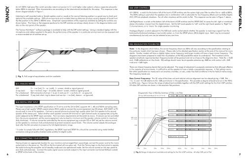
An A/V 80Hz high pass filter switch provides instant conversion to 5.1 and higher order systems where a separate subwoofer<br />
below 80Hz is required. Filter characteristics are according to the international standards for this setup. This response is also<br />
shown diagramatically in Figure 1.<br />
Listening to well recorded male or female spoken word or vocals at the normal listening position is a good way to check and<br />
optimise the available settings. Difficult environments and variable listening distances produce varying degrees of boost from<br />
the flat position in the 50Hz to 800Hz area. Graphical representations of the responses available by setting the switches are<br />
shown below. The linear or flat response positions for the DIP switches are always clearly shown in the diagrams below and<br />
also on the rear panel of the speaker.<br />
The <strong>Tannoy</strong> ActivAssist software package is available to help with the DIP switch settings. Using a standard laptop with the<br />
microphone and cables supplied in the pack, the performance of the speaker in a particular environment can be assessed and<br />
a recommended set of switches set up.<br />
3.4: USER CONTROLS<br />
A/V (80Hz): a switch to the bottom left of the bank of DIP switches sets the system high pass filter to either flat or –6dB at 80Hz.<br />
The 80Hz setting is used when the speakers are in combination with a subwoofer for low frequency effects such as Dolby Digital,<br />
AC3, DTS etc playback situations. For all other situations set this switch to flat. This response can be seen in Figure 1 above.<br />
Left/Right/Mono: a switch at the bottom left of the bank of DIP switches sets the SPDIF DAC to sense the left, right or combined<br />
stereo information (mono) from the digital stream. Set the left hand speaker to ‘Left’ and the right hand speaker to ‘Right’ for<br />
2 channel stereo, or to ‘mono’ for single speaker monitoring.<br />
Analogue/Digital: a switch adjacent to the XLR/Jack combi socket selects whether the speaker is receiving a signal from the<br />
balanced/unbalanced analogue input combi socket, or, from the SPDIF phono (RCA) digital input. Both may be connected<br />
simultaneously but only one can be selected at any one time.<br />
4.0: EQUALISATION POSSIBILITIES<br />
+3dB<br />
+1.5dB Large Medium Normal +1.5dB +2dB<br />
+0.75dB<br />
+1dB<br />
0dB Flat Flat Flat Flat<br />
-2dB -0.75dB -1dB<br />
-1dB<br />
-4dB<br />
-1.5dB<br />
-2dB<br />
-2dB<br />
-6dB<br />
-3dB<br />
-8dB<br />
-3dB<br />
( AV 80Hz HiPass on slide switch)<br />
Fig. 1. Full range of equalisation and trim available.<br />
3.1: ANALOG INPUT<br />
XLR:<br />
2= +ve (hot), 3= -ve (cold), 1= screen, shield or signal ground.<br />
3 way Jack: tip=+ve (hot), ring= -ve (cold), sleeve= screen, shield or signal ground.<br />
For unbalanced XLR connection short pin 1 to pin 3 and use 2= +ve (hot), 3= -ve (ground).<br />
For unbalanced 3 way Jack short ring to sleeve and use tip= +ve (hot), sleeve= -ve (ground).<br />
Note: In the diagrams which follow, the corner frequency shown as 50Hz will vary according to the specification relating to<br />
the particular model which has been chosen. Please refer to the detailed specification section at the end of this manual for more<br />
details. Smaller models will have a slightly higher corner frequency and larger models will have a lower corner frequency. The<br />
diagrams have been prepared to make the visualisation of the EQ possibilities easier to understand. The transitions of the<br />
speaker amplitude response bewteen frequency bands will be gradual and not as sharp as the diagrams show. Note the +10dB<br />
and -10dB calibrations on the charts. EQ settings should never be at opposite extremes eg -8dB low mid contour with -2dB<br />
mids and +3dB highs.<br />
There are 4 basic frequency bands that can be adjusted. The range of adjustment is purposely restricted so that although effective<br />
in the majority of environments, it is difficult to set the speaker to have a totally unacceptable response. A 'flat' setting means<br />
flat within specification as measured in an anechoic chamber, on axis, under free field conditions in the far field (3 metres away).<br />
The frequency bands are:<br />
Bass Corner Frequency: The 'Q' value of the bass unit and cabinet volume alignment can be altered giving +3dB, flat, -<br />
1.5, -3, and -4.5 dB relative to the -3dB point shown in the specification. This provides a degree of boost and cut in the 45Hz<br />
to 65Hz area. Figure 2 shows the range of adjustment available together with the DIP switch settings for the first 4 DIP switches.<br />
All other DIP switches are shown in the anechoic flat positions.<br />
Diagramatic View of EQ Dip Switches: LF EQ + Av Filter<br />
20 way DIP Switch Bank (4+4+2+4+6)<br />
LF EQ Low Mids Hz Up Mids<br />
Highs<br />
3.2: DIGITAL SPDIF INPUT<br />
The input impedance is the SPDIF specification at 75 ohms and the 24 bit DAC supports 44.1, 48 and 96kHz sampling rates.<br />
Please use a high quality* SPDIF coaxial phono (RCA) cable to connect the source equipment (eg CD player, DAT/ADAT or PC<br />
sound card) to one of the speakers. Connect a second (phono to phono) high quality cable from this speaker to the second<br />
speaker of the stereo pair. Select whether each speaker converts left channel or right channel audio as appropriate using the<br />
switch adjacent to the SPDIF input connector. For true mono requirements set the switch to mono. If volume can be controlled<br />
from the source equipment, set the source equipment volume level to minimum and the speaker volume control to maximum<br />
(fully clockwise). If volume cannot be controlled by the source equipment (eg a simple CD or DAT etc) set the volume control<br />
on the speaker to minimum (fully anticlockwise) to prevent excessive sound levels. The volume control adjusts the analogue<br />
level after the DA converters to preserve the full digital dynamic range.<br />
+10dB<br />
0dB re 2.8v<br />
@ 1 metre<br />
-10dB<br />
1 1 1 1 1 1 1 0 0 0 0 0 0 0 0 0 0 0 0 0<br />
1 1 1 0 1 1 1 0 0 0 0 0 0 0 0 0 0 0 0 0<br />
1 1 0 0 1 1 1 0 0 0 0 0 0 0 0 0 0 0 0 0<br />
1 0 0 0 1 1 1 0 0 0 0 0 0 0 0 0 0 0 0 0<br />
* In order to comply fully with EMC regulations, the SPDIF input and SPDIF thru should be connected using metal-shelled<br />
connectors and good quality shielded cable suitable for digital audio.<br />
0 0 0 0 1 1 1 0 0 0 0 0 0 0 0 0 0 0 0 0<br />
3.3: CONNECTING YOUR SPEAKERS<br />
80Hz AV Filter (AV on/off)<br />
Having chosen an appropriate location for your monitors and arranged them accordingly, connect the power cord to the mains<br />
socket and turn the power on. The LED on the front panel will now glow red. Push the <strong>Tannoy</strong> logo on the front panel to operate<br />
the switch to bring the amplifier out of standby mode and into operational mode. Set the volume control on the rear panel to<br />
zero (fully anticlockwise). Connect the audio signal source (console output) to the input connector (combined XLR/jack socket)<br />
or SPDIF at the back of the monitor.<br />
10Hz 20Hz<br />
50Hz 100Hz 200Hz 500Hz 1Khz 2kHz 5kHz 10kHz 20kHz<br />
Fig. 2. Range of adjustment available and settings for the first 4 DIP switches. All other DIPs set to 'Flat'<br />
6 7