Dewalt - DW742 - Electric Flipover Saw
Dewalt - DW742 - Electric Flipover Saw
Dewalt - DW742 - Electric Flipover Saw

You also want an ePaper? Increase the reach of your titles
YUMPU automatically turns print PDFs into web optimized ePapers that Google loves.
11 10<br />
12<br />
13<br />
14<br />
15<br />
9<br />
8<br />
6<br />
7<br />
16<br />
17<br />
5<br />
4<br />
18 19<br />
1<br />
A1<br />
2<br />
3<br />
20<br />
27<br />
28<br />
26<br />
21<br />
22<br />
24<br />
A2<br />
25<br />
23
30 29<br />
31<br />
33<br />
32<br />
A3<br />
36<br />
37 38 40 39<br />
42<br />
34<br />
35 41<br />
A4<br />
A5
43<br />
44<br />
35<br />
A6<br />
A7<br />
B<br />
45<br />
H<br />
B1<br />
B<br />
H<br />
A8<br />
B2
3<br />
4<br />
52<br />
48<br />
49<br />
50<br />
51<br />
C<br />
D<br />
56<br />
54<br />
53<br />
22<br />
56<br />
E1<br />
26<br />
19<br />
E2<br />
57<br />
F1<br />
F2
21 61<br />
50 16<br />
66<br />
F3<br />
63 9 65<br />
G<br />
H<br />
76 75 68 67<br />
67 68 75 76<br />
24<br />
8<br />
0°<br />
72<br />
J<br />
69 70 71 24<br />
K1<br />
73<br />
K2<br />
73<br />
74<br />
72<br />
L1<br />
77<br />
45°<br />
L2<br />
71<br />
M1
7<br />
27<br />
79<br />
M2 N1 N2<br />
19 26<br />
59<br />
30<br />
30 82 80 81 29<br />
2 mm<br />
3-8 mm<br />
O<br />
P<br />
88 87<br />
33<br />
84<br />
Q<br />
85<br />
86<br />
83<br />
R<br />
S<br />
T
24<br />
U<br />
V<br />
W<br />
X1<br />
93 93<br />
90 89<br />
X2<br />
92 91<br />
X3 Y
FLIP-OVER SAW <strong>DW742</strong><br />
ENGLISH<br />
Congratulations!<br />
You have chosen a DEWALT product. Years of experience, thorough<br />
product development and innovation make DEWALT one of the most<br />
reliable partners for professional users.<br />
Table of contents<br />
Technical data en - 1<br />
EC-Declaration of conformity en - 1<br />
Safety instructions en - 2<br />
Package contents en - 3<br />
Description en - 3<br />
<strong>Electric</strong>al safety en - 4<br />
Mains plug replacement (U.K. & Ireland only) en - 4<br />
Using an extension cable en - 4<br />
Assembly and adjustment en - 4<br />
Instructions for use en - 6<br />
Maintenance en - 8<br />
Guarantee en - 8<br />
Technical data<br />
<strong>DW742</strong><br />
Voltage V 230<br />
(U.K. & Ireland only) V 230/115<br />
(Latin America only) V 120<br />
Motor power (input) W 1,650<br />
Motor power (output) W 1,100<br />
Blade diameter mm 250<br />
Blade bore mm 30<br />
Max cycle of use load/no load min 1/3<br />
No-load speed (50/60 Hz) min -1 3,000/3,600<br />
<strong>Saw</strong> head pre-set locations left/right ° 0-45<br />
Bevel adjustment ° 0-45<br />
Cutting capacities<br />
see under “Description”<br />
Weight kg 38<br />
Fuses:<br />
Europe 230 V tools 10 Amperes, mains<br />
U.K. & Ireland 230 V tools 13 Amperes, in plugs<br />
EC-Declaration of conformity<br />
<strong>DW742</strong><br />
DEWALT declares that these Power Tools have been designed in<br />
compliance with: 98/37/EEC, 89/336/EEC, 73/23/EEC, EN 61029,<br />
EN 55014-2, EN 55014, EN 61000-3-2 & EN 61000-3-3.<br />
For more information, please contact DEWALT at the address below or<br />
refer to the back of the manual.<br />
Level of sound pressure according to 86/188/EEC & 98/37/EEC,<br />
measured according to DIN 45635:<br />
<strong>DW742</strong><br />
L pA<br />
(sound pressure) dB(A)* 83<br />
L WA<br />
(acoustic power) dB(A) 96<br />
* at the operator’s ear<br />
Take appropriate measures for the protection of hearing if the<br />
sound pressure of 85 dB(A) is exceeded.<br />
Weighted root mean square acceleration value according to DIN 45675:<br />
TÜV Rheinland<br />
Product and Safety GmbH (TRPS)<br />
Am Grauen Stein 1<br />
D-51105 Köln<br />
Germany<br />
Director Engineering and Product Development<br />
Horst Großmann<br />
<strong>DW742</strong><br />
-<br />
Cert. No.<br />
BM 9910081 01<br />
The following symbols are used throughout this manual:<br />
Denotes risk of personal injury, loss of life or damage to the<br />
tool in case of non-observance of the instructions in this<br />
manual.<br />
Denotes risk of electric shock.<br />
Sharp edges.<br />
DEWALT, Richard-Klinger-Straße 40,<br />
D-65510, Idstein, Germany<br />
18 en - 1
ENGLISH<br />
Safety instructions<br />
When using Power Tools, always observe the safety regulations<br />
applicable in your country to reduce the risk of fire, electric shock<br />
and personal injury. Read the following safety instructions before<br />
attempting to operate this product. Keep these instructions in a safe<br />
place!<br />
General<br />
1 Keep work area clean<br />
Cluttered areas and benches can cause accidents.<br />
2 Consider work area environment<br />
Do not expose Power Tools to humidity. Keep work area well lit. Do<br />
not use Power Tools in the presence of flammable liquids or gases.<br />
3 Guard against electric shock<br />
Prevent body contact with earthed surfaces (e.g. pipes, radiators,<br />
cookers and refrigerators).<br />
For use under extreme conditions (e.g. high humidity, when metal<br />
swarf is being produced, etc.) electric safety can be improved by<br />
inserting an isolating transformer or a (FI) earth-leakage circuit-breaker.<br />
4 Keep children away<br />
Do not let children come into contact with the tool or extension cord.<br />
Supervision is required for those under 16 years of age.<br />
5 Extension cords for outdoor use<br />
When the tool is used outdoors, always use extension cords intended<br />
for outdoor use and marked accordingly.<br />
6 Store idle tools<br />
When not in use, Power Tools must be stored in a dry place and<br />
locked up securely, out of reach of children.<br />
7 Dress properly<br />
Do not wear loose clothing or jewellery. They can be caught in moving<br />
parts. Preferably wear rubber gloves and non-slip footwear when<br />
working outdoors. Wear protective hair covering to keep long hair out<br />
of the way.<br />
8 Wear safety goggles<br />
Also use a face or dust mask in case the operations produce dust or<br />
flying particles.<br />
9 Beware of maximum sound pressure<br />
Take appropriate measures for the protection of hearing if the sound<br />
pressure of 85 dB(A) is exceeded.<br />
10 Secure workpiece<br />
Use clamps or a vice to hold the workpiece. It is safer and it frees both<br />
hands to operate the tool.<br />
11 Do not overreach<br />
Keep proper footing and balance at all times.<br />
12 Avoid unintentional starting<br />
Do not carry the plugged-in tool with a finger on the switch. Be sure<br />
that the switch is released when plugging in.<br />
13 Stay alert<br />
Watch what you are doing. Use common sense. Do not operate the<br />
tool when you are tired.<br />
14 Disconnect tool<br />
Shut off power and wait for the tool to come to a complete standstill<br />
before leaving it unattended. Unplug the tool when not in use, before<br />
servicing or changing accessories.<br />
15 Remove adjusting keys and wrenches<br />
Always check that adjusting keys and wrenches are removed from the<br />
tool before operating the tool.<br />
16 Use appropriate tool<br />
The intended use is described in this instruction manual. Do not force<br />
small tools or attachments to do the job of a heavy-duty tool. The tool<br />
will do the job better and safer at the rate for which it was intended.<br />
Warning! The use of any accessory or attachment or performance of<br />
any operation with this tool, other than those recommended in this<br />
instruction manual may present a risk of personal injury.<br />
17 Do not abuse cord<br />
Never carry the tool by its cord or pull it to disconnect from the socket.<br />
Keep the cord away from heat, oil and sharp edges.<br />
18 Maintain tools with care<br />
Keep the tools in good condition and clean for better and safer<br />
performance. Follow the instructions for maintenance and changing<br />
accessories. Inspect the tool cords at regular intervals and, if<br />
damaged, have them repaired by an authorized DEWALT repair agent.<br />
Inspect the extension cords periodically and replace them if damaged.<br />
Keep all controls dry, clean and free from oil and grease.<br />
19 Check for damaged parts<br />
Before using the tool, carefully check it for damage to ensure that it will<br />
operate properly and perform its intended function. Check for<br />
misalignment and seizure of moving parts, breakage of parts and any<br />
other conditions that may affect its operation. Have damaged guards<br />
or other defective parts repaired or replaced as instructed.<br />
Do not use the tool if the switch is defective. Have the switch replaced<br />
by an authorized DEWALT repair agent.<br />
20 Have your tool repaired by an authorized DEWALT repair agent<br />
This Power Tool is in accordance with the relevant safety regulations.<br />
To avoid danger, electric appliances must only be repaired by qualified<br />
technicians.<br />
Additional safety rules for flip-over saws<br />
• Do not use the saw to cut other than aluminium, wood or similar materials.<br />
• Connect the machine to a dust collection device when sawing wood.<br />
• Select the correct saw blade for the material to be cut.<br />
• Use correctly sharpened blades. Observe the maximum speed marked<br />
on the sawblade.<br />
• Use only saw blades recommended by the manufacturer and which<br />
conform to EN847-1.<br />
• Make sure the floor area around the machine is level, well maintained<br />
and free of loose materials e.g. chips and off-cuts.<br />
• Make sure adequate general or localized lighting is provided.<br />
• Wear suitable personal protective equipment when necessary, including:<br />
- hearing protection to reduce the risk of induced hearing loss;<br />
- respiratory protection to reduce the risk of inhalation of harmful dust;<br />
- gloves for handling saw blades and rough material. <strong>Saw</strong> blades<br />
should be carried in a holder wherever practicable.<br />
• Refrain from removing any cut-offs or other parts of the workpiece from<br />
the cutting area whilst the saw is running and the saw head is not in<br />
the rest position.<br />
• Replace the table insert when worn.<br />
• Report faults in the machine, including guards or sawblades,<br />
to your dealer as soon as they are discovered.<br />
• Ensure that the upper portion of the saw blade is completely enclosed<br />
in the mitre sawing mode. Do not use the saw without the guards in<br />
position, in good working order and properly maintained.<br />
• Ensure that the arm is securely fixed in the working position in the<br />
bench sawing mode.<br />
• Ensure that the arm is securely fixed when bevelling in the bench saw<br />
mode.<br />
• Take care when grooving during the bench saw operation by using<br />
appropriate guarding system. Slotting is not allowed.<br />
Additional safety rules for mitre saws<br />
• Make sure that the blade rotates in the correct direction. Keep the<br />
blade sharp. Do not use blades of larger or smaller diameter than<br />
recommended. For the proper blade rating refer to the technical data.<br />
• Make sure all locking knobs and clamp handles are tight before starting<br />
any operation.<br />
• Check periodically that the motor air slots are clean and free of chips.<br />
• Disconnect the machine from the mains before carrying out any<br />
maintenance work or when changing the blade.<br />
• Before using any accessory consult the instruction manual.<br />
The improper use of an accessory can cause damage.<br />
en - 2 19
ENGLISH<br />
• Allow the motor to reach full speed before cutting.<br />
• Raise the blade from the kerf in the workpiece prior to releasing the<br />
switch.<br />
• Do not wedge anything against the fan to hold the motor shaft.<br />
• Never place either hand in the blade area when the saw is connected<br />
to the electrical power source.<br />
• Do not attempt to cut excessively small pieces.<br />
• Never attempt to stop a machine in motion rapidly by jamming a tool or<br />
other means against the blade; serious accidents can be caused<br />
unintentionally in this way.<br />
• Do not use cracked or damaged saw blades.<br />
• Do not use any abrasive discs.<br />
Additional safety rules for saw benches<br />
• Make sure that the blade rotates in the correct direction and that the<br />
teeth are pointing to the front of the saw bench.<br />
• Be sure all clamp handles are tight before starting any operation.<br />
• Be sure all blade and flanges are clean and the recessed sides of the<br />
collar are against the blade. Tighten the arbor nut securely.<br />
• Keep the saw blade sharp and properly set.<br />
• Make sure that the riving knife is adjusted to the correct distance form<br />
the blade - 3-8 mm.<br />
• Never operate the saw without the upper and lower guards in place.<br />
• Keep your hands out of the path of the saw blade.<br />
• Disconnect the saw from the mains supply before changing blades or<br />
carrying out maintenance.<br />
• Use a push stick at all times, and ensure that you do not place hands<br />
closer than 150 mm from the saw blade while cutting.<br />
• Do not attempt to operate on anything but the designated voltage.<br />
• Do not apply lubricants to the blade when it is running.<br />
• Do not reach around behind the saw blade.<br />
Residual risks<br />
The following risks are inherent to the use of this saw:<br />
- Injuries caused by touching the rotating parts<br />
In spite of the application of the relevant safety regulations and the<br />
implementation of safety devices, certain residual risks cannot be<br />
avoided. These are:<br />
- Impairment of hearing.<br />
- Risk of accidents caused by the uncovered parts of the rotating saw<br />
blade.<br />
- Risk of injury when changing the blade.<br />
- Risk of squeezing fingers when opening the guards.<br />
- Health hazards caused by breathing dust developed when sawing<br />
wood, especially oak, beech and MDF.<br />
Package contents<br />
The package contains:<br />
1 Partly assembled machine<br />
4 Legs<br />
1 Top guard for bench saw position<br />
1 Under-table guard for mitre saw position<br />
1 Plastic bag containing:<br />
1 pin spanner<br />
1 Allen key 6 mm<br />
1 Skinpack containing:<br />
1 dual height rip fence (DE3743)<br />
1 push stick<br />
1 30 teeth TCT saw blade<br />
1 Instruction manual<br />
1 Exploded drawing<br />
• Check for damage to the tool, parts or accessories which may have<br />
occurred during transport.<br />
• Take the time to thoroughly read and understand this manual prior to<br />
operation.<br />
• Remove the saw from the packaging material carefully.<br />
Description (fig. A1 - A4)<br />
Your DEWALT flip-over sawing machine has been designed to operate as a<br />
mitre saw or as a saw bench to perform the four main sawing operations of<br />
ripping, cross-cutting, bevelling and mitring easily, accurately and safely,<br />
using the following materials: wood, wood products, aluminium and plastic.<br />
Mitre saw mode<br />
In mitre saw mode, the sawing machine is used in vertical, mitre or bevel<br />
position.<br />
<strong>Saw</strong> bench mode<br />
Turned over on its central axis, the sawing machine is used to perform the<br />
standard ripping operation and for sawing wide pieces by manually<br />
feeding the workpiece into the blade.<br />
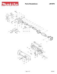
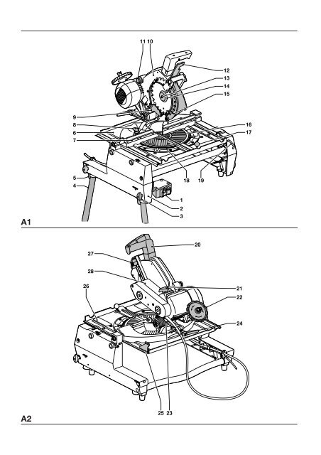
A1<br />
1 On/off-switch<br />
2 Side panel<br />
3 Leg clamping wingnut<br />
4 Leg<br />
5 Foot<br />
6 Mitre saw table<br />
7 Fence<br />
8 Rotating table location plunger<br />
9 Fixed lower rear guard<br />
10 Fixed upper blade guard<br />
11 Dust extraction adapter<br />
12 Head lock release lever<br />
13 Blade bolt<br />
14 Outer flange<br />
15 Moving lower guard<br />
16 Rotating table<br />
17 Rotating table clamp<br />
18 Mitre scales<br />
19 Table release lever<br />
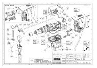
A2<br />
20 Control handle<br />
21 Depth stop rod<br />
22 Height adjuster<br />
23 Dust extraction adapter<br />
24 Bevel clamp handle<br />
25 <strong>Saw</strong> table retention bracket<br />
26 Table locking device<br />
27 Riving knife clamp knob<br />
28 Motor housing<br />
<strong>Saw</strong> bench mode<br />
A3<br />
29 Upper blade guard<br />
30 Riving knife<br />
31 <strong>Saw</strong> bench table<br />
32 Mitre fence (optional)<br />
33 Dual height parallel fence<br />
Optional accessories<br />
For use in mitre saw mode:<br />
A3<br />
32 Mitre fence (DE3496)<br />
20 en - 3
ENGLISH<br />
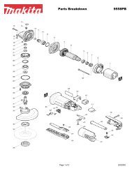
A4<br />
34 Adjustable stand 760 mm (max. height) (DE3474)<br />
35 Support guide rails 1,000 mm (DE3494)<br />
35 Support guide rails 500 mm (DE3491)<br />
36 Inclinable support (DE3495)<br />
37 Swivelling stop (DE3462)<br />
38 Length stop for short workpieces (to be used with guide rails [35])<br />
(DE3460)<br />
39 Support with removable stop (DE3495)<br />
40 Support with stop removed (DE3495)<br />
41 Material clamp (DE3461)<br />
• Only fit 13 Amperes BS1363A approved plugs fitted with the correctly<br />
rated fuse (1).<br />
• The cable wire colours, or a letter, will be marked at the connection<br />
points of most good quality plugs. Attach the wires to their respective<br />
points in the plug (see below). Brown is for Live (L) (2), blue is for<br />
Neutral (N) (4) and green/yellow is for Earth (E).<br />
• Before replacing the top cover of the mains plug ensure that the cable<br />
restraint (3) is holding the outer sheath of the cable firmly and that the<br />
leads are correctly fixed at the terminal screws.<br />
A5<br />
42 Roller support table (DE3497)<br />
For use in saw bench mode:<br />
A6<br />
43 Extension table (DE3472)<br />
A7<br />
44 Single sliding table (DE3471)<br />
Push sticks (DE3454) (not shown)<br />
For use in all modes:<br />
A8<br />
45 Three way dust extraction kit (DE3500)<br />
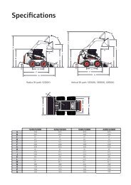
Cutting capacities<br />
Cutting capacity in mitre saw mode<br />
Cutting angle Size of material Notes<br />
H mm B mm<br />
Straight cross-cut 20 180 No packaging piece required<br />
30 176<br />
40 170<br />
68 140<br />
85 68 With 25 mm packaging piece (fig. B1)<br />
88 22 With 50 mm packaging piece (fig. B1)<br />
15 210 Thin boards only (fig. B2)<br />
Table turned 45° to<br />
right for mitre cuts 70 95 Cross-cut at max. height<br />
Table turned 45° to<br />
left for mitre cuts 68 93 Cross-cut at max. height<br />
<strong>Saw</strong>head tilted 45°<br />
for bevel cuts 50 140<br />
Cutting capacity in saw bench mode<br />
Cutting depth adjustment<br />
90° vertical cut 0 - 70 mm<br />
45° bevel cut 0 - 32 mm<br />
<strong>Electric</strong>al safety<br />
The electric motor has been designed for one voltage only. Always check<br />
that the power supply corresponds to the voltage on the rating plate.<br />
Mains plug replacement (U.K. & Ireland only)<br />
• Should your mains plug need replacing and you are competent to do<br />
this, proceed as instructed below. If you are in doubt, contact an<br />
DEWALT authorized repair agent or a qualified electrician.<br />
• Disconnect the plug from the supply.<br />
• Cut off the plug and dispose of it safely; a plug with bared copper<br />
conductors is dangerous if engaged in a live socket outlet.<br />
Never use a light socket. Never connect the live (L) or neutral (N)<br />
wires to the earth pin marked E or .<br />
Using an extension cable<br />
If an extension cable is required, use an approved extension cable suitable<br />
for the power input of this machine (see technical data). The minimum<br />
conductor size is 1.5 mm 2 . When using a cable reel, always unwind the<br />
cable completely. Also refer to the table below.<br />
Conductor size (mm 2 ) Cable rating (Amperes)<br />
0.75 6<br />
1.00 10<br />
1.50 15<br />
2.50 20<br />
4.00 25<br />
Cable length (m)<br />
7.515 25 30 45 60<br />
Voltage Amperes Cable rating (Amperes)<br />
230 0 - 2.0 6 6 6 6 6 6<br />
2.1 - 3.4 6 6 6 6 6 6<br />
3.5 - 5.0 6 6 6 6 10 15<br />
5.1 - 7.0 10 10 10 10 15 15<br />
7.1 - 12.0 15 15 15 15 20 20<br />
115-120 12.1 - 20.0 20 20 20 20 25 -<br />
Assembly and adjustment<br />
Prior to assembly and adjustment always unplug the tool.<br />
The machine is packed in the saw bench mode for compactness and is<br />
fully assembled for mitre saw operation except for the legs, under-table<br />
plastic guard and blade.<br />
Fitting the legs (fig. C)<br />
• Place the machine upside down on the floor.<br />
• Loosen the four wingnuts (3) and insert a leg (4) into each of the clamps.<br />
• Tighten the wingnuts (3) and turn the table over. Make sure it is level;<br />
adjust the leg clamping height if required.<br />
Assembly for mitre saw mode<br />
Mounting the under-table guard (fig. D)<br />
The under-table guard (48) is fitted to the top of the saw bench table.<br />
• Place the two hooks on the left of the guard into the oblong slots (49)<br />
on the left of the blade slot (50).<br />
• Place the guard flat on the table and press it in the locking grommet (51).<br />
en - 4 21
ENGLISH<br />
• To remove, loosen the grommet with a screwdriver (52) and proceed in<br />
reverse order.<br />
Turning the sawhead and table over (fig. A2, E1 & E2)<br />
• Withhold the saw table with one hand and push the table release lever (19)<br />
to the left (fig. E1).<br />
• Push the table downwards at the front and swing it over completely<br />
until the motor assembly is uppermost and the indentation engages in<br />
the retaining teeth of the table locking device (26).<br />
• The head assembly is held down by a clamp strap at the front and a<br />
height adjuster (22) at the rear (fig. A2).<br />
• Remove the strap.<br />
• Rotate the circular wheel (53) counterclockwise whilst holding down<br />
the head until the “U”-shaped bracket (54) can be disengaged from its<br />
seating (fig. E2).<br />
• Swing the height adjuster up and push the rod (55) into the clip (56).<br />
• Holding the head firmly, allow the spring pressure to take the head<br />
upwards into its rest position.<br />
Mounting the saw blade (fig. A1, F1 - F3)<br />
• The teeth of a new blade are very sharp and can be dangerous.<br />
• Always change blades with the machine in mitre saw mode.<br />
• The maximum diameter blade that can be fitted is 250 mm.<br />
The minimum diameter is 244 mm.<br />
• Loosen the riving knife clamping knob (27) and allow the riving knife (30)<br />
to swing downwards (fig. F1).<br />
• Place the 6 mm Allen key into the end of the blade bolt (13) and the<br />
two pins of the pin spanner (57) into the holes on the outer flange (14).<br />
• The blade bolt has a left-handed thread, therefore holding the spanner<br />
firmly, turn the Allen key clockwise to loosen.<br />
• Remove the blade bolt (13) and remove the outer flange (14).<br />
• If the blade bolt is too tight, turn the handle of the pin spanner (57) into<br />
the guard and lock it there using a screwdriver (58) (fig. F2). This allows<br />
to exert extra pressure on the Allen key.<br />
• The blade (59) has a 30 mm bore, and is located on a step flange (60)<br />
on the inner flange (61) (fig. F1).<br />
• Press the guard retraction lever (12) and move the head down slightly<br />
to release the lower guard (15) (fig. A1).<br />
• Rotate the lower blade guard all the way up and hold it there.<br />
• Make sure the inner flange and both faces of the blade are clean and<br />
free of dust.<br />
• Place the blade onto the step flange (60) on the inner flange (61),<br />
ensuring that the teeth are pointing downwards (fig. F1).<br />
• Carefully ease the blade into position and release the lower blade guard.<br />
• Also ensure that the two projections (62) on the outer collar are seated<br />
properly through the inner collar and onto the flats on the spindle.<br />
• Tighten the blade bolt securely.<br />
• Rotate the blade by hand to check that it rotates freely. If it fouls the<br />
lower rear blade guard (9), retighten the crosshead screws (63) (fig. F3).<br />
• Reposition the riving knife (30) in the upper rest position and tighten the<br />
clamping knob (27) (fig. F1).<br />
Adjusting the mitre saw mode depth limiter (fig. G)<br />
The handle (64) is connected to a depth stop rod (21) which has an<br />
eccentrically positioned adjustable bolt (65) with locknut (66). When the depth<br />
limiter is engaged, the saw head cannot be pulled down completely (fig. G).<br />
- Handle to the left = engaged, for use in mitre saw mode<br />
(all angles except 0-45° mitre cross cut)<br />
- Handle to the right = disengaged, for use in saw bench mode<br />
• If the depth limiter needs adjustment, loosen the locknut (66)<br />
and screw the bolt (65) in or out as required.<br />
Incorrect use of the depth limiter may cause damage to the<br />
machine.<br />
Adjusting the mitre angle in mitre saw mode (fig. A1, A2 & H)<br />
The straight cross-cut and 45° mitre positions are pre-set.<br />
• Lift the rotating table clamp (17), pull up the rotating table location<br />
plunger (8) and rotate it counterclockwise a quarter of a turn (fig. A1).<br />
• Grip the control handle (20) (fig. A1), compress the guard retraction<br />
lever (12) and lower the saw about halfway (fig. A2).<br />
• Turn the sawhead with its rotating table to the required position.<br />
• Push down the rotating table clamp (17). The rotating table location<br />
plunger (8) will engage automatically (fig. A1).<br />
Using the red marks (67), the rotating table (16) can be set to any mitre<br />
angle left or right between 0° and 45° (fig. H):<br />
- angles between 0° and 30°: use the red marks nearest to the slot<br />
- angles between 30° and 45°: use the outer red mark (68)<br />
• Proceed as for pre-set positions. The rotating table location plunger<br />
cannot be used for intermediate angles.<br />
Always make a trial cut in a piece of waste wood, to check for<br />
accuracy.<br />
Adjusting the bevel position (fig. J)<br />
The sawhead can be tilted from the vertical position to 45° left to enable<br />
bevel cuts to be made at any angle between these two limits.<br />
• Standing behind the machine, release the bevel clamp handle (24)<br />
(it allows a ratchet-type action when full rotation of the handle is not<br />
possible).<br />
• Tilt the sawhead to the required angle on the bevel scale (69).<br />
The pointer (70) is on the fixed cast part of the bevel bracket (71).<br />
• Tighten the bevel clamp handle (24) and leave it in horizontal position.<br />
Checking and adjusting the blade to the fence (fig. H2, K1 & K2)<br />
• With the head in the vertical position and the bevel clamp handle (24)<br />
released and raised, slacken the locking screw (72) in the rear of the<br />
rotating table location plunger (8) (fig. K1).<br />
• Place a set square (73) against the fence and along the blade as<br />
shown in figure K2. The angle should be 90°.<br />
• If adjustment is required, rotate the eccentric adjustment bush (74) until<br />
the face of the saw blade is flat against the square (fig. K2).<br />
• Tighten the locking screw (72).<br />
• Check that the red marks (67) nearest the blade slot (50) are in line with<br />
the 0° position (75) on the two scales (fig. H).<br />
• If adjustment is required, loosen the screws (76) and bring the<br />
indicators in line. The 45° position should now also be accurate.<br />
If this is not the case, the blade is not perpendicular to the rotating<br />
table (see below).<br />
Adjusting the blade vertical to the rotating table (fig. L1 & L2)<br />
• Ensure that the sawhead is to its extreme right-hand position with the<br />
bevel clamp handle locked.<br />
• Release and retract the lower guard.<br />
• Place a set square (73) on the rotating table and up against the blade<br />
(fig. L1).<br />
• If adjustment is required, proceed as follows:<br />
• Adjust the grub screw (77) as required. The grub screw is self-locking<br />
(fig. L2).<br />
Checking and adjusting the 45° bevel position in mitre mode<br />
(fig. M1 & M2)<br />
• Ensure that the sawhead is to its extreme left-hand position with the<br />
bevel clamp handle locked.<br />
• Release and retract the lower guard.<br />
• Check the angle from the blade to the table with a suitable protractor.<br />
It should be 45° (fig. M1).<br />
22 en - 5
ENGLISH<br />
• If adjustment is required, proceed as follows:<br />
• Adjust the grub screw (78) as required. The grub screw is self-locking<br />
(fig. M2).<br />
Assembly for saw bench mode<br />
Changing from mitre saw to saw bench mode<br />
(fig. A1, A3, E2, G, N1 & N2)<br />
Check that the depth limiter is disengaged. Refer to the<br />
section “Adjusting the mitre saw mode depth limiter (fig. G)”.<br />
• Put the blade into 0° cross-cut position with the rotating table location<br />
plunger (8) correctly located and the rotating table clamp (17) secured<br />
(fig. A1).<br />
• Slacken the riving knife clamp knob (27) just enough to allow the riving<br />
knife to swing downwards (fig. N1).<br />
• Slide the riving knife bracket (79) to the right so that the narrow part on<br />
the right locates in the slot provided in the casting and tighten the<br />
clamp knob.<br />
• Remove the under-table guard.<br />
• Pull down the sawhead and swing the height adjuster (22) until its<br />
U-shaped bracket (54) engages on the pin provided in the base (fig. E2).<br />
• Turn the wheel (53) of the adjuster to make the blade and riving knife<br />
protrude from the saw bench table (31) (fig. A3) to provide maximum<br />
cutting depth in saw bench mode.<br />
The blade should not foul the lower blade guard.<br />
• Pull the table release lever (19) to the left, lift the front edge of the table and<br />
flip it back through 180° until the teeth of the table-locking device (26)<br />
automatically engage the saw blade retention lever to secure it in the<br />
saw bench mode (fig. N2).<br />
Adjusting the riving knife (fig. A2, F3 & O)<br />
In the mitre saw mode, the riving knife (30) must be adjusted up and out of<br />
the way by unscrewing the clamp knob (27) and moving the riving knife<br />
until it can be rotated up (fig. F3).<br />
In the saw bench mode, the correct position is for the top of the riving<br />
knife (30) to be no more than 2 mm below the highest tooth of the blade (59)<br />
and the body of the radius to be a maximum of 3-8 mm from the tips of<br />
the saw blade teeth. Also the riving knife must be completely in line with<br />
the rear of the saw blade (fig. O).<br />
• If adjustment is required, proceed as follows:<br />
• Unlock the clamp knob (27), slide the knob forwards or backwards in<br />
its slot and tighten the clamp knob (fig. A2).<br />
• The bracket securing the riving knife to the machine must be at<br />
least 3 mm away from the blade teeth.<br />
• Always check that the riving knife clamp knob is tightly secured.<br />
Fitting the upper blade guard (fig. P)<br />
The upper blade guard (29) is designed to be quickly and easily attached,<br />
via a spring-loaded plunger (80) to the hole (81) in the riving knife (30) once<br />
it has been positioned through the worktable for saw bench mode.<br />
• Secure the upper blade guard (29) to the riving knife by pulling the<br />
knob (82) to allow the plunger in the guard to engage.<br />
Never use your saw in saw bench mode without the upper<br />
guard correctly fitted.<br />
Mounting and adjusting the parallel fence (fig. Q)<br />
The dual height parallel fence (33) can be used in two positions (10 or 62 mm).<br />
The parallel fence can be mounted on either side of the blade. To turn the<br />
fence into the appropriate position, proceed as follows:<br />
• Loosen the knob.<br />
• Pull out the bracket (84) and replace it on the other end.<br />
• Slide the bracket on from the left or the right. The clamping plate (85)<br />
engages behind the front edge of the table.<br />
• Check that the fence is parallel to the blade. If not, then adjust as follows.<br />
• Loosen the Allen screw (86).<br />
• Adjust the fence so that it is parallel to the blade by checking the distance<br />
between the blade and the fence at the front and rear of the blade.<br />
• When the adjustment has been carried out, re-tighten the Allen screw<br />
and check again that the fence is parallel to the blade.<br />
• Tighten the knob (83).<br />
• Use the 10 mm profile for ripping low workpieces to allow<br />
access between the blade and the fence for the push stick.<br />
• The rear end of the fence should be level with the front of the<br />
riving knife.<br />
Changing from saw bench to mitre saw mode (fig. D, E1 & E2)<br />
• Remove the parallel fence (33).<br />
• Turn the wheel (53) of the height adjuster (22) to provide maximum<br />
cutting depth in mitre saw mode (fig. E2).<br />
• Proceed as described in the section “Turning the sawhead and table<br />
over (fig. E1 & E2)”.<br />
• Adjust the riving knife up and out of the way.<br />
• Replace the under-table guard (48) (fig. D).<br />
Remember to use the depth stop limiter for all angles except<br />
0-45° mitre cross cut.<br />
Instructions for use<br />
• Always observe the safety instructions and applicable regulations.<br />
• The attention of UK users is drawn to the “woodworking<br />
machines regulations 1974” and any subsequent amendments.<br />
• Ensure the material to be sawn is firmly secured in place.<br />
• Apply only a gentle pressure to the tool and do not exert side<br />
pressure on the saw blade.<br />
• Avoid overloading.<br />
Prior to operation:<br />
• Install the appropriate saw blade. Do not use excessively worn blades.<br />
The maximum rotation speed of the tool must not exceed that of the<br />
saw blade.<br />
• Do not attempt to cut excessively small pieces.<br />
• Allow the blade to cut freely. Do not force.<br />
• Allow the motor to reach full speed before cutting.<br />
• Make sure all locking knobs and clamp handles are tight.<br />
Switching on and off (fig. A1 & R)<br />
The on/off switch has a no-volt release function: should the power be shut<br />
off for some reason, the switch has to be deliberately reactivated.<br />
• To switch the machine on, press the green start button (87).<br />
• To switch the machine off, press the red stop button (88).<br />
Basic saw cuts<br />
<strong>Saw</strong>ing in mitre saw mode<br />
It is dangerous to operate without guarding. Guards must be in position<br />
when sawing. Always clamp the workpiece when cutting non-ferrous<br />
metals. Use the DE3461 clamp.<br />
en - 6 23
ENGLISH<br />
General handling<br />
- In the mitre saw mode, the sawhead is automatically locked in the<br />
upper “park”-position.<br />
- Squeezing the head lock release lever will unlock the sawhead.<br />
- Never seek to prevent the lower guard returning to its park position<br />
when the cut is completed.<br />
- The minimum length of offcut material is 10 mm.<br />
- When cutting short material (min. 190 mm to the left or the right of the<br />
blade), the use of the optional material clamp is recommended.<br />
- When cutting UPVC sections, a supporting piece made out of timber<br />
with a complementary profile should be placed beneath the material<br />
being cut to provide the correct level of support.<br />
Vertical straight cross cut (fig. S)<br />
• Set the rotating table to 0° and make sure that the locating plunger is<br />
engaged.<br />
• Pull down the rotating table clamping knob.<br />
• Place the wood to be cut against the fence. Take hold of the control<br />
handle and press in the head lock release lever.<br />
• Switch the machine on.<br />
• Allow the blade to cut freely. Do not force.<br />
• When the cut is completed, raise the sawhead to its rest position and<br />
press the red stop button.<br />
Do not allow the sawhead to jump back unaided to prevent<br />
damage.<br />
Mitre cuts (fig. T)<br />
• Set the required mitre angle.<br />
• Ensure that the rotating table clamp is tightly secured.<br />
• Ensure that the depth stop limiter is correctly set to prevent the blade<br />
cutting the table if the angle is not 45°.<br />
• Proceed as for a vertical straight cross-cut.<br />
Bevel cuts (fig. U)<br />
• Release the bevel clamp handle (24) and tilt the head to the angle<br />
required.<br />
• Tighten the bevel clamp handle.<br />
• Proceed as for a vertical straight cross-cut.<br />
Compound mitre<br />
This cut is a combination of a mitre and a bevel cut.<br />
The limitations are 45° mitre/30° bevel. Do not exceed these limits.<br />
• Set the bevel angle and subsequently set the mitre angle.<br />
<strong>Saw</strong>ing in the bench mode<br />
• Always ensure that the riving knife and blade guard are correctly aligned.<br />
Ripping (fig. V)<br />
• Set the blade to the correct height.<br />
• The correct blade position is to have the tips of three teeth above the<br />
top surface of the wood.<br />
• Mount the parallel fence using either the 10 mm or the 62 mm profile.<br />
The piece of wood between the fence and the blade is the retained piece.<br />
• Switch the machine on.<br />
• Slowly feed the timber underneath the front of the upper blade guard,<br />
keeping it firmly pressed against the fence. Allow the teeth to cut and<br />
do not force the timber through the blade. The blade speed should be<br />
kept constant.<br />
Always use a push stick.<br />
• When the cut is finished, switch off by pressing the red stop button.<br />
Bevel cuts (fig. W)<br />
• Release the bevel clamp handle and set the blade to the required angle.<br />
• In order to prevent material jamming between the blade and the fence,<br />
position the fence to the left of the blade.<br />
• Proceed as for vertical ripping.<br />
Mitre cuts (fig. X1 - X3)<br />
• To adjust the mitre fence, loosen the stop screw locknut (90) and<br />
screw the stop (91) in or out until the mitre pointer reads 0° (fig. X1).<br />
• Set the blade height and angle.<br />
• Insert the slide bar (92) of the mitre fence into the groove (93) provided<br />
in the left-hand side of the table (fig. X2).<br />
• Loosen the mitre locking knob (94) and rotate the fence to set the<br />
scale to the required angle (fig. X3).<br />
• Tighten the mitre locking knob (94).<br />
• Place the workpiece against the flat surface of the mitre fence.<br />
Switch on and, holding the workpiece firmly, slide the fence along the<br />
groove to take the workpiece into the blade. When the cut is<br />
completed, switch off immediately.<br />
Fence positions, saw bench mode (fig. Y)<br />
- For ripping thin materials, use the 10 mm profile of the dual height<br />
parallel fence and position the fence opposite the front edge of the<br />
riving knife.<br />
- For ripping thicker materials, use the 62 mm profile of the dual height<br />
parallel fence.<br />
- For cross-cutting narrow and short workpieces (fig. Y):<br />
• Adjust the parallel fence with the low profile facing the blade and<br />
install the rear of the fence in line with the leading edge of the blade.<br />
• Set the workpiece against the mitre fence (at 0° or 90°) and push the<br />
mitre fence to make the cut.<br />
• To prevent small offcut pieces fouling against the blade, prepare a<br />
tapered length of timber and clamp it on the rear edge of the<br />
worktable close enough to the right-hand side of the blade so that<br />
successive offcuts feed automatically to the right.<br />
- For ripping narrow (< 120 mm) and long workpieces:<br />
• Place the fence in rearmost position to maintain accuracy during<br />
long cuts.<br />
• Push the workpiece with both hands (one on each side of the blade).<br />
• Use a push stick when close to the blade.<br />
• Support long workpieces at the outfeed side.<br />
- For ripping wider (>120 mm) workpieces:<br />
• Adjust the fence forward as in figure Y if the material being cut tends<br />
to jam between the blade or the riving knife and the fence.<br />
Optional accessories<br />
Prior to assembling any accessories always unplug the machine.<br />
Dust extraction kit (fig. A1, A2 & A8)<br />
This machine is provided with three dust extraction points for use in each<br />
mode.<br />
• Whenever possible, connect a dust extraction device designed in<br />
accordance with the relevant regulations regarding dust emission.<br />
Connecting - mitre saw position<br />
• Connect one hose to the under-table guard.<br />
• Connect one hose to the small diameter outlet (11) and one to the<br />
large diameter outlet (23) using the corresponding spouts.<br />
• Connect the hoses to the 3-way connector.<br />
• Connect the single outlet of the 3-way connector to the hose from the<br />
dust extractor.<br />
24 en - 7