Leica - Runner 20
Leica - Runner 20
Leica - Runner 20
Create successful ePaper yourself
Turn your PDF publications into a flip-book with our unique Google optimized e-Paper software.
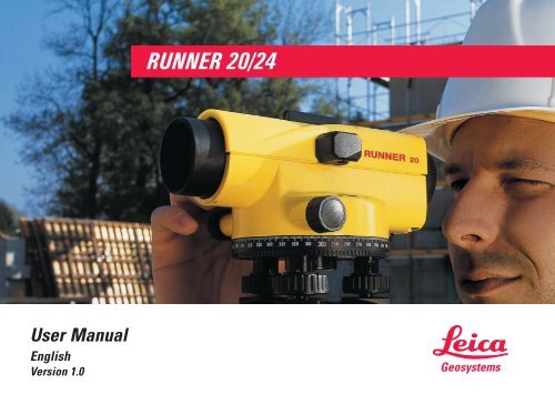
User Manual<br />
English<br />
Version 1.0<br />
RUNNER <strong>20</strong>/24
Automatic level<br />
Congratulations on your purchase of a new <strong>Leica</strong> Geosystems<br />
automatic level.<br />
This manual contains important safety directions (refer to section<br />
"Safety directions") as well as instructions for setting up the<br />
instrument and operating it.<br />
Please read this User Manual carefully to achieve maximum<br />
efficiency from your Instrument.<br />
RUNNER <strong>20</strong>/24-1.0.1en 2<br />
Automatic level
Product identification<br />
The type of your product is indicated on the label on the bottom of<br />
the base plate. The serial number is on the right side of your<br />
product.<br />
Write the type and serial number of your instrument in the space<br />
provided below, and always quote this information when you need<br />
to contact your agency or service workshop.<br />
Type:<br />
Serial no.:<br />
RUNNER <strong>20</strong>/24-1.0.1en 3<br />
Product identification
Symbols used in this manual<br />
The symbols used in this User Manual have the following<br />
meanings:<br />
DANGER:<br />
Indicates an imminently hazardous situation which, if not avoided,<br />
will result in death or serious injury.<br />
WARNING:<br />
Indicates a potentially hazardous situation or an<br />
unintended use which, if not avoided, could result in death or<br />
serious injury.<br />
CAUTION:<br />
Indicates a potentially hazardous situation or an<br />
unintended use which, if not avoided, may result in minor or<br />
moderate injury and / or appreciable material, financial and<br />
environmental damage.<br />
Important paragraphs which must be adhered to in practice as they<br />
enable the product to be used in a technically correct and efficient<br />
manner.<br />
RUNNER <strong>20</strong>/24-1.0.1en 4<br />
Symbols used in this manual
View of chapters<br />
Introduction .......................................................................... 7<br />
Measurement preparation ................................................ 10<br />
Measuring ........................................................................... 14<br />
Checking and adjusting .................................................... 19<br />
Care and Storage ............................................................... 21<br />
Safety Directions ............................................................... 24<br />
Accessories........................................................................ 31<br />
Technical Data ................................................................... 32<br />
Index.................................................................................... 33<br />
RUNNER <strong>20</strong>/24-1.0.1en 5<br />
View of chapters
Contents<br />
Introduction ............................................... 7<br />
Special features ..................................... 7<br />
Important parts ....................................... 8<br />
Technical terms and abbreviations ........ 9<br />
Measurement preparation ..................... 10<br />
Unpacking ............................................ 10<br />
Setting up the tripod............................. 11<br />
Levelling up .......................................... 12<br />
Focusing telescope .............................. 13<br />
Centring ................................................ 13<br />
Measuring ................................................ 14<br />
Height reading ...................................... 14<br />
Distance measuring ............................. 15<br />
Angle measuring .................................. 15<br />
Line levelling ........................................ 16<br />
Area levelling ....................................... 17<br />
Levelling total station measuring ......... 18<br />
Levelled stakeout ................................. 18<br />
Checking and adjusting ......................... 19<br />
Tripod ................................................... 19<br />
Circular level ........................................ 19<br />
Checking and adjusting of<br />
the line-of-sight .................................... <strong>20</strong><br />
Care and Storage .................................... 21<br />
Transport .............................................. 21<br />
In the field ................................................ 21<br />
Inside vehicle ........................................... 22<br />
Shipping ................................................... 22<br />
Storage ................................................. 22<br />
Cleaning ............................................... 23<br />
Safety Directions .................................... 24<br />
Intended use of instrument .................. 24<br />
Permitted uses ......................................... 24<br />
Adverse uses ........................................... 24<br />
Limits of use ......................................... 25<br />
Responsibilities .................................... 26<br />
Hazards of use ..................................... 27<br />
Accessories............................................. 31<br />
Technical Data ........................................ 32<br />
Index......................................................... 33<br />
RUNNER <strong>20</strong>/24-1.0.1en 6<br />
Contents
Introduction<br />
The RUNNER <strong>20</strong>/24 is a<br />
member of a new generation of<br />
construction levels.<br />
Its innovative technology makes<br />
the daily surveying jobs easier.<br />
The instrument is ideally suited<br />
for all applications of a reliable<br />
and robust construction level.<br />
The easy operation of the<br />
instrument functions can be<br />
quickly learned even by<br />
inexperienced surveyors.<br />
Special features<br />
• Easy operation; quickly to<br />
learn !<br />
• Attractive design; low weight.<br />
• Endless drive.<br />
• Robust and reliable.<br />
• Enables angle measurements<br />
with horizontal circle.<br />
• Resistant to water and dirt.<br />
• Adaptable to all types of<br />
tripods with 5/8" central fixing<br />
screw.<br />
7<br />
RUNNER <strong>20</strong>/24-1.0.1en 7<br />
BL-01<br />
Introduction
Important parts<br />
1 Endless drive (both sides)<br />
11<br />
10<br />
9 8<br />
7<br />
2 Circular level<br />
3 Knurled ring of adjustable<br />
horizontal circle<br />
4 Footscrew<br />
5 Compensator test knob<br />
6 Base plate<br />
7 Objective<br />
8 Optical sight with point<br />
marking<br />
9 Focusing knob<br />
10 Eyepiece<br />
11 Level prism<br />
1<br />
2<br />
3<br />
4 5<br />
6<br />
BL-02<br />
RUNNER <strong>20</strong>/24-1.0.1en<br />
8 8 Introduction
Technical terms and abbreviations<br />
Line-of-sight<br />
R<br />
V/S<br />
Vertical<br />
axis tilt<br />
A<br />
B<br />
(∆H)<br />
Plumb line<br />
Plumb line<br />
By centring the circular level the<br />
instrument is nearly levelled up.<br />
A small instrument tilt remains<br />
(the vertical axis tilt).<br />
Compensator<br />
The compensator in the<br />
instrument is responsible for<br />
compensating the vertical axis<br />
tilt enabling an exactly horizontal<br />
aiming.<br />
9<br />
RUNNER <strong>20</strong>/24-1.0.1en 9<br />
BL-05<br />
Plumb line<br />
BL-06<br />
BL-04<br />
Backsight/Foresight/<br />
Intermediate sight<br />
For determining the height<br />
difference (∆H) between the<br />
ground points A and B the back<br />
sight (R) is measured first<br />
followed by the forward sight<br />
(V). Additional points relating to<br />
A are measured as intermediate<br />
sight (S).<br />
Introduction
Measurement preparation<br />
Unpacking<br />
Remove RUNNER <strong>20</strong>/24 from the case and check for<br />
completeness:<br />
1 Level<br />
2 Allen key<br />
1<br />
3 User Manual<br />
4 Protective cover<br />
2<br />
4<br />
3<br />
BL-35<br />
RUNNER <strong>20</strong>/24-1.0.1en<br />
10 Measurement preparation
Setting up the tripod<br />
1. Loosen screws of tripod legs,<br />
pull out to required length and<br />
tighten screws.<br />
2. In order to guarantee a firm<br />
foothold sufficiently press the<br />
tripod legs into the ground.<br />
When pressing the legs into<br />
the ground note that the force<br />
must be applied along the legs.<br />
BL-08<br />
BL-10<br />
BL-07<br />
BL-09<br />
BL-11<br />
2.<br />
1.<br />
1.<br />
1.<br />
2.<br />
2.<br />
When setting up the<br />
tripod pay attention to a<br />
horizontal position of the tripod<br />
plate.<br />
Heavy inclinations of the tripod<br />
must be corrected with the<br />
footscrews of the tribrach.<br />
Careful handling of tripod<br />
• Check all screws and bolts for<br />
correct fit.<br />
• During transport always use<br />
the cover supplied.<br />
Scratches and other damages<br />
can result in poor fit and<br />
measuring inaccuracies.<br />
• Use the tripod only for<br />
surveying jobs.<br />
RUNNER <strong>20</strong>/24-1.0.1en 11<br />
11<br />
Measurement preparation
Levelling up<br />
A<br />
B<br />
C<br />
BL-12<br />
BL-13<br />
BL-14<br />
1. Place level onto tripod head.<br />
Tighten central fixing screw of<br />
tripod.<br />
2. Turn footscrews of tribrach<br />
into its centre position.<br />
3. Centre circular level by<br />
turning the foot screws.<br />
Centring the circular level<br />
1. Turn foot screws A and B<br />
simultaneously in the opposite<br />
direction until bubble is in the<br />
centre (on the imaginary "T").<br />
2. Turn foot screw C until bubble<br />
is centred.<br />
RUNNER <strong>20</strong>/24-1.0.1en<br />
12 Measurement preparation
Focusing telescope<br />
Centring<br />
BL-15<br />
BL-16<br />
BL-17<br />
1. Aim telescope against a<br />
bright background (e.g. white<br />
paper).<br />
2. Turn eyepiece until reticule is<br />
sharp-focussed and deep<br />
black. Now the eyepiece is<br />
adapted to your eye.<br />
3. Aim telescope on staff using<br />
the optical sight.<br />
4. Turn focussing knob until<br />
image of staff is sharply<br />
focussed. If the eye is moved<br />
up and down behind the<br />
eyepiece the image of the staff<br />
and the reticule may not be<br />
displaced against each other.<br />
RUNNER <strong>20</strong>/24-1.0.1en 13<br />
13<br />
For possible centring over a<br />
ground point:<br />
1. Attach plumb bob.<br />
2. Loosen central fixing screw<br />
slightly and shift instrument<br />
parallel on tripod until the<br />
plummet is exactly over the<br />
point.<br />
3. Tighten central fixing screw.<br />
Measurement preparation
Measuring<br />
Height reading<br />
Before starting field work<br />
or after longer periods of<br />
storage/transport of your<br />
equipment check the field<br />
adjustment parameters<br />
specified in this User Manual.<br />
d<br />
H<br />
BL-18<br />
H<br />
Reduce possible<br />
vibrations by holding the<br />
tripod legs.<br />
BL-25<br />
If the optical parts of<br />
your instrument are dirty<br />
of fogged, your measurements<br />
can be affected. Keep clean all<br />
optical parts of your instrument<br />
and follow the cleaning<br />
instructions specified in the<br />
User Manual.<br />
1. Setup instrument, level and<br />
sharp-focus the reticule.<br />
2. Setup level staff vertically<br />
(refer also to Instruction<br />
Manual of staff).<br />
3. Roughly aim on staff using<br />
the optical sight.<br />
4. Sharp-focus using the<br />
focussing knob.<br />
5. Fine-aim on staff using the<br />
endless drives.<br />
6. Check if circular level is<br />
centred (view level prism).<br />
7. Read off height H at the<br />
centre hair of the reticule.<br />
Example above:<br />
H = 2.585 m<br />
RUNNER <strong>20</strong>/24-1.0.1en<br />
14 Measuring
Distance measuring<br />
Angle measuring<br />
BL-26<br />
A<br />
B<br />
BL-27<br />
BL-23<br />
Carry out steps 1 to 6 according<br />
to height reading.<br />
Reading:<br />
Upper distance line:<br />
Lower distance line:<br />
Difference L:<br />
Distance d:<br />
Result:<br />
Distance d = 100 x L<br />
2.670 m<br />
2.502 m<br />
0.168 m<br />
16.8 m<br />
The instrument is equipped with<br />
a horizontal circle. The<br />
graduation is 1°.<br />
Wanted:<br />
Angle between point A and point<br />
B.<br />
Carry out steps 1 to 6 according<br />
to height measuring. By doing<br />
so, align the vertical hair of the<br />
reticule to the staff centre.<br />
7. Turn Hz-circle to "0".<br />
8. Align instrument to point B<br />
and aim on the centre of the<br />
staff.<br />
9. Read off Hz-angle from Hzcircle:<br />
Example above:<br />
Hz = 60°.<br />
RUNNER <strong>20</strong>/24-1.0.1en 15<br />
Measuring
Line levelling<br />
A<br />
R V<br />
R<br />
R V<br />
d 1<br />
d 2<br />
V<br />
I 1<br />
I I<br />
2<br />
3<br />
2<br />
B<br />
3<br />
∆H<br />
Wanted:<br />
Height difference (∆H) between<br />
point A and B.<br />
Select instrument station<br />
and staff location by<br />
pacing off in that way, that<br />
approximately the same target<br />
distances are resulting (d1 ≈ d2;<br />
approx. 40 to 50m).<br />
Procedure:<br />
1. Setup instrument at I 1<br />
.<br />
BL-28<br />
2. Setup level staff vertically at<br />
point A.<br />
3. Aim on staff and read off and<br />
take down height (backsight<br />
R).<br />
4. Setup level at the<br />
changepoint 2, aim on staff<br />
and read off and take down<br />
height (foresight V).<br />
5. Setup level at I 2<br />
, airm on staff<br />
at the hangepoint 2 and read<br />
backsight and take down.<br />
6. Carry out a foresight at<br />
changepoint 3.<br />
7. Continue in the same way<br />
until height at point B is<br />
measured.<br />
Result:<br />
∆H = sum backsight - sum<br />
foresight<br />
Example for the booking:<br />
Point<br />
No.<br />
Backsight<br />
R<br />
Foresight<br />
V Height<br />
A +2.502 650.100<br />
2 +0.911 -1.803<br />
3 +3.103 -1.930<br />
B -0.981 651.902<br />
Sum +6.516 -4.714<br />
∆H=<br />
+1.802<br />
RUNNER <strong>20</strong>/24-1.0.1en<br />
16 Measuring
Area levelling<br />
A 1<br />
R<br />
S1<br />
S2<br />
4<br />
S4<br />
S3<br />
Wanted:<br />
Height difference of several<br />
reference points.<br />
BL-29<br />
The required accuracy is<br />
usually not very high<br />
with such measurements.<br />
Nevertheless, from time to time<br />
read the staff on a stable<br />
intermediate point (reading must<br />
remain the same).<br />
3<br />
2<br />
Procedure:<br />
1. Set up instrument centrally<br />
between the desired points.<br />
The instrument telescope may<br />
not be below the highest<br />
measured intermediate point.<br />
2. Set up staff vertically at<br />
reference point A.<br />
3. Aim on staff and read and<br />
take down height (=backsight<br />
to known point).<br />
4. Set up staff vertically at<br />
point 1.<br />
5. Aim on staff and read and<br />
take down height (=measuring<br />
intermediate point,<br />
intermediate sight)<br />
6. Repeat steps 4 and 5 for<br />
additional intermediate points.<br />
7. The height of individual points<br />
are:<br />
Height =<br />
Height of station point<br />
+ backsight (A)<br />
- intermediate sight<br />
Example for booking:<br />
Point<br />
No.<br />
A 592.00<br />
R1 +2.<strong>20</strong><br />
⊗ 594.<strong>20</strong><br />
Interm.<br />
sight<br />
⊗ =Instrument horizon<br />
Height<br />
S1 -1.80 592.40<br />
S2 -1.90 592.30<br />
S3 -2.50 591.70<br />
S4 -2.30 591.90<br />
RUNNER <strong>20</strong>/24-1.0.1en 17<br />
Measuring
Levelling total station measuring<br />
Levelled stakeout<br />
R<br />
Backsight to known point<br />
Wanted:<br />
Position of several ground<br />
points.<br />
The levelling total station<br />
measuring is normally<br />
carried out during area levelling.<br />
A<br />
BL-36<br />
1<br />
A<br />
Measuring ground points<br />
BL-37<br />
Procedure:<br />
1. Sequence of measurements<br />
is the same as with area<br />
levelling. However, beside the<br />
height read also the staff<br />
section L (see chapter<br />
"Distance measuring") and<br />
the Hz-angle.<br />
2. Transfer measured value into<br />
the map - points are determined<br />
by position and height.<br />
2<br />
The stakeout is the counterpart<br />
to the levelling total station<br />
measuring - map points are set<br />
out in the field.<br />
Procedure:<br />
1. Set up instrument at a known<br />
point, centre and level up.<br />
2. Focus instrument and aim on<br />
known orientation point.<br />
3. Orient horizontal circle (Hzdirection).<br />
4. Move staff to stakeout point<br />
due to known values<br />
(distance and Hz-angle,<br />
height) and stakeout point.<br />
RUNNER <strong>20</strong>/24-1.0.1en<br />
18 Measuring
Checking and adjusting<br />
Tripod<br />
Circular level<br />
1 2<br />
∆<br />
3.<br />
∆/2<br />
1.<br />
2.<br />
BL-30<br />
BL-31<br />
BL-32<br />
Connection of individual<br />
elements must always be tight.<br />
1.Tighten the Allen screws (2)<br />
moderately (if available).<br />
2. Tighten the articulated joints<br />
on the tripod head (1) just<br />
enough to keep the tripod<br />
legs open when you lift it off<br />
the ground.<br />
1. Level up instrument.<br />
2. Turn instrument by 180°.<br />
3. If bubble of level is outside<br />
the circle then it should be<br />
adjusted (see point 4).<br />
4. Correct the half error using an<br />
Allen key and repeat steps 2<br />
and 3 until the bubble of level<br />
is in the centre in any<br />
telescope direction.<br />
RUNNER <strong>20</strong>/24-1.0.1en 19<br />
Checking and adjusting
Checking and adjusting of the line-of-sight<br />
A<br />
H=1.832<br />
δ<br />
d<br />
I 1<br />
H=1.616<br />
δ<br />
B<br />
d<br />
BL-33<br />
∆H<br />
A<br />
actual=1.604<br />
I 2<br />
δ<br />
nominal<br />
=1.388<br />
B<br />
BL-34<br />
∆H<br />
BL-38<br />
With the circular bubble centred<br />
and adjusted, the line of sight<br />
should be horizontal.<br />
Checking (see example):<br />
1. Choose a distance of appr.<br />
30 m within a gentle terrain.<br />
2. Set up a staff at both final<br />
points (A, B).<br />
3. Set up the instrument at point<br />
I 1<br />
(halfway between A and B,<br />
just pass it down) and centre<br />
the bubble.<br />
RUNNER <strong>20</strong>/24-1.0.1en<br />
4. Read both staffs.<br />
reading on A = 1.832 m<br />
reading on B = 1.616 m<br />
∆H = A - B = 0.216 m<br />
5. Set up the level about 1 m<br />
from staff A<br />
6. Read staff A (eg.: 1.604 m)<br />
7. Find nominal reading B;<br />
eg.: Reading A - ∆H =<br />
1.604 m - 0.216 m = 1.388 m<br />
8. Read staff B, compare<br />
nominal-/actual- reading.<br />
When the difference<br />
nominal-/actual- reading<br />
is more than 3 mm the line of<br />
sight must be adjusted.<br />
1. Turn the adjusting srew until<br />
the midle hair gives the<br />
required reading<br />
(eg. 1.388 m).<br />
2. Check line of sight again.<br />
<strong>20</strong> Checking and adjusting
Care and Storage<br />
When transporting or<br />
shipping the equipment<br />
always use the original packaging<br />
(transport case and shipping<br />
cardboard).<br />
Transport<br />
In the field<br />
After a longer period of<br />
storage or transport of<br />
your instrument always check<br />
the field ajustment parameters<br />
indicated in this manual before<br />
using the instrument.<br />
BL-39<br />
BL-19<br />
When transporting the<br />
equipment in the field, always<br />
make sure to<br />
• either carry the instrument in<br />
its original transport case or,<br />
RUNNER <strong>20</strong>/24-1.0.1en 21<br />
• carry the tripod with its legs<br />
splayed across your shoulder,<br />
keeping the attached<br />
instrument upright.<br />
Care and Storage
Inside vehicle<br />
Shipping<br />
Storage<br />
BL-<strong>20</strong><br />
BL-21<br />
BL-22<br />
°F C°<br />
Never transport the instrument<br />
loose inside the vehicle.<br />
The instrument can be damaged<br />
by blows and vibrations.<br />
It must always be transported in<br />
it's case and be properly<br />
secured.<br />
For shipping the instrument by<br />
rail, aircraft or ship use the<br />
original packaging (transport<br />
case or shipping cardboard) or<br />
another suitable packaging<br />
securing the instrument against<br />
blows and vibrations.<br />
When storing the<br />
equipment, particularly in<br />
summer and inside a vehicle,<br />
take the temperature limits into<br />
account. (-30°C to +55°C /<br />
-22°F to +131°F).<br />
RUNNER <strong>20</strong>/24-1.0.1en<br />
22 Care and Storage
Storage, continued<br />
Cleaning<br />
BL-40<br />
BL-24<br />
If the instrument becomes<br />
wet, leave it unpacked.<br />
Wipe down, clean, and<br />
dry the instrument (at not more<br />
than 40 °C/ 104°F), transport<br />
case, foam inserts, and accessories.<br />
Pack up the equipment<br />
only when it is perfectly dry.<br />
When using the instrument in<br />
the field always close the<br />
transport case.<br />
RUNNER <strong>20</strong>/24-1.0.1en 23<br />
Objective, eyepiece:<br />
• Blow dust off lenses and<br />
prisms<br />
• Never touch the glass with<br />
fingers<br />
• Use only a clean, soft and<br />
lint-free cloth for cleaning. If<br />
necessary, moisten the cloth<br />
with pure alcohol.<br />
Use no other liquids; these may<br />
attack polymer components.<br />
Care and Storage
Safety Directions<br />
The following directions should<br />
enable the person responsible<br />
and the person who actually<br />
uses the instrument, to<br />
anticipate and avoid operational<br />
hazards.<br />
The person responsible for the<br />
instrument must ensure that all<br />
users understand these<br />
directions and adhere to them.<br />
Intended use of instrument<br />
Permitted uses<br />
The automatic level is intended<br />
to the following applications:<br />
• Construction surveying<br />
• Line and area levellings<br />
• Height readings<br />
• Optical distance measuring<br />
with stadia readings<br />
• Angle measurements and<br />
staking out with horizontal<br />
circle<br />
Adverse uses<br />
• Use of the level without<br />
previous instruction<br />
• Use outside of the intended<br />
limits<br />
• Disabling safety systems and<br />
removal of hazard notices<br />
• Opening the instrument using<br />
tools (screwdriver, etc.),<br />
unless this is specifically<br />
permitted for certain functions<br />
• Modification or conversion of<br />
the instrument<br />
• Use after misappropriation<br />
RUNNER <strong>20</strong>/24-1.0.1en<br />
24 Safety Directions
Adverse uses, contd.<br />
• Use with accessories from<br />
other manufacturers without<br />
the prior express approval of<br />
<strong>Leica</strong> Geosystems GR LLC<br />
• Aiming directly into the sun<br />
• Inadequate safeguards at the<br />
surreying site (e.g. when<br />
measuring on roads, etc.)<br />
WARNING:<br />
Adverse use can lead to<br />
injury, malfunction, and material<br />
damage.<br />
It is the task of the person<br />
responsible for the instrument to<br />
inform the user about hazards<br />
and how to counteract them.<br />
The equipment may only be<br />
used if the user is properly<br />
instructed.<br />
Limits of use<br />
Environment:<br />
Suitable for use in an<br />
atmosphere appropriate for<br />
permanent human habitation:<br />
not suitable for use in aggressive<br />
or explosive environments.<br />
Use in rain is permissible for<br />
limited periods (splash-water<br />
proof).<br />
Refer to section<br />
"Technical Data".<br />
RUNNER <strong>20</strong>/24-1.0.1en 25<br />
Safety Directions
Responsibilities<br />
Area of responsibility for the<br />
manufacturer of the original<br />
equipment <strong>Leica</strong> Geosystems<br />
GR LLC , Grand Rapids,<br />
MI 49546, USA:<br />
(hereinafter referred to as<br />
<strong>Leica</strong> Geosystems GR LLC)<br />
<strong>Leica</strong> Geosystems GR LLC is<br />
responsible for supplying the<br />
product, including the user<br />
manual and original<br />
accessories, in a completely<br />
safe condition.<br />
Responsibilities of the<br />
manufacturers of non-<strong>Leica</strong><br />
Geosystems GR LLC<br />
accessories:<br />
The manufacturers of<br />
non-<strong>Leica</strong> Geosystems<br />
accessories are responsible for<br />
developing, implementing and<br />
communicating safety concepts<br />
for their products, and are also<br />
responsible for the effectiveness<br />
of those safety concepts in<br />
combination with the <strong>Leica</strong><br />
Geosystems GR LLC product.<br />
Responsibilities of the person<br />
in charge of the instrument:<br />
WARNING:<br />
The person responsible<br />
for the instrument must<br />
ensure that it is used in accordance<br />
with the instructions. This<br />
person is also accountable for the<br />
training and deployment of<br />
personnel who use the instrument<br />
and for the safety of the<br />
equipment when in use. The<br />
person in charge of the instrument<br />
has the following duties:<br />
• To understand the safety<br />
instructions on the product and<br />
the instructions in the User<br />
Manual.<br />
• To be familiar with local regulations<br />
relating to accident<br />
prevention.<br />
• To inform <strong>Leica</strong> Geosystems GR<br />
LLC immediately if the<br />
equipment becomes unsafe.<br />
RUNNER <strong>20</strong>/24-1.0.1en<br />
26 Safety Directions
Hazards of use<br />
WARNING:<br />
The absence of<br />
instruction, or the inadequate<br />
imparting of instruction, can<br />
lead to incorrect or adverse use,<br />
and can give rise to accidents<br />
with far-reaching human,<br />
material, financial and environmental<br />
consequences.<br />
Precautions:<br />
All users must follow the safety<br />
directions given by the<br />
manufacturer and the directions<br />
of the person responsible for the<br />
instrument.<br />
CAUTION:<br />
Watch out for erroneous<br />
measurements if the instrument<br />
is defective or if it has been<br />
dropped or has been misused or<br />
modified.<br />
Precautions:<br />
Periodically carry out test<br />
measurements and perform the<br />
field adjustments indicated in<br />
the User Manual particularly<br />
after the instrument has been<br />
subjected to abnormal use and<br />
before and after important<br />
measurements.<br />
DANGER:<br />
Because of the risk of<br />
electrocution, it is very<br />
dangerous to use levelling staffs<br />
and extensions in the vicinity of<br />
electrical installations such as<br />
power cables or electrical<br />
railways.<br />
Precautions:<br />
Keep at a safe distance from<br />
electrical installations. If it is<br />
essential to work in this<br />
environment, first contact the<br />
safety authorities responsible for<br />
the electrical installations and<br />
follow their instructions.<br />
RUNNER <strong>20</strong>/24-1.0.1en 27<br />
Safety Directions
Hazards of use, continued<br />
WARNING:<br />
By surveying during a<br />
thunderstorm you are at risk<br />
from lightening.<br />
Precautions:<br />
Do not carry out field surveys<br />
during thunderstorms.<br />
CAUTION:<br />
Be careful when aiming<br />
your level into the sun. Direct<br />
sun radiation can hurt your<br />
eyes.<br />
Precautions:<br />
Do not aim directly to the sun.<br />
WARNING:<br />
Inadequate securing of<br />
the surveying site can lead to<br />
dangerous situations, for<br />
example in traffic, on building<br />
sites and at industrial<br />
installations.<br />
Precautions:<br />
Always ensure that the<br />
surreying site is adequately<br />
secured. Adhere to the local<br />
regulations governing accident<br />
prevention and road traffic.<br />
RUNNER <strong>20</strong>/24-1.0.1en<br />
28 Safety Directions
Hazards of use, continued<br />
CAUTION:<br />
If the accessories used<br />
with the instrument are not<br />
properly secured, and the<br />
equipment is subjected to<br />
mechanical shock (e.g. blows,<br />
falling etc.), the equipment may<br />
be damaged safety devices may<br />
be ineffective or people may<br />
sustain injury.<br />
Precautions:<br />
When setting-up the instrument,<br />
make sure that the accessories<br />
(e.g. tripod, staff, staff brace, ...)<br />
are correctly adapted, fitted,<br />
secured and locked in position.<br />
Avoid subjecting the equipment<br />
to mechanical shock.<br />
Never position the instrument on<br />
the tripod baseplate without<br />
securely tightening the central<br />
fixing screw. If the screw is<br />
loosened always remove the<br />
instrument immediately from the<br />
tripod.<br />
CAUTION:<br />
When using a vertical<br />
staff supported by one brace<br />
there is always the danger of<br />
falling (e.g. by wind gusts) and<br />
therefore danger of damage to<br />
equipment and danger of<br />
personal injuries.<br />
Precautions:<br />
Never leave a vertical staff<br />
supported by a brace<br />
unsupervised (person at the<br />
staff).<br />
RUNNER <strong>20</strong>/24-1.0.1en 29<br />
Safety Directions
Hazards of use, continued<br />
WARNING:<br />
If the equipment is<br />
improperly disposed of, the<br />
following can happen:<br />
• If polymer parts are burnt,<br />
poisonous gases are<br />
produced which may impair<br />
health.<br />
• By disposing of the equipment<br />
irresponsibly you may enable<br />
unauthorized persons to use it<br />
in contravention of the<br />
regulations, exposing<br />
themselves and third parties<br />
to the risk of severe injury and<br />
rendering the environment<br />
liable to contamination.<br />
Precautions:<br />
Dispose of the equipment<br />
appropriately in accordance with<br />
the regulations in force in your<br />
country. Always prevent access<br />
to the equipment by<br />
unauthorized personnel.<br />
RUNNER <strong>20</strong>/24-1.0.1en<br />
30 Safety Directions
Accessories<br />
BL-41<br />
User Manual<br />
Protective cover<br />
Allen key<br />
Plumb bob (option)<br />
Level base (option)<br />
Standard level staff (option)<br />
Tripod (option)<br />
RUNNER <strong>20</strong>/24-1.0.1en 31<br />
Accessories
Technical Data<br />
Accuracy:<br />
• Standard deviation for 1 km<br />
double levelling<br />
RUNNER <strong>20</strong><br />
RUNNER 24<br />
Telescope:<br />
• Erect image<br />
• Magnification<br />
RUNNER <strong>20</strong><br />
RUNNER 24<br />
• Field of view at 100 m<br />
• Shortest target distance<br />
from instrument axis<br />
2,5 mm<br />
2,0 mm<br />
<strong>20</strong> x<br />
24 x<br />
> 2.3 m<br />
0,8 m<br />
Distance measurement:<br />
• Multiplication factor 100<br />
• Additive constant 0<br />
Circular level:<br />
• Sensitivity<br />
10' / 2 mm<br />
Cirkel:<br />
• Graduation 360°<br />
• Graduation interval 1°<br />
Adaption:<br />
• To normal or ball head tripod<br />
Temperature range:<br />
• Storage - 30°C bis + 55°C<br />
(-22°F bis +131°F)<br />
• Operating - <strong>20</strong>°C bis + 50°C<br />
(-4°F bis +122°F)<br />
Compensator:<br />
• Working range ± 15'<br />
• Setting accuracy<br />
(standard deviation) 0,5"<br />
RUNNER <strong>20</strong>/24-1.0.1en 32<br />
Technical Data
Index<br />
A Accident prevention ..................................... 28<br />
B Booking ................................................. 16, 17<br />
Bubble ................................................... 12, 19<br />
C Central fixing screw ..................................... 12<br />
Centring ........................................................ 13<br />
Circular level ......................................... 12, 14<br />
Compensator ................................................. 9<br />
D Distance line ................................................ 15<br />
E Electrical installations .................................. 27<br />
Environment ................................................. 25<br />
Eyepiece ...................................................... 13<br />
H Height difference ............................. 9, 16, 17<br />
Horizontal circle ........................................... 15<br />
Hz-angle ....................................................... 18<br />
Hz-circle ....................................................... 15<br />
O Optical sight .......................................... 13, 14<br />
P Packaging .................................................... 22<br />
Plummet ....................................................... 13<br />
Protective cover ........................................... <strong>20</strong><br />
R Rearrangement point ................................... 16<br />
Reticule ................................................. 13, 14<br />
RUNNER <strong>20</strong>/24-1.0.1en 33<br />
Index
Index, continued<br />
S Safe distance ............................................... 27<br />
Sharp-focus ................................................. 14<br />
Shipping ................................................ 21, 22<br />
Storage ......................................................... 21<br />
Storing .......................................................... 22<br />
T Target distances .......................................... 16<br />
Transport case ...................................... 21, 23<br />
V Vibrations ..................................................... 14<br />
W Wet instrument ............................................ 23<br />
RUNNER <strong>20</strong>/24-1.0.1en 34<br />
Index
RUNNER <strong>20</strong>/24-1.0.1en 35
<strong>Leica</strong> Geosystems GR LLC<br />
is an ISO 9001<br />
Registered Company<br />
729541-1.0.1en<br />
Printed in Switzerland -<br />
Copyright <strong>Leica</strong> Geosystems GR LLC,<br />
Grand Rapids MI 49546 USA <strong>20</strong>03<br />
(Original text)<br />
<strong>Leica</strong> Geosystems GR LLC<br />
6330 28th Street SE<br />
Grand Rapids, MI 49546<br />
http://construction.leica-geosystems.com<br />
www.leica-geosystems.com


