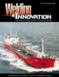
A publication of the James F. Lincoln Arc Welding Foundation
A publication of the James F. Lincoln Arc Welding Foundation
A publication of the James F. Lincoln Arc Welding Foundation

Create successful ePaper yourself
Turn your PDF publications into a flip-book with our unique Google optimized e-Paper software.
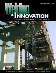
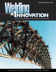
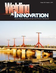
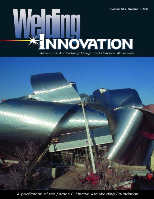
Volume XIX, Number 1, 2002<br />
A <strong>publication</strong> <strong>of</strong> <strong>the</strong> <strong>James</strong> F. <strong>Lincoln</strong> <strong>Arc</strong> <strong>Welding</strong> <strong>Foundation</strong>
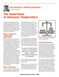
Continuing <strong>the</strong> Tradition…<br />
It was with humility that I recently accepted<br />
Duane Miller’s <strong>of</strong>fer to assist in <strong>the</strong> editing <strong>of</strong><br />
<strong>Welding</strong> Innovation. This was true because I did<br />
not think it would be possible for me to fill <strong>the</strong><br />
position left vacant by my predecessor Scott<br />
Funderburk. He covered <strong>Welding</strong> Innovation<br />
for several years as assistant editor, and he<br />
mentored well under Duane’s watchful eye. I<br />
would expect that Scott will be sorely missed<br />
here in <strong>the</strong> application engineering department<br />
and by our readership. We all wish him <strong>the</strong> very<br />
best in his new assignment.<br />
As is certainly <strong>the</strong> case with <strong>the</strong> roles <strong>of</strong> most<br />
pr<strong>of</strong>essionals employed in industry today, we are<br />
required to wear many hats, and my primary<br />
position as senior application engineer has<br />
dovetailed nicely with my additional responsibility<br />
to <strong>Welding</strong> Innovation. The irony <strong>of</strong> this is that<br />
nearly twenty years ago, I was asked to assist<br />
<strong>the</strong> former editor, Richard Sabo, by suggesting a<br />
name for this <strong>publication</strong>. We finally settled on<br />
The <strong>Welding</strong> Innovation Quarterly, and that<br />
name became synonymous with high-quality,<br />
creative design engineering concepts coupled<br />
with fundamentally strong welding principles. If<br />
you needed answers to tough problems, <strong>the</strong>n in<br />
return we were prepared as a group to provide<br />
high quality information. In principle, it is our<br />
objective to continue <strong>the</strong> rich tradition <strong>of</strong><br />
<strong>Welding</strong> Innovation, and I would like to suggest<br />
that <strong>the</strong> articles in this issue <strong>of</strong> <strong>the</strong> magazine<br />
reflect our commitment to that objective.<br />
Pr<strong>of</strong>essor Henry Petroski’s contribution to this<br />
issue, “The Fall <strong>of</strong> Skyscrapers,” provides an<br />
analysis <strong>of</strong> <strong>the</strong> collapse <strong>of</strong> <strong>the</strong> World Trade<br />
Center towers resulting from <strong>the</strong> September 11<br />
terrorist attack. In addition, Pr<strong>of</strong>essor Petroski<br />
provides us with ideas regarding future design<br />
considerations, and <strong>the</strong> practicality <strong>of</strong> future<br />
skyscraper construction. In contrast, contributing<br />
writer Carla Rautenberg provides an article that<br />
presents Frank Gehry’s free-form design <strong>of</strong> <strong>the</strong><br />
Peter B. Lewis Building at <strong>the</strong> Wea<strong>the</strong>rhead<br />
School <strong>of</strong> Management located on <strong>the</strong> Case<br />
Western Reserve University campus. The compelling<br />
design <strong>of</strong> <strong>the</strong> newly constructed Gehry<br />
design is a clear break from <strong>the</strong> historical<br />
constraints <strong>of</strong> rectangular designed structures.<br />
We are confident that this issue <strong>of</strong> <strong>Welding</strong><br />
Innovation will be thought-provoking, and we<br />
encourage your innovative input for future issues.<br />
I especially urge you to consider sharing with our<br />
readers <strong>the</strong> value <strong>of</strong> your own experience, in <strong>the</strong><br />
form <strong>of</strong> a submission to <strong>the</strong> “Lessons Learned in<br />
<strong>the</strong> Field” column initiated by our senior design<br />
consultant, Omer W. Blodgett. See page 18 for<br />
ano<strong>the</strong>r <strong>of</strong> Omer’s timeless and valuable engineering<br />
lessons.<br />
Jeff Nadzam<br />
Assistant Editor<br />
Australia and New Zealand<br />
Raymond K. Ryan<br />
Phone: 61-2-4862-3839<br />
Fax: 61-2-4862-3840<br />
INTERNATIONAL SECRETARIES<br />
Croatia<br />
Pr<strong>of</strong>. Dr. Slobodan Kralj<br />
Phone: 385-1-61-68-222<br />
Fax: 385-1-61-56-940<br />
Russia<br />
Dr. Vladimir P. Yatsenko<br />
Phone: 077-095-737-62-83<br />
Fax: 077-093-737-62-87
Cover: With a shimmering stainless steel<br />
skin concealing its intricate welded structure,<br />
<strong>the</strong> ro<strong>of</strong> <strong>of</strong> <strong>the</strong> almost-completed Peter B.<br />
Lewis Building at Case Western Reserve<br />
University definitely makes an architectural<br />
statement. See story on page 20.<br />
Omer W. Blodgett, Sc.D., P.E.<br />
Design Consultant<br />
Volume XIX<br />
Number 1, 2002<br />
Editor<br />
Duane K. Miller,<br />
Sc.D., P.E.<br />
Assistant Editor<br />
Jeff R. Nadzam<br />
The <strong>James</strong> F. <strong>Lincoln</strong><br />
<strong>Arc</strong> <strong>Welding</strong> <strong>Foundation</strong><br />
The views and opinions<br />
expressed in <strong>Welding</strong><br />
Innovation do not necessarily<br />
represent those <strong>of</strong><br />
The <strong>James</strong> F. <strong>Lincoln</strong> <strong>Arc</strong><br />
<strong>Welding</strong> <strong>Foundation</strong> or The<br />
<strong>Lincoln</strong> Electric Company.<br />
The serviceability <strong>of</strong> a<br />
product or structure utilizing<br />
<strong>the</strong> type <strong>of</strong> information<br />
presented herein is, and<br />
must be, <strong>the</strong> sole responsibility<br />
<strong>of</strong> <strong>the</strong> builder/user.<br />
Many variables beyond <strong>the</strong><br />
control <strong>of</strong> The <strong>James</strong> F.<br />
<strong>Lincoln</strong> <strong>Arc</strong> <strong>Welding</strong><br />
<strong>Foundation</strong> or The <strong>Lincoln</strong><br />
Electric Company affect <strong>the</strong><br />
results obtained in applying<br />
this type <strong>of</strong> information.<br />
These variables include,<br />
but are not limited to, welding<br />
procedure, plate chemistry<br />
and temperature,<br />
weldment design, fabrication<br />
methods, and service<br />
requirements.<br />
Features<br />
2 Orthotropic Design Meets Cold Wea<strong>the</strong>r Challenges<br />
This overview <strong>of</strong> orthotropic steel deck bridges discusses a number<br />
<strong>of</strong> examples that have been built in Norway, Russia, Sweden and Ukraine.<br />
12 The Fall <strong>of</strong> Skyscrapers<br />
In an article reprinted from American Scientist, Duke University Pr<strong>of</strong>essor<br />
Henry Petroski considers some ramifications <strong>of</strong> <strong>the</strong> collapse <strong>of</strong> <strong>the</strong> World Trade<br />
Center towers on <strong>the</strong> future skylines <strong>of</strong> <strong>the</strong> world’s cities.<br />
20 Gleaming “Waterfall” Refreshes Urban Campus<br />
The work <strong>of</strong> architect Frank Gehry inspires controversy and excitement<br />
as <strong>the</strong> new home <strong>of</strong> Case Western Reserve University’s Wea<strong>the</strong>rhead School<br />
nears completion in Cleveland, Ohio.<br />
Departments<br />
7 Design File: Designing Fillet Welds for Skewed T-Joints, Part 1<br />
11 Opportunities: <strong>Lincoln</strong> Electric Technical Programs<br />
17 Opportunities: <strong>Lincoln</strong> Electric Pr<strong>of</strong>essional Programs<br />
18 Lessons Learned in <strong>the</strong> Field: Consider <strong>the</strong> Transfer <strong>of</strong> Stress<br />
through Members<br />
Visit us online at www.<strong>Welding</strong>Innovation.com<br />
THE JAMES F. LINCOLN ARC WELDING FOUNDATION<br />
Dr. Donald N. Zwiep, Chairman<br />
Orange City, Iowa<br />
John Twyble, Trustee<br />
Mosman, NSW, Australia<br />
Duane K. Miller, Sc.D., P.E.<br />
Executive Director & Trustee<br />
Roy L. Morrow<br />
President<br />
<strong>Welding</strong> Innovation Vol. XIX, No. 1, 2002<br />
1
Orthotropic Design Meets Cold Wea<strong>the</strong>r Challenges<br />
An Overview <strong>of</strong> Orthotropic Steel Deck Bridges in Cold Regions<br />
By Alfred R. Mangus, P.E.<br />
Transportation Engineer, Civil<br />
California Dept. <strong>of</strong> Transportation (CALTRANS)<br />
Sacramento, California<br />
Introduction<br />
Initially developed by German engineers<br />
following World War II, orthotropic<br />
bridge design was a creative response<br />
to material shortages during <strong>the</strong> postwar<br />
period. Lightweight orthotropic steel<br />
bridge decks not only <strong>of</strong>fered excellent<br />
structural characteristics, but were also<br />
economical to build (Troitsky 1987).<br />
Moreover, <strong>the</strong>y could be built in cold<br />
climates at any time <strong>of</strong> <strong>the</strong> year.<br />
Engineers from around <strong>the</strong> world utilize<br />
this practical and economic system for<br />
all types <strong>of</strong> bridges. While concrete<br />
must be at or above 5 degrees Celsius<br />
to properly cure, it is physically possible<br />
to encapsulate and heat <strong>the</strong> concrete<br />
construction process; admittedly, this<br />
adds to construction costs (Mangus<br />
1988), (Mangus 1991).<br />
Orthotropic steel deck bridges have<br />
proven to be durable in cold regions.<br />
The orthotropic steel deck integrates<br />
<strong>the</strong> driving surface as part <strong>of</strong> <strong>the</strong><br />
superstructure, and has <strong>the</strong> lowest<br />
total mass <strong>of</strong> any practicable system.<br />
In Europe, where <strong>the</strong> advantages <strong>of</strong><br />
orthotropic design have been<br />
embraced with enthusiasm, <strong>the</strong>re are<br />
more than 1,000 orthotropic steel deck<br />
bridges. In all <strong>of</strong> North America, <strong>the</strong>re<br />
are fewer than 100 bridges <strong>of</strong><br />
orthotropic design.<br />
This article will give an overview <strong>of</strong><br />
imaginative steel deck bridges currently<br />
in operation in Norway, Russia,<br />
Sweden, and Ukraine. The examples<br />
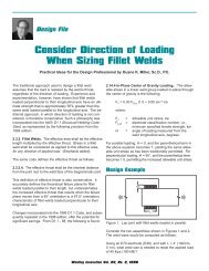
Figure 1. Rib designs.<br />
cover a matrix <strong>of</strong> rib types, superstructure<br />
types and various bridge types.<br />
Russia has developed a mass manufactured<br />
panelized orthotropic deck<br />
system and has devised special<br />
launching methods for cold regions.<br />
Russian engineers prefer <strong>the</strong> open rib<br />
design and have industrialized this<br />
system, while most o<strong>the</strong>r engineers<br />
prefer <strong>the</strong> closed rib. Researchers, as<br />
well as <strong>the</strong> owners <strong>of</strong> orthotropic steel<br />
deck bridges, continue to monitor <strong>the</strong><br />
performance <strong>of</strong> various rib types<br />
(Figure 1).<br />
In Norway<br />
Nordhordland Floating Bridge<br />
The Nordhordland Bridge across <strong>the</strong><br />
Salhus fjord is Norway’s second floating<br />
bridge and <strong>the</strong> world’s largest floating<br />
bridge (Meaas, Lande, and Vindoy,<br />
1994). The bridge was opened for traffic<br />
in 1994. The total bridge length is<br />
1615 m and consists <strong>of</strong> a high level<br />
369 m long cable stayed bridge and a<br />
1246 m long floating bridge (Figure 2).<br />
The floating bridge consists <strong>of</strong> a steel<br />
box girder, which is supported on ten<br />
concrete pontoons and connected to<br />
abutments with transition elements in<br />
forged steel. The main elements are a<br />
high-level cable stayed bridge providing<br />
a ship channel and a floating<br />
bridge between <strong>the</strong> underwater rock<br />
Klauvaskallen and <strong>the</strong> o<strong>the</strong>r side <strong>of</strong><br />
<strong>the</strong> fjord. The cable stayed bridge provides<br />
a clear ship channel. A 350 m<br />
long ramp is required to transition from<br />
<strong>the</strong> higher bridge deck on <strong>the</strong> cable<br />
2 <strong>Welding</strong> Innovation Vol. XIX, No. 1, 2002<br />
Figure 2. Nordhordland Floating Bridge across Salhus fjord <strong>of</strong> Norway.
stayed bridge to <strong>the</strong> bridge deck 11 m<br />
above <strong>the</strong> waterline. The steel box<br />
girder <strong>of</strong> <strong>the</strong> floating bridge forms a<br />
circular arch with a radius <strong>of</strong> 1,700 m<br />
in <strong>the</strong> horizontal plane. The supporting<br />
pontoons are positioned with a center<br />
distance <strong>of</strong> 113 m and act as elastic<br />
supports for <strong>the</strong> girder, which is<br />
designed without internal hinges. The<br />
bridge follows <strong>the</strong> tidal variations by<br />
elastic deformations <strong>of</strong> <strong>the</strong> girder.<br />
The steel box girder is <strong>the</strong> main loadcarrying<br />
element <strong>of</strong> <strong>the</strong> bridge (Figure<br />
3). The octagon girder is 5.5 m high<br />
and 13 m wide. The free height below<br />
<strong>the</strong> girder down to <strong>the</strong> waterline is 5.5<br />
m and this allows for passage <strong>of</strong> small<br />
boats. The plate thickness varies from<br />
14 mm to 20 mm. The plate stiffeners<br />
are in <strong>the</strong> traditional trapezoidal shape<br />
and <strong>the</strong>y span in <strong>the</strong> longitudinal direction<br />
<strong>of</strong> <strong>the</strong> girder. The stiffeners are<br />
supported by cross-frames with center<br />
distance <strong>of</strong> maximum 4.5 m. At <strong>the</strong><br />
supports on <strong>the</strong> pontoons, bulkheads<br />
are used instead <strong>of</strong> cross-frames. This<br />
is done because <strong>the</strong> loads in <strong>the</strong>se<br />
sections are significantly larger than in<br />
<strong>the</strong> cross-frames. The plate thickness<br />
Figure 3. Nordhordland Floating<br />
Bridge.<br />
in <strong>the</strong> bulkheads varies from 8 mm to<br />
50 mm. The box girder is constructed<br />
in straight elements with lengths varying<br />
from 35 m to 42 m. The elements<br />
are welded toge<strong>the</strong>r with a skew angle<br />
<strong>of</strong> 1.2° to 1.3° to accommodate <strong>the</strong><br />
arch curvature in <strong>the</strong> horizontal plane.<br />
The cross section dimensions <strong>of</strong> <strong>the</strong><br />
octagonal box girder are constant for<br />
<strong>the</strong> length <strong>of</strong> <strong>the</strong> bridge.<br />
The stress level varies significantly<br />
over <strong>the</strong> length <strong>of</strong> <strong>the</strong> bridge. In <strong>the</strong><br />
areas with <strong>the</strong> highest stresses, steel<br />
with a yield strength <strong>of</strong> 540 MPa is<br />
used.<br />
Orthotropic bridge design<br />
was a creative response<br />
to material shortages<br />
during <strong>the</strong> postwar period<br />
In <strong>the</strong> remainder <strong>of</strong> <strong>the</strong> bridge (in <strong>the</strong><br />
cross-frames and bulkheads) normalized<br />
steel with yield strength <strong>of</strong> 355<br />
MPa is used. The total steel weight <strong>of</strong><br />
<strong>the</strong> box girder is 12,500 tons, <strong>of</strong> which<br />
approximately 3,000 tons are high<br />
strength steel. The elevated ramp is<br />
approximately 350 m long and has a<br />
grade <strong>of</strong> 5.7 percent (Figure 4). The<br />
elevated ramp is constructed with an<br />
orthotropic plate deck 12 mm thick<br />
and has 8 mm and 10 mm thick trapezoidal<br />
ribs 800 mm deep. T-shaped<br />
crossbeams support <strong>the</strong> ribs with a<br />
maximum center distance <strong>of</strong> 4.5 m.<br />
The main 1,200 mm deep box girders<br />
are located one at each edge <strong>of</strong> <strong>the</strong><br />
ramp in order to maximize <strong>the</strong> stiffness<br />
about a vertical axis. The steel weight<br />
<strong>of</strong> <strong>the</strong> ramp is 1,600 tons.<br />
Figure 4. Nordhordland Floating<br />
Bridge.<br />
Bybrua Bridge<br />
The Bybrua cable stayed bridge has a<br />
main span <strong>of</strong> 185 m. The 15.5 m wide<br />
roadway superstructure was fabricated<br />
in <strong>the</strong> shop in 9.0 m sections (Figure 5).<br />
There is a combined pedestrian plus<br />
bicycles area on each side <strong>of</strong> <strong>the</strong> three<br />
traffic lanes. The cross section <strong>of</strong> <strong>the</strong><br />
main span has a deck-plate 12 mm<br />
thick, but this increases to 16 and 20<br />
mm at <strong>the</strong> cable anchorage. The bottom<br />
plate varies between 8 mm and<br />
10 mm thickness, and <strong>the</strong> webs<br />
between 12 mm and 20 mm. At<br />
intervals <strong>of</strong> 3.0 m <strong>the</strong>re are frames<br />
supporting <strong>the</strong> longitudinal stiffening<br />
system. In <strong>the</strong> bridge deck this is<br />
made up <strong>of</strong> standard trapezoidal ribs<br />
Figure 5. Bybrua Bridge.<br />
<strong>Welding</strong> Innovation Vol. XIX, No. 1, 2002 3
from <strong>the</strong> German steel company<br />
Krupp, and in <strong>the</strong> bottom flange box<br />
section <strong>of</strong> bulb flats open ribs were utilized<br />
(Aune and Holand 1981). In <strong>the</strong><br />
longitudinal direction <strong>the</strong> deck was<br />
divided into six fabricated sections,<br />
two <strong>of</strong> which were welded to <strong>the</strong> web<br />
sections. The box bottom was fabricated<br />
as three sections. The total steel<br />
weight is about 1,100 tons. All elements<br />
prefabricated in <strong>the</strong> shop were<br />
welded, as were <strong>the</strong> field splices in <strong>the</strong><br />
deck, whereas “Huck” high tensile<br />
bolts were used in all o<strong>the</strong>r field joints.<br />
All field joints were calculated as friction<br />
connections. The whole steel<br />
structure is metallized with zinc and<br />
painted according to <strong>the</strong> specifications<br />
<strong>of</strong> <strong>the</strong> Norwegian Public Roads<br />
Administration. The superstructure<br />
received <strong>the</strong> maximum live load<br />
stresses during <strong>the</strong> erection <strong>of</strong> <strong>the</strong><br />
bridge. The wearing surface <strong>of</strong> <strong>the</strong><br />
bridge deck is <strong>the</strong> same as that developed<br />
by <strong>the</strong> Danish State Road<br />
Laboratories for <strong>the</strong> Lillebelt Bridge <strong>of</strong><br />
Denmark.<br />
Storda and Bomla Bridges<br />
The “Triangle Link” project connects<br />
three islands <strong>of</strong>f <strong>the</strong> Norwegian coast<br />
south <strong>of</strong> Belgen to <strong>the</strong> mainland with<br />
three bridges (Larson and Valen<br />
Researchers continue<br />
to monitor <strong>the</strong> performance<br />
<strong>of</strong> various rib types<br />
2000). The entire project was completed<br />
in April 2001. The two orthotropic<br />
steel deck suspension bridges are<br />
known as <strong>the</strong> Storda Bridge and <strong>the</strong><br />
Bomla Bridge. The Storda Bridge is<br />
1,076 m long, has a main span <strong>of</strong> 677<br />
m, with towers 97 m high and a vertical<br />
clearance <strong>of</strong> 18 m (Figure 6). The<br />
Bomla Bridge is 990 m long with a<br />
main span <strong>of</strong> 577 m and <strong>the</strong> tower<br />
height is 105 m. The roadway <strong>of</strong> both<br />
bridges is 9.7 m wide. Scanbridge AS<br />
<strong>of</strong> Norway fabricated <strong>the</strong> Bomla<br />
Bridge’s steel approach superstructure,<br />
which was launched out over <strong>the</strong><br />
tops <strong>of</strong> <strong>the</strong> columns from <strong>the</strong> shore.<br />
The steel components for <strong>the</strong> main<br />
span superstructure <strong>of</strong> <strong>the</strong> Storda<br />
Bridge were prefabricated in <strong>the</strong><br />
Ne<strong>the</strong>rlands (Figure 6) and <strong>the</strong> main<br />
span superstructure <strong>of</strong> <strong>the</strong> Bomla<br />
Bridge was prefabricated in Italy. The<br />
orthotropic ribs for <strong>the</strong> Storda Bridge<br />
were prefabricated in France. The<br />
orthotropic sections were transported<br />
to <strong>the</strong> site by barge, and were lifted<br />
into position by a crane.<br />
Figure 6. Storda Bridge.<br />
In Russia<br />
Russian engineers have standardized<br />
<strong>the</strong>ir orthotropic deck plates using<br />
open or flat plate ribs as shown in<br />
Figure 1. They have several launching<br />
solutions or standardized methods for<br />
pushing <strong>the</strong> superstructure across a<br />
river or gorge. There are a limited<br />
number <strong>of</strong> bridge case histories documented<br />
in English, but <strong>the</strong>y provide an<br />
overall view <strong>of</strong> Russian techniques<br />
(Blank, Popov, and Seliverstov 1999).<br />
In <strong>the</strong> city <strong>of</strong> Arkhangel, Russia, a vertical<br />
lift record span bridge <strong>of</strong> 120.45<br />
m was completed in 1990 (Stepanov<br />
1991). The Berezhkovsky twin parallel<br />
bridges are multi-cell box girder<br />
bridges consisting <strong>of</strong> three spans <strong>of</strong><br />
110 m + 144.5 m +110 m. Each bridge<br />
has four traffic lanes 3.75 m wide.<br />
These bridges were <strong>the</strong> first to be<br />
launched with inclined webs<br />
(Surovtsev, Pimenov, Seliverstov, and<br />
Iourkine 2000).<br />
Oka Bridge<br />
The four-lane orthotropic twin box<br />
girder bridge crossing <strong>the</strong> Oka River<br />
on <strong>the</strong> bypass freeway around <strong>the</strong> city<br />
<strong>of</strong> Gorki, Russia, was opened to traffic<br />
in 1991 (Figure 7). The 966 m long<br />
superstructure consists <strong>of</strong> 2 spans x<br />
84 m + 5 spans x 126 m + 2 spans x<br />
84 m (Design Institute Giprotransmost<br />
1991). This bridge is a single continuous<br />
superstructure with a fixed bearing<br />
420 m away from one <strong>of</strong> <strong>the</strong> abutments.<br />
The total bridge width (29.5 m<br />
including steel traffic barriers) provides<br />
two sidewalks 1.5 m wide each, four<br />
traffic lanes, four safety shoulders and<br />
a center median. The total weight <strong>of</strong><br />
steel for <strong>the</strong> superstructure is 10,635<br />
tons, or 373 kg/m2. The orthotropic<br />
steel superstructure comprises five<br />
basic elements (Figure 7). There are<br />
two main box girders assembled from<br />
two L-shaped sections for <strong>the</strong> bottom<br />
face and sides. The intermediate<br />
orthotropic plate sections were used<br />
for <strong>the</strong> top flange <strong>of</strong> <strong>the</strong> two box girders,<br />
as well as <strong>the</strong> majority <strong>of</strong> <strong>the</strong><br />
deck. The end sections <strong>of</strong> <strong>the</strong><br />
orthotropic plate were panelized with<br />
tapered ends, because only sidewalk<br />
loading is required. The transverse<br />
diaphragms are steel trusses between<br />
<strong>the</strong> box girders. The diaphragms<br />
required extra steel beams at <strong>the</strong> bottom<br />
flange <strong>of</strong> <strong>the</strong> box girder above <strong>the</strong><br />
bearings. The main box girder was<br />
shop fabricated in L-shaped sections<br />
that are 21 m long and 3.6 m deep.<br />
The intermediate orthotropic welded<br />
steel deck plate was shop fabricated in<br />
panelized sections 2.5 m wide and<br />
11.5 m long.<br />
The longitudinal ribs <strong>of</strong> <strong>the</strong> orthotropic<br />
deck and steel box girders are flat rib<br />
plates spaced at 0.35 m, and <strong>the</strong><br />
spacing <strong>of</strong> transverse ribs is 3.0 m for<br />
both components. The stiffening ribs <strong>of</strong><br />
<strong>the</strong> main girder are located on both<br />
sides <strong>of</strong> every web. The vertical split-T<br />
ribs <strong>of</strong> <strong>the</strong> box girders were aligned<br />
with <strong>the</strong> transverse ribs <strong>of</strong> <strong>the</strong> ribbed<br />
plate, thus creating <strong>the</strong> integral internal<br />
diaphragms. The longitudinal stiffening<br />
ribs are at a constant spacing<br />
4 <strong>Welding</strong> Innovation Vol. XIX, No. 1, 2002
Figure 7. Twin box girder bridge crossing <strong>the</strong> Oka River, Russia (split–section).<br />
along <strong>the</strong> bridge. Depending on <strong>the</strong><br />
web thickness, additional vertical stiffening<br />
ribs were required between <strong>the</strong><br />
diaphragms. The superstructure was<br />
erected using “continuous launching”<br />
from one bank <strong>of</strong> <strong>the</strong> Oka River. The<br />
shop-fabricated elements were added<br />
piece by piece to form a continuous<br />
structure at <strong>the</strong> “erection slip” area on<br />
this riverbank. The joints <strong>of</strong> <strong>the</strong> horizontal<br />
sections <strong>of</strong> <strong>the</strong> orthotropic deck<br />
and ribbed plates, as well as <strong>the</strong> joints<br />
<strong>of</strong> <strong>the</strong> web <strong>of</strong> <strong>the</strong> main girder, were<br />
automatically welded. The joints <strong>of</strong> <strong>the</strong><br />
longitudinal ribs <strong>of</strong> <strong>the</strong> ribbed plate<br />
were manually welded. All <strong>the</strong> remaining<br />
joints used high strength bolts.<br />
In Sweden<br />
High Coast Suspension Bridge<br />
The High Coast Suspension Bridge <strong>of</strong><br />
Sweden is almost <strong>the</strong> same size as<br />
San Francisco’s Golden Gate Bridge<br />
(Merging with Nature 1998). The main<br />
span is 1,210 m long with suspended<br />
abutment to abutment where expansion<br />
joints and hydraulic buffers are<br />
located. The 48 box girder sections<br />
were fabricated at a shipyard in<br />
Finland (Pedersen 1997). The standard<br />
section is 20 m long with two<br />
Figure 9. High Coast, Sweden<br />
components.<br />
sets <strong>of</strong> hangers each and weighs 320<br />
tons (Figure 9). The 20 m long panels<br />
for <strong>the</strong> deck, sides and bottom were<br />
fabricated with a maximum width <strong>of</strong> 10<br />
m. They were fabricated from steel<br />
plates, typically 9 to 14 mm thick,10 m<br />
long and 3 to 3.3 m wide. The ribs<br />
were 20 m long trapezoidal ribs with a<br />
plate thickness <strong>of</strong> 6 to 8 mm.<br />
The plates were placed on a plane<br />
and welded in <strong>the</strong> transverse and longitudinal<br />
direction and <strong>the</strong> trough stiffeners<br />
were fitted and welded<br />
longitudinally. Plates connecting <strong>the</strong><br />
panels and <strong>the</strong> diaphragms were welded<br />
between ribs. The 20 m long edge<br />
sections and units for <strong>the</strong> transverse<br />
diaphragm, or bulkhead, were prefabricated.<br />
The bottom and inclined sides<br />
were placed first. Each 4 m deep<br />
transverse diaphragm or bulkhead was<br />
fitted. The edge sections were installed<br />
and finally <strong>the</strong> two deck panels were<br />
placed on top, completing a 20 m long<br />
subsection. The 31 bridge girder sections<br />
for <strong>the</strong> main span were transported<br />
from <strong>the</strong> fabrication yard in Finland<br />
on <strong>the</strong> three barges in <strong>the</strong> same way<br />
as <strong>the</strong> sections for <strong>the</strong> side spans, and<br />
erected with a floating sheerleg crane,<br />
130 m boom, starting from mid-span<br />
and proceeding towards <strong>the</strong> towers<br />
(Edwards and Westergren 1999).<br />
In Ukraine<br />
South Bridge over <strong>the</strong> Dnipro River<br />
The 1992 signature span <strong>of</strong> <strong>the</strong> South<br />
Bridge over <strong>the</strong> Dnipro [Dnepr] River<br />
in Kyiv [Kiev], Ukraine is an unsymmetrical<br />
cable stayed bridge with a<br />
main span <strong>of</strong> 271 m (Korniyiv and.<br />
Fuks 1994). The main span side <strong>of</strong> <strong>the</strong><br />
H-tower is a continuous three-span<br />
steel box girder with orthotropic steel<br />
deck. The back-span superstructure on<br />
<strong>the</strong> opposite side <strong>of</strong> <strong>the</strong> H-tower is a<br />
segmental prestressed concrete box<br />
section. Concrete construction for <strong>the</strong><br />
shorter back span <strong>of</strong> 60 m was used<br />
as a counter-weight mass equal to <strong>the</strong><br />
longer orthotropic main span. The<br />
bridge carries a six-lane roadway, two<br />
rail tracks and four large-diameter<br />
water pipes (Figure 10). The total live<br />
Figure 8. High Coast, Sweden, section.<br />
side spans <strong>of</strong> 310 m and 280 m. The<br />
width <strong>of</strong> <strong>the</strong> roadway is 17.8 m, allowing<br />
for a possible future extension to 4<br />
lanes (Figure 8). The distance<br />
between <strong>the</strong> main cables is 20.8 m<br />
and <strong>the</strong>re are 20 m between <strong>the</strong> hangers.<br />
The girder is continuous through<br />
<strong>the</strong> towers extending 1,800 m from<br />
Figure 10. South Bridge (cable stayed) <strong>of</strong> Ukraine (split–section).<br />
<strong>Welding</strong> Innovation Vol. XIX, No. 1, 2002 5
load is about 246 kN/m. The threespan<br />
(80.5 m + 90 m + 271 m) continuous<br />
steel box girders are made <strong>of</strong><br />
low-alloy steel with a minimum yield<br />
strength <strong>of</strong> 390 MPa.<br />
The bridge was divided into segments<br />
that were shop-welded. Field splices<br />
were ei<strong>the</strong>r welded or joined by highstrength<br />
bolts. Bolting was used where<br />
automatic welding was impractical<br />
because <strong>of</strong> <strong>the</strong> short length <strong>of</strong> <strong>the</strong><br />
weld or difficult access. The cross section<br />
<strong>of</strong> <strong>the</strong> twin two-cell box girder<br />
bridge consists <strong>of</strong> six vertical webs,<br />
<strong>the</strong> upper deck plate and <strong>the</strong> lower<br />
box flanges. The narrow cell is for <strong>the</strong><br />
cable stayed bridge anchorage. In <strong>the</strong><br />
central portion <strong>of</strong> <strong>the</strong> cross section<br />
that carries <strong>the</strong> two hot water supply<br />
pipes, <strong>the</strong> lower flange was omitted to<br />
preclude <strong>the</strong> undesirable effects <strong>of</strong><br />
unequal heating inside a closed box.<br />
The bearings at <strong>the</strong> piers permit lateral<br />
displacement <strong>of</strong> <strong>the</strong> superstructure<br />
because <strong>of</strong> <strong>the</strong> 41.5 m bridge width.<br />
The orthotropic decks, bottom flanges<br />
<strong>of</strong> <strong>the</strong> boxes and <strong>the</strong> webs have open<br />
flat-bar stiffening ribs, a common feature<br />
in Ukrainian and Russian bridges.<br />
Longitudinal flat or open ribs were<br />
placed on <strong>the</strong> top face <strong>of</strong> <strong>the</strong><br />
orthotropic deck plate under <strong>the</strong> rail<br />
tracks, thus avoiding intersections <strong>of</strong><br />
longitudinal and transverse stiffeners.<br />
This facilitated fabrication, at <strong>the</strong> same<br />
time precluding stress concentrations<br />
at crossing welds that would be susceptible<br />
to fatigue under dynamic train<br />
loading. Longitudinal ribs under <strong>the</strong><br />
train tracks have a depth in excess <strong>of</strong><br />
<strong>the</strong> design requirements, which permitted<br />
longitudinal pr<strong>of</strong>ile adjustments<br />
<strong>of</strong> <strong>the</strong> tracks after erection <strong>of</strong> <strong>the</strong><br />
bridge superstructure. The steel girders<br />
were pre-assembled on <strong>the</strong> bank<br />
<strong>of</strong> <strong>the</strong> south and erected by launching.<br />
The twin two-cell box girders were<br />
equipped with a launching nose and<br />
stiffened with a temporary strut system<br />
(Rosignoli1999). Single erection rollers<br />
were used at <strong>the</strong> tops <strong>of</strong> supports and<br />
had a friction factor <strong>of</strong> less than 0.015.<br />
The erection <strong>of</strong> <strong>the</strong> 271 m main span<br />
was accomplished with two false work<br />
supports providing three equal spans<br />
<strong>of</strong> about 90 m. At <strong>the</strong> H-tower <strong>of</strong> <strong>the</strong><br />
cable stayed bridge, hinged conditions<br />
are provided by supports with limited<br />
rotational capability in <strong>the</strong> vertical and<br />
<strong>the</strong> horizontal planes. The torsional<br />
rigidity <strong>of</strong> <strong>the</strong> bridge is supplied by <strong>the</strong><br />
two planes <strong>of</strong> cable stays, plus <strong>the</strong><br />
stiffness <strong>of</strong> <strong>the</strong> closed box sections.<br />
Under one-sided loading <strong>of</strong> <strong>the</strong> bridge<br />
(three traffic lanes), <strong>the</strong> deck cross<br />
slope <strong>of</strong> 0.3% was measured in field<br />
tests, less than <strong>the</strong> calculated value <strong>of</strong><br />
0.35%. Eccentric hinged connections<br />
between <strong>the</strong> bottom flanges <strong>of</strong> <strong>the</strong><br />
stiffening girders and <strong>the</strong> H-tower were<br />
constructed, considerably reducing <strong>the</strong><br />
bending moments in <strong>the</strong> girders.<br />
Conclusion<br />
The foregoing examples illustrate a<br />
range <strong>of</strong> creative responses to <strong>the</strong><br />
challenge <strong>of</strong> designing and constructing<br />
orthotropic steel deck bridges in<br />
cold wea<strong>the</strong>r regions. The versatility,<br />
economy and structural integrity <strong>of</strong><br />
welded orthotropic design undoubtedly<br />
will continue to inspire bridge designers<br />
and structural engineers in <strong>the</strong><br />
21st century.<br />
Figure Credits<br />
Figure 1 from Ballio, G., Mazzolani, F. M. 1983,<br />
“Theory and Design <strong>of</strong> Steel Design Structures,”<br />
Chapman & Hall Ltd. courtesy <strong>of</strong> Dr. Mazzolani;<br />
Figures 2, 3, & 4 courtesy <strong>of</strong> Dr. Ing. A-<br />
Aas–Jakobsen, AS Structural Engineering<br />
Consultants, Oslo, Norway; Figure 5 adapted from<br />
Aune, Petter, and Holand, Ivar (1981); Figure 6<br />
courtesy <strong>of</strong> Mr. L. Adelaide <strong>of</strong> Pr<strong>of</strong>ilafroid, France;<br />
Figures 8 & 9 courtesy <strong>of</strong> Claus Pedersen <strong>of</strong><br />
Mondberg & Thorsen AS, Copenhagen, Denmark;<br />
Figures 7 & 10 courtesy <strong>of</strong> IABSE International<br />
Association <strong>of</strong> Bridge Structural Engineers.<br />
References<br />
Aune, P., Holand, I. (1981) Norwegian Bridge<br />
Building – A Volume Honoring Arne Selberg,<br />
Tapir, Norway<br />
Blank, S. A., Popov, O. A., Seliverstov, V. A., (1999)<br />
“Chapter 66 Design Practice in Russia,” Bridge<br />
Engineering Handbook, 1st ed., Chen, W.F.,<br />
and Duan, L. Editors, CRC Press, Boca Raton<br />
Florida<br />
Design Institute Giprotransmost, (1991) “The<br />
Bridge-Crossing over <strong>the</strong> River Oka on<br />
<strong>the</strong> Bypass Road near Gorki” Structural<br />
Engineering International, IABSE, Zurich,<br />
Switzerland, Vol. 1, Number 1, 14-15<br />
Edwards,Y. & Westergren P., (1999), “Polymer<br />
modified waterpro<strong>of</strong>ing and pavement system<br />
for <strong>the</strong> High Coast Sweden” NordicRoad &<br />
Transport Research No. 2, 28<br />
Korniyiv, M. H. and Fuks, G. B (1994) “The South<br />
Bridge, Kyiv, Ukraine” Structural Engineering<br />
International, IABSE, Zurich, Switzerland, Vol.<br />
4, Number 4, 223-225<br />
Larsen J., and Valen, A., (2000) “Comparison <strong>of</strong><br />
Aerial Spinning versus Locked-Coil Cables<br />
for Two Suspension Bridges (Norway),”<br />
Structural Engineering International, IABSE,<br />
10(3), 128-131<br />
Mangus, A., (1988) “Air Structure Protection <strong>of</strong><br />
Cold Wea<strong>the</strong>r Concrete,” Concrete<br />
International, American Concrete Institute,<br />
Detroit, MI, October 22-27<br />
Mangus, A., (1991) “Construction Activities Inside<br />
<strong>of</strong> Air Structures Protected From <strong>the</strong> <strong>Arc</strong>tic<br />
Environment,” International <strong>Arc</strong>tic Technology<br />
Conference, Society <strong>of</strong> Petroleum Engineers,<br />
Anchorage, AK, May 29-31<br />
Mangus, A, and Shawn, S., (1999) “Chapter 14<br />
Orthotropic Deck Bridges,” Bridge Engineering<br />
Handbook, 1st ed., Chen, W.F., and Duan, L.<br />
Editors, CRC Press, Boca Raton Florida<br />
Mangus, A., (2000) “Existing Movable Bridges<br />
Utilizing Orthotropic Bridge Decks,” 8th Heavy<br />
Movable Bridge Symposium Lake Buena Vista<br />
Florida, Heavy Movable Structures, P. O. Box<br />
398, Middletown, NJ<br />
Merging with Nature – Hoga Kusten [High Coast]<br />
(1998), Bridge Design & Engineering, 10, (1),<br />
50–56<br />
Meaas, P., Lande, E., Vindoy, V., (1994) “Design <strong>of</strong><br />
<strong>the</strong> Salhus Floating Bridge (Nordhordland<br />
Norway),” Strait Crossings 94, Balkema,<br />
Rotterdam ISBN 90-5410 388-4 3(3), 729-734<br />
Pedersen, C., (1997) The Hoga Kusten (High<br />
Coast) Bridge-suspension bridge with 1210 m<br />
main span –construction <strong>of</strong> <strong>the</strong> superstructure,<br />
Mondberg & Thorsen A/S Copenhagen,<br />
Denmark<br />
Rosignoli, M.,(1999) Launched Bridges –<br />
Prestressed Concrete Bridges built on <strong>the</strong><br />
ground and launched into <strong>the</strong>ir final position,<br />
ASCE Press, Reston, VA<br />
Stepanov, G. M., (1991), “Design <strong>of</strong> Movable<br />
Bridges,” Structural Engineering International,<br />
IABSE, Zurich, Switzerland, Volume 1,<br />
Number 1, 9-1<br />
Surovtsev, V., Pimenov, S., Seliverstov, V., &<br />
Iourkine, S, (2000) “Development <strong>of</strong> Structural<br />
Forms and Analysis <strong>of</strong> Steel Box Girders with<br />
inclined webs for operation and erection conditions”<br />
Giprotransmost J.S.Co, Pavla<br />
Kortchagina str. 2, 129278 Moscow, Russian<br />
Federation<br />
Troitsky, M. S., (1987) Orthotropic Bridges - Theory<br />
and Design, 2nd ed., The <strong>James</strong> F. <strong>Lincoln</strong> <strong>Arc</strong><br />
<strong>Welding</strong> <strong>Foundation</strong>, Cleveland, OH<br />
6 <strong>Welding</strong> Innovation Vol. XIX, No. 1, 2002
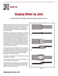
Design File<br />
Designing Fillet Welds for Skewed T-joints—Part 1<br />
Practical Ideas for <strong>the</strong> Design Pr<strong>of</strong>essional by Duane K. Miller, Sc.D., P.E.<br />
Introduction<br />
Detailing fillet welds for 90-degree T-joints is a fairly<br />
straightforward activity. Take <strong>the</strong> 90-degree T-joint and skew<br />
it—that is, rotate <strong>the</strong> upright member so as to create an<br />
acute and obtuse orientation, and <strong>the</strong> resultant geometry<br />
<strong>of</strong> <strong>the</strong> fillet welds becomes more complicated (see Figure<br />
1). The greater <strong>the</strong> degree <strong>of</strong> rotation, <strong>the</strong> greater <strong>the</strong> difference<br />
as compared to <strong>the</strong> 90-degree counterpart.<br />
A series <strong>of</strong> equations can be used to determine weld sizes<br />
for various angular orientations and required throat dimensions.<br />
Since <strong>the</strong> weld sizes on ei<strong>the</strong>r side <strong>of</strong> <strong>the</strong> joint are<br />
not necessarily required to be <strong>of</strong> <strong>the</strong> same size, <strong>the</strong>re are a<br />
variety <strong>of</strong> combinations that can be used to transfer <strong>the</strong><br />
loads across <strong>the</strong> joint. While <strong>the</strong>re are <strong>the</strong>oretical savings<br />
to be seen by optimizing <strong>the</strong> combinations <strong>of</strong> weld sizes,<br />
rarely do such efforts result in a change in fillet weld size <strong>of</strong><br />
even one standard size.<br />
Codes prescribe different methods <strong>of</strong> indicating <strong>the</strong><br />
required weld size. These are summarized herein.<br />
When acute angles become smaller, <strong>the</strong> difficulty <strong>of</strong><br />
achieving a quality weld in <strong>the</strong> root increases. The AWS<br />
D1.1 Structural <strong>Welding</strong> Code deals with this issue by<br />
requiring <strong>the</strong> consideration <strong>of</strong> a Z-loss factor.<br />
This edition <strong>of</strong> Design File addresses <strong>the</strong> situation where<br />
<strong>the</strong> end <strong>of</strong> <strong>the</strong> upright member in <strong>the</strong> skewed T-joint is parallel<br />
to <strong>the</strong> surface <strong>of</strong> <strong>the</strong> o<strong>the</strong>r member. A future Design<br />
File column will consider <strong>the</strong> situation in which <strong>the</strong> upright<br />
member has a square cut on <strong>the</strong> end, resulting in a gap on<br />
<strong>the</strong> obtuse side. Also to be addressed in <strong>the</strong> future are<br />
weld options o<strong>the</strong>r than fillet welds in skewed T-joints.<br />
LEG<br />
SIZE<br />
DIHEDRAL ANGLE<br />
0<br />
135 MAX<br />
ω 2<br />
ω 1<br />
ψ 2<br />
ω ψ 1<br />
1<br />
f 2<br />
ω 2<br />
b 2 b 1<br />
f 1<br />
t 2<br />
t 1<br />
b 2<br />
b 1<br />
Figure 1. Equal throat sizes (t 1 = t 2 ).<br />
DIHEDRAL<br />
ANGLE<br />
0<br />
60 MIN<br />
The Geometry<br />
Figure 1 provides a visual representation <strong>of</strong> <strong>the</strong> issue. For<br />
<strong>the</strong> 90-degree orientation, <strong>the</strong> weld throat is 70.7% <strong>of</strong> <strong>the</strong><br />
weld leg dimension. This relationship does not hold true for<br />
fillet welds in skewed joints. On <strong>the</strong> obtuse side, <strong>the</strong> weld<br />
throat is smaller than what would be expected for a fillet<br />
weld <strong>of</strong> a similar leg size in a 90-degree joint, and <strong>the</strong><br />
opposite is <strong>the</strong> case for <strong>the</strong> acute side. These factors must<br />
be considered when <strong>the</strong> fillet weld leg size is determined<br />
and specified.<br />
Careful examination <strong>of</strong> <strong>the</strong> fillet welds on <strong>the</strong> skewed joint<br />
raises this question: What is <strong>the</strong> size <strong>of</strong> <strong>the</strong> fillet weld in a<br />
skewed joint?<br />
LEG<br />
SIZE<br />
Figure 1 illustrates <strong>the</strong> fillet weld leg size for a skewed T-<br />
joint, and is designated by “ω.” This, however, is inconsistent<br />
with AWS Terms and Definitions (AWS A3.0-94) which<br />
defines a “fillet weld leg” as “The distance from <strong>the</strong> joint<br />
root to <strong>the</strong> toe <strong>of</strong> <strong>the</strong> fillet weld.” According to this definition,<br />
and as shown in Figure 1, <strong>the</strong> fillet weld leg is dimension<br />
“b.” The dimension that is labeled “ω” is <strong>the</strong> distance from a<br />
member to a parallel line extended from <strong>the</strong> bottom weld<br />
<strong>Welding</strong> Innovation Vol. XIX, No. 1, 2002 7
toe. While not technically correct according to AWS A3.0, it<br />
is <strong>the</strong> dimension and terminology used when fillet welds in<br />
skewed joints are discussed in <strong>the</strong> AWS D1.1 Structural<br />
<strong>Welding</strong> Code, as well as o<strong>the</strong>r AWS <strong>publication</strong>s (i.e., The<br />
<strong>Welding</strong> Handbook, ninth edition, volume 1). Such terminology<br />
will be used here.<br />
This raises an additional question: What would a weld<br />
inspector actually measure when dealing with a fillet weld<br />
in a skewed T-joint? Conventional fillet weld gauges could<br />
be used to measure <strong>the</strong> obtuse side’s fillet weld leg dimension<br />
“ω” as shown in Figure 1. Dimension “b” would be difficult<br />
to measure directly since <strong>the</strong> location <strong>of</strong> <strong>the</strong> weld root<br />
cannot be easily determined. Welds on <strong>the</strong> acute side are<br />
impossible to measure using conventional fillet weld<br />
gauges. The face dimension “f,” however, <strong>of</strong>fers an easy<br />
alternative: when this dimension is known for <strong>the</strong> weld size<br />
and <strong>the</strong> dihedral angle, <strong>the</strong> welder and inspector can easily<br />
determine what <strong>the</strong> actual size is by using a pair <strong>of</strong><br />
dividers. Alternately, a series <strong>of</strong> simple gauges <strong>of</strong> various<br />
widths could be made to directly compare <strong>the</strong> requirements<br />
to <strong>the</strong> actual weld size. Thus, dimension “f” may be important<br />
for controlling weld sizes in skewed T-joints.<br />
When sizing a fillet weld for 90-degree T-joints or skewed T-<br />
joints, <strong>the</strong> starting point is to determine <strong>the</strong> required throat<br />
size needed to resist <strong>the</strong> applied loads. From <strong>the</strong> throat<br />
dimension, <strong>the</strong> fillet weld leg size can be determined. Three<br />
options will be considered:<br />
Where <strong>the</strong> throat size is <strong>the</strong> same on ei<strong>the</strong>r side <strong>of</strong> <strong>the</strong><br />
joint (see Figure 1)<br />
To determine <strong>the</strong> required fillet weld size for a given throat,<br />
<strong>the</strong> following relationship can be used:<br />
ψ<br />
ω = 2 t sin<br />
(<br />
2<br />
) (1)<br />
The width <strong>of</strong> <strong>the</strong> face <strong>of</strong> <strong>the</strong> weld (“f”) can be found from<br />
this equation:<br />
(2)<br />
f = 2 t tan (<br />
ψ<br />
2 )<br />
Dimension “b,” that is, <strong>the</strong> ‘true’ fillet leg size, can be found<br />
from this relationship: t<br />
b =<br />
cos (<br />
ψ<br />
2 )<br />
(3)<br />
Finally, <strong>the</strong> cross-sectional area <strong>of</strong> <strong>the</strong> weld metal can be<br />
determined from <strong>the</strong> following:<br />
A = t 2 tan (<br />
ψ<br />
2 )<br />
(4)<br />
Where <strong>the</strong> leg size is <strong>the</strong> same on both sides<br />
(see Figure 2)<br />
If <strong>the</strong> designer decides to make both welds with <strong>the</strong> same<br />
leg size (as is illustrated in figure 2), <strong>the</strong> first required step<br />
is to determine <strong>the</strong> composite total dimension <strong>of</strong> <strong>the</strong> two<br />
8 <strong>Welding</strong> Innovation Vol. XIX, No. 1, 2002<br />
ω 2<br />
b<br />
ω 1<br />
b<br />
b<br />
t 2<br />
Figure 2. Equal fillet weld leg sizes (ω 1 = ω 2 ).<br />
throat sizes. This dimension “t T ” is <strong>the</strong>n inserted into <strong>the</strong> following<br />
equations to determine <strong>the</strong> two throats “t 1 ” and “t 2 .”<br />
ψ<br />
cos<br />
t 1<br />
= t T<br />
(<br />
1<br />
2 )<br />
ψ<br />
cos (<br />
1<br />
)<br />
ψ<br />
+ cos (<br />
2<br />
)<br />
2<br />
ψ<br />
cos<br />
t 2<br />
= t T<br />
(<br />
2<br />
2 )<br />
ψ<br />
cos (<br />
1<br />
)<br />
ψ<br />
+ cos (<br />
2<br />
)<br />
2<br />
Equations 1 – 4 can be used to find <strong>the</strong> corresponding fillet<br />
weld leg size, face dimension, “b” dimension, and crosssectional<br />
area. These calculations will be made using <strong>the</strong><br />
applicable throat dimension “t” determined from equations<br />
5 and 6, not <strong>the</strong> total throat dimension “t T ” used in equations<br />
5 and 6.<br />
Where a minimum quantity <strong>of</strong> weld metal is used<br />
(see Figure 3)<br />
Even a casual review <strong>of</strong> Figure 1 shows that, when fillet<br />
weld leg sizes are specified to be <strong>of</strong> <strong>the</strong> same size on<br />
ei<strong>the</strong>r side <strong>of</strong> <strong>the</strong> skewed T-joint, <strong>the</strong> use <strong>of</strong> weld metal is<br />
as efficient as could be. Minimum weld metal can be<br />
obtained by taking advantage <strong>of</strong> <strong>the</strong> more favorable condition<br />
that results on <strong>the</strong> acute side where a greater weld<br />
throat can be obtained for <strong>the</strong> same quantity <strong>of</strong> metal that<br />
would be placed on <strong>the</strong> obtuse side.<br />
To minimize <strong>the</strong> volume <strong>of</strong> weld metal used in <strong>the</strong> combination<br />
<strong>of</strong> <strong>the</strong> two welds, <strong>the</strong> following equations may be used<br />
once <strong>the</strong> total throat dimension “t T ” is known:<br />
t 1<br />
=<br />
t 2<br />
=<br />
1 + tan 2 (<br />
1 + tan 2 (<br />
t T<br />
ψ1<br />
)<br />
t T<br />
2<br />
ψ2<br />
)<br />
2<br />
t 1<br />
b<br />
2<br />
2<br />
(5)<br />
(6)<br />
(7)<br />
(8)
Although <strong>the</strong> preceding calculations are not particularly difficult,<br />
Table 1 has been provided to simplify <strong>the</strong> process.<br />
Columns A and B are used to determine fillet weld leg<br />
sizes and face widths for various dihedral angles. To obtain<br />
<strong>the</strong> required fillet weld size, <strong>the</strong> calculated throat is multiplied<br />
by <strong>the</strong> factor in Column A. Face widths can be found<br />
following <strong>the</strong> same procedure.<br />
t 2<br />
b 2<br />
b 1<br />
t 1<br />
If <strong>the</strong> same leg size is desired on ei<strong>the</strong>r side <strong>of</strong> <strong>the</strong> joint,<br />
columns C-E are used. In this case <strong>the</strong> total weld throat “t T ”<br />
is used, as opposed to what was done with columns<br />
A and B.<br />
For <strong>the</strong> minimum weld volume, columns F–H can be used.<br />
Again, <strong>the</strong> total weld throat “t T ” is used.<br />
As will be discussed below, for dihedral angles <strong>of</strong> 30–60<br />
degrees, <strong>the</strong> D1.1 Code requries <strong>the</strong> application <strong>of</strong> a Z-loss<br />
factor. Thus, <strong>the</strong> values in Table 1 that apply to dihedral angles<br />
where this applies are shown in blue numbers to remind <strong>the</strong><br />
user to incorporate this factor into <strong>the</strong> weld throat sizes.<br />
b 2<br />
b 1<br />
Figure 3. Minimum weld volume.<br />
Influence <strong>of</strong> Dihedral Angle<br />
AWS D1.1 Structural <strong>Welding</strong> Code–Steel provides for five<br />
groupings <strong>of</strong> skewed T-joints, depending on <strong>the</strong> range <strong>of</strong><br />
sizes <strong>of</strong> <strong>the</strong> dihedral angle: a) Obtuse angles greater than<br />
100 degrees, b) angles <strong>of</strong> 80–100 degrees, c) acute angles<br />
<strong>of</strong> 60–80 degrees, d) acute angles <strong>of</strong> 30–60 degrees, and<br />
e) acute angles <strong>of</strong> less than 30 degrees. Each is dealt with<br />
in a slightly different manner.<br />
Dihedral Angle<br />
Leg & Face Dimensions<br />
Multipy by t<br />
Table 1.<br />
Same Leg Size<br />
Multipy by t T<br />
Minimum Weld Volume<br />
Multipy by t T<br />
Ψ A B C D E F G H<br />
phi1 deg leg size face width throat leg size face width throat leg size face width<br />
30 0.517 0.536 0.788 0.408 0.422 0.933 0.483 0.536<br />
35 0.601 0.630 0.760 0.457 0.479 0.910 0.547 0.630<br />
40 0.684 0.728 0.733 0.501 0.533 0.883 0.604 0.728<br />
45 0.765 0.828 0.707 0.541 0.585 0.854 0.653 0.828<br />
50 0.845 0.932 0.682 0.576 0.635 0.822 0.694 0.932<br />
55 0.923 1.04 0.657 0.607 0.684 0.787 0.726 1.04<br />
60 1.00 1.15 0.634 0.634 0.731 0.750 0.750 1.15<br />
65 1.07 1.27 0.611 0.656 0.778 0.712 0.764 1.27<br />
70 1.15 1.40 0.588 0.674 0.823 0.671 0.770 1.40<br />
75 1.22 1.53 0.566 0.689 0.868 0.630 0.766 1.53<br />
80 1.29 1.68 0.544 0.699 0.912 0.587 0.755 1.68<br />
85 1.35 1.83 0.522 0.705 0.956 0.544 0.735 1.83<br />
90 1.41 2.00 0.500 0.707 0.999 0.500 0.707 2.00<br />
95 1.47 2.18 0.478 0.705 1.043 0.457 0.673 2.18<br />
100 1.53 2.38 0.456 0.699 1.087 0.414 0.633 2.38<br />
105 1.59 2.60 0.434 0.689 1.131 0.371 0.589 2.60<br />
110 1.64 2.85 0.412 0.675 1.175 0.329 0.540 2.85<br />
115 1.69 3.14 0.389 0.656 1.221 0.289 0.488 3.14<br />
120 1.73 3.46 0.366 0.634 1.267 0.250 0.434 3.46<br />
125 1.77 3.84 0.343 0.608 1.314 0.214 0.379 3.84<br />
130 1.81 4.28 0.318 0.577 1.363 0.179 0.324 4.28<br />
135 1.85 4.82 0.293 0.542 1.413 0.147 0.271 4.82<br />
140 1.88 5.48 0.267 0.502 1.465 0.117 0.221 5.48<br />
145 1.91 6.33 0.240 0.458 1.519 0.091 0.173 6.33<br />
150 1.93 7.44 0.212 0.409 1.576 0.067 0.130 7.44<br />
Blue numbers indicate that Z-loss factors must be considered.<br />
<strong>Welding</strong> Innovation Vol. XIX, No. 1, 2002 9
Obtuse angles greater than 100 degrees<br />
For this category, contract drawings should show <strong>the</strong><br />
required effective throat. Shop drawings are to show <strong>the</strong><br />
required leg dimension, calculated with equation 1, or by<br />
using columns C or D <strong>of</strong> Table 1 (AWS D1.1-2002, para<br />
2.2.5.2, 2.3.3.2).<br />
Angles <strong>of</strong> 80–100 degrees<br />
For this group, shop drawings are required to show <strong>the</strong><br />
fillet leg size (AWS D1.1-2002, para 2.2.5.2). While not<br />
specifically stated in <strong>the</strong> code, <strong>the</strong> assumption is that<br />
contract drawings also show this dimension.<br />
Angles <strong>of</strong> 60–80 degrees<br />
For this category, contract drawings should show <strong>the</strong><br />
required effective throat. Shop drawings are to show <strong>the</strong><br />
required leg dimension (AWS D1.1-2002, para 2.2.5.2,<br />
2.3.3.2)<br />
Angles <strong>of</strong> 30–60 degrees<br />
Contract drawings are to show <strong>the</strong> effective throat. Shop<br />
drawings are required to “show <strong>the</strong> required leg dimensions<br />
to satisfy <strong>the</strong> required effective throat, increased by <strong>the</strong> Z-<br />
loss allowance ... ” (AWS D1.1-2002, para 2.2.5.2, 2.3.3.3).<br />
The Z-loss factor is used to account for <strong>the</strong> likely incidence<br />
<strong>of</strong> poor quality welding in <strong>the</strong> root <strong>of</strong> a joint with a small<br />
included angle. The amount <strong>of</strong> poor quality weld in <strong>the</strong> root<br />
<strong>of</strong> <strong>the</strong> joint is a function <strong>of</strong> <strong>the</strong> dihedral angle, <strong>the</strong> welding<br />
process, and <strong>the</strong> position <strong>of</strong> welding. Table 2.2 <strong>of</strong> D1.1<br />
summarizes this data as contained below:<br />
Table 2. Z-loss dimension.<br />
60 o >Ψ > 45 o FCAW-S 1/8 3 FCAW-S 0 0<br />
FCAW-G 1/8 3 FCAW-G 0 0<br />
Position <strong>of</strong> <strong>Welding</strong> Position <strong>of</strong> <strong>Welding</strong><br />
V or OH<br />
H or F<br />
Dihedral Angle Ψ Process Z (in.) Z (mm) Process Z (in.) Z (mm)<br />
SMAW 1/8 3 SMAW 1/8 3<br />
GMAW N/A N/A GMAW 0 0<br />
45 o >Ψ > 30 o<br />
SMAW 1/4 6 SMAW 1/4 6<br />
FCAW-S 1/4 6 FCAW-S 1/8 3<br />
FCAW-G 3/8 10 FCAW-G 1/4 6<br />
GMAW N/A N/A GMAW 1/4 6<br />
Once <strong>the</strong> Z-loss dimension has been determined, it is added<br />
to <strong>the</strong> required throat dimension. Even though part <strong>of</strong> <strong>the</strong><br />
weld in <strong>the</strong> root is considered to be <strong>of</strong> such poor quality as<br />
to be incapable <strong>of</strong> transferring stress, <strong>the</strong> resultant weld will<br />
contain sufficient quality weld metal to permit <strong>the</strong> transfer <strong>of</strong><br />
imposed loads. Figure 4 illustrates this concept.<br />
The data in Table 1 that applies to dihedral angles <strong>of</strong><br />
30–60 degrees has been shown in blue numbers because<br />
<strong>the</strong>se values must be modified to account for <strong>the</strong> Z-loss<br />
factors. Such a modification has not been done for <strong>the</strong> data<br />
in <strong>the</strong> Table.<br />
Z<br />
Figure 4. Z-loss.<br />
Acute angles less than 30 degrees<br />
The D1.1 code says that welds in joints with dihedral<br />
angles <strong>of</strong> less than 30 degrees “shall not be considered as<br />
effective in transmitting applied forces …” and <strong>the</strong>n goes<br />
on to discuss a single exception related to tubular structures.<br />
In that exception, with qualification <strong>of</strong> <strong>the</strong> welding<br />
procedure specification, such welds may be used for transferring<br />
applied stresses. For plate (e.g., non-tubular) applications,<br />
such an option is not presented in <strong>the</strong> code.<br />
The practical application <strong>of</strong> this principle is that when welds<br />
are placed on <strong>the</strong> acute side, no capacity is assigned to<br />
<strong>the</strong> weld. Ra<strong>the</strong>r, <strong>the</strong> full load is assumed to be transferred<br />
with <strong>the</strong> weld on <strong>the</strong> obtuse side.<br />
Practical Considerations<br />
The most straightforward, and easiest, approach to determining<br />
<strong>the</strong> required weld size is to assume two welds with<br />
equal throat dimensions will be used, calculate <strong>the</strong><br />
required weld throat dimension, and <strong>the</strong>n calculate <strong>the</strong><br />
required fillet weld leg size, using ei<strong>the</strong>r equation 1 or Table<br />
1, columns A and B. Simple? Yes. Best? Let’s see.<br />
The optimizing method that uses equations 6 and 7 will<br />
result in reduced weld metal volumes. But, reduced how<br />
much? The significance increases with greater rotations<br />
from <strong>the</strong> 90-degree T-joint orientation. For angles <strong>of</strong> 80, 70,<br />
and 60 degrees, <strong>the</strong> differences in weld volume are<br />
approximately 3, 12 and 25%. However, note that <strong>the</strong>se differences<br />
are functions <strong>of</strong> <strong>the</strong> leg size squared. Accordingly,<br />
<strong>the</strong> change in leg size is approximately 1, 6, and 13%. In<br />
practical terms, for dihedral angles between 60 and 120<br />
degrees, <strong>the</strong>re will not be a standard fillet weld leg size<br />
until <strong>the</strong> welds become quite large. In <strong>the</strong> case <strong>of</strong> a 70-<br />
degree dihedral angle, for example, and assuming a 1/8 in.<br />
increment for standard sizing <strong>of</strong> fillet welds over 1 in. leg<br />
size, <strong>the</strong> leg size would need to be 2 in. before <strong>the</strong> optimized<br />
weld size would result in a smaller weld. For a 2 mm<br />
standard size, this would equal a 34 mm fillet.<br />
t<br />
ω<br />
ω<br />
ψ 1<br />
10 <strong>Welding</strong> Innovation Vol. XIX, No. 1, 2002
For angles less than 60 degrees, <strong>the</strong>re can be significant<br />
differences in weld volume. These are situations where <strong>the</strong><br />
Z-loss factor must be considered as well. Thus, for angles<br />
<strong>of</strong> 30–60 degrees, optimization <strong>of</strong> weld size makes sense,<br />
and <strong>the</strong> Z-loss factors can be considered at <strong>the</strong> same time.<br />
It must be recognized that o<strong>the</strong>r code provisions may fur<strong>the</strong>r<br />
affect <strong>the</strong>se results. For example, when optimized for<br />
minimum weld volume, welds on <strong>the</strong> obtuse side may be<br />
smaller than minimum fillet weld sizes as contained in Table<br />
5.8 <strong>of</strong> D1.1. The calculated sizes, if less than <strong>the</strong>se minimums,<br />
must be increased to comply with this requirement.<br />
There does not appear to be any intrinsic value in having<br />
welds on opposite sides <strong>of</strong> <strong>the</strong> skewed T-joint be <strong>of</strong> <strong>the</strong><br />
same size. If this approach is used, <strong>the</strong> resultant weld volumes<br />
will fall somewhere between <strong>the</strong> results for <strong>the</strong> same<br />
sized throat and <strong>the</strong> optimized sizes.<br />
After <strong>the</strong> welds are detailed, <strong>the</strong> joint must be welded.<br />
Practical considerations apply here too. It must be recognized<br />
that <strong>the</strong> ratio <strong>of</strong> <strong>the</strong> face width “f” to <strong>the</strong> throat dimension<br />
“t” constitutes <strong>the</strong> equivalent <strong>of</strong> a width-to-depth ratio<br />
for <strong>the</strong> root pass. On <strong>the</strong> obtuse side, this ratio is large,<br />
exceeding 1:6 for dihedral angle <strong>of</strong> 106 degrees or more. It<br />
is very difficult to get a single weld bead to “wash” out this<br />
wide without electrode manipulation (weaving). On <strong>the</strong><br />
acute side, <strong>the</strong> ratio is less than 1:2 for angles <strong>of</strong> 62<br />
degrees. This can lead to width-to-depth ratio cracking.<br />
Recommendations<br />
When determining fillet weld details for skewed T-joints with<br />
dihedral angles from 60–120 degrees, it rarely matters<br />
which method <strong>of</strong> proportioning <strong>of</strong> weld sizes is used. Using<br />
equal throat dimensions is a straightforward method, similar<br />
to what is typically done for fillet welds on ei<strong>the</strong>r side <strong>of</strong> a<br />
90-degree T-joint. Unless <strong>the</strong> weld size is large, optimizing it<br />
will probably not result in a smaller specified weld size.<br />
For fillet welds on skewed T-joints with dihedral angles from<br />
30–60 degrees, <strong>the</strong> Z-loss factor must be considered.<br />
Based on <strong>the</strong> specific dihedral angle, <strong>the</strong> welding process,<br />
and <strong>the</strong> position <strong>of</strong> welding, <strong>the</strong> Z-loss factor can be determined,<br />
and this dimension added to <strong>the</strong> required weld<br />
throat dimension.<br />
It is important to consider how <strong>the</strong>se dimensions should be<br />
communicated between <strong>the</strong> designer, fabricator, welder and<br />
inspector. The face dimension is a practical means <strong>of</strong> verifying<br />
that <strong>the</strong> proper weld size has been achieved.<br />
Opportunities<br />
<strong>Lincoln</strong> Electric Technical Programs<br />
<strong>Welding</strong> Technology Workshop<br />
June 10-14, 2002<br />
July 29 – August 2, 2002<br />
The purpose <strong>of</strong> this program is to<br />
introduce or enhance knowledge <strong>of</strong><br />
current thinking in arc welding safety,<br />
<strong>the</strong>ory, processes, and practices. The<br />
course is designed primarily for welding<br />
instructors, supervisors and pr<strong>of</strong>essional<br />
welders. Fee: $395.<br />
<strong>Welding</strong> <strong>of</strong> Aluminum Alloys,<br />
Theory and Practice<br />
October 15-18, 2002<br />
Designed for engineers, technologists,<br />
technicians and welders who are<br />
already familiar with basic welding<br />
processes, this technical training<br />
program provides equal amounts <strong>of</strong><br />
classroom time and hands-on welding.<br />
Fee: $595.<br />
Space is limited, so register early to avoid disappointment. For full details, see<br />
www.lincolnelectric.com/knowledge/training/seminars/<br />
Or call 216/383-2240, or write to Registrar, Pr<strong>of</strong>essional Programs, The <strong>Lincoln</strong> Electric<br />
Company, 22801 St. Clair Avenue, Cleveland, OH 44117-1199.<br />
<strong>Welding</strong> Innovation Vol. XIX, No. 1, 2002 11
The Fall <strong>of</strong> Skyscrapers<br />
By Henry Petroski<br />
A.S. Vesic Pr<strong>of</strong>essor <strong>of</strong> Civil Engineering<br />
and Pr<strong>of</strong>essor <strong>of</strong> History<br />
Duke University<br />
Durham, North Carolina<br />
Editor’s Note: This article first<br />
appeared in American Scientist,<br />
Volume 90, January-February 2002.<br />
It is reprinted here with permission.<br />
Copyright, Henry Petroski, 2002.<br />
The article is reprinted as written earlier<br />
this year. In <strong>the</strong> ensuing months,<br />
many investigations have been performed,<br />
and <strong>the</strong> level <strong>of</strong> understanding<br />
<strong>of</strong> some <strong>of</strong> <strong>the</strong> technical aspects <strong>of</strong><br />
<strong>the</strong> World Trade Center collapse have<br />
increased. The results <strong>of</strong> <strong>the</strong> FEMA<br />
investigation discussed in this article<br />
are now available at www.house.gov/<br />
science/hot/wtc/wtcreport.htm<br />
The terrorist attacks <strong>of</strong> September 11,<br />
2001, did more than bring down <strong>the</strong><br />
World Trade Center towers. The collapse<br />
<strong>of</strong> those New York City megastructures,<br />
once <strong>the</strong> fifth and sixth<br />
tallest buildings in <strong>the</strong> world, signaled<br />
<strong>the</strong> beginning <strong>of</strong> a new era in <strong>the</strong> planning,<br />
design, construction and use <strong>of</strong><br />
skyscrapers . For <strong>the</strong> foreseeable<br />
future, at least in <strong>the</strong> West, <strong>the</strong>re are<br />
not likely to be any new super-tall<br />
buildings proposed, and only those<br />
currently under construction will be<br />
added to <strong>the</strong> skylines <strong>of</strong> <strong>the</strong> great<br />
cities <strong>of</strong> <strong>the</strong> world. Even <strong>the</strong> continued<br />
occupancy <strong>of</strong> signature skyscrapers<br />
may come under scrutiny by <strong>the</strong>ir<br />
prime tenants.<br />
Since two hijacked airplanes loaded<br />
with jet fuel were crashed within about<br />
15 minutes <strong>of</strong> each o<strong>the</strong>r into <strong>the</strong> two<br />
most prominent and symbolic structures<br />
<strong>of</strong> lower Manhattan, <strong>the</strong> once<br />
reassuringly low numbers generated<br />
by probabilistic risk assessment seem<br />
irrelevant. What happened in New York<br />
ceased being a hypo<strong>the</strong>tical, incredible<br />
or ignorable scenario. From now on,<br />
12 <strong>Welding</strong> Innovation Vol. XIX, No. 1, 2002<br />
Figure 1. With <strong>the</strong> collapse <strong>of</strong> <strong>the</strong> World Trade Center towers, <strong>the</strong> fate <strong>of</strong> future<br />
skyscraper projects has come into question.<br />
structural engineers must be prepared<br />
to answer harder questions about how<br />
skyscrapers will stand up to <strong>the</strong> impact<br />
<strong>of</strong> jumbo jets and, perhaps more<br />
important, how <strong>the</strong>y will fare in <strong>the</strong><br />
ensuing conflagration. <strong>Arc</strong>hitects will<br />
likely have to respond more to questions<br />
about stairwells and evacuation<br />
routes than to those about facades<br />
and spires. Because <strong>of</strong> <strong>the</strong> nature <strong>of</strong><br />
skyscrapers, nei<strong>the</strong>r engineers nor<br />
architects will be able to find answers<br />
that will satisfy everyone.<br />
Inclination, Not Economy<br />
Although <strong>the</strong> idea <strong>of</strong> <strong>the</strong> skyscraper is<br />
modern, <strong>the</strong> inclination to build upward<br />
is not. The Great Pyramids, with <strong>the</strong>ir<br />
broad bases, reached heights unapproached<br />
for <strong>the</strong> next four millennia.<br />
But even <strong>the</strong> great Gothic ca<strong>the</strong>drals,<br />
crafted <strong>of</strong> bulky stone into an aes<strong>the</strong>tic<br />
<strong>of</strong> lightness and slenderness, are<br />
dwarfed by <strong>the</strong> steel and reinforced<br />
concrete structures <strong>of</strong> <strong>the</strong> 20th century.<br />
It was modern building materials<br />
that made <strong>the</strong> true skyscraper structurally<br />
possible, but it was <strong>the</strong> mechanical<br />
device <strong>of</strong> <strong>the</strong> elevator that made<br />
<strong>the</strong> skyscraper truly practical.<br />
Ironically, it is also <strong>the</strong> elevator that<br />
has had so much to do with limiting<br />
<strong>the</strong> height <strong>of</strong> most tall buildings to<br />
about 70 or 80 stories. Above that,<br />
elevator shafts occupy more than 25<br />
percent <strong>of</strong> <strong>the</strong> volume <strong>of</strong> a tall building,<br />
and so <strong>the</strong> economics <strong>of</strong> renting out<br />
space argues against investing in<br />
greater height.<br />
The World Trade Center towers were<br />
110 stories tall, but even with an elaborate<br />
system <strong>of</strong> local and express elevators,<br />
<strong>the</strong> associated sky lobbies and<br />
utilities located in <strong>the</strong> core still<br />
removed almost 30 percent <strong>of</strong> <strong>the</strong> towers’<br />
floor area from <strong>the</strong> rentable space<br />
category. By all planning estimates,
<strong>the</strong> World Trade Center towers should<br />
have been viewed as a poor investment<br />
and so might not have been<br />
undertaken as a strictly private enterprise.<br />
In fact, it was <strong>the</strong> Port <strong>of</strong> New<br />
York Authority, <strong>the</strong> bi-state governmental<br />
entity now known as <strong>the</strong> Port<br />
Authority <strong>of</strong> New York and New Jersey,<br />
that in <strong>the</strong> 1960s undertook to build<br />
<strong>the</strong> towers. With its ability to issue<br />
bonds, <strong>the</strong> Port Authority could afford<br />
to undertake a financially risky project<br />
that few corporations would dare.<br />
Sometimes private enterprise does<br />
engage in similarly questionable<br />
investments, balancing <strong>the</strong> tangible<br />
financial risk with <strong>the</strong> intangible gain in<br />
publicity, with <strong>the</strong> hope that it will<br />
translate ultimately into pr<strong>of</strong>it. This was<br />
<strong>the</strong> case with <strong>the</strong> Empire State<br />
Building, completed in 1931 and now<br />
<strong>the</strong> seventh tallest building in <strong>the</strong><br />
world. Although it was not heavily<br />
The Port Authority could<br />
undertake a financially risky<br />
project that few corporations<br />
would dare<br />
occupied at first, <strong>the</strong> cachet <strong>of</strong> <strong>the</strong><br />
world’s tallest building made it a prestigious<br />
address and added to its realestate<br />
value. The Sears Tower stands<br />
an impressive 110 stories tall, <strong>the</strong><br />
same count that <strong>the</strong> World Trade<br />
Center towers once claimed. This skyscraper<br />
gained for its owner <strong>the</strong> prestige<br />
<strong>of</strong> having its corporate name<br />
associated with <strong>the</strong> tallest building in<br />
<strong>the</strong> world. The Sears Tower, completed<br />
in 1974, one year after <strong>the</strong> second<br />
World Trade Center tower was finished,<br />
held that title for more than 20<br />
years-until <strong>the</strong> twin Petronas Towers<br />
were completed in Kuala Lumpur,<br />
Malaysia, in 1998, emphasizing <strong>the</strong><br />
rise <strong>of</strong> <strong>the</strong> Far East as <strong>the</strong> location <strong>of</strong><br />
new megastructures.<br />
Building Innovation<br />
It is not only <strong>the</strong> innovative use <strong>of</strong> elevators,<br />
marketing and political will that<br />
has enabled super-tall buildings to be<br />
built. A great deal <strong>of</strong> <strong>the</strong> cost <strong>of</strong> such a<br />
structure is in <strong>the</strong> amount <strong>of</strong> materials<br />
it contains, so lightening <strong>the</strong> structure<br />
lowers its cost. Innovative uses <strong>of</strong><br />
building materials can also give a skyscraper<br />
more desirable <strong>of</strong>fice space.<br />
Now more than 70 years old, <strong>the</strong> steel<br />
frame <strong>of</strong> <strong>the</strong> Empire State Building has<br />
closely spaced columns, which break<br />
up <strong>the</strong> floor space and limit <strong>of</strong>fice layouts.<br />
In contrast, <strong>the</strong> World Trade<br />
Center employed a tubular-construction<br />
principle, in which closely spaced<br />
steel columns were located around <strong>the</strong><br />
periphery <strong>of</strong> <strong>the</strong> building. Sixty-footlong<br />
steel trusses spanned between<br />
<strong>the</strong>se columns and <strong>the</strong> inner structure<br />
<strong>of</strong> <strong>the</strong> towers, where fur<strong>the</strong>r columns<br />
were located, along with <strong>the</strong> elevator<br />
shafts, stairwells and o<strong>the</strong>r non-exclusive<br />
<strong>of</strong>fice space. Between <strong>the</strong> core<br />
and tube proper, <strong>the</strong> broad columnless<br />
space enabled open, imaginative<br />
and attractive <strong>of</strong>fice layouts.<br />
The tubular concept was not totally<br />
new with <strong>the</strong> World Trade Center, it<br />
having been used in <strong>the</strong> diagonally<br />
braced and tapered John Hancock<br />
Center, completed in Chicago in 1969.<br />
The Sears Tower is also a tubular<br />
structure, but it consists <strong>of</strong> nine 75-<br />
foot(23-meter)-square tubes bundled<br />
toge<strong>the</strong>r at <strong>the</strong> lower stories. The varying<br />
heights <strong>of</strong> <strong>the</strong> tubes give <strong>the</strong> Sears<br />
Tower an ever-changing look, as it presents<br />
a different pr<strong>of</strong>ile when viewed<br />
from <strong>the</strong> different directions from<br />
which one approaches it when driving<br />
<strong>the</strong> city’s expressways. When new to<br />
<strong>the</strong> Manhattan skyline, <strong>the</strong> unrelieved<br />
209-foot(64-meter)-square plans and<br />
unbroken 1,360-foot(415-meter)-high<br />
pr<strong>of</strong>iles <strong>of</strong> <strong>the</strong> twin World Trade Center<br />
buildings came in for considerable<br />
architectural criticism for <strong>the</strong>ir lack <strong>of</strong><br />
character. Like <strong>the</strong> Sears Tower, however,<br />
when viewed from different<br />
angles, <strong>the</strong> buildings, especially as<br />
<strong>the</strong>y played <strong>of</strong>f against each o<strong>the</strong>r,<br />
enjoyed a great aes<strong>the</strong>tic synergy. The<br />
view <strong>of</strong> <strong>the</strong> towers from <strong>the</strong> walkway <strong>of</strong><br />
<strong>the</strong> Brooklyn Bridge was especially<br />
striking, with <strong>the</strong> stark twin monoliths<br />
echoing <strong>the</strong> twin Gothic arches <strong>of</strong> <strong>the</strong><br />
bridge’s towers.<br />
Although <strong>the</strong> World Trade Center towers<br />
did look like little more than tall<br />
prisms from afar, <strong>the</strong> play <strong>of</strong> <strong>the</strong> everchanging<br />
sunlight on <strong>the</strong>ir aluminumclad<br />
columns made <strong>the</strong>m new<br />
buildings by <strong>the</strong> minute. From a closer<br />
perspective, <strong>the</strong> multiplicity <strong>of</strong> unbroken<br />
columns corseting each building<br />
also gave it an architectural texture.<br />
The tubular concept<br />
was not totally new<br />
with <strong>the</strong> WTC<br />
The close spacing <strong>of</strong> <strong>the</strong> columns was<br />
dictated by <strong>the</strong> desire to make <strong>the</strong><br />
structure as nearly a perfect tube as<br />
possible. A true tube, like a straw,<br />
would be unpunctured by peripheral<br />
openings, but since skyscrapers are<br />
inhabited by people, windows are considered<br />
a psychological must. At <strong>the</strong><br />
same time, too-large windows in very<br />
tall buildings can give some occupants<br />
an uneasy feeling. The compromise<br />
struck in <strong>the</strong> World Trade Center was<br />
to use tall but narrow windows<br />
between <strong>the</strong> steel columns. In fact, <strong>the</strong><br />
width <strong>of</strong> <strong>the</strong> window openings was<br />
said to be less than <strong>the</strong> width <strong>of</strong> a person’s<br />
shoulders, which was intended<br />
by <strong>the</strong> designers to provide a measure<br />
<strong>of</strong> reassurance to <strong>the</strong> occupants.<br />
Since <strong>the</strong> terrorist attack, however,<br />
one <strong>of</strong> <strong>the</strong> most haunting images <strong>of</strong><br />
those windows is <strong>of</strong> so many people<br />
standing sideways in <strong>the</strong> openings,<br />
clinging to <strong>the</strong> columns and, ultimately,<br />
falling, jumping or being carried to<br />
<strong>the</strong>ir death.<br />
<strong>Welding</strong> Innovation Vol. XIX, No. 1, 2002 13
Failure Analyses<br />
Terrorists first attempted to bring <strong>the</strong><br />
World Trade Center towers down in<br />
1993, when a truck bomb exploded in<br />
<strong>the</strong> lower-level public garage, at <strong>the</strong><br />
base <strong>of</strong> <strong>the</strong> north tower. Power was<br />
lost in <strong>the</strong> tower and smoke rose<br />
through it. It was speculated that <strong>the</strong><br />
terrorists were attempting to topple <strong>the</strong><br />
north tower into <strong>the</strong> south one, but<br />
even though several floors <strong>of</strong> <strong>the</strong><br />
garage were blown out, <strong>the</strong> structure<br />
stood. There was some concern<br />
among engineers <strong>the</strong>n that <strong>the</strong> basement<br />
columns, no longer braced by<br />
<strong>the</strong> garage floors, would buckle, and<br />
so <strong>the</strong>y were fitted with steel bracing<br />
before <strong>the</strong> recovery work proceeded.<br />
After that attack, access to <strong>the</strong> underground<br />
garage was severely restricted,<br />
and security in <strong>the</strong> towers was considerably<br />
increased. No doubt <strong>the</strong> 1993<br />
bombing was on <strong>the</strong> minds <strong>of</strong> many<br />
people when <strong>the</strong> airplanes struck <strong>the</strong><br />
towers last September.<br />
As <strong>the</strong>y had in <strong>the</strong> earlier bombing, <strong>the</strong><br />
World Trade Center towers clearly survived<br />
<strong>the</strong> impact <strong>of</strong> <strong>the</strong> Boeing 767 airliners.<br />
Given <strong>the</strong> proven robustness <strong>of</strong><br />
<strong>the</strong> structures to <strong>the</strong> earlier bombing<br />
assault, <strong>the</strong> thought that <strong>the</strong> buildings<br />
might actually collapse was probably<br />
far from <strong>the</strong> minds <strong>of</strong> many <strong>of</strong> those<br />
The survival <strong>of</strong> <strong>the</strong> WTC<br />
after <strong>the</strong> 1993 bombing<br />
seems to have given<br />
an unwarranted sense<br />
<strong>of</strong> security<br />
who were working in <strong>the</strong>m on September<br />
11. It certainly appears not to have<br />
been feared by <strong>the</strong> police and fire<br />
fighters who rushed in to save people<br />
and extinguish <strong>the</strong> fires. Indeed, <strong>the</strong><br />
survival <strong>of</strong> <strong>the</strong> World Trade Center<br />
after <strong>the</strong> 1993 bombing seems to have<br />
given an unwarranted sense <strong>of</strong> security<br />
that <strong>the</strong> buildings could withstand<br />
even <strong>the</strong> inferno created by <strong>the</strong> estimated<br />
20,000 gallons (76,000 liters) <strong>of</strong><br />
jet fuel that each plane carried. (That<br />
amount <strong>of</strong> fuel has been estimated to<br />
have an energy content equivalent to<br />
about 2.4 million sticks <strong>of</strong> dynamite.)<br />
Steel buildings are expected to be firepro<strong>of</strong>ed,<br />
and so <strong>the</strong> World Trade<br />
Center towers were. However, firepro<strong>of</strong>ing<br />
is a misnomer, for it only insulates<br />
<strong>the</strong> steel from <strong>the</strong> heat <strong>of</strong> <strong>the</strong> fire<br />
for a limited period, which is supposed<br />
to be enough time to allow for <strong>the</strong> fire<br />
to be brought under control, if not<br />
extinguished entirely. Unfortunately, jet<br />
fuel burns at a much higher temperature<br />
than would a fire fed by normal<br />
construction materials and <strong>the</strong> customary<br />
furniture and contents found in an<br />
<strong>of</strong>fice building. Fur<strong>the</strong>rmore, conventional<br />
fire-fighting means, such as<br />
water, have little effect on burning jet<br />
fuel. The World Trade Center fire, estimated<br />
to have produced temperatures<br />
as high as <strong>of</strong> <strong>the</strong> order <strong>of</strong> <strong>the</strong> melting<br />
point <strong>of</strong> steel, continued unabated. It<br />
has been speculated that some <strong>of</strong> <strong>the</strong><br />
steel beams and columns <strong>of</strong> <strong>the</strong> structure<br />
that were not destroyed by <strong>the</strong><br />
impact eventually may have been<br />
heated close to if not beyond <strong>the</strong>ir<br />
melting point, but this appears to have<br />
been unlikely.<br />
Even if it did not melt, <strong>the</strong> prolonged<br />
elevated temperatures caused <strong>the</strong><br />
steel to expand, s<strong>of</strong>ten, sag, bend and<br />
creep. The intense heat also caused<br />
<strong>the</strong> concrete floor, no longer adequately<br />
supported by <strong>the</strong> steel beams and<br />
columns in place before <strong>the</strong> impact <strong>of</strong><br />
<strong>the</strong> airplane, to crack, spall and break<br />
up, compromising <strong>the</strong> synergistic<br />
action <strong>of</strong> <strong>the</strong> parts <strong>of</strong> <strong>the</strong> structure.<br />
Without <strong>the</strong> stabilizing effect <strong>of</strong> <strong>the</strong> stiff<br />
floors, <strong>the</strong> steel columns still intact<br />
became less and less able to sustain<br />
<strong>the</strong> load <strong>of</strong> <strong>the</strong> building above <strong>the</strong>m.<br />
When <strong>the</strong> weight <strong>of</strong> <strong>the</strong> portion <strong>of</strong> <strong>the</strong><br />
building above became too much for<br />
<strong>the</strong> locally damaged and s<strong>of</strong>tened<br />
structure to withstand, it collapsed<br />
onto <strong>the</strong> floors below. The impact <strong>of</strong><br />
<strong>the</strong> falling top <strong>of</strong> <strong>the</strong> building on <strong>the</strong><br />
lower floors, whose steel columns<br />
were also s<strong>of</strong>tened by heat transfer<br />
along <strong>the</strong>m, caused <strong>the</strong>m to collapse<br />
in turn, creating an unstoppable chain<br />
reaction. The tower that was struck<br />
second failed first in part because <strong>the</strong><br />
plane hit lower, leaving a greater<br />
weight to be supported above <strong>the</strong><br />
damaged area. (The collapse <strong>of</strong> <strong>the</strong><br />
lower floors <strong>of</strong> <strong>the</strong> towers under <strong>the</strong><br />
falling weight <strong>of</strong> <strong>the</strong> upper floors<br />
occurred for <strong>the</strong> same reason that a<br />
book easily supported on a glass table<br />
can break that same table if dropped<br />
on it from a sufficient height.)<br />
Within days <strong>of</strong> <strong>the</strong> collapse <strong>of</strong> <strong>the</strong> towers,<br />
failure analyses appeared on <strong>the</strong><br />
Internet and in engineering classrooms.<br />
Perhaps <strong>the</strong> most widely circulated<br />
were <strong>the</strong> mechanics-based<br />
analysis <strong>of</strong> Zdenek Bazant <strong>of</strong><br />
Northwestern University and <strong>the</strong> energy<br />
approach <strong>of</strong> Thomas Mackin <strong>of</strong> <strong>the</strong><br />
University <strong>of</strong> Illinois at Urbana-<br />
Champaign. Each <strong>of</strong> <strong>the</strong>se estimated<br />
that <strong>the</strong> falling upper structure <strong>of</strong> a<br />
World Trade Center tower exerted on<br />
<strong>the</strong> lower structure a force some 30<br />
times what it had once supported.<br />
Charles Clifton, a New Zealand structural<br />
engineer, argues that <strong>the</strong> fire was<br />
not <strong>the</strong> principal cause <strong>of</strong> <strong>the</strong> collapse.<br />
He thinks that it was <strong>the</strong> damaged<br />
core ra<strong>the</strong>r than <strong>the</strong> exterior tube<br />
columns that succumbed first to <strong>the</strong><br />
enormous load from above. Once <strong>the</strong><br />
core support was lost on <strong>the</strong> impacted<br />
floors, <strong>the</strong>re was no stopping <strong>the</strong> progressive<br />
collapse, which was largely<br />
channeled by <strong>the</strong> structural tube to<br />
occur in a vertical direction. In <strong>the</strong><br />
wake <strong>of</strong> <strong>the</strong> World Trade Center disaster,<br />
<strong>the</strong> immediate concerns were, <strong>of</strong><br />
course, to rescue as many people as<br />
might have survived. Unfortunately,<br />
even to recover most <strong>of</strong> <strong>the</strong> bodies<br />
proved an ultimately futile effort. The<br />
twin towers were gigantic structures.<br />
Each floor <strong>of</strong> each building encompassed<br />
an acre, and <strong>the</strong> towers<br />
enclosed 60 million cubic feet each.<br />
Toge<strong>the</strong>r, <strong>the</strong>y contained 200,000 tons<br />
<strong>of</strong> steel and 425,000 cubic yards (325<br />
cubic meters) or about 25,000 tons <strong>of</strong><br />
concrete. The pile <strong>of</strong> debris in some<br />
places reached as high as a ten-story<br />
building. A month after <strong>the</strong> terrorist<br />
14 <strong>Welding</strong> Innovation Vol. XIX, No. 1, 2002
attack, it was estimated that only 15<br />
percent <strong>of</strong> <strong>the</strong> debris had been<br />
removed, and it was estimated that it<br />
would take a year to clear <strong>the</strong> site.<br />
Forensic Engineering<br />
Among <strong>the</strong> concerns engineers had<br />
about <strong>the</strong> clean-up operation was how<br />
<strong>the</strong> removal <strong>of</strong> debris might affect <strong>the</strong><br />
stability <strong>of</strong> <strong>the</strong> ground around <strong>the</strong> site.<br />
Because <strong>the</strong> land on which <strong>the</strong> World<br />
Trade Center was built had been part<br />
<strong>of</strong> <strong>the</strong> Hudson River, an innovative<br />
barrier had to be developed at <strong>the</strong><br />
time <strong>of</strong> construction to prevent river<br />
water from flowing into <strong>the</strong> basement<br />
<strong>of</strong> <strong>the</strong> structures. This was done with<br />
<strong>the</strong> construction <strong>of</strong> a slurry wall, in<br />
which <strong>the</strong> water was held back by a<br />
deep trench filled with a mudlike mixture<br />
until a hardened concrete barrier<br />
was in place. The completed structure<br />
provided a watertight enclosure, which<br />
came to be known as <strong>the</strong> “bathtub”<br />
within which <strong>the</strong> World Trade Center<br />
was built. The basement floors <strong>of</strong> <strong>the</strong><br />
twin towers acted to stabilize <strong>the</strong> bathtub,<br />
but <strong>the</strong>se were crushed when <strong>the</strong><br />
towers broke up and collapsed into <strong>the</strong><br />
enclosure. Early indications were that<br />
<strong>the</strong> bathtub remained intact, but in<br />
order to be sure its walls do not collapse<br />
when <strong>the</strong> last <strong>of</strong> <strong>the</strong> debris and<br />
thus all <strong>the</strong> internal support is<br />
removed, vulnerable sections <strong>of</strong> <strong>the</strong><br />
concrete wall were being tied back to<br />
<strong>the</strong> bedrock under <strong>the</strong> site even as <strong>the</strong><br />
debris removal was proceeding.<br />
Atop <strong>the</strong> pile <strong>of</strong> debris, <strong>the</strong> steel<br />
beams and columns were <strong>the</strong> largest<br />
and most recognizable parts in <strong>the</strong><br />
wreckage. The concrete, sheetrock<br />
and firepro<strong>of</strong>ing that were in <strong>the</strong> building<br />
were largely pulverized by <strong>the</strong> collapsing<br />
structure, as evidenced by <strong>the</strong><br />
ubiquitous dust present in <strong>the</strong> aftermath.<br />
(A significant amount <strong>of</strong><br />
asbestos was apparently used only in<br />
<strong>the</strong> lower floors <strong>of</strong> one <strong>of</strong> <strong>the</strong> towers,<br />
bad publicity about <strong>the</strong> material having<br />
accelerated during <strong>the</strong> construction <strong>of</strong><br />
<strong>the</strong> World Trade Center. Never<strong>the</strong>less,<br />
in <strong>the</strong> days after <strong>the</strong> collapse, <strong>the</strong><br />
All <strong>of</strong> <strong>the</strong> speculations<br />
about <strong>the</strong> mechanism<br />
<strong>of</strong> collapse are in fact<br />
hypo<strong>the</strong>ses<br />
once-intolerant Environmental<br />
Protection Agency declared <strong>the</strong> air<br />
safe.) The grille-like remains <strong>of</strong> <strong>the</strong><br />
buildings’ facades, towering precariously<br />
over what came to be known as<br />
Ground Zero, became a most eerie<br />
image. Though many argued for leaving<br />
<strong>the</strong>se ca<strong>the</strong>dral wall-like skeletons<br />
standing as memorials to <strong>the</strong> dead,<br />
<strong>the</strong>y posed a hazard to rescue workers<br />
and were in time torn down and<br />
carted away for possible future reuse<br />
in a reconstructed memorial. As is<br />
<strong>of</strong>ten <strong>the</strong> case following such a<br />
tragedy, <strong>the</strong>re was also some disagreement<br />
about how to treat <strong>the</strong><br />
wreckage generally. Early on, <strong>the</strong>re<br />
was clearly a need to remove as much<br />
<strong>of</strong> it from <strong>the</strong> site as quickly as possible<br />
so that what survivors <strong>the</strong>re might<br />
be could be uncovered. This necessitated<br />
cutting up steel columns into<br />
sections that could fit on large flatbed<br />
trucks. Even <strong>the</strong> disposal <strong>of</strong> <strong>the</strong> wreckage<br />
presented a problem. Much <strong>of</strong> <strong>the</strong><br />
steel was marked for immediate recycling,<br />
but forensic engineers worried<br />
that valuable clues to exactly how <strong>the</strong><br />
structures collapsed would be lost.<br />
All <strong>of</strong> <strong>the</strong> speculations <strong>of</strong> engineers<br />
about <strong>the</strong> mechanism <strong>of</strong> <strong>the</strong> collapse<br />
are in fact hypo<strong>the</strong>ses, <strong>the</strong>ories <strong>of</strong><br />
what might have happened. Although<br />
computer models will no doubt be constructed<br />
to test those hypo<strong>the</strong>ses and<br />
<strong>the</strong>ories, actual pieces <strong>of</strong> <strong>the</strong> wreckage<br />
may provide <strong>the</strong> most convincing<br />
confirmation that <strong>the</strong> collapse <strong>of</strong> <strong>the</strong><br />
structures did in fact progress as<br />
hypo<strong>the</strong>sized. Though <strong>the</strong> wreckage<br />
may appear to be hopelessly jumbled<br />
and crushed, telltale clues can survive<br />
among <strong>the</strong> debris. Pieces <strong>of</strong> partially<br />
melted steel, for example, can provide<br />
<strong>the</strong> means for establishing how hot <strong>the</strong><br />
fire burned and where <strong>the</strong> collapse<br />
might have initiated. Badly bent<br />
columns can give evidence <strong>of</strong> buckling<br />
before and during collapse. Even <strong>the</strong><br />
scratches and scars on large pieces <strong>of</strong><br />
steel can be useful in determining <strong>the</strong><br />
sequence <strong>of</strong> collapse. This will be <strong>the</strong><br />
task <strong>of</strong> teams <strong>of</strong> experts announced<br />
shortly after <strong>the</strong> tragedy by <strong>the</strong><br />
American Society <strong>of</strong> Civil Engineers<br />
and <strong>the</strong> Federal Emergency<br />
Management Agency. Also in <strong>the</strong><br />
immediate wake <strong>of</strong> <strong>the</strong> collapse, <strong>the</strong><br />
National Science <strong>Foundation</strong> awarded<br />
eight grants to engineering and social<br />
science researchers to assess <strong>the</strong><br />
debris as it is being removed and to<br />
study <strong>the</strong> behavior <strong>of</strong> emergency<br />
response and management teams.<br />
Analyzing <strong>the</strong> failure <strong>of</strong> <strong>the</strong> towers is a<br />
Herculean task, but it is important that<br />
engineers understand in detail what<br />
happened so that <strong>the</strong>y incorporate <strong>the</strong><br />
lessons learned into future design<br />
practices. It was <strong>the</strong> careful failure<br />
analysis <strong>of</strong> <strong>the</strong> bombed Federal<br />
Building in Oklahoma City that led<br />
engineers to delineate guidelines for<br />
designing more terrorist-resistant<br />
buildings. The Pentagon was actually<br />
undergoing retr<strong>of</strong>itting to make it better<br />
able to withstand an explosion when it<br />
was hit by a third hijacked plane on<br />
September 11. Part <strong>of</strong> <strong>the</strong> section <strong>of</strong><br />
<strong>the</strong> building that was struck had in fact<br />
just been streng<strong>the</strong>ned, and it suffered<br />
much less damage than <strong>the</strong> old section<br />
beside it, thus demonstrating <strong>the</strong><br />
effectiveness <strong>of</strong> <strong>the</strong> work.<br />
Understanding how <strong>the</strong> World Trade<br />
Center towers collapsed will enable<br />
engineers to build more attack-resistant<br />
skyscrapers. Even before a<br />
detailed failure analysis is completed,<br />
however, it is evident that one way to<br />
minimize <strong>the</strong> damage to tall structures<br />
is to prevent airplanes and <strong>the</strong>ir fuel<br />
from being able to penetrate deeply<br />
into <strong>the</strong> buildings in <strong>the</strong> first place.<br />
This is not an impossible task. When a<br />
B-25 bomber struck <strong>the</strong> Empire State<br />
<strong>Welding</strong> Innovation Vol. XIX, No. 1, 2002 15
Building in 1945, its body stuck out<br />
from <strong>the</strong> 78th and 79th floors like a<br />
long car in a short garage. The building<br />
suffered an 18-by-20-foot (5.5-by-<br />
6-meter) hole in its face, but <strong>the</strong>re was<br />
no conflagration, and <strong>the</strong>re certainly<br />
was no collapse. The greatest damage<br />
was done by <strong>the</strong> engines coming<br />
loose and flying like missiles through<br />
<strong>the</strong> building. The wreckage <strong>of</strong> <strong>the</strong><br />
plane was removed, <strong>the</strong> local damage<br />
repaired and <strong>the</strong> building restored to<br />
its original state. Among <strong>the</strong> differences<br />
between <strong>the</strong> Empire State<br />
Building and World Trade Center incidents<br />
was that in <strong>the</strong> former case, relatively<br />
speaking, a lighter plane struck<br />
a heavier structure. Fur<strong>the</strong>rmore, <strong>the</strong><br />
propeller-driven bomber was on a<br />
short-range flight from Bedford,<br />
Massachusetts to Newark airport and<br />
The towers might have stood<br />
after <strong>the</strong> attack if <strong>the</strong> fires had<br />
been extinguished quickly<br />
so did not have on board <strong>the</strong> amount<br />
<strong>of</strong> fuel necessary to complete a<br />
transcontinental flight or to bring down<br />
a skyscraper.<br />
Modern tall buildings can be streng<strong>the</strong>ned<br />
to be more resistant to full penetration<br />
by even <strong>the</strong> heaviest <strong>of</strong> aircraft.<br />
This can be done by placing more and<br />
heavier columns around <strong>the</strong> periphery<br />
<strong>of</strong> <strong>the</strong> structure, making <strong>the</strong> tube<br />
denser and thicker, as it were. The ultimate<br />
defense would be to make <strong>the</strong><br />
facade a solid wall <strong>of</strong> steel or concrete,<br />
or both. This would eliminate windows<br />
entirely, <strong>of</strong> course, which would defeat<br />
some <strong>of</strong> <strong>the</strong> purpose <strong>of</strong> a skyscraper,<br />
which is in part to provide a dramatic<br />
view from a prestigious <strong>of</strong>fice or board<br />
room. The elimination <strong>of</strong> that attraction,<br />
in conjunction with <strong>the</strong> increased mass<br />
<strong>of</strong> <strong>the</strong> structure itself, would provide<br />
space that would command a significantly<br />
lower rent and yet cost a great<br />
deal more to build. Indeed, no one<br />
would likely even consider building or<br />
Courtesy <strong>of</strong> American Scientist<br />
Figure 2. Structural design <strong>of</strong> <strong>the</strong><br />
World Trade Center towers was a tube<br />
with a central core.<br />
renting space in such a building.<br />
Hence, <strong>the</strong> solution would be a Pyrrhic<br />
victory over terrorists.<br />
The World Trade Center towers might<br />
have stood after <strong>the</strong> terrorist attack if<br />
<strong>the</strong> fires had been extinguished quickly.<br />
But even if <strong>the</strong> conventional sprinkler<br />
systems had not been damaged,<br />
water would not have been effective<br />
against <strong>the</strong> burning jet fuel. Perhaps<br />
skyscrapers could be fitted with a<br />
robust fire-fighting system employing<br />
<strong>the</strong> kind <strong>of</strong> foam that is laid down on<br />
airport runways during emergency<br />
landings, or fitted with some o<strong>the</strong>r oxygen-depriving<br />
scheme, if <strong>the</strong>re could<br />
also be a way for fleeing people to<br />
brea<strong>the</strong> in such an environment. Such<br />
schemes would need robustness and<br />
redundancy to survive tremendous<br />
impact forces, so any such system<br />
might be unattractively bulky and prohibitively<br />
expensive to install. O<strong>the</strong>r<br />
approaches might include more effective<br />
firepro<strong>of</strong>ing, such as employing<br />
ceramic-based materials, thus at least<br />
giving <strong>the</strong> occupants <strong>of</strong> a burning<br />
building more time to evacuate.<br />
The evacuation <strong>of</strong> tall buildings will no<br />
doubt now be given much more attention<br />
by architects and engineers alike.<br />
Each World Trade Center tower had<br />
multiple stairways, but all were in <strong>the</strong><br />
single central core <strong>of</strong> <strong>the</strong> building. In<br />
contrast, stairways in Germany, for<br />
example, are required to be in different<br />
corners <strong>of</strong> <strong>the</strong> building. In that configuration,<br />
it is much more likely that one<br />
stairway will remain open even if a<br />
plane crashes into ano<strong>the</strong>r corner. But<br />
locating stairwells in <strong>the</strong> corners <strong>of</strong> a<br />
building means, <strong>of</strong> course, that prime<br />
<strong>of</strong>fice space cannot be located <strong>the</strong>re.<br />
In o<strong>the</strong>r words, most measures to<br />
make buildings safer also make <strong>the</strong>m<br />
more expensive to build and diminish<br />
<strong>the</strong> appeal <strong>of</strong> <strong>the</strong>ir <strong>of</strong>fice space. This<br />
dilemma is at <strong>the</strong> heart <strong>of</strong> <strong>the</strong> reason<br />
why <strong>the</strong> future <strong>of</strong> <strong>the</strong> skyscraper is<br />
threatened.<br />
It is likely that, in <strong>the</strong> wake <strong>of</strong> <strong>the</strong><br />
World Trade Center collapses, any<br />
super-tall building currently in <strong>the</strong><br />
development stage will be put on hold<br />
and reconsidered. Real-estate<br />
investors will want to know how <strong>the</strong><br />
proposed building will stand up to <strong>the</strong><br />
crash <strong>of</strong> a fully fueled jumbo jet, how<br />
hot <strong>the</strong> ensuing fire will burn, how long<br />
it will take to be extinguished and how<br />
long <strong>the</strong> building will stand so that <strong>the</strong><br />
occupants can evacuate. The investors<br />
will also want to know who will rent <strong>the</strong><br />
space if it is built.<br />
Potential tenants will have <strong>the</strong> same<br />
questions about terrorist attacks.<br />
Companies will also wonder if <strong>the</strong>ir<br />
employees will be willing to work on<br />
<strong>the</strong> upper stories <strong>of</strong> a tall building.<br />
Managers will wonder if those employees<br />
who do agree to work in <strong>the</strong> building<br />
will be constantly distracted,<br />
watching out <strong>the</strong> window for approaching<br />
airplanes. Corporations will wonder<br />
if clients will be reluctant to come to a<br />
place <strong>of</strong> business perceived to be vulnerable<br />
to attack. The very need to<br />
have workers grouped toge<strong>the</strong>r on<br />
adjacent floors in tall buildings is also<br />
being called into question.<br />
After <strong>the</strong> events <strong>of</strong> September 11, <strong>the</strong><br />
incentive to build a signature structure,<br />
a distinctive super-tall building that<br />
sticks out in <strong>the</strong> skyline, is greatly<br />
diminished. In <strong>the</strong> immediate future, as<br />
leases come up for renewal in existing<br />
skyscrapers, real-estate investors will<br />
be watching closely for trends. It is<br />
unlikely that our most familiar skylines<br />
will be greatly changed in <strong>the</strong> foreseeable<br />
future. Indeed, if companies begin<br />
16 <strong>Welding</strong> Innovation Vol. XIX, No. 1, 2002
to move <strong>the</strong>ir operations wholesale out<br />
<strong>of</strong> <strong>the</strong> most distinctive and iconic <strong>of</strong><br />
super-tall buildings and into more nondescript<br />
structures <strong>of</strong> moderate height,<br />
it is not unimaginable that cities like<br />
New York and Chicago will in time see<br />
<strong>the</strong> reversal <strong>of</strong> a long-standing trend.<br />
We might expect no longer to see<br />
developers buying up land, demolishing<br />
<strong>the</strong> low-rise buildings on it, and<br />
putting up a new skyscraper. Instead,<br />
owners might be more likely to demolish<br />
a vacant skyscraper and erect in<br />
its place a building that is not significantly<br />
smaller or taller than its neighbors.<br />
Skylines that were once<br />
immediately recognizable even in silhouette<br />
for <strong>the</strong>ir peaks and valleys<br />
may someday be as flat as a mesa.<br />
There is no imperative to such an<br />
interplay between technology and<br />
society. What really happens in <strong>the</strong><br />
coming years will depend largely on<br />
how businesses, governments and<br />
individuals react to terrorism and <strong>the</strong><br />
threat <strong>of</strong> terrorism. Unfortunately, <strong>the</strong><br />
image <strong>of</strong> <strong>the</strong> World Trade Center towers<br />
collapsing will remain in our collective<br />
consciousness for a few<br />
Skylines once recognizable in<br />
silhouette may someday be as<br />
flat as a mesa<br />
generations, at least. Thus, it is no idle<br />
speculation to think that it will be at<br />
least a generation before skyscrapers<br />
return to ascendancy, if <strong>the</strong>y ever do.<br />
Developments in micro-miniaturization,<br />
telecommunications, information technology,<br />
business practice, management<br />
science, economics, psychology<br />
and politics will likely play a much larger<br />
role than architecture and engineering<br />
in determining <strong>the</strong> immediate<br />
future <strong>of</strong> macro-structures, at least in<br />
<strong>the</strong> West.<br />
Bibliography<br />
Bazant, Zdenek P., and Youg Zhou. 2001. “Why<br />
did <strong>the</strong> World Trade Center collapse?-Simple<br />
analysis.” Journal <strong>of</strong> Engineering Mechanics,<br />
vol. 128 (2002) pp 2-6. www3.tam.uiuc.edu/<br />
news/200109 c/<br />
Clifton, G. Charles. 2001. Collapse <strong>of</strong> <strong>the</strong> World<br />
Trade Center towers. www.hera.org.nz/pdf<br />
files/worldtrade centre.pdf<br />
Mackin, Thomas J. 2001. Engineering analysis<br />
<strong>of</strong> tragedy at WTC. Presentation slides for ME<br />
346, Department <strong>of</strong> Mechanical Engineering,<br />
University <strong>of</strong> Illinois at Urbana-Champaign.<br />
Opportunities<br />
<strong>Lincoln</strong> Electric Pr<strong>of</strong>essional Programs<br />
Blodgett’s Design <strong>of</strong> Welded<br />
Structures<br />
September 24-26, 2002<br />
Blodgett’s Design <strong>of</strong> Steel Structures is<br />
an intensive 3-day program which<br />
addresses methods <strong>of</strong> reducing costs,<br />
improving appearance and function,<br />
and conserving material through <strong>the</strong><br />
efficient use <strong>of</strong> welded steel in a broad<br />
range <strong>of</strong> structural applications.<br />
Seminar leaders: Omer W. Blodgett and<br />
Duane K. Miller. 2.0 CEUs. Fee: $595.<br />
Blodgett’s Design <strong>of</strong> Weldments<br />
June 4-6, 2002<br />
October 29-31, 2002<br />
Blodgett’s Design <strong>of</strong> Steel Weldments<br />
is an intensive 3-day program for those<br />
concerned with manufacturing machine<br />
tools, construction, transportation,<br />
material handling, and agricultural<br />
equipment, as well as manufactured<br />
metal products <strong>of</strong> all types. Seminar<br />
leaders: Omer W. Blodgett and Duane<br />
K. Miller. 2.0 CEUs. Fee: $595.<br />
Fracture & Fatigue Control<br />
in Structures:<br />
Applications <strong>of</strong> Fracture Mechanics<br />
October 15-17, 2002<br />
Fracture mechanics has become <strong>the</strong><br />
primary approach to analyzing and<br />
controlling brittle fractures and fatigue<br />
failures in structures. This course will<br />
focus on engineering applications<br />
using actual case studies. Guest seminar<br />
leaders: Dr. John Barsom and Dr.<br />
Stan Rolfe. 2.0 CEUs. Fee: $595.<br />
Space is limited, so register early to<br />
avoid disappointment. For full details, see<br />
http://www.lincolnelectric.com/<br />
knowledge/training/seminars/<br />
Or call 216/383-2240, or write to<br />
Registrar, Pr<strong>of</strong>essional Programs, The<br />
<strong>Lincoln</strong> Electric Company, 22801 St. Clair<br />
Avenue, Cleveland, OH 44117-1199.<br />
<strong>Welding</strong> Innovation Vol. XIX, No. 1, 2002 17
Lessons Learned in <strong>the</strong> Field<br />
By Omer W. Blodgett, Sc.D., P.E.<br />
Consider <strong>the</strong> Transfer <strong>of</strong> Stress through Members<br />
Introduction<br />
Here I am, back again. In <strong>the</strong> second<br />
issue <strong>of</strong> 2001 (Vol. XVIII, No. 2), <strong>the</strong><br />
editors <strong>of</strong> <strong>Welding</strong> Innovation were<br />
delighted to publish an excellent piece<br />
in this space: “Persistence Pays Off” by<br />
Rob Lawrence <strong>of</strong> Butler Manufacturing.<br />
Now, where are <strong>the</strong> submissions from<br />
<strong>the</strong> rest <strong>of</strong> you out <strong>the</strong>re?<br />
I started this column a couple <strong>of</strong> years<br />
ago with <strong>the</strong> idea <strong>of</strong> providing a forum<br />
in which our readers could share <strong>the</strong><br />
important principles gleaned from <strong>the</strong><br />
everyday challenges <strong>of</strong> working in <strong>the</strong><br />
field. It seems to me that <strong>of</strong>ten <strong>the</strong><br />
“evident” solution to a problem turns<br />
out to be a dead end. I call <strong>the</strong>se my<br />
“ah-ha!” moments. Surely <strong>the</strong>y’ve happened<br />
to many <strong>of</strong> you. Think about<br />
what you actually learned from <strong>the</strong>se<br />
experiences, that you were able to<br />
apply again in o<strong>the</strong>r situations. Then<br />
send an email describing your column<br />
idea to Assistant Editor Jeff Nadzam<br />
at Jeffrey_Nadzam@lincolnelectric.com.<br />
Don’t worry about preparing a finished,<br />
illustrated article. Our writers,<br />
editors and artists can help with that.<br />
We’re just looking for a description <strong>of</strong><br />
<strong>the</strong> real-life circumstances, and a<br />
statement <strong>of</strong> what you learned.<br />
All right, <strong>the</strong>n, here are some more<br />
lessons I learned, not in school, but<br />
working in <strong>the</strong> field.<br />
Provide a Path for<br />
Transfer <strong>of</strong> Stress<br />
A common design oversight is <strong>the</strong> failure<br />
to provide a path so that a transverse<br />
force can enter that part <strong>of</strong> <strong>the</strong> member<br />
(section) that lies parallel to <strong>the</strong> force.<br />
18 <strong>Welding</strong> Innovation Vol. XIX, No. 1, 2002<br />
Figure 1.<br />
Given what is needed for <strong>the</strong> proper<br />
transfer <strong>of</strong> force (as shown in Figure 1),<br />
let’s consider some examples.<br />
Figure 2.<br />
Figure 3.<br />
The top <strong>of</strong> Figure 2 shows a lug that<br />
has been welded to a flanged beam in<br />
<strong>the</strong> simplest and most efficient manner—so<br />
<strong>the</strong> force goes into <strong>the</strong> web,<br />
<strong>the</strong> part parallel to it. In <strong>the</strong> center<br />
sketch <strong>of</strong> Figure 2, <strong>the</strong> lug is placed<br />
across <strong>the</strong> bottom flange, necessitating<br />
<strong>the</strong> use <strong>of</strong> ei<strong>the</strong>r rectangular or triangular<br />
stiffeners to transfer <strong>the</strong> load<br />
to <strong>the</strong> web. If, for some reason, <strong>the</strong> circumstances<br />
require <strong>the</strong> lug to be<br />
placed in this manner, <strong>the</strong> stiffeners<br />
(with <strong>the</strong> attendant increase in welding<br />
and material usage <strong>the</strong>y entail) are<br />
mandatory. Merely welding <strong>the</strong> lug<br />
across <strong>the</strong> more flexible flange could<br />
result in an uneven load on <strong>the</strong> weld.<br />
Note that <strong>the</strong> stiffeners are not welded<br />
to <strong>the</strong> top flange. There would be no<br />
reason to weld <strong>the</strong>m <strong>the</strong>re, since <strong>the</strong><br />
flange will not take <strong>the</strong> force. At <strong>the</strong><br />
bottom <strong>of</strong> Figure 2, <strong>the</strong> member is in a<br />
different position, and <strong>the</strong> lug is correctly<br />
welded to <strong>the</strong> flanges that will<br />
take <strong>the</strong> load. It is not welded to <strong>the</strong><br />
web, since that would serve little purpose<br />
in transferring <strong>the</strong> force.<br />
Figure 3 illustrates how a lug might be<br />
welded to a box section so as to transfer<br />
force to <strong>the</strong> parts parallel to it. The<br />
sketch at <strong>the</strong> top, <strong>of</strong> course, is not<br />
applicable to <strong>the</strong> rolled section shown,<br />
since <strong>the</strong>re would be no way <strong>of</strong> getting<br />
<strong>the</strong> diaphragm inside <strong>the</strong> box. But if it<br />
were a fabricated box section, <strong>the</strong><br />
diaphragm could be welded in before<br />
welding <strong>the</strong> top plate on. The center
and bottom drawings in Figure 3 show<br />
additional ways to attach a lug to a<br />
box section. In <strong>the</strong> center, <strong>the</strong> lug is<br />
shaped as a sling and directly welded<br />
to <strong>the</strong> flange. At <strong>the</strong> bottom, <strong>the</strong> lug is<br />
designed so it will transfer <strong>the</strong> force<br />
into <strong>the</strong> two webs. This is a very efficient<br />
way to transfer <strong>the</strong> force on <strong>the</strong><br />
lug into <strong>the</strong> webs.<br />
When <strong>the</strong> Member Is Circular<br />
Figure 4 illustrates two methods <strong>of</strong><br />
applying a transverse force to a circular<br />
member. The rationale for <strong>the</strong>se<br />
methods <strong>of</strong> attachment is shown in<br />
Figure 4.<br />
Figure 5. At <strong>the</strong> top <strong>of</strong> Figure 5, <strong>the</strong><br />
beam is welded to a support. In standard<br />
practice, it is assumed that <strong>the</strong><br />
flanges transfer <strong>the</strong> bending moments<br />
and <strong>the</strong> web transfers vertical shear. In<br />
<strong>the</strong> case <strong>of</strong> <strong>the</strong> circular member at <strong>the</strong><br />
Figure 5.<br />
bottom <strong>of</strong> Figure 5, however, it is difficult<br />
to decide which part <strong>of</strong> <strong>the</strong> member<br />
is flange, and which part is web.<br />
Ma<strong>the</strong>matical analysis has shown that<br />
if a tube is divided into four quadrants,<br />
<strong>the</strong> top and bottom quadrants will<br />
transfer 82% <strong>of</strong> <strong>the</strong> bending moment,<br />
and <strong>the</strong> side quadrants, 82% <strong>of</strong> <strong>the</strong><br />
vertical shear. The methods <strong>of</strong> attaching<br />
<strong>the</strong> lug shown in Figure 4, <strong>the</strong>refore,<br />
are methods that transfer force<br />
tending to cause vertical shear into <strong>the</strong><br />
areas <strong>of</strong> <strong>the</strong> circular section most<br />
closely parallel to <strong>the</strong> force.<br />
More Complicated Examples<br />
Figure 6 provides a more complicated<br />
example <strong>of</strong> force transfer. A tank to<br />
haul water on a truck is made up <strong>of</strong><br />
1/4 in. (6.4 mm) thick plate, with <strong>the</strong><br />
sides overlapping <strong>the</strong> ends so as to<br />
provide fillet welds. Considering <strong>the</strong><br />
forces from <strong>the</strong> water pressure on <strong>the</strong><br />
tank ends, <strong>the</strong> only place for <strong>the</strong>m to<br />
Figure 6.<br />
go is through <strong>the</strong> welds and into <strong>the</strong><br />
sides—<strong>the</strong> parts parallel to <strong>the</strong>ir direction.<br />
The forces get <strong>the</strong>re by bending<br />
<strong>the</strong> end plate. In service, <strong>the</strong> welds<br />
cracked. Three remedies were tried<br />
successively, as shown in Figure 6,<br />
using longitudinal and corner stiffeners,<br />
and finally both longitudinal and<br />
end stiffeners with corner stiffeners.<br />
Figure 7 shows <strong>the</strong> center sill <strong>of</strong> a<br />
piggyback railroad car to which a<br />
bracket is welded to carry a 500 lb.<br />
(227 kg) air compressor unit. There are<br />
no interior diaphragms. The vertical<br />
Figure 7.<br />
force from <strong>the</strong> weight <strong>of</strong> <strong>the</strong> unit is<br />
transferred as moment into <strong>the</strong> bracket,<br />
creating bending at <strong>the</strong> web. The two<br />
horizontal bending forces must eventually<br />
transfer to <strong>the</strong> parallel flanges, but<br />
with an open box section <strong>the</strong>re are no<br />
ready pathways. As a result, <strong>the</strong> web<br />
flexes and fatigue cracks appear in <strong>the</strong><br />
web. The sketches at <strong>the</strong> bottom <strong>of</strong><br />
Figure 7 illustrate two possible means<br />
for correcting <strong>the</strong> faulty design. In one,<br />
a stiffener is added before <strong>the</strong> web<br />
opposite <strong>the</strong> bracket side is welded<br />
into <strong>the</strong> assembly. The stiffener is welded<br />
to both flanges and to one web.<br />
There are now paths for <strong>the</strong> bending<br />
forces to get to <strong>the</strong> flanges. The second<br />
way to correct <strong>the</strong> design is to<br />
shape <strong>the</strong> bracket so it can be welded<br />
directly to <strong>the</strong> sill flanges in new fabrications,<br />
or to add pieces to <strong>the</strong> bracket<br />
on existing cars to accomplish <strong>the</strong><br />
same purpose.<br />
Conclusion<br />
The foregoing are just a few examples<br />
intended to illustrate <strong>the</strong> importance <strong>of</strong><br />
considering <strong>the</strong> transfer <strong>of</strong> force<br />
through members. Sometimes we<br />
engineers act a little like horses with<br />
blinders on: we concentrate so singlemindedly<br />
on <strong>the</strong> problem at hand, that<br />
we can’t see what is going on around<br />
us. The ideas discussed in this column<br />
should demonstrate how critical it is<br />
for us as engineers to take our blinders<br />
<strong>of</strong>f, expand our limited views, and<br />
test our assumptions.<br />
<strong>Welding</strong> Innovation Vol. XIX, No. 1, 2002 19
Gleaming “Waterfall” Refreshes Urban Campus<br />
By Carla Rautenberg<br />
<strong>Welding</strong> Innovation Contributing Writer<br />
The <strong>James</strong> F. <strong>Lincoln</strong> <strong>Arc</strong> <strong>Welding</strong> <strong>Foundation</strong><br />
Cleveland, Ohio<br />
Controversy and intense interest have<br />
surrounded The Peter B. Lewis<br />
Building <strong>of</strong> <strong>the</strong> Wea<strong>the</strong>rhead School <strong>of</strong><br />
Management at Case Western<br />
Reserve University ever since architect<br />
Frank Gehry unveiled his design. But<br />
many Cleveland area residents who<br />
shuddered when <strong>the</strong>y first saw photographs<br />
<strong>of</strong> <strong>the</strong> model in <strong>the</strong> city’s<br />
paper, The Plain Dealer, have been<br />
won over as <strong>the</strong>y watched <strong>the</strong> shining<br />
sculptural curves <strong>of</strong> <strong>the</strong> ro<strong>of</strong> take solid<br />
shape and form.<br />
Figure 1.<br />
Figure 2.<br />
According to Plain Dealer architecture<br />
critic Steven Litt, <strong>the</strong> building depicts<br />
“Gehry’s vision <strong>of</strong> a gleaming waterfall<br />
splashing over boulders in a mountain<br />
stream.” Sure enough, <strong>the</strong> stainless<br />
steel skin that slinks over and around<br />
<strong>the</strong> sensuous curves <strong>of</strong> <strong>the</strong> steel structure<br />
glistens in <strong>the</strong> sun like so much<br />
rushing water. The sight, etched against<br />
a blue sky, can be breathtaking.<br />
What no longer shows is <strong>the</strong> meticulous<br />
planning, shop fabricating and<br />
field welding work that went into creating<br />
<strong>the</strong> structural steel supports for<br />
that elegant silvery “gown” <strong>of</strong> shingles<br />
<strong>the</strong> $61.7 million building now wears.<br />
When <strong>the</strong> project’s lead contractor,<br />
Hunt Construction Group <strong>of</strong><br />
Indianapolis, called for bids to fabricate<br />
and erect <strong>the</strong> structural steel, <strong>the</strong><br />
response was apparently less than<br />
overwhelming. However, Mariani Metal<br />
Fabricators, Ltd., based across Lake<br />
Erie from Cleveland in Toronto,<br />
Ontario, answered <strong>the</strong> call.<br />
S<strong>of</strong>tware Jumps Industries<br />
Greg Kern, vice president <strong>of</strong> <strong>the</strong> 16-<br />
year-old firm, readily admits that <strong>the</strong><br />
project was a challenge, not only to<br />
build, but to price. “This was one <strong>of</strong> <strong>the</strong><br />
first uses <strong>of</strong> CATIA s<strong>of</strong>tware in <strong>the</strong><br />
steel construction industry,” he points<br />
out. CATIA, which was developed for<br />
automotive design and drafting applications,<br />
is employed by architect Frank<br />
Gehry. “Therefore, <strong>the</strong> geometry was<br />
<strong>the</strong>re for us, because [Gehry] had<br />
worked out <strong>the</strong> models,” says Kern.<br />
After winning <strong>the</strong> $6 million structural<br />
steel contract, Mariani Metal hired a<br />
drafting and s<strong>of</strong>tware training company<br />
with automotive industry expertise to<br />
produce project models and about<br />
1,200 drawings using CATIA. Parallel<br />
CATIA s<strong>of</strong>tware stations were established<br />
in <strong>the</strong> Mariani fabrication shop<br />
and at <strong>the</strong> construction site to provide<br />
design and fabrication adjustments in<br />
real-time, a step which prevented many<br />
potential disruptions in production.<br />
Devising a Practical Approach<br />
When considered in <strong>the</strong> light <strong>of</strong> traditional<br />
steel construction concepts, creating<br />
<strong>the</strong> three-dimensional negative<br />
and positive curves that comprise <strong>the</strong><br />
ro<strong>of</strong> structure posed practical problems<br />
both structurally and in terms <strong>of</strong><br />
cost. After analyzing <strong>the</strong> complex<br />
geometry from a real-world erection<br />
standpoint, Mariani Metal proposed<br />
fabricating <strong>the</strong> structural framework in<br />
a series <strong>of</strong> ladders, infills, truss panels<br />
and support members, which would be<br />
shop-fabricated (Figure 1) and <strong>the</strong>n<br />
assembled and field-welded on site. “It<br />
was basically a modular approach,”<br />
notes Kern.<br />
Figure 3.<br />
20 <strong>Welding</strong> Innovation Vol. XIX, No. 1, 2002
Ano<strong>the</strong>r challenge was devising a<br />
method <strong>of</strong> bending <strong>the</strong> hundreds <strong>of</strong><br />
pipes which form <strong>the</strong> “lines <strong>of</strong> ruling”<br />
(Figures 2 and 3). Almost every pipe<br />
utilized in <strong>the</strong> ro<strong>of</strong> structure had a<br />
unique curvature and length. With <strong>the</strong><br />
help <strong>of</strong> <strong>the</strong> CATIA s<strong>of</strong>tware, Mariani<br />
Metal developed a system which permitted<br />
unique members to be created<br />
within a production line. This allowed<br />
stockpiling <strong>of</strong> pipe sections which<br />
could <strong>the</strong>n efficiently feed <strong>the</strong> shop<br />
fabrication process.<br />
Standard AWS D1.1 connection<br />
details were employed to weld <strong>the</strong> 700<br />
tons <strong>of</strong> Grade 50 pipe and structural<br />
steel used to create <strong>the</strong> framework for<br />
<strong>the</strong> ro<strong>of</strong>. Mariani Metals, which has a<br />
full-time workforce <strong>of</strong> thirty, employed<br />
eight welders on <strong>the</strong> job in <strong>the</strong> shop;<br />
field welding was done by a crew that<br />
averaged between eight and sixteen<br />
welders. The process most used was<br />
shielded metal arc, with semi-automatic<br />
flux cored arc welding in selected<br />
applications. “We kept <strong>the</strong> field welding<br />
operation as straight-forward as possible,<br />
doing <strong>the</strong> most complex welding in<br />
<strong>the</strong> shop,” says Kern. He proudly<br />
states that “<strong>the</strong> skin lies directly on our<br />
pipes, with <strong>the</strong> pipes <strong>the</strong>mselves creating<br />
<strong>the</strong> geometry <strong>of</strong> <strong>the</strong> surface,” and<br />
adds that <strong>the</strong> whole process required<br />
<strong>the</strong> precision <strong>of</strong> “building a Swiss<br />
watch in full scale.” That kind <strong>of</strong> precision<br />
is apparently something <strong>the</strong> folks<br />
at Mariani thrive on; Kern maintains<br />
that <strong>the</strong>y would hasten to work on<br />
additional Gehry projects.<br />
Across <strong>the</strong> street from <strong>the</strong> construction<br />
site in Cleveland’s University Circle,<br />
<strong>the</strong> stone caryatids <strong>of</strong> Case Western<br />
Reserve’s gothic style Ma<strong>the</strong>r<br />
Memorial Building have silently<br />
watched a monument to 21st century<br />
architecture take dramatic form. When<br />
<strong>the</strong> 149,000 ft. 2 (13,843 m 2 ) Peter B.<br />
Lewis Building is dedicated later this<br />
year, <strong>the</strong> city <strong>of</strong> Cleveland will have<br />
a new landmark.<br />
This soaring structural steel framework is now hidden by <strong>the</strong> outer skin and<br />
inner walls <strong>of</strong> <strong>the</strong> building.<br />
<strong>Welding</strong> Innovation Vol. XIX, No. 1, 2002 21
P.O. Box 17188<br />
Cleveland, OH 44117-1199<br />
The<br />
<strong>James</strong> F. <strong>Lincoln</strong><br />
<strong>Arc</strong> <strong>Welding</strong><br />
<strong>Foundation</strong><br />
NON-PROFIT ORG.<br />
U.S. POSTAGE<br />
PAID<br />
JAMES F. LINCOLN<br />
ARC WELDING FND.<br />
Story on page 20.