A publication of the James F. Lincoln Arc Welding Foundation
A publication of the James F. Lincoln Arc Welding Foundation
A publication of the James F. Lincoln Arc Welding Foundation

Create successful ePaper yourself
Turn your PDF publications into a flip-book with our unique Google optimized e-Paper software.
Lessons Learned in <strong>the</strong> Field<br />
By Omer W. Blodgett, Sc.D., P.E.<br />
Consider <strong>the</strong> Transfer <strong>of</strong> Stress through Members<br />
Introduction<br />
Here I am, back again. In <strong>the</strong> second<br />
issue <strong>of</strong> 2001 (Vol. XVIII, No. 2), <strong>the</strong><br />
editors <strong>of</strong> <strong>Welding</strong> Innovation were<br />
delighted to publish an excellent piece<br />
in this space: “Persistence Pays Off” by<br />
Rob Lawrence <strong>of</strong> Butler Manufacturing.<br />
Now, where are <strong>the</strong> submissions from<br />
<strong>the</strong> rest <strong>of</strong> you out <strong>the</strong>re?<br />
I started this column a couple <strong>of</strong> years<br />
ago with <strong>the</strong> idea <strong>of</strong> providing a forum<br />
in which our readers could share <strong>the</strong><br />
important principles gleaned from <strong>the</strong><br />
everyday challenges <strong>of</strong> working in <strong>the</strong><br />
field. It seems to me that <strong>of</strong>ten <strong>the</strong><br />
“evident” solution to a problem turns<br />
out to be a dead end. I call <strong>the</strong>se my<br />
“ah-ha!” moments. Surely <strong>the</strong>y’ve happened<br />
to many <strong>of</strong> you. Think about<br />
what you actually learned from <strong>the</strong>se<br />
experiences, that you were able to<br />
apply again in o<strong>the</strong>r situations. Then<br />
send an email describing your column<br />
idea to Assistant Editor Jeff Nadzam<br />
at Jeffrey_Nadzam@lincolnelectric.com.<br />
Don’t worry about preparing a finished,<br />
illustrated article. Our writers,<br />
editors and artists can help with that.<br />
We’re just looking for a description <strong>of</strong><br />
<strong>the</strong> real-life circumstances, and a<br />
statement <strong>of</strong> what you learned.<br />
All right, <strong>the</strong>n, here are some more<br />
lessons I learned, not in school, but<br />
working in <strong>the</strong> field.<br />
Provide a Path for<br />
Transfer <strong>of</strong> Stress<br />
A common design oversight is <strong>the</strong> failure<br />
to provide a path so that a transverse<br />
force can enter that part <strong>of</strong> <strong>the</strong> member<br />
(section) that lies parallel to <strong>the</strong> force.<br />
18 <strong>Welding</strong> Innovation Vol. XIX, No. 1, 2002<br />
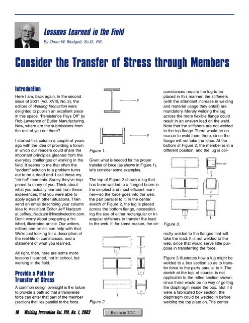
Figure 1.<br />
Given what is needed for <strong>the</strong> proper<br />
transfer <strong>of</strong> force (as shown in Figure 1),<br />
let’s consider some examples.<br />
Figure 2.<br />
Figure 3.<br />
The top <strong>of</strong> Figure 2 shows a lug that<br />
has been welded to a flanged beam in<br />
<strong>the</strong> simplest and most efficient manner—so<br />
<strong>the</strong> force goes into <strong>the</strong> web,<br />
<strong>the</strong> part parallel to it. In <strong>the</strong> center<br />
sketch <strong>of</strong> Figure 2, <strong>the</strong> lug is placed<br />
across <strong>the</strong> bottom flange, necessitating<br />
<strong>the</strong> use <strong>of</strong> ei<strong>the</strong>r rectangular or triangular<br />
stiffeners to transfer <strong>the</strong> load<br />
to <strong>the</strong> web. If, for some reason, <strong>the</strong> circumstances<br />
require <strong>the</strong> lug to be<br />
placed in this manner, <strong>the</strong> stiffeners<br />
(with <strong>the</strong> attendant increase in welding<br />
and material usage <strong>the</strong>y entail) are<br />
mandatory. Merely welding <strong>the</strong> lug<br />
across <strong>the</strong> more flexible flange could<br />
result in an uneven load on <strong>the</strong> weld.<br />
Note that <strong>the</strong> stiffeners are not welded<br />
to <strong>the</strong> top flange. There would be no<br />
reason to weld <strong>the</strong>m <strong>the</strong>re, since <strong>the</strong><br />
flange will not take <strong>the</strong> force. At <strong>the</strong><br />
bottom <strong>of</strong> Figure 2, <strong>the</strong> member is in a<br />
different position, and <strong>the</strong> lug is correctly<br />
welded to <strong>the</strong> flanges that will<br />
take <strong>the</strong> load. It is not welded to <strong>the</strong><br />
web, since that would serve little purpose<br />
in transferring <strong>the</strong> force.<br />
Figure 3 illustrates how a lug might be<br />
welded to a box section so as to transfer<br />
force to <strong>the</strong> parts parallel to it. The<br />
sketch at <strong>the</strong> top, <strong>of</strong> course, is not<br />
applicable to <strong>the</strong> rolled section shown,<br />
since <strong>the</strong>re would be no way <strong>of</strong> getting<br />
<strong>the</strong> diaphragm inside <strong>the</strong> box. But if it<br />
were a fabricated box section, <strong>the</strong><br />
diaphragm could be welded in before<br />
welding <strong>the</strong> top plate on. The center