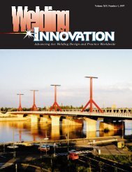
A publication of the James F. Lincoln Arc Welding Foundation
A publication of the James F. Lincoln Arc Welding Foundation
A publication of the James F. Lincoln Arc Welding Foundation

Create successful ePaper yourself
Turn your PDF publications into a flip-book with our unique Google optimized e-Paper software.
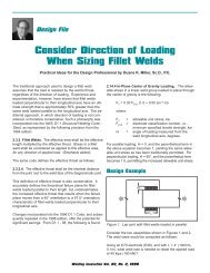
and bottom drawings in Figure 3 show<br />
additional ways to attach a lug to a<br />
box section. In <strong>the</strong> center, <strong>the</strong> lug is<br />
shaped as a sling and directly welded<br />
to <strong>the</strong> flange. At <strong>the</strong> bottom, <strong>the</strong> lug is<br />
designed so it will transfer <strong>the</strong> force<br />
into <strong>the</strong> two webs. This is a very efficient<br />
way to transfer <strong>the</strong> force on <strong>the</strong><br />
lug into <strong>the</strong> webs.<br />
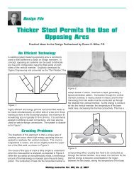
When <strong>the</strong> Member Is Circular<br />
Figure 4 illustrates two methods <strong>of</strong><br />
applying a transverse force to a circular<br />
member. The rationale for <strong>the</strong>se<br />
methods <strong>of</strong> attachment is shown in<br />
Figure 4.<br />
Figure 5. At <strong>the</strong> top <strong>of</strong> Figure 5, <strong>the</strong><br />
beam is welded to a support. In standard<br />
practice, it is assumed that <strong>the</strong><br />
flanges transfer <strong>the</strong> bending moments<br />
and <strong>the</strong> web transfers vertical shear. In<br />
<strong>the</strong> case <strong>of</strong> <strong>the</strong> circular member at <strong>the</strong><br />
Figure 5.<br />
bottom <strong>of</strong> Figure 5, however, it is difficult<br />
to decide which part <strong>of</strong> <strong>the</strong> member<br />
is flange, and which part is web.<br />
Ma<strong>the</strong>matical analysis has shown that<br />
if a tube is divided into four quadrants,<br />
<strong>the</strong> top and bottom quadrants will<br />
transfer 82% <strong>of</strong> <strong>the</strong> bending moment,<br />
and <strong>the</strong> side quadrants, 82% <strong>of</strong> <strong>the</strong><br />
vertical shear. The methods <strong>of</strong> attaching<br />
<strong>the</strong> lug shown in Figure 4, <strong>the</strong>refore,<br />
are methods that transfer force<br />
tending to cause vertical shear into <strong>the</strong><br />
areas <strong>of</strong> <strong>the</strong> circular section most<br />
closely parallel to <strong>the</strong> force.<br />
More Complicated Examples<br />
Figure 6 provides a more complicated<br />
example <strong>of</strong> force transfer. A tank to<br />
haul water on a truck is made up <strong>of</strong><br />
1/4 in. (6.4 mm) thick plate, with <strong>the</strong><br />
sides overlapping <strong>the</strong> ends so as to<br />
provide fillet welds. Considering <strong>the</strong><br />
forces from <strong>the</strong> water pressure on <strong>the</strong><br />
tank ends, <strong>the</strong> only place for <strong>the</strong>m to<br />
Figure 6.<br />
go is through <strong>the</strong> welds and into <strong>the</strong><br />
sides—<strong>the</strong> parts parallel to <strong>the</strong>ir direction.<br />
The forces get <strong>the</strong>re by bending<br />
<strong>the</strong> end plate. In service, <strong>the</strong> welds<br />
cracked. Three remedies were tried<br />
successively, as shown in Figure 6,<br />
using longitudinal and corner stiffeners,<br />
and finally both longitudinal and<br />
end stiffeners with corner stiffeners.<br />
Figure 7 shows <strong>the</strong> center sill <strong>of</strong> a<br />
piggyback railroad car to which a<br />
bracket is welded to carry a 500 lb.<br />
(227 kg) air compressor unit. There are<br />
no interior diaphragms. The vertical<br />
Figure 7.<br />
force from <strong>the</strong> weight <strong>of</strong> <strong>the</strong> unit is<br />
transferred as moment into <strong>the</strong> bracket,<br />
creating bending at <strong>the</strong> web. The two<br />
horizontal bending forces must eventually<br />
transfer to <strong>the</strong> parallel flanges, but<br />
with an open box section <strong>the</strong>re are no<br />
ready pathways. As a result, <strong>the</strong> web<br />
flexes and fatigue cracks appear in <strong>the</strong><br />
web. The sketches at <strong>the</strong> bottom <strong>of</strong><br />
Figure 7 illustrate two possible means<br />
for correcting <strong>the</strong> faulty design. In one,<br />
a stiffener is added before <strong>the</strong> web<br />
opposite <strong>the</strong> bracket side is welded<br />
into <strong>the</strong> assembly. The stiffener is welded<br />
to both flanges and to one web.<br />
There are now paths for <strong>the</strong> bending<br />
forces to get to <strong>the</strong> flanges. The second<br />
way to correct <strong>the</strong> design is to<br />
shape <strong>the</strong> bracket so it can be welded<br />
directly to <strong>the</strong> sill flanges in new fabrications,<br />
or to add pieces to <strong>the</strong> bracket<br />
on existing cars to accomplish <strong>the</strong><br />
same purpose.<br />
Conclusion<br />
The foregoing are just a few examples<br />
intended to illustrate <strong>the</strong> importance <strong>of</strong><br />
considering <strong>the</strong> transfer <strong>of</strong> force<br />
through members. Sometimes we<br />
engineers act a little like horses with<br />
blinders on: we concentrate so singlemindedly<br />
on <strong>the</strong> problem at hand, that<br />
we can’t see what is going on around<br />
us. The ideas discussed in this column<br />
should demonstrate how critical it is<br />
for us as engineers to take our blinders<br />
<strong>of</strong>f, expand our limited views, and<br />
test our assumptions.<br />
<strong>Welding</strong> Innovation Vol. XIX, No. 1, 2002 19