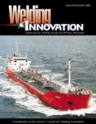
A publication of the James F. Lincoln Arc Welding Foundation
A publication of the James F. Lincoln Arc Welding Foundation
A publication of the James F. Lincoln Arc Welding Foundation

You also want an ePaper? Increase the reach of your titles
YUMPU automatically turns print PDFs into web optimized ePapers that Google loves.
from <strong>the</strong> German steel company<br />
Krupp, and in <strong>the</strong> bottom flange box<br />
section <strong>of</strong> bulb flats open ribs were utilized<br />
(Aune and Holand 1981). In <strong>the</strong><br />
longitudinal direction <strong>the</strong> deck was<br />
divided into six fabricated sections,<br />
two <strong>of</strong> which were welded to <strong>the</strong> web<br />
sections. The box bottom was fabricated<br />
as three sections. The total steel<br />
weight is about 1,100 tons. All elements<br />
prefabricated in <strong>the</strong> shop were<br />
welded, as were <strong>the</strong> field splices in <strong>the</strong><br />
deck, whereas “Huck” high tensile<br />
bolts were used in all o<strong>the</strong>r field joints.<br />
All field joints were calculated as friction<br />
connections. The whole steel<br />
structure is metallized with zinc and<br />
painted according to <strong>the</strong> specifications<br />
<strong>of</strong> <strong>the</strong> Norwegian Public Roads<br />
Administration. The superstructure<br />
received <strong>the</strong> maximum live load<br />
stresses during <strong>the</strong> erection <strong>of</strong> <strong>the</strong><br />
bridge. The wearing surface <strong>of</strong> <strong>the</strong><br />
bridge deck is <strong>the</strong> same as that developed<br />
by <strong>the</strong> Danish State Road<br />
Laboratories for <strong>the</strong> Lillebelt Bridge <strong>of</strong><br />
Denmark.<br />
Storda and Bomla Bridges<br />
The “Triangle Link” project connects<br />
three islands <strong>of</strong>f <strong>the</strong> Norwegian coast<br />
south <strong>of</strong> Belgen to <strong>the</strong> mainland with<br />
three bridges (Larson and Valen<br />
Researchers continue<br />
to monitor <strong>the</strong> performance<br />
<strong>of</strong> various rib types<br />
2000). The entire project was completed<br />
in April 2001. The two orthotropic<br />
steel deck suspension bridges are<br />
known as <strong>the</strong> Storda Bridge and <strong>the</strong><br />
Bomla Bridge. The Storda Bridge is<br />
1,076 m long, has a main span <strong>of</strong> 677<br />
m, with towers 97 m high and a vertical<br />
clearance <strong>of</strong> 18 m (Figure 6). The<br />
Bomla Bridge is 990 m long with a<br />
main span <strong>of</strong> 577 m and <strong>the</strong> tower<br />
height is 105 m. The roadway <strong>of</strong> both<br />
bridges is 9.7 m wide. Scanbridge AS<br />
<strong>of</strong> Norway fabricated <strong>the</strong> Bomla<br />
Bridge’s steel approach superstructure,<br />
which was launched out over <strong>the</strong><br />
tops <strong>of</strong> <strong>the</strong> columns from <strong>the</strong> shore.<br />
The steel components for <strong>the</strong> main<br />
span superstructure <strong>of</strong> <strong>the</strong> Storda<br />
Bridge were prefabricated in <strong>the</strong><br />
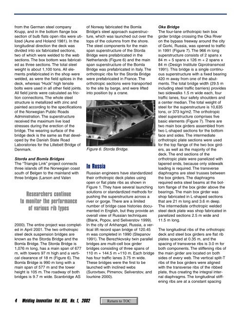
Ne<strong>the</strong>rlands (Figure 6) and <strong>the</strong> main<br />
span superstructure <strong>of</strong> <strong>the</strong> Bomla<br />
Bridge was prefabricated in Italy. The<br />
orthotropic ribs for <strong>the</strong> Storda Bridge<br />
were prefabricated in France. The<br />
orthotropic sections were transported<br />
to <strong>the</strong> site by barge, and were lifted<br />
into position by a crane.<br />
Figure 6. Storda Bridge.<br />
In Russia<br />
Russian engineers have standardized<br />
<strong>the</strong>ir orthotropic deck plates using<br />
open or flat plate ribs as shown in<br />
Figure 1. They have several launching<br />
solutions or standardized methods for<br />
pushing <strong>the</strong> superstructure across a<br />
river or gorge. There are a limited<br />
number <strong>of</strong> bridge case histories documented<br />
in English, but <strong>the</strong>y provide an<br />
overall view <strong>of</strong> Russian techniques<br />
(Blank, Popov, and Seliverstov 1999).<br />
In <strong>the</strong> city <strong>of</strong> Arkhangel, Russia, a vertical<br />
lift record span bridge <strong>of</strong> 120.45<br />
m was completed in 1990 (Stepanov<br />
1991). The Berezhkovsky twin parallel<br />
bridges are multi-cell box girder<br />
bridges consisting <strong>of</strong> three spans <strong>of</strong><br />
110 m + 144.5 m +110 m. Each bridge<br />
has four traffic lanes 3.75 m wide.<br />
These bridges were <strong>the</strong> first to be<br />
launched with inclined webs<br />
(Surovtsev, Pimenov, Seliverstov, and<br />
Iourkine 2000).<br />
Oka Bridge<br />
The four-lane orthotropic twin box<br />
girder bridge crossing <strong>the</strong> Oka River<br />
on <strong>the</strong> bypass freeway around <strong>the</strong> city<br />
<strong>of</strong> Gorki, Russia, was opened to traffic<br />
in 1991 (Figure 7). The 966 m long<br />
superstructure consists <strong>of</strong> 2 spans x<br />
84 m + 5 spans x 126 m + 2 spans x<br />
84 m (Design Institute Giprotransmost<br />
1991). This bridge is a single continuous<br />
superstructure with a fixed bearing<br />
420 m away from one <strong>of</strong> <strong>the</strong> abutments.<br />
The total bridge width (29.5 m<br />
including steel traffic barriers) provides<br />
two sidewalks 1.5 m wide each, four<br />
traffic lanes, four safety shoulders and<br />
a center median. The total weight <strong>of</strong><br />
steel for <strong>the</strong> superstructure is 10,635<br />
tons, or 373 kg/m2. The orthotropic<br />
steel superstructure comprises five<br />
basic elements (Figure 7). There are<br />
two main box girders assembled from<br />
two L-shaped sections for <strong>the</strong> bottom<br />
face and sides. The intermediate<br />
orthotropic plate sections were used<br />
for <strong>the</strong> top flange <strong>of</strong> <strong>the</strong> two box girders,<br />
as well as <strong>the</strong> majority <strong>of</strong> <strong>the</strong><br />
deck. The end sections <strong>of</strong> <strong>the</strong><br />
orthotropic plate were panelized with<br />
tapered ends, because only sidewalk<br />
loading is required. The transverse<br />
diaphragms are steel trusses between<br />
<strong>the</strong> box girders. The diaphragms<br />
required extra steel beams at <strong>the</strong> bottom<br />
flange <strong>of</strong> <strong>the</strong> box girder above <strong>the</strong><br />
bearings. The main box girder was<br />
shop fabricated in L-shaped sections<br />
that are 21 m long and 3.6 m deep.<br />
The intermediate orthotropic welded<br />
steel deck plate was shop fabricated in<br />
panelized sections 2.5 m wide and<br />
11.5 m long.<br />
The longitudinal ribs <strong>of</strong> <strong>the</strong> orthotropic<br />
deck and steel box girders are flat rib<br />
plates spaced at 0.35 m, and <strong>the</strong><br />
spacing <strong>of</strong> transverse ribs is 3.0 m for<br />
both components. The stiffening ribs <strong>of</strong><br />
<strong>the</strong> main girder are located on both<br />
sides <strong>of</strong> every web. The vertical split-T<br />
ribs <strong>of</strong> <strong>the</strong> box girders were aligned<br />
with <strong>the</strong> transverse ribs <strong>of</strong> <strong>the</strong> ribbed<br />
plate, thus creating <strong>the</strong> integral internal<br />
diaphragms. The longitudinal stiffening<br />
ribs are at a constant spacing<br />
4 <strong>Welding</strong> Innovation Vol. XIX, No. 1, 2002