A publication of the James F. Lincoln Arc Welding Foundation
A publication of the James F. Lincoln Arc Welding Foundation
A publication of the James F. Lincoln Arc Welding Foundation

You also want an ePaper? Increase the reach of your titles
YUMPU automatically turns print PDFs into web optimized ePapers that Google loves.
stayed bridge to <strong>the</strong> bridge deck 11 m<br />
above <strong>the</strong> waterline. The steel box<br />
girder <strong>of</strong> <strong>the</strong> floating bridge forms a<br />
circular arch with a radius <strong>of</strong> 1,700 m<br />
in <strong>the</strong> horizontal plane. The supporting<br />
pontoons are positioned with a center<br />
distance <strong>of</strong> 113 m and act as elastic<br />
supports for <strong>the</strong> girder, which is<br />
designed without internal hinges. The<br />
bridge follows <strong>the</strong> tidal variations by<br />
elastic deformations <strong>of</strong> <strong>the</strong> girder.<br />
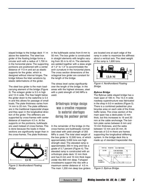
The steel box girder is <strong>the</strong> main loadcarrying<br />
element <strong>of</strong> <strong>the</strong> bridge (Figure<br />
3). The octagon girder is 5.5 m high<br />
and 13 m wide. The free height below<br />
<strong>the</strong> girder down to <strong>the</strong> waterline is 5.5<br />
m and this allows for passage <strong>of</strong> small<br />
boats. The plate thickness varies from<br />
14 mm to 20 mm. The plate stiffeners<br />
are in <strong>the</strong> traditional trapezoidal shape<br />
and <strong>the</strong>y span in <strong>the</strong> longitudinal direction<br />
<strong>of</strong> <strong>the</strong> girder. The stiffeners are<br />
supported by cross-frames with center<br />
distance <strong>of</strong> maximum 4.5 m. At <strong>the</strong><br />
supports on <strong>the</strong> pontoons, bulkheads<br />
are used instead <strong>of</strong> cross-frames. This<br />
is done because <strong>the</strong> loads in <strong>the</strong>se<br />
sections are significantly larger than in<br />
<strong>the</strong> cross-frames. The plate thickness<br />
Figure 3. Nordhordland Floating<br />
Bridge.<br />
in <strong>the</strong> bulkheads varies from 8 mm to<br />
50 mm. The box girder is constructed<br />
in straight elements with lengths varying<br />
from 35 m to 42 m. The elements<br />
are welded toge<strong>the</strong>r with a skew angle<br />
<strong>of</strong> 1.2° to 1.3° to accommodate <strong>the</strong><br />
arch curvature in <strong>the</strong> horizontal plane.<br />
The cross section dimensions <strong>of</strong> <strong>the</strong><br />
octagonal box girder are constant for<br />
<strong>the</strong> length <strong>of</strong> <strong>the</strong> bridge.<br />
The stress level varies significantly<br />
over <strong>the</strong> length <strong>of</strong> <strong>the</strong> bridge. In <strong>the</strong><br />
areas with <strong>the</strong> highest stresses, steel<br />
with a yield strength <strong>of</strong> 540 MPa is<br />
used.<br />
Orthotropic bridge design<br />
was a creative response<br />
to material shortages<br />
during <strong>the</strong> postwar period<br />
In <strong>the</strong> remainder <strong>of</strong> <strong>the</strong> bridge (in <strong>the</strong><br />
cross-frames and bulkheads) normalized<br />
steel with yield strength <strong>of</strong> 355<br />
MPa is used. The total steel weight <strong>of</strong><br />
<strong>the</strong> box girder is 12,500 tons, <strong>of</strong> which<br />
approximately 3,000 tons are high<br />
strength steel. The elevated ramp is<br />
approximately 350 m long and has a<br />
grade <strong>of</strong> 5.7 percent (Figure 4). The<br />
elevated ramp is constructed with an<br />
orthotropic plate deck 12 mm thick<br />
and has 8 mm and 10 mm thick trapezoidal<br />
ribs 800 mm deep. T-shaped<br />
crossbeams support <strong>the</strong> ribs with a<br />
maximum center distance <strong>of</strong> 4.5 m.<br />
The main 1,200 mm deep box girders<br />
are located one at each edge <strong>of</strong> <strong>the</strong><br />
ramp in order to maximize <strong>the</strong> stiffness<br />
about a vertical axis. The steel weight<br />
<strong>of</strong> <strong>the</strong> ramp is 1,600 tons.<br />
Figure 4. Nordhordland Floating<br />
Bridge.<br />
Bybrua Bridge<br />
The Bybrua cable stayed bridge has a<br />
main span <strong>of</strong> 185 m. The 15.5 m wide<br />
roadway superstructure was fabricated<br />
in <strong>the</strong> shop in 9.0 m sections (Figure 5).<br />
There is a combined pedestrian plus<br />
bicycles area on each side <strong>of</strong> <strong>the</strong> three<br />
traffic lanes. The cross section <strong>of</strong> <strong>the</strong><br />
main span has a deck-plate 12 mm<br />
thick, but this increases to 16 and 20<br />
mm at <strong>the</strong> cable anchorage. The bottom<br />
plate varies between 8 mm and<br />
10 mm thickness, and <strong>the</strong> webs<br />
between 12 mm and 20 mm. At<br />
intervals <strong>of</strong> 3.0 m <strong>the</strong>re are frames<br />
supporting <strong>the</strong> longitudinal stiffening<br />
system. In <strong>the</strong> bridge deck this is<br />
made up <strong>of</strong> standard trapezoidal ribs<br />
Figure 5. Bybrua Bridge.<br />
<strong>Welding</strong> Innovation Vol. XIX, No. 1, 2002 3