A publication of the James F. Lincoln Arc Welding Foundation
A publication of the James F. Lincoln Arc Welding Foundation
A publication of the James F. Lincoln Arc Welding Foundation

Create successful ePaper yourself
Turn your PDF publications into a flip-book with our unique Google optimized e-Paper software.
Design File<br />
Designing Fillet Welds for Skewed T-joints—Part 1<br />
Practical Ideas for <strong>the</strong> Design Pr<strong>of</strong>essional by Duane K. Miller, Sc.D., P.E.<br />
Introduction<br />
Detailing fillet welds for 90-degree T-joints is a fairly<br />
straightforward activity. Take <strong>the</strong> 90-degree T-joint and skew<br />
it—that is, rotate <strong>the</strong> upright member so as to create an<br />
acute and obtuse orientation, and <strong>the</strong> resultant geometry<br />
<strong>of</strong> <strong>the</strong> fillet welds becomes more complicated (see Figure<br />
1). The greater <strong>the</strong> degree <strong>of</strong> rotation, <strong>the</strong> greater <strong>the</strong> difference<br />
as compared to <strong>the</strong> 90-degree counterpart.<br />
A series <strong>of</strong> equations can be used to determine weld sizes<br />
for various angular orientations and required throat dimensions.<br />
Since <strong>the</strong> weld sizes on ei<strong>the</strong>r side <strong>of</strong> <strong>the</strong> joint are<br />
not necessarily required to be <strong>of</strong> <strong>the</strong> same size, <strong>the</strong>re are a<br />
variety <strong>of</strong> combinations that can be used to transfer <strong>the</strong><br />
loads across <strong>the</strong> joint. While <strong>the</strong>re are <strong>the</strong>oretical savings<br />
to be seen by optimizing <strong>the</strong> combinations <strong>of</strong> weld sizes,<br />
rarely do such efforts result in a change in fillet weld size <strong>of</strong><br />
even one standard size.<br />
Codes prescribe different methods <strong>of</strong> indicating <strong>the</strong><br />
required weld size. These are summarized herein.<br />
When acute angles become smaller, <strong>the</strong> difficulty <strong>of</strong><br />
achieving a quality weld in <strong>the</strong> root increases. The AWS<br />
D1.1 Structural <strong>Welding</strong> Code deals with this issue by<br />
requiring <strong>the</strong> consideration <strong>of</strong> a Z-loss factor.<br />
This edition <strong>of</strong> Design File addresses <strong>the</strong> situation where<br />
<strong>the</strong> end <strong>of</strong> <strong>the</strong> upright member in <strong>the</strong> skewed T-joint is parallel<br />
to <strong>the</strong> surface <strong>of</strong> <strong>the</strong> o<strong>the</strong>r member. A future Design<br />
File column will consider <strong>the</strong> situation in which <strong>the</strong> upright<br />
member has a square cut on <strong>the</strong> end, resulting in a gap on<br />
<strong>the</strong> obtuse side. Also to be addressed in <strong>the</strong> future are<br />
weld options o<strong>the</strong>r than fillet welds in skewed T-joints.<br />
LEG<br />
SIZE<br />
DIHEDRAL ANGLE<br />
0<br />
135 MAX<br />
ω 2<br />
ω 1<br />
ψ 2<br />
ω ψ 1<br />
1<br />
f 2<br />
ω 2<br />
b 2 b 1<br />
f 1<br />
t 2<br />
t 1<br />
b 2<br />
b 1<br />
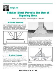
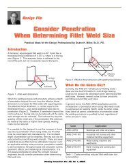
Figure 1. Equal throat sizes (t 1 = t 2 ).<br />
DIHEDRAL<br />
ANGLE<br />
0<br />
60 MIN<br />
The Geometry<br />
Figure 1 provides a visual representation <strong>of</strong> <strong>the</strong> issue. For<br />
<strong>the</strong> 90-degree orientation, <strong>the</strong> weld throat is 70.7% <strong>of</strong> <strong>the</strong><br />
weld leg dimension. This relationship does not hold true for<br />
fillet welds in skewed joints. On <strong>the</strong> obtuse side, <strong>the</strong> weld<br />
throat is smaller than what would be expected for a fillet<br />
weld <strong>of</strong> a similar leg size in a 90-degree joint, and <strong>the</strong><br />
opposite is <strong>the</strong> case for <strong>the</strong> acute side. These factors must<br />
be considered when <strong>the</strong> fillet weld leg size is determined<br />
and specified.<br />
Careful examination <strong>of</strong> <strong>the</strong> fillet welds on <strong>the</strong> skewed joint<br />
raises this question: What is <strong>the</strong> size <strong>of</strong> <strong>the</strong> fillet weld in a<br />
skewed joint?<br />
LEG<br />
SIZE<br />
Figure 1 illustrates <strong>the</strong> fillet weld leg size for a skewed T-<br />
joint, and is designated by “ω.” This, however, is inconsistent<br />
with AWS Terms and Definitions (AWS A3.0-94) which<br />
defines a “fillet weld leg” as “The distance from <strong>the</strong> joint<br />
root to <strong>the</strong> toe <strong>of</strong> <strong>the</strong> fillet weld.” According to this definition,<br />
and as shown in Figure 1, <strong>the</strong> fillet weld leg is dimension<br />
“b.” The dimension that is labeled “ω” is <strong>the</strong> distance from a<br />
member to a parallel line extended from <strong>the</strong> bottom weld<br />
<strong>Welding</strong> Innovation Vol. XIX, No. 1, 2002 7