A publication of the James F. Lincoln Arc Welding Foundation
A publication of the James F. Lincoln Arc Welding Foundation
A publication of the James F. Lincoln Arc Welding Foundation

Create successful ePaper yourself
Turn your PDF publications into a flip-book with our unique Google optimized e-Paper software.
Obtuse angles greater than 100 degrees<br />
For this category, contract drawings should show <strong>the</strong><br />
required effective throat. Shop drawings are to show <strong>the</strong><br />
required leg dimension, calculated with equation 1, or by<br />
using columns C or D <strong>of</strong> Table 1 (AWS D1.1-2002, para<br />
2.2.5.2, 2.3.3.2).<br />
Angles <strong>of</strong> 80–100 degrees<br />
For this group, shop drawings are required to show <strong>the</strong><br />
fillet leg size (AWS D1.1-2002, para 2.2.5.2). While not<br />
specifically stated in <strong>the</strong> code, <strong>the</strong> assumption is that<br />
contract drawings also show this dimension.<br />
Angles <strong>of</strong> 60–80 degrees<br />
For this category, contract drawings should show <strong>the</strong><br />
required effective throat. Shop drawings are to show <strong>the</strong><br />
required leg dimension (AWS D1.1-2002, para 2.2.5.2,<br />
2.3.3.2)<br />
Angles <strong>of</strong> 30–60 degrees<br />
Contract drawings are to show <strong>the</strong> effective throat. Shop<br />
drawings are required to “show <strong>the</strong> required leg dimensions<br />
to satisfy <strong>the</strong> required effective throat, increased by <strong>the</strong> Z-<br />
loss allowance ... ” (AWS D1.1-2002, para 2.2.5.2, 2.3.3.3).<br />
The Z-loss factor is used to account for <strong>the</strong> likely incidence<br />
<strong>of</strong> poor quality welding in <strong>the</strong> root <strong>of</strong> a joint with a small<br />
included angle. The amount <strong>of</strong> poor quality weld in <strong>the</strong> root<br />
<strong>of</strong> <strong>the</strong> joint is a function <strong>of</strong> <strong>the</strong> dihedral angle, <strong>the</strong> welding<br />
process, and <strong>the</strong> position <strong>of</strong> welding. Table 2.2 <strong>of</strong> D1.1<br />
summarizes this data as contained below:<br />
Table 2. Z-loss dimension.<br />
60 o >Ψ > 45 o FCAW-S 1/8 3 FCAW-S 0 0<br />
FCAW-G 1/8 3 FCAW-G 0 0<br />
Position <strong>of</strong> <strong>Welding</strong> Position <strong>of</strong> <strong>Welding</strong><br />
V or OH<br />
H or F<br />
Dihedral Angle Ψ Process Z (in.) Z (mm) Process Z (in.) Z (mm)<br />
SMAW 1/8 3 SMAW 1/8 3<br />
GMAW N/A N/A GMAW 0 0<br />
45 o >Ψ > 30 o<br />
SMAW 1/4 6 SMAW 1/4 6<br />
FCAW-S 1/4 6 FCAW-S 1/8 3<br />
FCAW-G 3/8 10 FCAW-G 1/4 6<br />
GMAW N/A N/A GMAW 1/4 6<br />
Once <strong>the</strong> Z-loss dimension has been determined, it is added<br />
to <strong>the</strong> required throat dimension. Even though part <strong>of</strong> <strong>the</strong><br />
weld in <strong>the</strong> root is considered to be <strong>of</strong> such poor quality as<br />
to be incapable <strong>of</strong> transferring stress, <strong>the</strong> resultant weld will<br />
contain sufficient quality weld metal to permit <strong>the</strong> transfer <strong>of</strong><br />
imposed loads. Figure 4 illustrates this concept.<br />
The data in Table 1 that applies to dihedral angles <strong>of</strong><br />
30–60 degrees has been shown in blue numbers because<br />
<strong>the</strong>se values must be modified to account for <strong>the</strong> Z-loss<br />
factors. Such a modification has not been done for <strong>the</strong> data<br />
in <strong>the</strong> Table.<br />
Z<br />
Figure 4. Z-loss.<br />
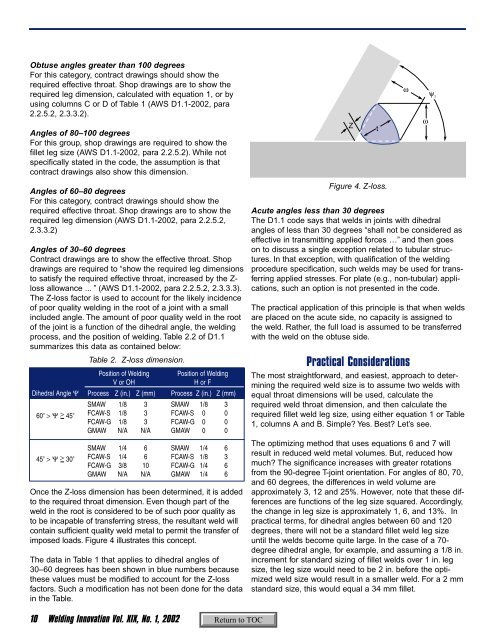
Acute angles less than 30 degrees<br />
The D1.1 code says that welds in joints with dihedral<br />
angles <strong>of</strong> less than 30 degrees “shall not be considered as<br />
effective in transmitting applied forces …” and <strong>the</strong>n goes<br />
on to discuss a single exception related to tubular structures.<br />
In that exception, with qualification <strong>of</strong> <strong>the</strong> welding<br />
procedure specification, such welds may be used for transferring<br />
applied stresses. For plate (e.g., non-tubular) applications,<br />
such an option is not presented in <strong>the</strong> code.<br />
The practical application <strong>of</strong> this principle is that when welds<br />
are placed on <strong>the</strong> acute side, no capacity is assigned to<br />
<strong>the</strong> weld. Ra<strong>the</strong>r, <strong>the</strong> full load is assumed to be transferred<br />
with <strong>the</strong> weld on <strong>the</strong> obtuse side.<br />
Practical Considerations<br />
The most straightforward, and easiest, approach to determining<br />
<strong>the</strong> required weld size is to assume two welds with<br />
equal throat dimensions will be used, calculate <strong>the</strong><br />
required weld throat dimension, and <strong>the</strong>n calculate <strong>the</strong><br />
required fillet weld leg size, using ei<strong>the</strong>r equation 1 or Table<br />
1, columns A and B. Simple? Yes. Best? Let’s see.<br />
The optimizing method that uses equations 6 and 7 will<br />
result in reduced weld metal volumes. But, reduced how<br />
much? The significance increases with greater rotations<br />
from <strong>the</strong> 90-degree T-joint orientation. For angles <strong>of</strong> 80, 70,<br />
and 60 degrees, <strong>the</strong> differences in weld volume are<br />
approximately 3, 12 and 25%. However, note that <strong>the</strong>se differences<br />
are functions <strong>of</strong> <strong>the</strong> leg size squared. Accordingly,<br />
<strong>the</strong> change in leg size is approximately 1, 6, and 13%. In<br />
practical terms, for dihedral angles between 60 and 120<br />
degrees, <strong>the</strong>re will not be a standard fillet weld leg size<br />
until <strong>the</strong> welds become quite large. In <strong>the</strong> case <strong>of</strong> a 70-<br />
degree dihedral angle, for example, and assuming a 1/8 in.<br />
increment for standard sizing <strong>of</strong> fillet welds over 1 in. leg<br />
size, <strong>the</strong> leg size would need to be 2 in. before <strong>the</strong> optimized<br />
weld size would result in a smaller weld. For a 2 mm<br />
standard size, this would equal a 34 mm fillet.<br />
t<br />
ω<br />
ω<br />
ψ 1<br />
10 <strong>Welding</strong> Innovation Vol. XIX, No. 1, 2002