VAV Controllers LVC-LowVelocity - TROX
VAV Controllers LVC-LowVelocity - TROX
VAV Controllers LVC-LowVelocity - TROX

You also want an ePaper? Increase the reach of your titles
YUMPU automatically turns print PDFs into web optimized ePapers that Google loves.
5/5/EN/1<br />
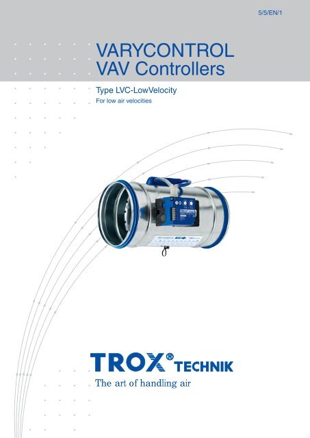
VARYCONTROL<br />
<strong>VAV</strong> <strong>Controllers</strong><br />
Type <strong>LVC</strong>-<strong>LowVelocity</strong><br />
For low air velocities<br />
The art of handling air
Contents<br />
Innovation __________________________________ 3<br />
Functional description__________________________ 4<br />
Construction · Dimensions ______________________ 5<br />
Nomenclature · Selection of nominal size __________ 6<br />
Acoustic quick selection ________________________ 7<br />
Air-regenerated noise __________________________ 8<br />
Case-radiated noise __________________________ 9<br />
Flow rate setting ______________________________10<br />
Flow characteristics · Wiring examples ____________11<br />
Order details ________________________________12<br />
1 Select nominal size Set flow rates<br />
2<br />
3<br />
Green light: Ready!<br />
2
Innovation<br />
<strong>TROX</strong> <strong>LVC</strong>-<strong>LowVelocity</strong> – the innovative solution<br />
■<br />
■<br />
Optimised for low air velocities of 0.6 to 6 m/s<br />
High control accuracy even in case of unfavourable<br />
upstream flow conditions<br />
■ Casing length of only 310 mm<br />
■ Selection according to the nominal size of the duct<br />
■ Indicator light provides functional information<br />
The innovative concept of the type <strong>LVC</strong>-<strong>LowVelocity</strong> controllers<br />
provides accurate measurement and control of low volume flow<br />
rates based on the differential pressure principle.<br />
The differential pressure is the result of two measurements,<br />
one upstream and one downstream of the damper blade. This<br />
setup makes it possible to measure larger differential pressures,<br />
especially in the case of low volume flow rates. The relation<br />
between damper blade position and differential pressure is<br />
stored as a characteristic relationship in the Compact controller.<br />
<strong>LVC</strong>-<strong>LowVelocity</strong>: simple, accurate, reliable!<br />
1<br />
2<br />
<br />
<br />
3<br />
9<br />
8<br />
4 5 6 7<br />
1 Casing<br />
2 Double lip seal<br />
3 Plastic nozzle with damper blade<br />
4 Flow rate scale<br />
5 Wire clamping bracket<br />
6 <strong>TROX</strong> Compact controller<br />
7 Connection terminals<br />
8 Protective cover<br />
9 Indicator light<br />
Potentiometers<br />
Damper blade shaft end<br />
(indicates blade position)<br />
3
Functional description<br />
Volume flow rate measurement<br />
A new measurement principle makes it possible to measure<br />
low volume flow rates. The pressure is measured by means<br />
of a nozzle with tappings upstream and downstream of the<br />
damper blade. The Compact controller of the <strong>LVC</strong>-<strong>LowVelocity</strong><br />
determines the resulting pressure differential (effective pressure)<br />
and compares it to the stored characteristic.<br />
This measurement principle is characterised by small measuring<br />
tolerances, and the upstream flow conditions do not have to<br />
meet any special requirements.<br />
Volume flow rate control<br />
The volume flow rate is controlled in a closed loop,<br />
i.e. measurement – comparison – control.<br />
First, measurement takes place. The controller then compares<br />
the actual measured value to the setpoint value, which in most<br />
applications is received from a room temperature controller. In<br />
case of a deviation, the controller sends a signal to the actuator,<br />
and the actuator moves the damper blade accordingly.<br />
Room temperature control<br />
In <strong>VAV</strong> systems, the room temperature control takes the form<br />
of a cascade control. The room temperature is the primary<br />
controlled variable. The output signal from the room temperature<br />
controller controls the supply air flow rate. Flow rate control also<br />
means defining minimum and maximum flow rates, and not only<br />
does this help to keep the room temperature constant but has<br />
advantages for the entire air conditioning system.<br />
Supply/extract air tracking control<br />
In individual rooms the balance between supply and extract air<br />
should be maintained. Otherwise, annoying whistling noises<br />
can occur at door gaps, and the doors can be difficult to open.<br />
This is also why the extract air is controlled in a <strong>VAV</strong> system<br />
(tracking control). The actual supply air value is fed to the<br />
extract air controller, and the extract air consequently follows<br />
the supply air flow rate even when the supply air deviates<br />
from the setpoint value.<br />
Control principle<br />
Control diagram<br />
V Nom<br />
V max<br />
2<br />
3<br />
1<br />
Setpoint value<br />
<strong>TROX</strong> Compact controller<br />
Vmin<br />
V min unit<br />
1 Volume flow controller<br />
2 Differential pressure transducer<br />
3 Actuator<br />
Control signal for the <strong>VAV</strong> controller<br />
Upstream flow conditions<br />
Upstream bend<br />
Branch off the main duct<br />
1 D<br />
D<br />
4
Construction · Dimensions<br />
Characteristics<br />
– Electronic flow rate control<br />
– Suitable for supply and extract air<br />
– High control accuracy, even in case of unfavourable upstream<br />
flow conditions<br />
– Differential pressure range: 30 to 600 Pa<br />
– Shut-off by means of a switch (supplied by customer)<br />
– Leakage when the damper blade is closed complies<br />
with EN 1751, class 3<br />
– Any installation orientation is possible<br />
– Transparent protective cover for general safety and to prevent<br />
inadvertent resetting<br />
– Wire clamping bracket<br />
– Factory setting and aerodynamic function testing of every<br />
individual unit on a special test rig<br />
Construction features<br />
– Both spigot connections with lip seals, suitable for ducts<br />
according to EN 1506 or EN 13180<br />
– Casing air leakage complies with EN 1751, class C<br />
– Mechanical parts of the <strong>VAV</strong> controller are maintenance-free<br />
Materials<br />
– Casing in galvanised sheet steel<br />
– Nozzle, damper blade, and plain bearings made of<br />
ABS plastic, UL 94, flame retardant (V0)<br />
– Damper blade seal made of TPV plastic<br />
General Information<br />
Standard filtration in comfort conditioning systems is such that<br />
the <strong>TROX</strong> Compact controller can be used in the supply air<br />
without additional dust protection. To select volume flow<br />
controllers for dust laden or aggressive extract air refer to the<br />
Easy Product Finder design programme on our homepage.<br />
Dimensions<br />
310<br />
50 50<br />
300<br />
Ø Da<br />
300<br />
20<br />
76<br />
Keep clear to provide access to<br />
control components<br />
Dimensions in mm<br />
Nominal size ØDa<br />
125 124<br />
160 159<br />
200 199<br />
250 249<br />
Weight in kg<br />
Nominal size<br />
125 1.5<br />
160 1.9<br />
200 2.1<br />
250 2.7<br />
<strong>TROX</strong> Compact controller – Technical data<br />
Supply voltage<br />
Power rating<br />
Control signal<br />
Flow rate actual value<br />
signal<br />
IEC protection class<br />
Protection level IP 20<br />
24 V AC ± 20 %, 50/60 Hz or<br />
24 V DC −10 % / +20 %<br />
5 VA max. (for AC voltage)<br />
3 W max. (for DC voltage)<br />
0 to 10 V DC, Ri > 100kΩ<br />
0 to 10 V DC linear, 0.5 mA max.<br />
III (Safety Extra Low Voltage, SELV)<br />
5
Nomenclature · Selection of nominal size<br />
Nomenclature<br />
fm<br />
in Hz : Octave band centre frequency<br />
LPA in dB(A) : A-weighted sound pressure level of<br />
air-regenerated noise, system<br />
attenuation taken into account<br />
LPA₁ in dB(A) : A-weighted sound pressure level of<br />
air-regenerated noise in the room with<br />
CS circular silencer, system attenuation<br />
taken into account<br />
LPA₂ in dB(A) : A-weighted sound pressure level of<br />
case-radiated noise, system attenuation<br />
taken into account<br />
LW<br />
in dB : Sound power level of the air-regenerated<br />
noise in the duct<br />
LW₂<br />
in dB : Sound power level of the case-radiated<br />
noise<br />
V Nom in l/s and m³/h : Nominal flow rate (100 %)<br />
V in l/s and m³/h : Volume flow rate<br />
∆V in ± % : Flow rate tolerance from setpoint value<br />
Vmin in l/s and m³/h : Set minimum volume flow rate<br />
V max in l/s and m³/h : Set maximum volume flow rate<br />
V min unit in l/s und m³/h : Minimum volume flow rate for unit<br />
∆pst<br />
in Pa : Static pressure differential<br />
∆pst min in Pa : Static minimum pressure differential<br />
All sound power levels are based on 1 pW, all sound pressure<br />
levels on 20µPa.<br />
All noise levels were determined in a reverberation chamber.<br />
The sound power data has been determined and corrected<br />
according to EN ISO 5135, February 1999.<br />
Technical data based on an air density of 1.2 kg/m³.<br />
10 20 30 40 50 60 70 80 90 100<br />
Vmin<br />
10 20 30 40 50 60 70 80 90 100<br />
Air flow velocity<br />
in m/s (approx.)<br />
0.6 1.2 1.8 2.4 3.0 3.6 4.2 4.8 5.2 6.0<br />
V max<br />
Nominal<br />
size<br />
125<br />
l/s 8 15 25 30 40 45 55 60 70 75<br />
m³/h 30 55 80 110 135 160 190 215 245 270<br />
160<br />
l/s 12 25 35 50 60 70 85 95 110 120<br />
m³/h 45 85 130 170 215 260 300 345 385 430<br />
200<br />
l/s 20 40 55 75 95 115 135 150 170 190<br />
m³/h 70 135 205 275 340 410 480 550 615 685<br />
250<br />
l/s 30 60 90 120 150 180 210 240 270 300<br />
m³/h 110 215 325 430 540 650 755 865 970 1080<br />
6
Acoustic quick selection<br />
Using quick selection for sizing <strong>VAV</strong> controllers will rapidly<br />
provide optimum results. The first selection criteria are the given<br />
volume flow rates Vmin and V max . The expected sound pressure<br />
level in the room is then determined from the static pressure<br />
differential. The quick selection tables are based on normally<br />
accepted attenuation levels; if the sound pressure level exceeds<br />
the required level, a larger volume flow controller and/or a<br />
silencer is required.<br />
For dimensions and technical data for type CS sound<br />
attenuators refer to leaflet 6/5/EN/....<br />
For a more detailed selection and design of<br />
type <strong>LVC</strong>-<strong>LowVelocity</strong> <strong>VAV</strong> controllers refer to the<br />
Easy Product Finder design programme on our homepage.<br />
System attenuation in dB/oct. acc. to VDI 2081<br />
(values incorporated in the quick selection table)<br />
fm in Hz<br />
63<br />
Duct bend 0 0 1 2 3 3 3 3<br />
Room attenuation 5 5 5 5 5 5 5 5<br />
End reflection 10 5 2 0 0 0 0 0<br />
125<br />
250<br />
500<br />
Correction for distribution into the duct system<br />
(values incorporated in the quick selection table)<br />
V<br />
1000<br />
2000<br />
4000<br />
l/s 150 200 250 300<br />
m³/h 540 720 900 1080<br />
dB per octave 0 1 2 3<br />
8000<br />
4 dB/octave ceiling reduction and 5 dB/octave room attenuation<br />
have been allowed for in the calculation of case-radiated noise.<br />
Quick selection of sound pressure level LPA in dB(A)<br />
Air-regenerated noise<br />
Case-radiated<br />
noise<br />
Nominal<br />
size<br />
V<br />
∆pst<br />
min<br />
∆V<br />
∆pst in Pa ∆pst in Pa ∆pst in Pa ∆pst ∆pst in Pa<br />
50 150 300 50 150 300 50 150 300 300 50 150 300<br />
Without CS<br />
CS050<br />
L = 500<br />
CS050<br />
L = 1000<br />
CS050<br />
L = 1500<br />
LPA LPA₁ LPA₁ LPA₁ LPA₂<br />
l/s m³/h Pa ±% dB(A) dB(A) dB(A) dB(A) dB(A)<br />
8 30 30 15 27 37 43 14 22 28 4 10 15 10 9 21 30<br />
125<br />
30 110 30 12 35 45 51 24 33 39 17 24 29 26 16 27 34<br />
55 200 30 8 39 49 55 30 39 44 24 31 36 33 20 30 38<br />
75 270 30 5 42 52 58 34 42 48 29 36 41 38 22 33 40<br />
12 45 30 15 28 38 45 19 28 34 12 19 24 20 8 20 28<br />
160<br />
50 180 30 12 34 44 51 25 34 40 19 27 32 28 17 28 36<br />
85 305 30 8 36 46 54 29 37 43 23 31 36 33 21 32 39<br />
120 430 30 5 38 48 56 21 39 45 28 34 39 36 23 34 42<br />
20 70 30 15 31 40 47 21 30 36 13 20 26 23 10 21 29<br />
200<br />
75 270 30 12 35 45 52 25 34 42 19 26 32 29 17 29 37<br />
135 485 30 8 36 47 54 28 37 44 22 29 35 33 21 32 40<br />
190 685 30 5 36 47 55 29 37 45 26 31 36 35 23 34 42<br />
30 110 30 15 31 41 48 24 32 40 17 25 32 30 16 27 34<br />
250<br />
120 430 30 12 36 47 54 28 38 46 21 30 38 35 24 35 42<br />
210 755 30 8 36 47 55 28 39 47 23 31 39 36 27 38 46<br />
300 1080 30 5 36 48 55 29 39 48 25 32 39 37 29 40 48<br />
7
Air-regenerated noise<br />
1<br />
LW₂<br />
LW<br />
2<br />
LPA<br />
LPA₁<br />
3<br />
4<br />
5<br />
Example<br />
Given: V max = 50 l/s (180 m³/h)<br />
∆pst = 150 Pa<br />
Required sound pressure level in the<br />
room 45 dB(A)<br />
For further assumptions, see calculation<br />
Calculation<br />
Quick selection:<br />
<strong>LVC</strong>-<strong>LowVelocity</strong> / 160<br />
Air-regenerated noise<br />
LPA = 44 dB(A)<br />
Case-radiated noise<br />
LPA₂ = 28 dB(A)<br />
LPA₂<br />
1 <strong>LVC</strong>-<strong>LowVelocity</strong><br />
2 Circular silencer CS/CF<br />
3 Air distribution to several diffusers<br />
4 Duct bend<br />
5 End reflection based on diffuser<br />
Nominal<br />
size<br />
V<br />
Air-regenerated noise<br />
∆pst = 50 Pa ∆pst = 150 Pa ∆pst = 300 Pa<br />
LW in dB LW in dB LW in dB<br />
fm in Hz fm in Hz fm in Hz<br />
l/s<br />
m³/h<br />
63<br />
125<br />
250<br />
500<br />
1000<br />
2000<br />
4000<br />
8000<br />
63<br />
125<br />
250<br />
500<br />
1000<br />
2000<br />
4000<br />
8000<br />
63<br />
125<br />
250<br />
500<br />
1000<br />
2000<br />
4000<br />
8000<br />
8 30 42 29 29 36 27 16 4 7 44 36 39 45 39 31 17 22 45 41 45 50 47 41 26 31<br />
125<br />
30 110 55 47 44 43 33 27 19 14 57 54 53 52 45 42 32 29 59 59 59 58 53 51 41 38<br />
55 200 61 55 50 47 36 31 26 17 63 62 59 55 48 46 39 32 65 67 65 61 56 56 47 41<br />
75 270 64 59 54 49 38 34 30 19 67 67 63 57 50 49 43 34 68 71 69 63 57 58 51 43<br />
12 45 41 30 40 36 27 19 22 7 45 68 47 45 39 35 35 25 47 43 51 50 46 45 43 37<br />
160<br />
50 180 49 45 46 40 34 27 26 13 53 53 53 49 45 43 39 32 55 58 58 55 53 53 48 44<br />
85 305 52 51 48 42 36 31 28 16 56 59 56 51 48 46 41 35 58 64 60 57 56 56 49 46<br />
120 430 54 55 50 44 38 33 29 18 58 63 57 52 50 48 42 36 60 68 62 58 57 58 50 48<br />
20 70 42 31 40 39 30 23 19 8 44 39 46 48 41 38 34 24 45 44 50 53 48 48 53 35<br />
200<br />
75 270 53 44 44 42 36 30 24 14 55 52 50 50 47 45 39 30 56 58 54 56 54 55 48 41<br />
135 485 58 49 45 43 38 33 26 16 60 58 51 51 49 48 41 33 61 63 55 57 56 58 50 43<br />
190 685 61 52 46 43 40 35 28 18 63 61 52 52 51 50 42 35 64 66 56 57 58 60 52 45<br />
30 110 35 33 43 38 31 28 20 13 42 41 49 46 42 42 37 30 46 47 52 51 49 50 47 41<br />
250<br />
120 430 47 45 45 41 37 37 25 18 54 53 51 49 48 50 42 35 58 59 55 54 55 58 52 46<br />
210 755 52 50 46 42 40 40 27 20 58 58 52 50 50 53 44 37 62 64 56 56 57 62 54 48<br />
300 1080 55 53 47 43 41 42 29 22 61 61 53 51 52 55 45 39 65 67 57 56 59 64 56 49<br />
8
Case-radiated noise<br />
Example (contd.)<br />
Calculation of air-regenerated noise<br />
fm 63 125 250 500 1000 2000 4000 8000<br />
LW 53 53 53 49 45 43 39 32<br />
Distribution 0 0 0 0 0 0 0 0<br />
Duct bend 0 0 1 2 3 3 3 3<br />
End reflection 10 5 2 0 0 0 0 0<br />
Sound power level<br />
to room<br />
43 48 50 47 42 40 36 29<br />
Room attenuation 6 6 5 5 4 4 4 4<br />
A-weighting −26 −16 −9 −3 0 1 1 −1<br />
Corrected level 11 26 36 39 38 37 33 24<br />
LPA 44<br />
Calculation of case-radiated noise<br />
fm 63 125 250 500 1000 2000 4000 8000<br />
LW₂ 30 23 25 29 33 32 25 24<br />
Ceiling attenuation 4 4 4 4 4 4 4 4<br />
Room attenuation 6 6 5 5 4 4 4 4<br />
A-weighting −26 −16 −9 −3 0 1 1 −1<br />
Corrected level 0 0 7 17 25 25 18 15<br />
LPA₂ 29<br />
In a variation from the quick selection, different room attenuation<br />
values have been assumed.<br />
The logarithmic addition of air-regenerated noise and<br />
case-radiated noise equals 44 dB(A) and does therefore not<br />
exceed the required sound pressure level of 45 dB(A).<br />
Nominal<br />
size<br />
V<br />
Case-radiated noise<br />
∆pst = 50 Pa ∆pst = 150 Pa ∆pst = 300 Pa<br />
LW₂ in dB LW₂ in dB LW₂ in dB<br />
fm in Hz fm in Hz fm in Hz<br />
l/s<br />
m³/h<br />
63<br />
125<br />
250<br />
500<br />
1000<br />
2000<br />
4000<br />
8000<br />
63<br />
125<br />
250<br />
500<br />
1000<br />
2000<br />
4000<br />
8000<br />
63<br />
125<br />
250<br />
500<br />
1000<br />
2000<br />
4000<br />
8000<br />
8 30 25 6 7 12 14 4 7 13 26 14 16 20 24 18 21 28 27 18 21 26 30 26 29 38<br />
125<br />
30 110 28 18 19 21 22 15 13 10 29 25 27 29 32 29 27 25 30 30 33 35 38 37 35 35<br />
55 200 29 23 24 25 26 20 16 8 31 30 32 33 35 33 29 24 31 35 38 39 42 42 38 33<br />
75 270 30 26 27 27 28 23 17 7 31 33 36 36 37 36 31 23 32 38 41 41 44 45 40 33<br />
12 45 24 5 6 12 15 9 3 4 26 10 13 20 25 22 19 22 28 13 18 25 31 30 28 33<br />
160<br />
50 180 28 18 18 21 24 19 9 7 30 23 25 29 33 32 25 24 31 26 30 34 40 40 35 36<br />
85 305 29 23 22 24 27 23 12 8 31 28 30 32 37 36 28 26 33 31 35 37 43 44 38 37<br />
120 430 30 27 25 26 30 25 14 9 32 32 33 34 39 38 29 26 34 35 38 39 45 47 39 38<br />
20 70 26 10 14 19 13 8 4 7 28 16 20 28 24 22 19 22 29 19 24 34 31 31 29 32<br />
200<br />
75 270 29 19 21 25 22 18 11 9 31 24 27 34 33 32 26 24 32 27 31 39 40 41 36 34<br />
135 485 30 22 24 27 26 22 14 9 32 28 30 36 37 36 29 25 33 31 34 42 43 45 39 34<br />
190 685 31 25 26 28 28 25 15 10 33 30 32 37 39 39 31 25 34 33 36 43 46 48 40 35<br />
30 110 24 13 8 19 23 18 11 2 26 17 17 27 32 30 26 21 28 20 22 32 38 38 36 33<br />
250<br />
120 430 28 22 18 25 30 27 17 7 31 27 27 33 39 40 33 26 32 30 32 38 45 47 43 38<br />
210 755 30 26 22 27 33 31 20 9 32 30 31 35 42 44 35 28 34 33 36 40 48 51 45 40<br />
300 1080 31 28 25 29 35 34 22 10 34 33 33 37 44 46 37 29 35 36 38 42 50 54 47 41<br />
9
Flow rate setting<br />
Each <strong>LVC</strong>-<strong>LowVelocity</strong> carries a sticker with a flow rate scale to<br />
determine the setting values at the customer’s site (see example<br />
above, nominal size 200).<br />
Variable flow rate control<br />
The required flow rates must be set by the customer. If Vmin is<br />
set higher than V max , Vmin is provided as a constant flow rate<br />
even if a control signal is transmitted.<br />
If Vmin is set to 0%, control is between shut-off and V max . If the<br />
control signal falls below 0.1 VDC, the control damper closes<br />
(leakage flow only).<br />
Vmin<br />
V max<br />
Constant flow rate control<br />
The constant flow rate is set with the Vmin potentiometer. Any<br />
setting on the V max potentiometer is in this case irrelevant.<br />
Vmin<br />
V max<br />
BMS operation<br />
To have the BMS determine the volume flow rate, the Vmin<br />
potentiometer must be set to 0% and the V max potentiometer<br />
to 100%. If the control signal falls below 0.1 VDC, the control<br />
damper closes (leakage flow only).<br />
Vmin<br />
V max<br />
Factory setting<br />
Units are delivered with settings Vmin = 40 % and<br />
V max = 80%.<br />
Vmin<br />
V max<br />
10
Flow characteristics · Wiring examples<br />
Characteristics of the control signal (example)<br />
Characteristics of the actual value signal<br />
V min unit V Nom V min unit V Nom<br />
Value to be set =<br />
V<br />
V Nom<br />
× 100 %<br />
Control signal w in V<br />
Actual value signal U in V<br />
Volume flow rate in % of V Nom<br />
Volume flow rate in % of V Nom<br />
Variable flow rate control<br />
Room temperature<br />
controller<br />
The supply voltage and the remote room temperature<br />
controller must be connected as shown in the circuit<br />
diagram on the left.<br />
<strong>TROX</strong> Compact<br />
Constant flow rate control<br />
As soon as the 24 V supply voltage is applied, the controller<br />
runs the set Vmin value as a constant flow rate.<br />
<strong>TROX</strong> Compact<br />
Changeover V min / V max<br />
S1<br />
<strong>TROX</strong> Compact<br />
Override controls OPEN / CLOSED<br />
S2<br />
S3<br />
Diode 1N 4007<br />
<strong>TROX</strong> Compact<br />
Switch S1 enables a changeover between the two constant<br />
flow rates Vmin and V max .<br />
Switch S1 open : Vmin<br />
Switch S1 closed : V max<br />
When multiple <strong>LVC</strong>-<strong>LowVelocity</strong> units are connected in<br />
parallel, switch S1 must be used as changeover switch and<br />
the contact for Vmin operation must be connected to the<br />
ground (terminal 1).<br />
The override controls for OPEN and CLOSED (see left)<br />
can be achieved using external switches (potential-free<br />
contacts); this applies to AC voltage only.<br />
Switch S2 closed: Damper blade CLOSED<br />
Switch S3 closed: Damper blade OPEN<br />
All override controls can be combined both with each other<br />
and with the different circuit options. All connections and<br />
wiring done by the customer must comply with the generally<br />
accepted standards of good practice and any specific local<br />
standards.<br />
11
Order details<br />
Specification text<br />
Circular <strong>VAV</strong> circular controllers of type <strong>LVC</strong>-<strong>LowVelocity</strong> for<br />
low velocities in variable air flow systems, suitable for supply<br />
or extract air, available in 4 nominal sizes.<br />
Measurement and control of low volume flow rates based on<br />
a new measurement principle. Plastic nozzle with damper<br />
blade for measuring the differential pressure, or effective<br />
pressure, upstream and downstream of the damper blade.<br />
The relation between differential pressure and damper<br />
blade position is stored in the <strong>TROX</strong> Compact controller<br />
such that a high control accuracy is achieved even in case<br />
of unfavourable upstream flow conditions.<br />
Special characteristics<br />
– Optimised for low air velocities of 0.6 to 6 m/s<br />
– High control accuracy even in case of unfavourable<br />
upstream flow conditions<br />
– Easy flow rate setting without additional equipment<br />
– Factory setting and aerodynamic function testing of every<br />
individual unit on a special test rig<br />
Selection based on nominal size determination. The<br />
customer can easily set volume flows Vmin and V max on the<br />
potentiometers with percentage scales during installation or<br />
commissioning. No supply voltage is required for this. A<br />
transparent protective cover prevents inadvertent resetting<br />
and provides general safety. The control damper blade is set<br />
to 45° ex factory, which allows ventilation air flow without<br />
control.<br />
Differential pressure range 30 to 600 Pa.<br />
The averaging differential pressure sensor is resistant to<br />
dust and pollution.<br />
Air leakage when the damper blade is closed complies<br />
with EN 1751, class 3. The position of the damper blade is<br />
indicated on the outside by the damper blade shaft end.<br />
Variable flow rate control with factory mounted electronic<br />
Compact controller to switch an external control signal;<br />
actual value signal can be integrated into BMS.<br />
24 V AC/DC supply voltage<br />
Electrical connections with screw terminals. Double terminal<br />
for looping the 24 V supply voltage, i.e. for the simple<br />
connection of voltage transmission to the next controller.<br />
Wire clamping bracket fixed to the casing.<br />
Voltage range for control and actual value signal<br />
0 to 10 V DC. Possible override controls with external<br />
switches using potential-free contacts: OPEN, CLOSED,<br />
Vmin and V max .<br />
Clearly visible external indicator light for signalling the<br />
functions:<br />
Set, not set and power failure.<br />
Materials<br />
Casing made of galvanised sheet steel. Nozzle, damper<br />
blade, and plain bearings made of ABS plastic, UL 94, flame<br />
retardant (V0). Damper blade seal made of TPV plastic.<br />
Order code<br />
<strong>LVC</strong>-<strong>LowVelocity</strong><br />
/<br />
160<br />
Subject to change · All rights reserved © <strong>TROX</strong> GmbH (3/2011)<br />
ype<br />
Nominal size<br />
125<br />
160<br />
200<br />
250<br />
Order example<br />
Make: <strong>TROX</strong><br />
Type: <strong>LVC</strong>-<strong>LowVelocity</strong> / 160<br />
12