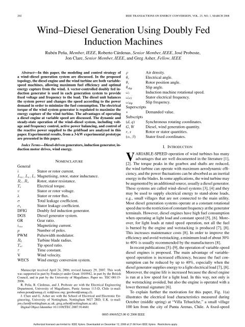
Wind–Diesel Generation Using Doubly Fed Induction Machines
Wind–Diesel Generation Using Doubly Fed Induction Machines
Wind–Diesel Generation Using Doubly Fed Induction Machines

Create successful ePaper yourself
Turn your PDF publications into a flip-book with our unique Google optimized e-Paper software.
202 IEEE TRANSACTIONS ON ENERGY CONVERSION, VOL. 23, NO. 1, MARCH 2008<br />
<strong>Wind–Diesel</strong> <strong>Generation</strong> <strong>Using</strong> <strong>Doubly</strong> <strong>Fed</strong><br />
<strong>Induction</strong> <strong>Machines</strong><br />
Rubén Peña, Member, IEEE, Roberto Cárdenas, Senior Member, IEEE, José Proboste,<br />
Jon Clare, Senior Member, IEEE, and Greg Asher, Fellow, IEEE<br />
Abstract—In this paper, the modeling and control strategy of<br />
a wind–diesel generation system are discussed. In the proposed<br />
topology, the diesel engine and the wind turbine are both variablespeed<br />
machines, allowing maximum fuel efficiency and optimal<br />
energy capture from the wind. A vector-controlled doubly fed induction<br />
generator is used in each generation system to provide<br />
fixed voltage and frequency to the load. The diesel unit balances<br />
the system power and changes the speed according to the power<br />
demand in order to minimize the fuel consumption. The electrical<br />
torque of the wind system generator is regulated to maximize the<br />
energy capture of the wind turbine. The advantages of operating<br />
a diesel engine at variable speed are discussed. The dynamic and<br />
steady-state operation of the wind–diesel system, including voltage<br />
and frequency control, active power balancing, and control of<br />
the reactive power supplied to the grid/load are analyzed in this<br />
paper. Experimental results, from a 3-kW experimental prototype<br />
are presented in this paper.<br />
Index Terms—Diesel-driven generators, induction generator, induction<br />
motor drives, wind energy.<br />
NOMENCLATURE<br />
General<br />
i Stator or rotor current.<br />
Lm ,Ls,Lr Magnetising, rotor, stator inductance.<br />
Rr ,Rs Rotor, stator resistance.<br />
Te Electrical torque.<br />
v Stator or rotor voltage.<br />
λ Stator or rotor flux.<br />
σ Total leakage coefficient.<br />
σs Stator leakage coefficient.<br />
DFIG <strong>Doubly</strong> fed induction generator.<br />
DGS Diesel generator system.<br />
GR Gear ratio.<br />
ims Magnetizing current.<br />
p Number of poles.<br />
PWM Pulsewidth modulator.<br />
Rb Turbine blade radius.<br />
Tsr Tip speed ratio.<br />
τ Time constant.<br />
V Wind velocity.<br />
WECS Wind energy conversion system.<br />
Manuscript received April 24, 2006; revised January 29, 2007. This work<br />
was supported in part by Fondecyt under Grant 1010942, in part by the British<br />
Council, and in part by the University of Magallanes. Paper no. TEC-00115-<br />
2006.<br />
R. Peña, R. Cárdenas, and J. Proboste are with the Electrical Engineering<br />
Department, University of Magallanes, Punta Arenas 113-D, Chile (e-mail:<br />
ruben.pena@umag.cl; rcd@ieee.org; jprobost@umag.cl).<br />
J. Clare and G. Asher are with the School of Electrical and Electronic Engineering,<br />
University of Nottingham, Nottingham NG7 2RD, U.K. (e-mail:<br />
jon.clare@nottingham.ac.uk; greg.asher@nottingham.ac.uk).<br />
Digital Object Identifier 10.1109/TEC.2007.914681<br />
0885-8969/$25.00 © 2008 IEEE<br />
ρ Air density.<br />
θe Electrical angle.<br />
θr Rotor position angle.<br />
θslip Slip angle.<br />
ωr <strong>Induction</strong> machine rotational speed.<br />
ωsG Stator electrical frequency.<br />
ωslip Slip frequency.<br />
Superscripts<br />
∗<br />
Subscripts<br />
Demanded value.<br />
(d, q) Synchronous rotating coordinates.<br />
G, W Diesel, wind generation quantity.<br />
r, s Rotor or stator quantities.<br />
(α, β) Stator fixed coordinates.<br />
I. INTRODUCTION<br />
VARIABLE-SPEED operation of wind turbines has many<br />
advantages that are well documented in the literature [1],<br />
[2]. The torque peaks in the gearbox and shafts are reduced,<br />
the wind turbine can operate with maximum aerodynamic efficiency,<br />
and the power fluctuations can be absorbed as an inertial<br />
energy in the blades. In some applications, the wind turbine may<br />
be augmented by an additional source, usually a diesel generator.<br />
These systems are called wind–diesel systems [3], [4] and they<br />
may be used to supply electrical energy to stand-alone loads,<br />
e.g., small villages that are not connected to the main utility.<br />
Most diesel generation systems operate at a constant rotational<br />
speed due to the restriction of constant frequency at the generator<br />
terminals. However, diesel engines have high fuel consumption<br />
when operating at light load and constant speed [5], [6]. Moreover,<br />
for light loads at rated speed operation, not all the fuel<br />
is burned by the engine and wetstacking is produced [7], [8].<br />
This increases maintenance costs [8]. In order to improve the<br />
efficiency and avoid wetstacking, a minimum load of about 30%<br />
to 40% is usually recommended by the manufacturers [8].<br />
In recent publications [5]–[9], the operation of variable-speed<br />
diesel engines is proposed. The main advantage of variablespeed<br />
operation is increased efficiency, because the fuel consumption<br />
can be reduced by up to 40%, especially when the<br />
diesel generator supplies energy to a light electrical load [7], [8].<br />
Moreover, the engine life is increased because the diesel engine<br />
is run at a low speed for a light load. In this way, not only is<br />
the wetstacking avoided, but also the engine is operated with a<br />
lower thermal signature [6].<br />
To explain further the motivation for this paper, Fig. 1(a)<br />
illustrates the electrical load characteristics measured during<br />
October (middle spring) at “Villa Tehuelche,” a small village<br />
100 km from the city of Punta Arenas, Chile. A fixed-speed<br />
Authorized licensed use limited to: IEEE Xplore. Downloaded on December 12, 2008 at 21:56 from IEEE Xplore. Restrictions apply.
PEÑA et al.: WIND–DIESEL GENERATION USING DOUBLY FED INDUCTION MACHINES 203<br />
Fig. 1. (a) Frequency distribution for the load at “Villa Tehuelches.” (b) Fuel<br />
consumption for fixed speed and variable speed operation.<br />
diesel system is used to supply electricity to the village, daily<br />
from 6:30 A.M. to 12:00 P.M. During winter, the load increases<br />
because electrical heating is used. Most of the time, the load is<br />
40% to 60% of the nominal value. The maximum load may occur<br />
few times during the year, typically, during winter. Fig. 1(b)<br />
shows the fuel consumption characteristic of the generator illustrating<br />
the saving that could be made by operating at variable<br />
speed. The overall fuel saving obtained for this month would<br />
be 22%. This saving is in addition to the other benefits outlined<br />
earlier.<br />
In general, for variable-speed operation, power electronic interfaces<br />
must be provided in order to have constant frequency<br />
and regulated voltage in the ac load. In [5], the simulation results<br />
for a variable-speed wind–diesel system, with an additional energy<br />
store, are presented illustrating the advantages of variablespeed<br />
operation. Permanent magnet machines are considered<br />
and a diode rectifier, a chopper, and an inverter are used in each<br />
generator. However, in [5], there is little discussion about load<br />
voltage regulation, performance of the system when load impacts<br />
are considered, and grid frequency control. Moreover, the<br />
control of the nonlinear diesel system is not addressed.<br />
DFIGs have long been considered as a good choice for variable<br />
speed generation systems [10]–[12]. If a DFIG is operated<br />
in a restricted speed range, the power converters are rated to<br />
only a fraction of the total system power, typically, at 30% of<br />
the machine-rated power. The wind–diesel system proposed in<br />
this paper is based on DFIGs (see Fig. 2). DFIGs are used in<br />
the variable-speed DGS and in the WECS. The machine stators<br />
are connected together to form an ac bus with fixed frequency<br />
and voltage. Three voltage source PWM converters are required<br />
for the proposed wind–diesel system. A single dc link is used to<br />
connect the DGS and WECS rotor converters. These converters<br />
are vector controlled to regulate the rotor currents in both the<br />
machines. A single vector-controlled front-end converter is used<br />
to connect the dc link to the ac bus. Some preliminary results, of<br />
the wind–diesel system, proposed in Fig. 2, are presented by the<br />
authors in [13]. However, in this publication, only simulation<br />
results are presented; the effects of inductive load disturbances<br />
are not considered. Small-signal models and control system design<br />
are not discussed. For the wind–diesel system in Fig. 2,<br />
there are at least three modes of operation. The first mode is<br />
when the wind turbine is operating at high wind speed, and the<br />
power captured by the WECS is sufficient to source the load.<br />
Fig. 2. Proposed wind–diesel system.<br />
In this case, the diesel generator is disconnected and the WECS<br />
DFIG is controlled to operate in a stand-alone mode [14]. The<br />
second mode of operation is when the wind speed is very low.<br />
In this case, the WECS is disconnected and the DGS supplies<br />
the required energy to the grid/load. Finally, the third mode<br />
of operation for the proposed wind–diesel system is when the<br />
WECS is connected to the system, but the power captured by<br />
the wind turbine is not sufficient to feed the load. Therefore, the<br />
load has to be sourced with generation from both the WECS<br />
and the DGS. The first mode of operation is not considered here<br />
since it has been discussed extensively in [14]. The second and<br />
the third modes of operation are addressed in this paper.<br />
The DGS (when connected) is always controlled to regulate<br />
the voltage and electrical frequency of the load [14]. The<br />
WECS DFIG is controlled for grid-connected operation [10],<br />
since the DGS forms a virtual grid for the WECS. Therefore,<br />
the generator is synchronized to the grid, and the vector control<br />
system is orientated in the stator flux. If the control is run<br />
on a processor other than that used for the DGS system, the<br />
stator flux is estimated from the grid voltage and stator current<br />
measurements. Otherwise, the same flux vector position<br />
used to control the DGS generator can be used to control the<br />
WECS generator [13]. The WECS DFIG electrical torque is<br />
controlled to drive the wind turbine to the point of maximum<br />
aerodynamic efficiency, optimizing the energy capture from the<br />
wind [10], [14]. When both the DGS and the WECS are sourcing<br />
the load, the power consumption has to be balanced with<br />
the total power generated by both the generators. For instance,<br />
if the energy captured from the WECS increases, the energy<br />
supplied from the DGS decreases, and the rotational speed of<br />
the diesel generator is reduced in order to save fuel and improve<br />
efficiency. On the contrary, if the energy captured from the wind<br />
turbine is reduced, then the DGS has to supply more energy<br />
into the grid, and the rotational speed of the diesel generator<br />
increases. The reactive power required by the system can be<br />
supplied from the DGS generator, the WECS generator, or from<br />
the front-end converter according to some control law, e.g., to<br />
reduce the losses and increase the efficiency of the whole generation<br />
system [11], [15]. However, the optimal control of the<br />
reactive power sourcing is outside the scope of this paper. The<br />
rest of this paper is organized as follows. In Section II, the control<br />
systems for stand-alone operation of the DGS are discussed.<br />
Fuel consumption curves obtained from a 3-kW, 220-V, 50-Hz<br />
Authorized licensed use limited to: IEEE Xplore. Downloaded on December 12, 2008 at 21:56 from IEEE Xplore. Restrictions apply.
204 IEEE TRANSACTIONS ON ENERGY CONVERSION, VOL. 23, NO. 1, MARCH 2008<br />
Fig. 3. Proposed control system for the diesel doubly fed induction machine and front-end converter.<br />
diesel generator system are presented. In Section III, the control<br />
systems for simultaneous operation of the DGS and WECS are<br />
introduced and small-signal models are analyzed. Section IV<br />
presents experimental results for the stand-alone operation of a<br />
variable speed DGS. Also, experimental results related to simultaneous<br />
operation of the WECS and DGS, operating at variable<br />
speed, are presented and discussed verifying the validity of the<br />
proposed methodology. Finally, an appraisal of the proposed<br />
wind–diesel topology is presented in the conclusion.<br />
II. MODELING AND CONTROL OF THE DIESEL SYSTEM<br />
A. Modeling and Control of the DFIG<br />
The machine equations of a DFIG in a synchronously rotating<br />
d–q reference frame, with the q-axis aligned along the stator flux<br />
vector position are given by [14]<br />
� � � �� �<br />
λdsG = LmGimsG LsG 0 idsG<br />
=<br />
0<br />
0 LsG iqsG<br />
� �� �<br />
LmG 0 idrG<br />
+<br />
(1)<br />
0 LmG iqrG<br />
� vdsG<br />
vqsG<br />
� vdrG<br />
vqrG<br />
�<br />
=<br />
�<br />
=<br />
�<br />
RsG 0<br />
��<br />
idsG<br />
0<br />
�<br />
0<br />
RsG iqsG<br />
��<br />
−ωsG λdsG<br />
+<br />
ωsG<br />
0<br />
�<br />
+ d<br />
dt<br />
�<br />
λqsG<br />
� λdsG<br />
λqsG<br />
� �� �<br />
RrG 0 idrG<br />
+<br />
0 RrG iqrG<br />
d<br />
�<br />
λdrG<br />
dt λqrG<br />
�<br />
�� �<br />
0 −ωslipG λdrG<br />
+<br />
ωslipG 0 λqrG<br />
(3)<br />
where imsG is the equivalent stator magnetizing current and<br />
ωslipG = ωsG − ωrG is the slip frequency. Aligning the d–q axis<br />
�<br />
�<br />
(2)<br />
of the reference frame on the stator flux vector gives<br />
iqrG = − LsG<br />
iqsG. (4)<br />
LmG<br />
Considering (1) and (2), the following expression is obtained<br />
for the dynamics of the magnetizing current<br />
dimsG<br />
τsG<br />
dt + imsG = idrG + 1+σsG<br />
RsG<br />
vdsG<br />
with τsG = LsG/RsG and σsG =(LsG − LmG)/LmG. The<br />
magnetizing current is controlled via the rotor excitation current<br />
idrG. The rotor current iqrG is controlled in order to follow a<br />
reference current given by (4) to force the orientation of the<br />
reference frame along the stator flux vector position. If iqrG follows<br />
the reference under the action of a fast current control loop,<br />
then the orientation of the reference frame along the stator flux<br />
vector will be correct. The vector control schematic is shown in<br />
the left-hand side of Fig. 3. The idrG and iqrG currents are regulated<br />
using the PI controllers. Compensation terms are added<br />
to the controller outputs to provide linear transfer functions in<br />
order to simplify the controller design and ensure good tracking<br />
of these currents. The slip angle is given by<br />
�<br />
θslipG = θsG − θrG = ωsG dt − θrG (6)<br />
where θrG is the DFIG rotor position. The stator flux angle θsG<br />
is obtained by the integration of the reference stator frequency<br />
ωsG =2π50 rads −1 . A diesel engine operating at variable speed<br />
regulates the speed of the generator.<br />
B. Control Strategy of the Front-End Converter<br />
The aim of the front-end or stator-side converter is to regulate<br />
the common dc link voltage E, regardless of the direction<br />
of the power flow. The converter currents are controlled with<br />
the conventional vector control approach [10] with a d–q reference<br />
frame oriented along the stator voltage vector position<br />
Authorized licensed use limited to: IEEE Xplore. Downloaded on December 12, 2008 at 21:56 from IEEE Xplore. Restrictions apply.<br />
(5)
PEÑA et al.: WIND–DIESEL GENERATION USING DOUBLY FED INDUCTION MACHINES 205<br />
Fig. 4. Diesel engine model.<br />
θv . The reference frame orientation angle can be derived from<br />
the stator flux vector position of the diesel-driven DFIG as<br />
θv = θsG + π/2. The control schematic is shown in the righthand<br />
side of Fig. 3. A PI controller is used to process the error<br />
in the dc link voltage and generate the active power component<br />
reference current. The reactive power component reference current<br />
could be set to zero, implying close-to-unity displacement<br />
factor operation, or could be the output of a reactive power<br />
controller.<br />
C. Modeling and Control of the Diesel Engine<br />
The model of the diesel engine used (see Fig. 4) is based on the<br />
previous work on fixed- and variable-speed diesel engines [6]–<br />
[9], [16]–[18], and experimental data obtained from a 3-kW<br />
diesel generator set. The dynamic of the actuator is represented<br />
by a first-order model with a time constant τ2 [16], [17] and a<br />
gain K2. The combustion system is represented as a variable<br />
gain K1, which depends on the speed and output power [16],<br />
and a dead time τ1. This dead time can be calculated as<br />
τ1 = 60st 60<br />
+ (7)<br />
2Nn 4N<br />
where st =2or four for two- or four-stroke engines, N is the<br />
speed in r/min, and n is the number of cylinders. In Fig. 4, J is<br />
the total system inertia and B is the friction coefficient. The load<br />
torque TeG is the electrical torque calculated according to [14]<br />
TeG =3 p L<br />
2<br />
2 mG<br />
imsGiqrG. (8)<br />
LsG<br />
As shown in Fig. 5, the total gain Kp = K1K2 of the diesel<br />
engine is dependent on the rotational speed of the engine and<br />
the power supplied by the DGS. Further discussion about the<br />
variation of K1 and K2 for a typical diesel generator set is<br />
presented in [16]. The fuel consumption in a diesel engine depends<br />
on the speed and torque of the machine. Fig. 6 shows<br />
the fuel consumption curves obtained experimentally from a<br />
3-kW, 220-V, 50-Hz diesel engine, for five rotational speeds.<br />
According to Fig. 6, at 20% of rated power, there is 50% of additional<br />
fuel consumption when the system is operated at rated<br />
speed instead of 0.6 pu. Fuel efficiency also decreases when<br />
the power supplied by the DGS is increased without adjusting<br />
the rotational speed. For instance, if the power supplied by the<br />
DGS is changed from 35% to 45% of the rated value, the en-<br />
Fig. 5. Variation of Kp as a function of power and rotational speed.<br />
Fig. 6. Fuel consumption versus power at various rotational speed.<br />
gine speed has to be varied from ∼0.7 to ∼0.8 pu in order to<br />
improve the system efficiency. Therefore any increase/decrease<br />
in load power should be accompanied by an increase/decrease<br />
in the rotational speed to improve the system efficiency. From<br />
the fuel consumption characteristic of Fig. 6, a continuous function<br />
for the optimal curve in the power-rotational speed plane<br />
for minimum fuel consumption can be obtained. For the diesel<br />
system tested in this paper, the relationship between the optimal<br />
rotational speed and the power supplied by the DGS is almost<br />
linear, as shown in Fig. 7. This is in broad agreement with the<br />
previous research [5]–[7]. The control scheme for the diesel<br />
engine is shown in Fig. 4. If losses in the DFIG are neglected,<br />
the power supplied by the diesel engine to the shaft is given by<br />
PeG = ωrGTeG. In order to minimize the fuel consumption, the<br />
speed demand (optimum speed) for the diesel engine is calculated<br />
by using a look-up table where the optimal power–speed<br />
curve (see Fig. 7) is implemented. The input to the look-up table<br />
is PeG, and the output is the demanded speed. The diesel speed<br />
is regulated by using a PI controller. In order to compensate the<br />
variations of Kp, a gain scheduling control system is used [16].<br />
The controller gain is a function of the speed and power and is<br />
adjusted using an additional 2-D look-up table.<br />
Authorized licensed use limited to: IEEE Xplore. Downloaded on December 12, 2008 at 21:56 from IEEE Xplore. Restrictions apply.
206 IEEE TRANSACTIONS ON ENERGY CONVERSION, VOL. 23, NO. 1, MARCH 2008<br />
using (12) and (10), for optimal power capture, the torque component<br />
current (iqrW) is regulated as<br />
i ∗ qrW = 2LsWkoptω 2 rW<br />
3pL 2 mW imsW<br />
. (13)<br />
Fig. 7. Optimal rotational speed versus power curve.<br />
III. MODELING AND CONTROL OF THE WIND TURBINE SYSTEM<br />
A. Modeling of the Wind Turbine<br />
The power captured and the mechanical torque produced by<br />
a wind turbine are given by [19], [20]<br />
Tm =0.5πρCt(Tsr,β)R 3 b V 2<br />
Pm =0.5πρCp(Tsr,β)R 2 b V 3<br />
(9)<br />
where Ct(Tsr,β) and Cp(Tsr,β) are the torque and power coefficients,<br />
respectively, β is the blade pitch angle, Tsr is the<br />
tip-speed ratio (= ωT Rb/V ), and ωT is the rotational speed of<br />
the blades. In this paper, the blade characteristic Ct(Tsr,β)reported<br />
in [21] is used. For each wind velocity, there is a point<br />
of maximum power capture when the turbine is operating at the<br />
maximum power coefficient (Cpmax) [19]. If the losses are neglected,<br />
it can be shown that, in a steady state, the wind turbine<br />
operates at an optimum power coefficient when the generator<br />
electrical torque is regulated as [20], [22]<br />
TeW = koptω 2 rW<br />
(10)<br />
where kopt is a constant that depends on the blade aerodynamic,<br />
gear box ratio, and wind turbine parameters. More information<br />
related to the control of variable-speed generators for wind<br />
energy systems is presented in [2], [10]–[12], [14], [15], [19]–<br />
[22].<br />
B. Modeling and Control of the WECS DFIG<br />
The proposed control strategy considers the generator of the<br />
WECS as a grid-connected DFIG. The grid voltage and frequency<br />
is established by the DGS system. The WECS DFIG<br />
is vector controlled with a reference frame orientated along the<br />
stator flux. The stator flux position θe is obtained as [10], [14]<br />
θe = tan −1<br />
� �<br />
λβ sW<br />
λαsW<br />
�<br />
λαsW =<br />
�<br />
λβ sW =<br />
(vαsG − RsWiαsW)dt<br />
(vβ sG − RsWiβ sW) (11)<br />
where λαsW and λβ sW are the α − β stator flux components.<br />
The electrical torque is obtained as [10]<br />
TeW =3 p L<br />
2<br />
2 With some minor modifications, the control system shown<br />
in the left-hand side of Fig. 3 can be applied to grid-connected<br />
DFIGs. In this case, the position of the synchronous reference<br />
frame is given by (11), the rotor q-axis reference current is given<br />
by (13), and the rotor d-axis reference current is set to zero, unless<br />
otherwise specified. To avoid the integrator drift produced<br />
by the dc component in the signals, the integrators of (11) are<br />
replaced by bandpass filters [10], [14]. Further information regarding<br />
vector control of grid-connected DFIGs is presented<br />
in [10].<br />
C. Control of the Proposed <strong>Wind–Diesel</strong> System<br />
This section discusses the system integration of the WECS<br />
and DGS, and the dynamic and steady-state operation of the<br />
entire system. For each DFIG, and by neglecting the losses, the<br />
relationship between the power supplied from the stator and the<br />
power supplied by the machine rotor is [23]<br />
Pr = −sPs. (14)<br />
In (14), Ps and Pr have positive values when the power is<br />
supplied from the grid to the machine stator or rotor, respectively,<br />
with s =(ωsG − ωre)/ωsG and ωre =(p/2)ωr . The net<br />
power supplied from each DFIG is<br />
PW = −(PsW + PrW) =−PsW(1 − sW )<br />
PG = −(PsG + PrG) =−PsG(1 − sG). (15)<br />
The front-end converter is used to supply electrical energy to<br />
both machine rotors. The total power supplied by the front-end<br />
converter to the machine rotors Pfe is<br />
Pfe = −(sW PsW + sGPsG). (16)<br />
From (16), it is concluded that not all the power required<br />
by the machine rotors is supplied from the grid through the<br />
front-end converter. If sW and sG have opposite signs, a part of<br />
the energy is directly supplied from the WECS DFIG rotor to<br />
the DGS DFIG rotor (or vice versa), via the common dc link.<br />
The worst case, from the viewpoint of the maximum current<br />
in the front-end converter, may occur when both generators<br />
are operating at a supersynchronous speed (i.e., sW , sG < 0).<br />
However, this case is unlikely to occur unless a high load above<br />
the nominal power of the DGS is connected to the grid. For most<br />
applications, it is considered that, by adopting similar ratings for<br />
the front-end converter and the two rotor converters will provide<br />
a satisfactory system. The total power supplied to the grid/load<br />
is<br />
PL = vdLidL + vqLiqL<br />
(17)<br />
where vdL, vqL, idL, and iqL are the d–q components of the<br />
load voltage and current. Because the stator resistance in each<br />
mW<br />
(imsWiqrW)<br />
LsW<br />
(12)<br />
machine is relatively small, vdsW ≈ vdsG ≈ vdL ≈ 0 and the<br />
load power can be obtained as PL ≈ vqLiqL. For simultaneous<br />
Authorized licensed use limited to: IEEE Xplore. Downloaded on December 12, 2008 at 21:56 from IEEE Xplore. Restrictions apply.
PEÑA et al.: WIND–DIESEL GENERATION USING DOUBLY FED INDUCTION MACHINES 207<br />
Fig. 8. Small-signal model for power component of voltages and currents.<br />
operation of the DGS and WECS, each generator supplies a<br />
fraction of the load power. From (15), the load quadrature current<br />
iqL is obtained as<br />
iqL = −(iqsW(1 − sW )+iqsG(1 − sG)). (18)<br />
Fig. 8 shows the small-signal model for the power control<br />
system of the proposed wind–diesel topology. It is assumed that<br />
the wind turbine is driven at maximum aerodynamic efficiency<br />
by regulating the electrical torque of the WECS generator via<br />
(10). The block labeled “nonlinear gain” represents the transfer<br />
function obtained by linearising (13) as<br />
∆i ∗ qrW<br />
∆ωr<br />
= 4LsWkoptωrW0<br />
3pL2 mWimsW0 . (19)<br />
The cross-coupling terms [10] between the d and q axes are<br />
neglected in Fig. 8, because they are compensated at the output<br />
of the current controller (see Fig. 3). In Fig. 8, the WECS<br />
generator is similar to a current source supplying the energy<br />
captured from the wind to the system. In order to balance the<br />
power and considering constant load operation (i.e., ∆idL ≈ 0),<br />
the relationship between the quadrature currents supplied from<br />
the WECS and DGS is obtained from (18) as<br />
∆iqsW(1 − sW )=−∆iqsG(1 − sG). (20)<br />
Therefore, a change in the power captured from the wind<br />
turbine is compensated by a change in the opposite direction<br />
for the power generated from the diesel system. Variations in<br />
the power generated by the DGS also produce changes in the<br />
rotational speed of the diesel engine that is regulated to a new<br />
operating point, minimizing the fuel consumption. If the load is<br />
relatively small compared to the energy captured by the WECS,<br />
then the pitch control of the blades [20] or the power dissipation<br />
in a dump load has to be used in order to balance the power in the<br />
system. In the proposed system, the grid voltage and frequency<br />
are regulated by the DGS generator.<br />
The grid voltage control is achieved through stator flux regulation,<br />
because the stator resistance voltage drop is negligible.<br />
Fig. 9 shows the closed loop control system used to regulate<br />
the stator flux of the DGS generator. The flux is regulated by<br />
controlling the rotor current idrG.InFig.9idL, iq , and idsW are<br />
the reactive components of the load current, front-end converter<br />
current, and the DFIG stator current, respectively. From Fig. 9, it<br />
is concluded that the load reactive power can also be supplied by<br />
Fig. 9. Small-signal model for stator flux regulation of the DGS generator.<br />
Fig. 10. Experimental system.<br />
the DGS generator. However, this is relatively slow, considering<br />
the low bandwidth of the stator flux control loop. Alternatively,<br />
the reactive power can be supplied from the front-end converter<br />
or the WECS generator.<br />
IV. EXPERIMENTAL WORK<br />
The proposed wind–diesel topology has been tested by using<br />
the experimental system shown in Fig. 10. Two DSP boards,<br />
based on the TMS320C31 processor, are used to control the<br />
whole system. The control algorithms for the emulation of the<br />
diesel engine, optimum speed tracking, vector control of the<br />
diesel-driven DFIG, and the control of the front-end converter<br />
are implemented in one of the DSP boards. A speed-controlled<br />
cage induction machine is used to emulate a 3.0-kW diesel engine<br />
with 35% transient torque overload and rated friction losses<br />
of 0.2 kW. The algorithms for the emulation of the variablespeed<br />
wind turbine, tracking of the optimal rotational speed,<br />
and vector control of the WECS DFIG are implemented in a<br />
second DSP board. The DSP boards are installed in separated<br />
host computers.<br />
Emulation of wind turbines has already been presented in [22]<br />
and [24], and is briefly discussed here. The wind turbine is emulated<br />
using a speed-controlled dc machine. To implement the<br />
emulation, wind profiles are sent from the host PC to a secondorder<br />
model of the WECS implemented in the DSP. The power<br />
coefficient curve is stored, in the DSP memory, using a look-up<br />
table. Linear interpolation is used to obtain the power coefficient<br />
Cp(Tsr,β) from the look-up table. By using a wind turbine<br />
Authorized licensed use limited to: IEEE Xplore. Downloaded on December 12, 2008 at 21:56 from IEEE Xplore. Restrictions apply.
208 IEEE TRANSACTIONS ON ENERGY CONVERSION, VOL. 23, NO. 1, MARCH 2008<br />
model and the methodology discussed in [22] and [24], the<br />
reference speed of the WECS generator (ω∗ rW ) is calculated in<br />
each sampling time (see [22]). The speed-controlled dc machine<br />
forces the DFIG speed to this value. With this emulation technique,<br />
the DFIG rotates at the same speed as that of a generator<br />
driven by a real wind turbine. A complete discussion of the<br />
emulation technique used in this paper can be found in [24]<br />
and [25].<br />
Two identical DFIGs are used for the implementation of the<br />
experimental rig. The speed range for both the machines is<br />
from 700 to 1300 r/min (rated speed 1000 r/min), ±30% of<br />
the synchronous speed, while the magnetizing current of the<br />
DGS is controlled at 7-A resulting in a 120-V stator voltage.<br />
The dc-link voltage is regulated at 530 V and a 10 µF/phase<br />
capacitor is connected to the stator to filter the high-order PWM<br />
harmonics. External DSP interfaces are used to measure the<br />
rotor position (using 10000 pulses per revolution encoders), for<br />
signal conditioning and to provide the PWM signals to the power<br />
converters. The converters switching frequency is 1 kHz and the<br />
sampling time is 0.5 ms.<br />
A. Emulation of the Diesel Engine<br />
The diesel engine emulator models both the steady state and<br />
dynamic characteristics by controlling the rotational speed of<br />
an induction machine drive (different machines were used for<br />
the emulations because of the availability of equipment in the<br />
laboratory). The rotational speed is a function of the actuator<br />
input u(s) (see Fig. 4) and the DFIG electrical torque. From<br />
Fig. 4, the rotational speed is obtained as<br />
Kpe<br />
ω(s) =<br />
−sτ1<br />
1<br />
u(s) −<br />
(1 + sτ2)(sJ + B) (sJ + B) TeG(s) (21)<br />
using (8) and the bilinear transform, (21) can be discretized to<br />
ω(z) =<br />
A =<br />
Kp [(z +1)Ts] 2 z −N t<br />
(2τ2 + Ts)(2J + BTs)(z − A)(z − C) u(z)<br />
(z +1)Ts<br />
−<br />
J(z − A) 3p<br />
2<br />
(2J − BTs)<br />
(2J + BTs)<br />
L2 mG<br />
i<br />
LsG<br />
∗ msG i ∗ qrG(z)<br />
C = (2τ2 − Ts)<br />
(2τ2 + Ts)<br />
(22)<br />
the variable delay Nt is calculated as τ1/Ts, where τ1 is obtained<br />
from (7) and Ts is the sampling time. <strong>Using</strong> (21) and<br />
(22), the emulation of the diesel engine is implemented. For<br />
each sampling time, ω(k) is calculated from (22), and is used<br />
as the demand velocity for the speed control system of the cage<br />
induction machine (see Fig. 10) i.e. the induction machine rotates<br />
at the same speed as the DGS modeled under dynamic and<br />
steady-state conditions.<br />
B. Experimental Results for the DGS<br />
Experimental results for the DGS supplying energy to a standalone<br />
load are presented in this section. The system is tested<br />
for step changes of resistive and inductive loads. Fig. 11(a)<br />
shows the speed tracking performance when step resistive loads<br />
are applied to the stator. The reference and the actual speeds<br />
Fig. 11. Control system performance for load steps. (a) Speed tracking performance.<br />
(b) Estimated fuel consumption.<br />
Fig. 12. Current response corresponding to Fig. 11. (a) Magnetizing and rotor<br />
currents. (b) Stator currents. (c) Front-end converter currents.<br />
are shown. Initially, the system is running with a 0.9 kW load<br />
at the optimum speed of 783 r/min. At t =50s, the load is<br />
increased to 1.3 kW, and correspondingly, the control strategy<br />
drives the generator to the new optimum speed of 910 r/min.<br />
A new step load is applied at t = 150 s resulting in a total<br />
load of 2.1 kW. The speed of the system increases and a new<br />
optimal speed of 1190 r/min is reached. At these loads the diesel<br />
is running, considering losses at 45%, 56%, and 85% of rated<br />
power. The load is decreased at t = 275 and 360 s. Fig. 11(b)<br />
shows the estimated fuel consumption for these load conditions,<br />
considering the experimental results of Fig. 6. Extrapolation has<br />
been used to estimate the fuel consumption outside the registered<br />
experimental data. In steady state, for 45% and 56% of rated<br />
power, the fuel saving operating at reduced speed would be 18%<br />
and 10%, respectively.<br />
Fig. 12(a) shows the magnetizing and the d–q axis rotor currents<br />
for the conditions corresponding to Fig. 11. The q-axis<br />
rotor current reflects the increase in power demand due to the<br />
load impacts. After the transient, the rotational speed and torque<br />
current settle to a new operating point. The variation in the daxis<br />
rotor current is due to the slight variation in the second<br />
Authorized licensed use limited to: IEEE Xplore. Downloaded on December 12, 2008 at 21:56 from IEEE Xplore. Restrictions apply.
PEÑA et al.: WIND–DIESEL GENERATION USING DOUBLY FED INDUCTION MACHINES 209<br />
Fig. 13. Voltages and flux corresponding to Fig. 11. (a) DC link and stator<br />
voltages. (b) d–q stator flux components.<br />
Fig. 14. Control system response for an inductive load step. (a) Speed tracking<br />
performance. (b) DC link voltage and magnetizing current.<br />
term of the right-hand side in (5). Fig. 12(b) shows the d–q axis<br />
DFIG stator current. Because the load is resistive the d-axis stator<br />
current is nearly zero and the power factor is close to unity.<br />
The q-axis stator current reflects the power changes due to the<br />
load impacts. Finally, Fig. 12(c) shows the front-end converter<br />
currents. The d–q axis front-end converter currents illustrate the<br />
operation close to unity power factor (q-axis current ≈ 0). The<br />
d-axis front-end converter current reverses when the speed is<br />
above synchronous, because power is supplied to the load from<br />
the stator and the rotor of the DFIG.<br />
Fig. 13(a) shows the dc link voltage and the rms stator voltage<br />
corresponding to the test of Fig. 11. The dc link voltage excursion<br />
is within ±10 V during these load and speed transients. The<br />
stator voltage is practically constant, and the regulation is very<br />
good because the effect of the stator resistance voltage drop is<br />
negligible. Fig. 13(b) shows the d–q stator flux components for<br />
these load and speed transients. The q-axis stator flux is close<br />
to zero, reflecting the correct orientation of the vector control<br />
system.<br />
Fig. 14 shows the operation of the system when an inductive<br />
load step is applied to the stator. Initially, the system is<br />
supplying a 1.9 kW, 0.25 kvar load, with the optimum speed<br />
control strategy enabled, and a speed of about 1128 r/min. At t<br />
≈ 1 s, a load step of about 1.65 kvar is applied. Fig. 14(a) shows<br />
Fig. 15. Current response for the test of Fig. 14. (a) Reactive power currents.<br />
(b) Active power currents.<br />
the reference and real speeds whereas Fig. 14(b) shows the dc<br />
link voltage and magnetizing current. Initially, at t ≈ 1 s, the<br />
reference speed reduces because the load impact causes a magnetizing<br />
current (and stator voltage) dip of about 30%; hence,<br />
the power supplied by the machine reduces. The settling time<br />
for the magnetizing current is about 0.8 s. After the transient,<br />
the final value for the speed (≈1214 r/min) is slightly higher<br />
than the initial speed because of the additional losses produced<br />
by the increase in the stator current.<br />
In Fig. 14, the inductive load step is disconnected at t ≈<br />
13 s. There is an overshoot in the magnetizing current (and<br />
stator voltage) of about 35%; hence, at t ≈ 13 s, the reference<br />
speed increases due to the increase in power. As the magnetizing<br />
current error goes to zero, the speed of the system settles down to<br />
about 1128 r/min. The variation on the dc link voltage is mainly<br />
produced by changes in the machine stator voltage. The dip<br />
and the overshoot of E are below 20 V. These results illustrate<br />
well-managed interactions between the controllers.<br />
Fig. 15 shows the d–q axis active and reactive power current<br />
components corresponding to the load transients of Fig. 14.<br />
The front-end converter q-axis current (iq ) is regulated at zero<br />
[see Fig. 15(a)], hence, the d-axis rotor current compensates the<br />
increase in the load reactive power. As shown in Fig. 15(b),<br />
the increase in the system losses, produced by the load step,<br />
is compensated by a small increase in the DFIG q-axis rotor<br />
current.<br />
During the load steps, the additional reactive power is supplied<br />
by the DFIG with a dynamic that is dependent on the low<br />
bandwidth of the magnetizing current control loop. The dynamic<br />
of the response can be improved if the required reactive power<br />
is supplied by the front-end converter. This is shown in Figs. 16<br />
and 17. The front-end converter reactive power is regulated in<br />
order to supply all the reactive power required by the load (i.e.,<br />
idsG ≈ 0). Fig. 16(b) shows that the dip in the magnetizing current<br />
for the reactive load step is reduced to 10% [compare with<br />
Fig. 14(b)]. However, the system losses are increased when the<br />
reactive power is supplied from the front-end converter and the<br />
speed settles to a higher value ≈1300 r/min. A dc link voltage<br />
dip of about 20 V occurs, because during transients, the angle<br />
between the stator flux and the voltage is not π/2 as assumed<br />
Authorized licensed use limited to: IEEE Xplore. Downloaded on December 12, 2008 at 21:56 from IEEE Xplore. Restrictions apply.
210 IEEE TRANSACTIONS ON ENERGY CONVERSION, VOL. 23, NO. 1, MARCH 2008<br />
Fig. 16. System performance with reactive power compensation. (a) Speed<br />
tracking. (b) Magnetizing current and dc link voltage.<br />
Fig. 17. Reactive power current components. (a) DFIG currents. (b) Front-end<br />
converter currents.<br />
by the front-end converter control system (see Fig. 3). Fig. 17<br />
shows the magnetizing currents supplied by the DFIG and frontend<br />
converter corresponding to the test of Fig. 16. The d-axis<br />
stator current is regulated at zero [see Fig. 17(a)]; hence, no<br />
change in the reactive current is seen by the machine during the<br />
inductive load impact.<br />
Fig. 18 shows steady-state results for the voltages and currents<br />
of the DFIG stator and front-end converter. These results<br />
are obtained at sub- [Fig. 18(a) and (b)] and supersynchronous<br />
speed [Fig. 18(c) and (d)]. The rotational speeds are 830 and<br />
1300 r/min, respectively. The equivalent per phase stator voltage<br />
va is also shown. The load reactive power is supplied entirely<br />
by the machine; hence; the front-end converter operates at close<br />
to unity power factor.<br />
C. Experimental Results for the DGS and WECS<br />
Assuming that the DGS is already active, connecting the<br />
WECS generator to the grid is equivalent to a step demand<br />
in the reactive power supplied by the DGS generator. As discussed<br />
in the previous section, a sudden change in the reactive<br />
power provided by the DGS DFIG may produce a relatively<br />
large variation in the magnetizing current (and stator voltage)<br />
due to the low bandwidth of the magnetizing current loop. This<br />
excursion is reduced if the front-end converter provides the reactive<br />
power. However, this reduces the maximum power current<br />
Fig. 18. Steady state operation at sub (a, b) and supersynchronous (c, d) speed.<br />
Fig. 19. WECS connection to the system. (a) DGS speed. (b) Magnetizing<br />
current and dc link voltage.<br />
available in the converter. Also, if the current supplied by the<br />
front-end converter increases, it may produce higher switching<br />
and conduction losses in this power converter. To overcome<br />
both of these difficulties, a control strategy is used in which the<br />
required reactive power is initially provided by the front-end<br />
converter. After the transient, the reference reactive power for<br />
the front-end converter is gradually reduced in order to reduce<br />
the losses and avoid variations in the stator voltage.<br />
Figs. 19 and 20 show results for connection of the WECS<br />
generator to the system. Before the connection, the rotor of the<br />
WECS DFIG is opened, and the stator is connected to the grid<br />
by using a manually operated circuit breaker. In this test, the<br />
system is sourcing a load of 1.9 kW with a 0.97 lagging power<br />
factor. Fig. 19(a) shows the speed during the transient. When<br />
the WECS is connected, the DGS speed, initially 1130 r/min,<br />
tends to increase due to the higher losses, but as the reactive<br />
power supplied by the front-end converter reduces, the losses<br />
decrease. The speed finally settles at 1215 r/min. Fig. 19(b)<br />
shows the magnetizing current and the dc link voltage. The dip<br />
and the overshoot in the magnetizing current are below 12%.<br />
The dc link voltage has a maximum overshoot of 4.5%.<br />
Authorized licensed use limited to: IEEE Xplore. Downloaded on December 12, 2008 at 21:56 from IEEE Xplore. Restrictions apply.
PEÑA et al.: WIND–DIESEL GENERATION USING DOUBLY FED INDUCTION MACHINES 211<br />
Fig. 20. Rotor and stator current corresponding to the test of Fig. 19. (a)<br />
Reactive power component. (b) Active power current components.<br />
Fig. 21. Control system response for a WECS DFIG d-axis current step. (a)<br />
Currents in the WECS. (b) Currents in the DGS.<br />
The active and reactive power current components, corresponding<br />
to the test of Fig. 19, are shown in Fig. 20. Initially,<br />
the DGS reactive stator current is zero and the total reactive current<br />
is supplied from the front-end converter [iq in Fig. 20(a)].<br />
The rotor current idrG sets the flux in the DGS machine. At<br />
t ≈ 3 s, the front-end reactive current is decreased using a slow<br />
ramp. Finally, when iq ≈ 0, the reactive power of the load is<br />
supplied by the DGS. Fig. 20(b) shows the DGS torque currents<br />
and the front-end converter active power current component<br />
(i ∗ qrW<br />
=0for this test). The variation in the DGS torque current<br />
is negligible. Therefore, considering the increase in the generator<br />
speed (see Fig. 19), the power supplied from the DGS is<br />
slightly higher than that supplied before the connection of the<br />
WECS generator.<br />
The next experimental test shows the power balance produced<br />
when a change in the active and/or reactive power generated by<br />
the WECS is balanced by an opposite variation in the active<br />
and/or reactive power generated from the DGS DFIG [see (20)<br />
and Figs. 8 and 9]. The load connected to the system is 2.0<br />
kW, and before the transient, the power factor seen from the<br />
DGS is 0.8 lagging. The speed of the WECS is controlled at<br />
800 r/min. Fig. 21(a) shows the response of the WECS DFIG<br />
rotor current controller. The q-axis rotor current is regulated at<br />
zero, and a step demand of 3-A reactive current is produced.<br />
Fig. 21(b) shows the reactive and magnetizing currents of the<br />
Fig. 22. Control system response for a WECS DFIG q-axis current step. (a)<br />
Currents in the WECS. (b) Currents in the DGS.<br />
Fig. 23. DGS speed for active and reactive power changes from the WECS.<br />
DGS DFIG when the step increase in idrW takes place. Because<br />
a part of the magnetizing current, required by the DGS generator,<br />
is provided from the WECS, the current idrG in the DGS DFIG<br />
reduces. Therefore, the power factor seen from the DGS DFIG<br />
stator increases to 0.95.<br />
The performance of the system for a step change in the torque<br />
current, iqrW, is shown in Fig. 22. The WECS d–q rotor currents,<br />
with the reactive current component set to zero, are shown<br />
in Fig. 22(a). For this test, the DGS DFIG q-axis rotor current<br />
does not change significantly, because the power balancing is<br />
produced mainly by changes in the rotational speed of the DGS<br />
and a small variation in the torque current of the DGS generator<br />
[see Figs. 22(b) and 23]. For this test, the variation in the<br />
magnetizing current is also low. The DGS speed corresponding<br />
to the tests of Figs. 21 and 22 is shown in Fig. 23. For the idrW<br />
step change, there is an increase in the DGS losses and the speed<br />
of the DGS system rises. Therefore, for this operating point the<br />
DGS DFIG is less efficient when the magnetizing current is supplied<br />
from the stator instead of the rotor. When a step increase<br />
in iqrW is applied, a part of the power required by the load is<br />
supplied from the WECS and the speed of the DGS reduces<br />
accordingly.<br />
The performance of the wind–diesel system for a step increase<br />
in wind velocity is shown in Fig. 24. A step in the wind velocity<br />
is not realistic but is a very drastic change, appropriate to verify<br />
the performance of the proposed control system. The optimum<br />
speed for the WECS corresponds to continuous operation at<br />
maximum power coefficient, and for each wind velocity, is given<br />
Authorized licensed use limited to: IEEE Xplore. Downloaded on December 12, 2008 at 21:56 from IEEE Xplore. Restrictions apply.
212 IEEE TRANSACTIONS ON ENERGY CONVERSION, VOL. 23, NO. 1, MARCH 2008<br />
Fig. 24. Speed system performance for a step increase in wind velocity.<br />
Fig. 25. Currents and voltages corresponding to the test of Fig. 24. (a) DC<br />
link voltage. (b) DGS DFIG Magnetising current. (c) DGS DFIG stator voltage.<br />
by [19]<br />
ωrW,opt = Tsr,optV<br />
Rb<br />
GR (23)<br />
where Tsr,opt is the tip speed ratio corresponding to Cpmax.<br />
Initially, a 2 kW load is connected to the ac bus and the wind<br />
velocity is 5 m/s, i.e. little power is supplied from the WECS to<br />
the load. The DGS optimum speed ≈ 1164 r/min and WECS<br />
optimum speed ≈ 650 r/min. At t ≈ 3 s, the wind velocity is<br />
increased to 10 m/s. The WECS speed increases until it reaches<br />
the new optimum speed (1300 r/min), and because the load is<br />
constant, the power supplied by the DGS reduces to balance the<br />
generated power with the power of the load. This is accompanied<br />
by a reduction of the DGS speed reaching the new optimum<br />
value of ≈ 835 r/min.<br />
The dc link voltage, DGS magnetizing current, and stator<br />
voltage, for the condition corresponding to Fig. 24, are<br />
well regulated as shown in Fig. 25(a)–(c). Even for the<br />
relatively large variation in the power generated from the<br />
WECS, the variation in the stator (grid) voltage is very small<br />
[see Fig. 25(c)].<br />
The system active power current components for the condition<br />
corresponding to Fig. 24 are shown in Fig. 26. As shown<br />
in this graphic, the DGS q-axis rotor current decreases slightly<br />
because the power reduction is mainly due to the speed variation.<br />
After the transient (t ≈ 25 s), the DGS is operating<br />
below the synchronous speed and the WECS above the synchronous<br />
speed. The net power supplied from the front-end<br />
Fig. 26. Active current components corresponding to the test of Fig. 24. (a)<br />
DGS DFIG current. (b) Front-end converter current. (c) WECS DFIG current.<br />
Fig. 27. System performance for a typical wind profile. (a) Wind profile. (b)<br />
Optimal speed and WEC real speed. (c) DGS optimal speed and real speed.<br />
converter to the rotor of both DFIGs is increased after the wind<br />
step.<br />
Therefore, as shown in Fig. 26(b), the power current id also<br />
increases.<br />
Experimental results using a wind profile are shown in Fig. 27.<br />
The wind profile used in the emulation is shown in Fig. 27(a).<br />
For this test, the WECS is initially operating with a wind velocity<br />
of 5 m/s, for t
PEÑA et al.: WIND–DIESEL GENERATION USING DOUBLY FED INDUCTION MACHINES 213<br />
Fig. 28. Control system response for the test corresponding to Fig. 27. (a) DC<br />
link voltage. (b) DGS DFIG magnetizing current. (c) Stator voltage.<br />
current, and stator voltage is very good during the whole wind<br />
profile.<br />
V. CONCLUSION<br />
In this paper, the control strategy of a wind energy system embedded<br />
in a hybrid wind–diesel variable-speed energy system<br />
has been proposed. The generation system uses two doubly fed<br />
induction machines with corresponding PWM rotor inverters<br />
connected to a common dc bus. An additional front-end converter<br />
connected to the same dc bus is employed to allow the<br />
system to operate below and above the synchronous speed. The<br />
control strategy for the diesel-driven generator allows indirect<br />
control of the stator voltage (the ac system load voltage) by<br />
regulating the stator flux magnitude via the control of the rotor<br />
current. The load frequency is also regulated by the diesel generator<br />
by imposing the rotor currents with the slip frequency. The<br />
wind energy system control strategy considers the generator as<br />
connected to a grid. The electrical torque of the WECS generator<br />
is controlled to drive the system to the rotational speed, where<br />
maximum energy capture is obtained. Depending on the load<br />
size and the power supplied by the WECS generator, the control<br />
system regulates the DGS rotational speed to minimize fuel<br />
consumption.<br />
An experimental prototype has been set up, emulating the<br />
diesel engine and the wind turbine, in order to experimentally<br />
verify the proposed control strategy. Several tests including<br />
the connection of the WECS generator to the system,<br />
load impacts, step changes in wind velocity, and operation<br />
of the WECS with a realistic wind profile, have been carried<br />
out.<br />
The experimental results have verified that the stator voltage<br />
regulation is very good. It has been experimentally demonstrated<br />
that the front-end converter can be used to supply reactive power<br />
to improve the transient performance of the magnetizing current<br />
control when a sudden reactive power load is connected to the<br />
stator. The performance obtained from the experimental tests is<br />
excellent, showing the feasibility of the proposed wind–diesel<br />
system.<br />
APPENDIX<br />
SYSTEM RATING<br />
Diesel machine (emulated): 3.0 kW, 4 cylinder, 4 stroke,<br />
τ2 =0.1 s, J =0.8 kg· m 2 . Wind turbine (emulated): 1300<br />
r/min, J =0.9 kg· m 2 , Rb =1.25 m, GR = 1.70, vrated =<br />
10 m/s. <strong>Doubly</strong> fed induction machines: 2.5 kW, 6 poles, Stator<br />
220 V delta, rotor 250 V star, Rr =0.525 Ω, Rs =0.398,<br />
Ls =0.0835 H, Lm =0.0796, Lr =0.0825. Front-end converter:<br />
C = 2600 µF , Lf =12mH. To improve current filtering<br />
30 mH is added to the rotor.<br />
REFERENCES<br />
[1] J. A. M. Bleijs, A. W. K. Chung, and J. A. Rudell, “Power smoothing<br />
and performance improvement of wind turbines with variable speed,”<br />
in Proc. 1995 17th British Wind Energy Assoc., BWEA, pp. 353–<br />
358.<br />
[2] S. M. B. Wilmshurst, “Control strategies for wind turbines,” Wind Eng.,<br />
vol. 12, pp. 236–249, Jul. 1988.<br />
[3] A. J. Rudell, J. A. M. Bleijs, L. Freris, D. G. Infield, and G. A. Smith,<br />
“A wind diesel system with variable speed flywheel storage,” Wind Eng.,<br />
vol. 17, pp. 129–145, May 1993.<br />
[4] R. Dettmer, “Revolutionary energy—A wind/diesel generator with flywheel<br />
storage,” Inst. Electr. Eng. Rev., vol. 36, pp. 149–151, Apr.<br />
1990.<br />
[5] Z. Chen and Y. Hu, “A hybrid generation system using variable speed<br />
wind turbines and diesel units,” in Proc. 2003 IEEE Ind. Electron. Soc.<br />
Annu. Meeting Conf., pp. 2729–2734.<br />
[6] L. M. Tolbert, W. A. Peterson, T. J. Theiss, and M. B. Scudiere, “Gen-sets,”<br />
IEEE Ind. Appl. Mag., vol. 9, no. 2, pp. 48–54, Mar./Apr. 2003.<br />
[7] D. Cherup, “Modelling, simulation and performance analysis of a hybrid<br />
power system for mobile medical clinic,” Ph. D. thesis, University of<br />
Kassel, Kassel, Germany, 2004.<br />
[8] J. B. Andriulli, A. E. Gates, H. D. Haynes, L. B. Klett, S. N. Matthews,<br />
E. A. Nawrocki, P. J. Otaduy, M. B. Scudiere, T. J. Theiss, J. F. Thomas,<br />
L. M. Tolbert, M. L. Yauss, and C. A. Voltz, “Advanced power generation<br />
systems for the 21st century: Market survey and recommendations for<br />
a design philosophy,” Oak Ridge National Laboratory, Oak Ridge, TN,<br />
Tech. Rep. Nov. 1999.<br />
[9] M. Kimura, H. Koharagi, S. Dodo, H. Arita, and K. Tsubouchi, “A permanent<br />
magnet synchronous generador with variable speed input for cogeneration<br />
system,” in Proc. 2001 IEEE Power Eng. Soc. Winter Meeting,<br />
pp. 1419–1424.<br />
[10] R. Peña, J. Clare, and G. Asher, “<strong>Doubly</strong>-fed induction generators using<br />
back-to-back PWM converters and its applications to variable-speed windenergy<br />
generation,” IEE Proc. Part B, vol. 153, pp. 231–241, May 1996.<br />
[11] B. Rabelo and W. Hofman, “Control of an optimized power flow in wind<br />
power plants with doubly-fed induction generators,” in Proc. 2003 IEEE<br />
Power Electron. Spec. Conf., pp. 1563–1568.<br />
[12] S. Muller, M. Deicke, and R. W. De Doncker, “<strong>Doubly</strong> fed induction<br />
generator systems for wind turbines,” IEEE Ind. Appl. Mag., vol. 8, no. 3,<br />
pp. 26–33, May/Jun. 2002.<br />
[13] R. Peña, R. Cárdenas, G. Asher, and J. Clare, “Control strategy of doubly<br />
fed induction generators for wind diesel energy system,” in Proc. 2002<br />
IEEE Ind. Electron. Soc. Annu. Meeting Conf., pp. 3297–3302.<br />
[14] R. Peña, G. Asher, and J. Clare, “A doubly fed induction generator using<br />
back to back PWM converters supplying an isolated load from a variable<br />
speed wind turbine,” in Proc. Inst. Electr. Eng. B, Sep. 1996, vol. 143,<br />
pp. 380–387.<br />
[15] B. Rabelo and W. Hofmann, “Power flow optimisation and grid integration<br />
of wind turbines with the doubly-fed induction generator,” in Proc. 2005<br />
IEEE Power Electron. Spec. Conf., pp. 2930–2936.<br />
[16] J. Jiang, “Optimal gain scheduling controller for a diesel engine,” IEEE<br />
Control Syst. Mag., vol. 14, no. 4, pp. 42–48, Aug. 1994.<br />
[17] S. Roy, O. Malik, and G. Hope, “A k-step predictive scheme for speed<br />
control of diesel driven power plants,” IEEE Trans. Ind. Appl., vol. 29,<br />
no. 2, pp. 389–396, Mar./Apr. 1993.<br />
[18] L. Guzzella and A. Amstutz, “Control of diesel engines,” IEEE Control<br />
Syst, Mag., vol. 18, no. 5, pp. 53–71, Oct. 1998.<br />
Authorized licensed use limited to: IEEE Xplore. Downloaded on December 12, 2008 at 21:56 from IEEE Xplore. Restrictions apply.
214 IEEE TRANSACTIONS ON ENERGY CONVERSION, VOL. 23, NO. 1, MARCH 2008<br />
[19] A. Miller, E. Muljadi, and D. Zinger, “A variable speed wind turbine power<br />
control,” IEEE Trans. Energy Convers., vol. 12, no. 2, pp. 181–186, Jun.<br />
1997.<br />
[20] E. Muljadi and C. P. Butterfield, “Pitch-controlled variable-speed wind<br />
turbine generation,” IEEE Trans. Ind. Appl., vol. 37, no. 1, pp. 240–246,<br />
Jan./Feb. 2006.<br />
[21] J. Craig, “Dynamics of wind generators on electric utility network,” IEEE<br />
Trans. Aerosp. Syst., vol. 12, no. 4, pp. 483–493, Jul. 1976.<br />
[22] R. Cárdenas and R. Peña, “Sensorless vector control of induction machines<br />
for variable speed wind energy applications,” IEEE Trans. Energy<br />
Convers., vol. 19, no. 1, pp. 196–205, Mar. 2004.<br />
[23] G. A. Smith and K. A. Nigim, “Wind-energy recovery by a static scherbius<br />
induction generator,” in Proc. Inst. Electr. Eng. C, Nov. 1981, vol. 128,<br />
pp. 317–324.<br />
[24] R. Cárdenas, R. Peña, G. Asher, and J. Clare, “Emulation of wind turbines<br />
and flywheels for experimental purposes,” presented at the 2001 Eur.<br />
Power Electron. Conf., Graz, Austria.<br />
[25] H. Akpolat, G. Asher, and J. Clare, “Dynamic emulation of mechanical<br />
loads using a vector-controlled induction motor-generator set,” IEEE<br />
Trans. Ind. Electron., vol. 46, no. 2, pp. 370–379, Apr. 1999.<br />
Rubén Peña (S’95–M’97) was born in Coronel,<br />
Chile. He received the Electrical Engineering degree<br />
from the University of Concepcion, Concepcion,<br />
Chile, in 1984, and the M.Sc. and Ph.D. degrees<br />
in electrical engineering from the University of<br />
Nottingham, Nottingham, U.K., in 1992 and 1996,<br />
respectively.<br />
He is currently with the Electrical Engineering Department,<br />
University of Magallanes, Punta Arenas,<br />
Chile. His current research interests include control<br />
of power electronics converters, ac drives, and renewable<br />
energy systems.<br />
Dr. Peña is a member of the Institute of Electrical and Electronic Engineers.<br />
Roberto Cárdenas (S’95–M’97–SM’07) was born<br />
in Punta Arenas, Chile. He received the Electrical Engineering<br />
degree from the University of Magallanes,<br />
Punta Arenas, Chile, in 1988, and the M.Sc. degree in<br />
electronic engineering and the Ph.D. degree in electrical<br />
engineering from the University of Nottingham,<br />
Nottingham, U.K., in 1992 and 1996, respectively.<br />
In 1989, he was a Lecturer at the University of<br />
Magallanes, where he is currently a Professor in the<br />
Electrical and Electronics Department. His current<br />
research interests include control of electrical machines,<br />
variable speed drives, and renewable energy systems.<br />
Prof. Cardenas is a member of the Institute of Electrical and Electronic<br />
Engineers. He is the author of the paper that received the Best Paper Award<br />
from the Industrial Electronics Society, for the best paper published in the IEEE<br />
TRANSACTIONS ON INDUSTRIAL ELECTRONICS during 2004.<br />
JoséProbostewas born in Puerto Natales, Chile, on<br />
March 21, 1976. He received the Electrical Engineering<br />
degree from the University of Magallanes, Punta<br />
Arenas, Chile, 2004.<br />
He is currently a Research Assistant in the Electrical<br />
Engineering Department, University of Magallanes.<br />
His current research interests include control<br />
of power electronics converters and ac drives.<br />
Jon Clare (M’90–SM’04) was born in Bristol, England.<br />
He received the B.Sc. and Ph.D. degrees in<br />
electrical engineering from the University of Bristol,<br />
Bristol, U.K., in 1979 and 1990, respectively.<br />
From 1984 to 1990, he was a Research Assistant<br />
and a Lecturer at the University of Bristol, where<br />
he was engaged in teaching and research in power<br />
electronic systems. Since 1990, he has been with<br />
the Power Electronics, <strong>Machines</strong> and Control Group,<br />
University of Nottingham, Nottingham, U.K., where<br />
he is currently a Professor in the Power Electronics<br />
and also the Head of the Research Group. His current research interests include<br />
power electronic converters and modulation strategies, variable-speed drive systems<br />
and electromagnetic compatibility.<br />
Prof. Clare is a member of the Institution of Electrical Engineers. He is also<br />
an Associate Editor for the IEEE TRANSACTIONS ON INDUSTRIAL ELECTRONICS.<br />
Greg Asher (M’98–SM’04–F’07) received the Graduate<br />
degree in electrical and electronic engineering<br />
from Bath University, Bath, U.K., in 1976, and the<br />
Ph.D. degree in bond graph structures and general<br />
dynamic systems from University of Bath, in 1979.<br />
In 1984, he was a Lecturer in Control in the School<br />
of Electrical and Electronic Engineering, University<br />
of Nottingham, Nottingham, U.K., where in 2000, he<br />
was appointed the Professor of Electrical Drives, and<br />
where he is currently the Head of the School of Electrical<br />
and Electronic Engineering. He is the author or<br />
coauthor of more than 180 research papers published in various international<br />
journals. His past research interests include motor drive systems, particularly<br />
the control of ac machines.<br />
Prof. Asher was a member of the Executive Committee of European Power<br />
Electronics (EPE) Association until 2003. He is an Associate Editor of the IEEE<br />
Industrial Electronics Society and is currently the Chair of the Power Electronics<br />
Technical Committee for the Industrial Electronics Society.<br />
Authorized licensed use limited to: IEEE Xplore. Downloaded on December 12, 2008 at 21:56 from IEEE Xplore. Restrictions apply.