Apollo 16 Hardware Manual.pdf - Universal Audio
Apollo 16 Hardware Manual.pdf - Universal Audio
Apollo 16 Hardware Manual.pdf - Universal Audio

Create successful ePaper yourself
Turn your PDF publications into a flip-book with our unique Google optimized e-Paper software.
H I GH- R ESO L U T I O N I N TER F A C E<br />
with Realtime UAD Processing<br />
<strong>Apollo</strong> <strong>16</strong> <strong>Hardware</strong> <strong>Manual</strong><br />
UA Part Number 65-00057<br />
Revision 001<br />
Customer Service & Technical Support:<br />
USA Toll-Free: +1-877-698-2834<br />
International: +1-831-440-1176<br />
www.uaudio.com
A Letter from Bill Putnam Jr.<br />
Thank you for deciding to make the <strong>Apollo</strong> <strong>16</strong> High-Resolution Interface part of your music making experience.<br />
We know that any new piece of gear requires an investment of time and money — and our goal is to make your<br />
investment pay off. The fact that we get to play a part in your creative process is what makes our efforts at UA<br />
meaningful, and we thank you for this.<br />
In many ways, <strong>Apollo</strong> and <strong>Apollo</strong> <strong>16</strong> represent the best examples of what UA has stood for over its long history;<br />
from UA’s original founding in the 1950s by my father, up through our current vision of delivering the best of<br />
both analog and digital audio technologies. For more than 50 years, UA has produced some of the most coveted<br />
pieces of analog recording equipment. More recently, we have pioneered cutting edge digital signal processing<br />
which has allowed us to offer exacting digital emulations of classic analog hardware. Our unique expertise<br />
and experience across both analog and digital have allowed us to make audio interfaces that we think are very<br />
special.<br />
Starting with high-quality analog I/O, <strong>Apollo</strong> <strong>16</strong>’s superior sonic performance serves as its foundation. This<br />
is just the beginning however, as <strong>Apollo</strong> and <strong>Apollo</strong> <strong>16</strong> are the only audio interfaces that allow you to run UAD<br />
plug-ins in real time, tracking and monitoring using any of our plug-ins. Want to monitor yourself through a<br />
Neve® console channel strip while tracking bass through a Fairchild or LA-2A compressor? Or how about tracking<br />
vocals through a Studer® tape machine with some added Lexicon® reverb?* No problem. This is something<br />
that only <strong>Apollo</strong> interfaces offer.<br />
At UA, we are dedicated to the idea that technology should ultimately serve the creative process — not be a<br />
barrier. These are the very ideals my father embodied as he invented audio equipment to solve problems in the<br />
studio. With this in mind, we have crafted <strong>Apollo</strong> <strong>16</strong>’s Console software with an “analog workflow.” The convenience<br />
of this Console workflow, along with innovations such as the Console Recall plug-in, provide ease-of-use<br />
and DAW integration for truly unique and productive experience.<br />
As you get to know <strong>Apollo</strong> <strong>16</strong> and incorporate it into your creative process, we hope that the excitement and<br />
pride that we have put into it comes through. We also hope that it earns its way into your creative process,<br />
providing you with great sound, exceptional plug-ins, and ease-of-use for years to come. Thanks.<br />
Sincerely,<br />
Bill Putnam Jr.<br />
*All trademarks are recognized as property of their respective owners. Individual UAD Powered Plug-Ins sold separately.<br />
<strong>Apollo</strong> <strong>16</strong> <strong>Hardware</strong> <strong>Manual</strong><br />
ii<br />
Welcome
Table Of Contents<br />
A Letter from Bill Putnam Jr.................................................................................................................................. ii<br />
Introduction.......................................................................................................................................................... 4<br />
What is <strong>Apollo</strong> <strong>16</strong>?.......................................................................................................................................... 4<br />
<strong>Apollo</strong> <strong>16</strong> Features.......................................................................................................................................... 5<br />
<strong>Hardware</strong> System Requirements..................................................................................................................... 6<br />
About Realtime UAD Processing..................................................................................................................... 7<br />
Combining with other UAD-2 devices............................................................................................................. 7<br />
Standalone Use.............................................................................................................................................. 7<br />
About <strong>Apollo</strong> <strong>16</strong> Documentation..................................................................................................................... 8<br />
Technical Support........................................................................................................................................... 9<br />
Front Panel.......................................................................................................................................................... 10<br />
Rear Panel.......................................................................................................................................................... 13<br />
Analog I/O.................................................................................................................................................... 13<br />
Digital I/O..................................................................................................................................................... 14<br />
Host I/O........................................................................................................................................................ <strong>16</strong><br />
Software Installation........................................................................................................................................... 17<br />
Registration & Authorization............................................................................................................................... 18<br />
Interconnections................................................................................................................................................. 19<br />
Installation Notes......................................................................................................................................... 19<br />
FireWire Basics................................................................................................................................................... 23<br />
Digital Clocking Basics....................................................................................................................................... 27<br />
Specifications..................................................................................................................................................... 29<br />
<strong>Hardware</strong> Block Diagram.................................................................................................................................... 32<br />
DB25 Wiring........................................................................................................................................................ 33<br />
Troubleshooting................................................................................................................................................... 34<br />
Additional Resources.......................................................................................................................................... 35<br />
<strong>Universal</strong> <strong>Audio</strong> Website............................................................................................................................... 35<br />
Technical Support......................................................................................................................................... 35<br />
Maintenance................................................................................................................................................ 35<br />
Voltage Selection.......................................................................................................................................... 35<br />
Warranty....................................................................................................................................................... 36<br />
Repair Service.............................................................................................................................................. 36<br />
Notices................................................................................................................................................................ 37<br />
Index................................................................................................................................................................... 39<br />
<strong>Apollo</strong> <strong>16</strong> <strong>Hardware</strong> <strong>Manual</strong><br />
iii<br />
Table Of Contents
Introduction<br />
What is <strong>Apollo</strong> <strong>16</strong>?<br />
<strong>Apollo</strong> <strong>16</strong> is a high-resolution audio interface with Realtime UAD Processing onboard that gives recording engineers<br />
a no-compromise monitoring, tracking, and mixing solution. The combination of <strong>Apollo</strong> <strong>16</strong>’s high quality<br />
converters, cue mixing, and digital signal processing help you achieve the goal of making music without the<br />
common latency and potential processor shortcomings of an all-native system. <strong>Apollo</strong> <strong>16</strong> leverages <strong>Universal</strong><br />
<strong>Audio</strong>’s expertise in DSP acceleration, UAD Powered Plug-Ins, and analog hardware design by integrating the<br />
latest cutting edge technologies in high-performance A/D-D/A conversion, DSP signal reconstruction, and host<br />
connectivity. <strong>Apollo</strong> <strong>16</strong> acts as both an audio interface with integrated DSP effects for tracking and monitoring<br />
as well as a fully integrated UAD-2 DSP accelerator for mixing and mastering.<br />
<strong>Apollo</strong> <strong>16</strong> has 4 SHARC DSPs for running UAD Powered Plug-Ins during tracking or mixing. You have an<br />
amazing sounding interface that can achieve the professional sound quality of any era in recording history by<br />
using UAD Powered Plug-Ins.<br />
<strong>Apollo</strong> <strong>16</strong> uses FireWire or Thunderbolt for computer connectivity. FireWire 800 doubles the performance of<br />
FireWire 400 and ensures the ability to use all of <strong>Apollo</strong> <strong>16</strong>’s I/O as well as its DSP processing. Thunderbolt is a<br />
high-speed data transmission protocol that provides faster throughput than FireWire. The Thunderbolt Option<br />
Card (not included) can be easily installed in <strong>Apollo</strong> <strong>16</strong>’s expansion bay allowing <strong>Apollo</strong> <strong>16</strong> to connect with<br />
Thunderbolt-enabled computers.<br />
To fully realize the low latency potential of <strong>Apollo</strong> <strong>16</strong>, the Console application is included, providing a familiar<br />
analog mixing console interface where you can load your favorite combination of Realtime UAD plug-ins. Configuring<br />
up to four unique cue mixes is quick and intuitive and you can also set up reverbs and delays (or any<br />
other UAD effects) on two auxiliary buses for comfortable tracking of live microphones and instruments.<br />
Achieving deep integration of <strong>Apollo</strong> <strong>16</strong>’s features with your favorite audio workstation software is simple<br />
thanks to the Console Recall plug-in that is compatible with VST, <strong>Audio</strong> Units, and RTAS host software. Simply<br />
place the Console Recall plug-in into any session and you have instant control over <strong>Apollo</strong> <strong>16</strong>’s monitoring and<br />
Realtime UAD plug-in wet/dry record options. A single “Sync” button on the plug-in will automatically recall the<br />
Console configuration within the DAW session without having to manage separate Console preset files, so you<br />
can be sure that the Console mix you are working with today will be accurately recalled tomorrow.<br />
Done tracking? Use <strong>Apollo</strong> <strong>16</strong> just like any other UAD-2 device for mixing in the DAW. The full UAD Powered<br />
Plug-Ins library works with <strong>Apollo</strong> <strong>16</strong>, offering the best analog emulation plug-ins available from the best<br />
companies in pro audio such as Neve, SSL, Pultec, Teletronix, Studer, Lexicon, DBX, Roland, MXR, Harrison,<br />
Empirical Labs, Manley, Ampex, and many more.* A single button in the Console lets you decide to “print” or<br />
“monitor” the Realtime UAD plug-ins – so if you want the sound of your favorite console and tape machine<br />
committed into your DAW, you can print those effects on the way in.<br />
Quite simply, <strong>Apollo</strong> <strong>16</strong> delivers the sound, feel, and flow of analog recording with all the conveniences of modern<br />
digital equipment.<br />
*All trademarks are recognized as property of their respective owners. Individual UAD Powered Plug-Ins sold separately.<br />
<strong>Apollo</strong> <strong>16</strong> <strong>Hardware</strong> <strong>Manual</strong><br />
4<br />
Introduction
<strong>Apollo</strong> <strong>16</strong> Features<br />
• Superior-sounding 18 x 20 audio interface with uncompromising UA analog design<br />
• Realtime monitoring and tracking with premium UAD Powered Plug-Ins<br />
• Additional mixing and mastering DSP horsepower for your sessions<br />
• FireWire 800 built-in; user-installable Thunderbolt Option Card (not included)<br />
<strong>Audio</strong> Interface<br />
• Sample rates up to 192 kHz at 24-bit word length<br />
• <strong>16</strong> x 18 simultaneous analog input/output channels:<br />
• <strong>16</strong> channels of analog-to-digital conversion via line inputs on dual DB25 connectors<br />
• 18 channels of digital-to-analog conversion:<br />
• <strong>16</strong> line outputs via dual DB25 connectors<br />
• Stereo monitor outputs via dual XLR connectors<br />
• Adjustable reference levels for all analog I/O (+4 dBu or -10 dBV)<br />
• Two channels of AES/EBU digital I/O with optional sample rate conversion on input<br />
• Front panel pre-fader metering of analog signal input or output levels<br />
• Two FireWire 800 ports for daisy-chaining other FireWire devices<br />
• Multiple <strong>Apollo</strong> <strong>16</strong> units can be cascaded for increased simultaneous I/O<br />
Monitoring<br />
• Independently-addressable stereo monitor outputs (in addition to <strong>16</strong> line outputs)<br />
• Digitally-controlled analog monitor outputs maintains highest fidelity<br />
• Front panel control of monitor levels and muting<br />
• Front panel pre-fader metering of monitor bus levels<br />
• Digital AES/EBU outputs can be set to mirror the analog monitor outputs<br />
UAD-2 QUAD Inside<br />
• Four SHARC DSP processors<br />
• Realtime UAD Powered Plug-Ins processing on all of <strong>Apollo</strong> <strong>16</strong>’s analog and AES/EBU inputs<br />
• Same features and functionality as other UAD-2 products when used with DAW<br />
• Can be combined with other UAD-2 devices for increased mixing DSP<br />
• Includes UAD Powered Plug-Ins “Analog Classics” bundle<br />
• Complete UAD-2 Powered Plug-Ins library is available online<br />
<strong>Apollo</strong> <strong>16</strong> <strong>Hardware</strong> <strong>Manual</strong><br />
5<br />
Introduction
Software<br />
• Console application:<br />
• Enables Realtime UAD Powered Plug-Ins processing<br />
• Controls <strong>Apollo</strong> <strong>16</strong>’s DSP mixer for realtime monitoring and/or tracking with UAD plug-ins<br />
• Four independent stereo Cue busses<br />
• Two independent stereo Auxiliary busses<br />
• Remote control of <strong>Apollo</strong> <strong>16</strong> features and functionality<br />
• Console Recall plug-in:<br />
• Saves <strong>Apollo</strong> <strong>16</strong> configurations inside DAW sessions for easy recall<br />
• Enables control of front panel parameters from within the DAW<br />
• VST, RTAS, and <strong>Audio</strong> Units plug-in formats<br />
• UAD Meter & Control Panel application:<br />
• Configures global UAD-2 and UAD Powered Plug-Ins settings and monitors system usage<br />
Other<br />
• Easily updatable firmware<br />
• 1U rack-mountable form factor<br />
• One year warranty includes parts and labor<br />
<strong>Hardware</strong> System Requirements<br />
The host computer must meet the hardware system requirements below to use <strong>Apollo</strong> <strong>16</strong>. For software system<br />
requirements, refer to the <strong>Apollo</strong> Software <strong>Manual</strong> (see “About <strong>Apollo</strong> <strong>16</strong> Documentation” on page 8).<br />
Basic audio interface I/O functionality:<br />
• Available FireWire 800 or Thunderbolt* expansion port<br />
• 2 gigabytes available disk space<br />
• Internet connection for downloading installation software**<br />
UAD-2 and Realtime UAD Powered Plug-Ins functionality:<br />
• Internet connection to download installation software** and authorize UAD plug-ins<br />
• Compatible VST, <strong>Audio</strong> Units, or RTAS plug-in host application software<br />
*Thunderbolt connections require the Thunderbolt Option Card<br />
**Software installer is not included in box<br />
<strong>Apollo</strong> <strong>16</strong> <strong>Hardware</strong> <strong>Manual</strong><br />
6<br />
Introduction
About Realtime UAD Processing<br />
<strong>Apollo</strong> <strong>16</strong> has the ability to run UAD Powered Plug-Ins in realtime. <strong>Apollo</strong> <strong>16</strong>’s groundbreaking DSP + FPGA<br />
technology enable UAD Powered Plug-Ins to run with latencies in the sub-2ms range, and multiple UAD plugins<br />
can be “stacked” in series without incurring additional latency. Realtime UAD Processing facilitates the<br />
ultimate sonic experience while monitoring and/or tracking.<br />
Note: <strong>Apollo</strong> <strong>16</strong>, like other UAD-2 devices, can only load UAD Powered Plug-Ins which are specifically<br />
designed to run on UAD-2 DSP accelerators. “Native” plug-ins cannot run on the UAD-2 DSP.<br />
Console<br />
Realtime UAD Processing is a special function that is available only within the Console application. All of<br />
<strong>Apollo</strong> <strong>16</strong>’s analog and AES/EBU inputs can perform Realtime UAD processing simultaneously, and Console<br />
inputs with (or without) Realtime UAD Processing can be routed into the DAW for recording.<br />
For complete details about Console and Realtime UAD Processing, refer to the <strong>Apollo</strong> Software <strong>Manual</strong> (see<br />
“About <strong>Apollo</strong> <strong>16</strong> Documentation” on page 8).<br />
UAD plug-ins in the DAW<br />
UAD Powered Plug-Ins can also be used within the DAW without the use of Console. UAD Powered Plug-Ins<br />
loaded within the DAW operate like other (non-UAD) plug-ins, except the processing occurs on the <strong>Apollo</strong> <strong>16</strong> DSP<br />
instead of the host computer’s processor. In this scenario, UAD plug-ins are subject to the latencies incurred by<br />
I/O buffering.<br />
For complete details about using UAD Powered Plug-Ins in the DAW, refer to the UAD System <strong>Manual</strong> (see<br />
“About <strong>Apollo</strong> <strong>16</strong> Documentation” on page 8).<br />
Combining with other UAD-2 devices<br />
<strong>Apollo</strong> <strong>16</strong> can be used simultaneously with UAD-2 cards (PCIe), UAD-2 Satellite (FireWire), and/or UAD-2 SOLO/<br />
Laptop (ExpressCard) in the same host computer system. <strong>Apollo</strong> <strong>16</strong> simply adds to the DSP availability when<br />
used with other UAD-2 devices, increasing the DSP processing power so more UAD Powered Plug-Ins can be<br />
used. Up to four UAD-2 devices can be combined in the same system.<br />
Standalone Use<br />
Although the Console application is required to unleash the full power of <strong>Apollo</strong> <strong>16</strong>, the unit can be used as a<br />
digital mixer with limited functionality without a FireWire or Thunderbolt connection to a host computer.<br />
All currently active I/O assignments, signal routings, and monitor settings are saved to internal firmware when<br />
<strong>Apollo</strong> <strong>16</strong> is powered down and persist when power is re-applied. Therefore the last-used settings are always<br />
available even when a host computer is not used.<br />
Note that UAD Powered Plug-In instantiations are not retained on power down, because the plug-in files reside<br />
on the host computer. However, if UAD plug-ins are active when <strong>Apollo</strong> <strong>16</strong>’s connection to the host system is<br />
severed, the current UAD plug-in configurations remain active for processing until <strong>Apollo</strong> <strong>16</strong> is powered down.<br />
<strong>Apollo</strong> <strong>16</strong> <strong>Hardware</strong> <strong>Manual</strong><br />
7<br />
Introduction
About <strong>Apollo</strong> <strong>16</strong> Documentation<br />
Documentation for all <strong>Apollo</strong> <strong>16</strong> components is extensive, so instructions are separated by area of functionality,<br />
as detailed below. All documentation is copied to the startup disk during UAD Powered Plug-Ins software<br />
installation (<strong>Apollo</strong> <strong>16</strong> documentation can also be downloaded from our website).<br />
Note: All manuals are in PDF format. PDF files require a free PDF reader application such as Adobe<br />
Reader (Windows) or Preview (Mac).<br />
<strong>Apollo</strong> <strong>16</strong> <strong>Hardware</strong> <strong>Manual</strong><br />
The <strong>Apollo</strong> <strong>16</strong> <strong>Hardware</strong> <strong>Manual</strong> (available in print and PDF) contains complete information about the audio<br />
interface hardware. Included are detailed descriptions for all <strong>Apollo</strong> <strong>16</strong> hardware features, control functions,<br />
and connections. Refer to this hardware manual to learn about interfacing the hardware with other devices,<br />
operating the panel controls, clocking, specifications, and related information.<br />
<strong>Apollo</strong> Software <strong>Manual</strong><br />
The <strong>Apollo</strong> Software <strong>Manual</strong> (PDF only) is the companion guide to the <strong>Apollo</strong> <strong>16</strong> <strong>Hardware</strong> <strong>Manual</strong>. It contains<br />
detailed information about how to configure and control <strong>Apollo</strong> and <strong>Apollo</strong> <strong>16</strong> software features using the<br />
Console application and Console Recall plug-in. Refer to this document to learn how to operate these essential<br />
software tools and integrate <strong>Apollo</strong> <strong>16</strong>’s audio interface functionality into the DAW environment.<br />
UAD System <strong>Manual</strong><br />
The UAD System <strong>Manual</strong> (PDF only) is the complete operation manual for <strong>Apollo</strong> <strong>16</strong>’s UAD-2 functionality and<br />
applies to the entire UAD product line. It contains detailed information about installing and configuring UAD<br />
devices, the UAD Meter & Control Panel application, how to use UAD Powered Plug-Ins within a DAW, obtaining<br />
optional plug-in licenses at the UA online store, and more. It includes everything about UAD-2 except information<br />
specific to <strong>Apollo</strong> <strong>16</strong> and individual UAD Powered Plug-In descriptions.<br />
UAD Plug-Ins <strong>Manual</strong><br />
The features and functionality of all the individual UAD Powered Plug-Ins is detailed in the UAD Plug-Ins<br />
<strong>Manual</strong> (PDF only). Refer to this document to learn about the operation, controls, and user interface of each<br />
plug-in. It does not contain any system-related or integration information.<br />
Thunderbolt Option Card<br />
All user documentation for <strong>Apollo</strong> <strong>16</strong>’s Thunderbolt Option Card is located on the Thunderbolt Support Page on<br />
our website (there is no separate manual). Please review the information on the page carefully before installing<br />
or using the device:<br />
• www.uaudio.com/support/thunderbolt<br />
<strong>Apollo</strong> <strong>16</strong> <strong>Hardware</strong> <strong>Manual</strong><br />
8<br />
Introduction
Host DAW Documentation<br />
Each host DAW application has its own particular methods for configuring audio interfaces and using plugins.<br />
Refer to the host DAW’s documentation for specific instructions about using audio interface and plug-in<br />
features within the DAW.<br />
Support Pages<br />
The latest technical information about <strong>Apollo</strong> <strong>16</strong> is posted on the <strong>Universal</strong> <strong>Audio</strong> support website. Our support<br />
pages may contain updated, late-breaking information that is not available in other publications. The URL of<br />
our support site is:<br />
• www.uaudio.com/support<br />
Technical Support<br />
<strong>Universal</strong> <strong>Audio</strong> provides free customer support to all registered <strong>Apollo</strong> <strong>16</strong> users. Our support specialists are<br />
available to assist you via email and telephone during our normal business hours, which are from 9am to 5pm,<br />
Monday through Friday, Pacific Standard Time.<br />
Telephone<br />
USA toll-free: +1-877-698-2834<br />
International: +1-831-440-1176<br />
Online Support<br />
To request online support via email, please visit our main support page at the URL below, then click the “Submit<br />
Support Ticket” button on the right side of the loaded page to create a help ticket.<br />
• www.uaudio.com/support<br />
<strong>Apollo</strong> <strong>16</strong> <strong>Hardware</strong> <strong>Manual</strong><br />
9<br />
Introduction
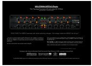
Front Panel<br />
This section describes the features and functionality of all controls and visual elements on the <strong>Apollo</strong> <strong>16</strong> front<br />
panel. Note that most front panel functions can be controlled remotely with the Console software application.<br />
1 2 3 4 5 6 7 8<br />
9<br />
MONITOR<br />
METER<br />
HOST<br />
CLOCK<br />
INT<br />
EXT<br />
METER<br />
IN<br />
OUT<br />
RATE<br />
44.1<br />
48<br />
88.2<br />
96<br />
176.4<br />
192<br />
1 2 3 4 5 6 7 8<br />
C<br />
0<br />
-3<br />
-6<br />
-9<br />
-12<br />
-15<br />
-18<br />
-21<br />
-27<br />
9 10 11 12 13 14 15 <strong>16</strong><br />
C<br />
0<br />
-3<br />
-6<br />
-9<br />
-12<br />
-15<br />
-18<br />
-21<br />
-27<br />
1 2<br />
C<br />
0<br />
-3<br />
-6<br />
-9<br />
-12<br />
-15<br />
-18<br />
-21<br />
-27<br />
METER I/O<br />
POWER<br />
OFF<br />
(1) Meter<br />
The METER button determines which signals, either input or output, are displayed by the Channel Meters (4).<br />
Push the switch to toggle the meter display state between Input and Output. The current meter state is displayed<br />
by the METER indicators (2).<br />
(2) Status Indicators<br />
These indicators display the status of the host computer connection, clock, and signal meters, as described<br />
below.<br />
Host<br />
The HOST indicator displays the status of the connection to the host computer system. The indicator is illuminated<br />
when <strong>Apollo</strong> <strong>16</strong> is connected to, and properly communicating with, the host computer system via FireWire<br />
or Thunderbolt. The indicator is off when the host computer is not detected.<br />
The <strong>Apollo</strong> <strong>16</strong> software must be properly installed and configured on the host computer to enable communication,<br />
and the HOST indicator must be illuminated to use <strong>Apollo</strong> <strong>16</strong> with all computer operations. The only time<br />
the HOST link is not required is when <strong>Apollo</strong> <strong>16</strong> is used without a computer (see “Standalone Use” on page<br />
7).<br />
Clock<br />
The CLOCK indicator displays the status of the <strong>Apollo</strong> <strong>16</strong> clock. When <strong>Apollo</strong> <strong>16</strong> is using its internal clock as the<br />
master clock source, the INT indicator is illuminated.<br />
When <strong>Apollo</strong> <strong>16</strong> is set to use an external clock as the master clock source and a valid clock signal is detected at<br />
the specified port, the EXT indicator is illuminated and white.<br />
If the EXT indicator is illuminated and red, <strong>Apollo</strong> <strong>16</strong> is configured to use an external clock but it cannot lock<br />
to the specified source, and the internal clock remains active instead. In this situation, if/when the specified<br />
external clock becomes available, <strong>Apollo</strong> <strong>16</strong> switches back to the external clock, and the EXT indicator is illuminated<br />
and white.<br />
Note: <strong>Apollo</strong> <strong>16</strong> can be configured to use its internal clock, or an external clock from the Word Clock or<br />
AES/EBU inputs. The clock setting is configured in the Interface panel of the Console Settings window;<br />
see the <strong>Apollo</strong> Software <strong>Manual</strong> for details.<br />
<strong>Apollo</strong> <strong>16</strong> <strong>Hardware</strong> <strong>Manual</strong><br />
10<br />
Front Panel
Meter<br />
The METER indicator reflects the state of the Channel Meters (4). The I/O state of the Channel Meters is<br />
switched with the METER button (1).<br />
When IN is illuminated, the Channel Meters display levels at the analog inputs. When OUT is illuminated, the<br />
Channel Meters display levels at the analog outputs.<br />
(3) Sample Rate Indicators<br />
The <strong>Apollo</strong> <strong>16</strong> sample rate is indicated in this area. The active sample rate is illuminated.<br />
(4) Channel Meters<br />
The sixteen 10-segment LED meters display the signal peak levels for analog channels 1 – <strong>16</strong>. The Channel<br />
Meters can display either the input or output levels, as determined by the METER button (1).<br />
Signal levels are displayed at the input to the A/D converters (IN mode) or the output of the D/A converters (OUT<br />
mode). The dB values of the meter LEDs are indicated between the meters for channels 4 & 5 and 12 & 13.<br />
“0” indicates a level of 0 dBFS. When digital clipping occurs, the red “C” LED illuminates. Avoid digital clipping<br />
at the channel’s A/D converter by reducing the channel’s level at its source.<br />
(5) Power Indicator (UA Logo)<br />
The <strong>Universal</strong> <strong>Audio</strong> logo illuminates when the external power supply is properly connected to an AC outlet and<br />
the power input on the rear of the unit, and the POWER switch (9) is in the up position.<br />
(6) Monitor Output Level Meters<br />
These dual 10-segment LED meters display the signal peak output levels for the monitor outputs at the output<br />
of the D/A converters. These meters are before the Monitor Level control (pre-fader) and reflect the D/A converter<br />
levels regardless of the current Monitor Level knob setting (7).<br />
The dB values of the monitor meter LEDs are indicated between the left and right channel meters. “0” indicates<br />
a level of 0 dBFS. When digital clipping occurs, the red “C” LED illuminates. Avoid clipping at the monitor D/A<br />
converters by reducing the monitor bus output level and/or the channels feeding the monitor output bus.<br />
(7) Monitor Level and Mute Knob<br />
This “endless” rotary encoder serves two functions. Rotating the knob adjusts the monitor output level, and<br />
pushing the knob mutes the monitor outputs, as described below.<br />
Monitor Level<br />
The control knob adjusts the signal level at monitor outputs on the rear panel. Although this is a digital control,<br />
the monitor volume is attenuated in the analog domain, after D/A conversion (digitally-controlled analog<br />
volume). This method provides the utmost monitoring fidelity, in contrast to digital volume controls that reduce<br />
levels by truncating the word length (“dropping bits”). The available range is from -INF dBFS (no output)<br />
to 0 dBFS.<br />
<strong>Apollo</strong> <strong>16</strong> <strong>Hardware</strong> <strong>Manual</strong><br />
11<br />
Front Panel
Monitor Mute<br />
Pushing the Monitor knob toggles the mute state of the signals at monitor outputs on the rear panel. When the<br />
monitor outputs are muted, the Monitor Level Indicator (8) is red. When the monitor outputs are not muted, the<br />
Monitor Level Indicator is green.<br />
(8) Monitor Level Indicator<br />
The signal level at the rear panel monitor outputs is displayed with the illuminated indicator ring surrounding<br />
the Monitor Level knob (7). The ring is green when the monitor outputs are active, and red when the monitor<br />
outputs are muted. This level indicator is after the Monitor Level control (post fader).<br />
Note: This feature indicates relative levels only and is not calibrated to any specific dB values.<br />
(9) Power Switch<br />
This switch applies power to <strong>Apollo</strong> <strong>16</strong>. When the unit is powered on, the <strong>Universal</strong> <strong>Audio</strong> logo is illuminated.<br />
The external power supply must be properly connected for this switch to function.<br />
As with any sound system, to avoid audio spikes in your speakers, the following steps are recommended:<br />
• Apply power to the speakers last, after all other devices (including <strong>Apollo</strong> <strong>16</strong>) are powered on.<br />
• Turn off the speakers first, before all other devices (including <strong>Apollo</strong> <strong>16</strong>) are powered off.<br />
<strong>Apollo</strong> <strong>16</strong> <strong>Hardware</strong> <strong>Manual</strong><br />
12<br />
Front Panel
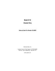
Rear Panel<br />
This section describes the features and functionality of all connectors and controls on the <strong>Apollo</strong> <strong>16</strong> rear panel.<br />
Analog I/O<br />
1 2 3<br />
AES/EBU IN<br />
MON OUT (R) 2 MON OUT (L) 1<br />
LINE OUT 9-<strong>16</strong><br />
LINE IN 9-<strong>16</strong><br />
PUSH<br />
LINE OUT 1-8 LINE IN 1-8<br />
(1) Monitor Outputs 1 & 2<br />
These balanced XLR jacks are line-level analog outputs typically used for connection to a stereo loudspeaker<br />
monitoring system. The signal levels at these outputs are controlled with the Monitor Level knob (7).<br />
The Monitor Outputs can be configured to use reference levels of +4 dBu or -10 dBV. This function is configured<br />
in the Outputs panel of the Console Settings window in the Console application.<br />
The Monitor Outputs are completely independent from the <strong>16</strong> analog line outputs. By default, the “1–2” or<br />
“Main” outputs from a DAW are routed to these outputs. Stereo panning of input signals routed to these outputs<br />
is defined within the Console and/or DAW applications.<br />
NOTE: The AES/ABU outputs can be configured to mirror the Monitor Outputs. See “(8) AES/EBU Ports”<br />
on page 15 for details.<br />
(2) Line Outputs 1 – <strong>16</strong><br />
The <strong>16</strong> analog outputs are accessed via dual female DB25 connectors. Each DB25 jack carries eight balanced<br />
line-level channel outputs using standardized Tascam wiring.<br />
The Line Outputs can be configured in adjacent pairs to use -10 dBV or +4 dBu reference levels. This function<br />
is configured in the Outputs panel of the Console Settings window in the Console application.<br />
(3) Line Inputs 1 – <strong>16</strong><br />
The <strong>16</strong> analog inputs are accessed via dual female DB25 connectors. Each DB25 jack carries eight balanced<br />
line-level channel inputs using standardized Tascam pinouts.<br />
The Line Inputs can be configured to use -10 dBV or +4 dBu reference levels. This function is configured within<br />
the input channel strips in the Console application.<br />
Note: See “DB25 Wiring” on page 33 for DB25 connector pinout diagrams.<br />
<strong>Apollo</strong> <strong>16</strong> <strong>Hardware</strong> <strong>Manual</strong><br />
13<br />
Rear Panel
(4) Power Input<br />
The included 80-watt external power supply plugs into this 4-pin locking XLR jack. <strong>Apollo</strong> <strong>16</strong> requires 12 volts<br />
DC power and draws approximately 40 watts. During typical operation when a bus-powered Thunderbolt peripheral<br />
is attached to the Thunderbolt Option Card, the system can draw up to 55 watts.<br />
To eliminate risk of circuit damage, connect only the factory-supplied power supply. Use the Power switch on<br />
the front panel to power the unit on and off.<br />
Important: Do not disconnect the power supply while <strong>Apollo</strong> <strong>16</strong> is in use, and confirm the Power<br />
switch is in the “off” position before connecting or disconnecting the power supply.<br />
Digital I/O<br />
4 5<br />
6<br />
7<br />
8<br />
1<br />
POWER<br />
OUT<br />
IN<br />
75 OHM TERM<br />
ON<br />
AES/EBU OUT<br />
AES/EBU IN<br />
MON OUT (R) 2<br />
MO<br />
PUSH<br />
PORT ( 1) PORT ( 2)<br />
WORD CLOCK<br />
FIREWIRE<br />
MADI OUT<br />
OFF<br />
MADI IN<br />
UNIVERSAL AUDIO, INC.<br />
1394 800 (1) 1394 800 (2)<br />
9<br />
10<br />
11<br />
(5) Word Clock Out<br />
This BNC connector transmits a standard (1x) word clock when <strong>Apollo</strong> <strong>16</strong> is set to use its internal clock. The<br />
clock rate sent by this port matches the current system sample rate, as specified in the Interface panel of the<br />
Console Settings window within the Console application.<br />
When <strong>Apollo</strong> <strong>16</strong> is set to use external word clock as its clock, <strong>Apollo</strong> <strong>16</strong> is a word clock slave. If the incoming<br />
external word clock is within ±0.5% of a supported sample rate (44.1 kHz, 48 kHz, 88.2 kHz, 96 kHz, 176.4 kHz,<br />
192 kHz), Word Clock Out will mirror Word Clock In with a slight phase delay (about 40ns).<br />
(6) Word Clock In<br />
<strong>Apollo</strong> <strong>16</strong>’s internal clock can be synchronized (slaved) to an external master word clock. This is accomplished<br />
by setting <strong>Apollo</strong> <strong>16</strong>’s clock source to Word Clock in the Interface panel of the Console Settings window within<br />
the Console application, connecting the external word clock’s BNC connector to <strong>Apollo</strong> <strong>16</strong>’s word clock input,<br />
and setting the external device to transmit word clock. If <strong>Apollo</strong> <strong>16</strong> is the last device in the clock chain, the<br />
Termination switch (7) should be engaged.<br />
Note: <strong>Apollo</strong> <strong>16</strong> can be synchronized to an external “1x” clock signal only. Superclock, overclocking,<br />
and subclocking are not supported.<br />
<strong>Apollo</strong> <strong>16</strong> <strong>Hardware</strong> <strong>Manual</strong><br />
14<br />
Rear Panel
(7) 75 Ohm Word Clock Termination Switch<br />
This pushbutton switch provides internal 75-ohm word clock input signal termination when required. Word<br />
clock termination is active when the switch is engaged (depressed).<br />
<strong>Apollo</strong> <strong>16</strong>’s termination switch should only be engaged when <strong>Apollo</strong> <strong>16</strong> is set to sync to external word clock and<br />
it is the last device at the receiving end of a word clock cable. For example, if <strong>Apollo</strong> <strong>16</strong> is the last “slave” unit<br />
at the end of a clock chain (when <strong>Apollo</strong> <strong>16</strong>’s word clock out port is not used), termination should be active.<br />
Note: For more information, see “Digital Clocking Basics” on page 27.<br />
(8) AES/EBU Ports<br />
The AES/EBU ports provide two channels of digital I/O with resolutions up to 192 kHz via XLR connectors. For<br />
optimum results, use only high-quality 110-ohm XLR cables specifically designed for AES/EBU digital audio.<br />
SR Convert<br />
Sample rate conversion can be enabled on the AES/EBU input. This function is set in the AES/EBU input channel<br />
strips in the Console application. When sample rate conversion is enabled and the sample rate of the<br />
incoming AES/EBU signal does not match the sample rate specified in the Console application, the AES/EBU<br />
signal is converted to match <strong>Apollo</strong> <strong>16</strong>’s sample rate.<br />
Note: When <strong>Apollo</strong> <strong>16</strong> is set to use AES/EBU as the master clock source, sample rate conversion is<br />
inactive.<br />
Mirror Monitor Outputs<br />
The AES/EBU output can be configured to mirror the Monitor outputs, for routing the stereo Monitor signal to the<br />
stereo AES/EBU input of other devices. This function is configured in the Interface panel of the Console Settings<br />
window in the Console application.<br />
<strong>Apollo</strong> <strong>16</strong> <strong>Hardware</strong> <strong>Manual</strong><br />
15<br />
Rear Panel
Host I/O<br />
Important: Connect only one <strong>Apollo</strong> <strong>16</strong> FireWire or Thunderbolt port to the host computer.<br />
(9) Expansion Bay<br />
The expansion bay is where the <strong>Universal</strong> <strong>Audio</strong> Thunderbolt Option Card is installed, providing access to all of<br />
<strong>Apollo</strong> <strong>16</strong>’s features and functionality via Thunderbolt-enabled computers.<br />
Refer to the Installation & Setup Guide included in the Thunderbolt Option Card package and our website for<br />
complete details about installation, configuration, and use of Thunderbolt with <strong>Apollo</strong> <strong>16</strong>.<br />
(10) FireWire 800 Ports<br />
<strong>Apollo</strong> <strong>16</strong> uses FireWire to communicate with the host computer system when the Thunderbolt Option Card is<br />
not in use. When <strong>Apollo</strong> <strong>16</strong> is properly connected and configured, the HOST indicator (#2 on front panel) is illuminated.<br />
<strong>Apollo</strong> <strong>16</strong> has two FireWire 800 ports. Only one port is used to connect to the host computer; the second port<br />
can be used for daisy-chaining multiple FireWire devices such as external FireWire hard drives. For more<br />
FireWire information and recommended interconnections, see ““FireWire Basics” on page 23.<br />
Note: <strong>Apollo</strong> <strong>16</strong> cannot be bus powered and it does not supply bus power from its FireWire ports to<br />
other devices.<br />
(11) MADI Optical Ports<br />
These ports use the MADI (Multichannel <strong>Audio</strong> Digital Interface) optical protocol for interconnecting with other<br />
audio hardware devices in the digital domain. MADI input and output ports are provided.<br />
The MADI ports relay the Monitor, Cue, and Auxiliary busses between multiple <strong>Apollo</strong> <strong>16</strong>’s when they are connected<br />
in a multi-unit configuration for increased simultaneous I/O. For details about MADI features with <strong>Apollo</strong><br />
<strong>16</strong>, refer to the <strong>Apollo</strong> Software <strong>Manual</strong> (see “About <strong>Apollo</strong> <strong>16</strong> Documentation” on page 8).<br />
<strong>Apollo</strong> <strong>16</strong> <strong>Hardware</strong> <strong>Manual</strong><br />
<strong>16</strong><br />
Rear Panel
Software Installation<br />
Note: Simplified procedures for software installation are below. For complete and detailed procedures,<br />
refer to the UAD System <strong>Manual</strong> (see “About <strong>Apollo</strong> <strong>16</strong> Documentation” on page 8).<br />
About UAD Software<br />
The UAD Powered Plug-Ins installer contains all the software necessary to configure and use <strong>Apollo</strong> <strong>16</strong> and UAD<br />
Powered Plug-Ins. It also installs the <strong>Apollo</strong> <strong>16</strong> hardware device drivers so the audio interface can communicate<br />
with the host computer. Therefore the UAD Powered Plug-Ins installer must be run even if you intend to use<br />
<strong>Apollo</strong> <strong>16</strong> without the use of Console or UAD Powered Plug-Ins functionality.<br />
Note: <strong>Apollo</strong> <strong>16</strong> software is not included in the package. Download it at www.uaudio.com/downloads<br />
<strong>Apollo</strong> <strong>16</strong> installation, registration, and authorization consists of four main steps:<br />
1. UAD software installation: Run the UAD Powered Plug-Ins installer downloaded from our website.<br />
2. Connect <strong>Apollo</strong> <strong>16</strong> to the host computer (and other gear): See example setups starting on page 19.<br />
3. <strong>Apollo</strong> <strong>16</strong> device registration: Add the device to your my.uaudio.com account.<br />
4. UAD plug-in authorization: Download and apply the UAD authorization file.<br />
Important: Install Software First<br />
If you are installing <strong>Apollo</strong> <strong>16</strong> software for the first time, install the software before connecting <strong>Apollo</strong> <strong>16</strong>. If you<br />
are updating to a newer version of <strong>Apollo</strong> <strong>16</strong> software or installing additional UAD devices, it is not necessary to<br />
remove the previous UAD software or hardware from the system, but you should still install the newer software<br />
before adding new UAD devices.<br />
Software System Requirements<br />
<strong>Apollo</strong> <strong>16</strong> has specific host computer software requirements in addition to the hardware requirements that are<br />
listed on page 6. Refer to the <strong>Apollo</strong> Software <strong>Manual</strong> or our website for these requirements (see “About<br />
<strong>Apollo</strong> <strong>16</strong> Documentation” on page 8).<br />
Software Updates<br />
Using the latest <strong>Apollo</strong> <strong>16</strong> software is recommended. If the software is already installed, the UAD Meter & Control<br />
Panel application has a convenient button that checks for the most recent version. For software updates,<br />
visit:<br />
• www.uaudio.com/downloads<br />
Preparation<br />
Close all open files and applications before starting the installation procedure. Specifically, make sure the<br />
Console, UAD Meter & Control Panel, and DAW applications are quit.<br />
Important: Verify the computer system date and time are set correctly before installing the software<br />
and/or launching the Console or UAD Meter & Control Panel applications for the first time.<br />
Software Installation Procedure<br />
1. Launch the UAD Powered Plug-Ins software installer downloaded from our website.<br />
2. The installer will guide you through the installation procedure.<br />
3. Connect <strong>Apollo</strong> <strong>16</strong> to the computer with a FireWire or Thunderbolt cable and power it up.<br />
4. Software installation is complete. Proceed to “Registration & Authorization” on page 18.<br />
<strong>Apollo</strong> <strong>16</strong> <strong>Hardware</strong> <strong>Manual</strong><br />
17<br />
Software Installation
Registration & Authorization<br />
Note: Simplified procedures for registration and authorization are below. For complete and detailed<br />
procedures, refer to the UAD System <strong>Manual</strong> (see “About <strong>Apollo</strong> <strong>16</strong> Documentation” on page 8).<br />
<strong>Apollo</strong> <strong>16</strong> must be registered and authorized at my.uaudio.com to unlock its UAD-2 functionality and run UAD<br />
Powered Plug-Ins. <strong>Apollo</strong> <strong>16</strong> can be used as a “regular” audio interface (bypassing all UAD-2 plug-in features)<br />
without registration and authorization. Unlicensed UAD-2 plug-ins can be used in demo mode for 14 days<br />
without authorization.<br />
Registration only needs to be completed once, however authorization must be completed each time the UAD<br />
software is updated. <strong>Apollo</strong> <strong>16</strong>, like all UAD-2 devices, stores its authorization and UAD licenses in the device<br />
itself, so the unit can be connected to a different computer without repeating the authorization process.<br />
Important: Registration and authorization can only be accomplished after successful software<br />
installation.<br />
Registration & Authorization Procedure<br />
Registration is part of the initial authorization process (it’s not a separate procedure). Note that the following<br />
steps require an Internet connection to the host computer. To authorize from a system that is not online, refer to<br />
the UAD System <strong>Manual</strong>.<br />
To register and authorize <strong>Apollo</strong> <strong>16</strong> when connected to the Internet:<br />
1. Ensure that the <strong>Apollo</strong> <strong>16</strong> software is installed and <strong>Apollo</strong> <strong>16</strong> is powered and connected to the computer<br />
via FireWire or Thunderbolt. The hardware and software systems must be communicating properly.<br />
2. Open the UAD Meter & Control Panel application. It can be accessed from the Dock (Mac) or Start Menu<br />
(Windows).<br />
3. Open the Plug-Ins panel. The panel can be accessed by typing ⌘-P (Mac) or Ctrl-P (Windows) when<br />
the application is in the foreground, or click the UAD Meter window’s Menu button then select “Plug-<br />
Ins” from the drop menu, as shown here:<br />
4. Click the “Authorize Plug-Ins…” button to begin the registration/authorization process. Our web pages<br />
will guide you; follow the instructions on screen.<br />
5. Double-click the authorization file that is automatically downloaded. The authorization is loaded into<br />
<strong>Apollo</strong> <strong>16</strong>, and after a few seconds the “Authorizations Updated Successfully” window appears.<br />
Registration and authorization is complete and <strong>Apollo</strong> <strong>16</strong> is ready for use.<br />
What Next?<br />
• See “About <strong>Apollo</strong> <strong>16</strong> Documentation” on page 8 to learn how to find the information you need.<br />
• Contact our technical support team (see page 9) if you need assistance.<br />
<strong>Apollo</strong> <strong>16</strong> <strong>Hardware</strong> <strong>Manual</strong><br />
18<br />
Registration & Authorization
Interconnections<br />
Installation Notes<br />
1. <strong>Apollo</strong> <strong>16</strong> may get hot during normal operation if it doesn’t receive adequate airflow circulation around<br />
its chassis vents. For optimum results when mounting <strong>Apollo</strong> <strong>16</strong> in a rack, we recommend leaving at<br />
least one empty rack space above the unit to allow adequate airflow for cooling.<br />
2. As with any sound system, to avoid audio spikes in your speakers, the following steps are recommended:<br />
• Apply power to the speakers last, after all other devices (including <strong>Apollo</strong> <strong>16</strong>) are powered on.<br />
• Turn off the speakers first, before all other devices (including <strong>Apollo</strong> <strong>16</strong>) are powered off.<br />
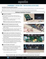
Typical Setup<br />
This diagram illustrates a basic <strong>Apollo</strong> <strong>16</strong> system. In this example, only analog devices are connected; digital<br />
I/O is not used.<br />
Key points for this example:<br />
• Either FireWire port can be used for the host computer connection<br />
• The Monitor outputs are connected to powered monitors (or an amp+speaker system)<br />
• DB25 audio snakes are used for connections to line-level audio gear<br />
• Although this example uses XLR connectors, DB25 snakes that terminate to XLR, TRS, or other DB25<br />
connectors can be used<br />
Powered<br />
Loudspeaker<br />
System<br />
POWER<br />
OUT<br />
IN<br />
75 OHM TERM<br />
ON<br />
AES/EBU OUT<br />
AES/EBU IN<br />
MON OUT (R) 2 MON OUT (L) 1<br />
LINE OUT 9-<strong>16</strong><br />
LINE IN 9-<strong>16</strong><br />
PUSH<br />
WORD CLOCK<br />
OFF<br />
PORT ( 1) PORT ( 2)<br />
FIREWIRE<br />
MADI OUT<br />
MADI IN<br />
LINE OUT 1-8 LINE IN 1-8<br />
UNIVERSAL AUDIO, INC.<br />
1394 800 (1) 1394 800 (2)<br />
FireWire<br />
800<br />
DB25 <strong>Audio</strong><br />
Snakes<br />
Computer<br />
To Outboard Gear/Console<br />
Line Level Inputs<br />
From Outboard Gear/Console<br />
Line Level Outputs<br />
<strong>Apollo</strong> <strong>16</strong> <strong>Hardware</strong> <strong>Manual</strong><br />
19<br />
Interconnections
Thunderbolt Setup<br />
This diagram illustrates how <strong>Apollo</strong> <strong>16</strong> can be connected to a host computer with the Thunderbolt Option Card.<br />
Key points for this example:<br />
• The Thunderbolt Option Card (not included) must be installed in <strong>Apollo</strong> <strong>16</strong> to connect via Thunderbolt<br />
• Either Thunderbolt port can be used for the host computer connection<br />
• A UAD-2 PCIe card in an external Thunderbolt expansion chassis is daisy-chained to second port in<br />
Thunderbolt Option Card<br />
• Monitors with AES/EBU input are connected to AES/EBU output<br />
• The “AES/EBU Mirrors Monitor 1-2” option is enabled in Console Settings so <strong>Apollo</strong> <strong>16</strong>’s front panel<br />
MONITOR knob can control the volume level of the speakers with AES/EBU input<br />
• An external FireWire 800 device is connected to <strong>Apollo</strong> <strong>16</strong> (the Thunderbolt Option Card enables <strong>Apollo</strong><br />
<strong>16</strong> to behave as a FireWire 800 hub)<br />
• Either FireWire port can be used for the external FireWire hard drive connection<br />
UAD-2 OCTO in external<br />
Thunderbolt chassis<br />
Powered<br />
Loudspeakers<br />
w/Digital<br />
Inputs<br />
POWER<br />
OUT<br />
IN<br />
75 OHM TERM<br />
ON<br />
AES/EBU OUT<br />
AES/EBU IN<br />
MON OUT (R) 2 MON OUT (L) 1<br />
LINE OUT 9-<strong>16</strong><br />
LINE IN 9-<strong>16</strong><br />
PUSH<br />
WORD CLOCK<br />
OFF<br />
PORT ( 1) PORT ( 2)<br />
FIREWIRE<br />
MADI OUT<br />
MADI IN<br />
LINE OUT 1-8 LINE IN 1-8<br />
UNIVERSAL AUDIO, INC.<br />
1394 800 (1) 1394 800 (2)<br />
Thunderbolt<br />
Computer<br />
External FW<br />
Hard Drive<br />
<strong>Audio</strong> Gear with DB25 Analog I/O<br />
<strong>Apollo</strong> <strong>16</strong> <strong>Hardware</strong> <strong>Manual</strong><br />
20<br />
Interconnections
Multi-Unit Setup – FireWire Host Connection<br />
This diagram illustrates how two <strong>Apollo</strong> <strong>16</strong> units are connected together into an aggregated interface for 32 simultaneous<br />
analog inputs and 32 simultaneous analog outputs using FireWire to connect to the host computer.<br />
Key points for this example:<br />
• One unit is designated as the “Monitor” (the master unit – where monitor connections are made)<br />
• One unit is the “Expander” (the slave unit – with higher numbered I/O)<br />
• The Monitor unit is connected to the host computer via FireWire 800<br />
(either FW port can be used for this connection)<br />
• One FireWire 800 cable must be connected between the Expander and Monitor units<br />
(either FireWire port can be used for this connection)<br />
• One MADI cable must be connected from the MADI OUT of Expander unit to the MADI IN of Monitor unit<br />
Expander Unit<br />
POWER<br />
OUT<br />
IN<br />
75 OHM TERM<br />
ON<br />
AES/EBU OUT<br />
AES/EBU IN<br />
MON OUT (R) 2 MON OUT (L) 1<br />
LINE OUT 9-<strong>16</strong><br />
LINE IN 9-<strong>16</strong><br />
PUSH<br />
WORD CLOCK<br />
OFF<br />
PORT ( 1) PORT ( 2)<br />
FIREWIRE<br />
MADI OUT<br />
MADI IN<br />
LINE OUT 1-8 LINE IN 1-8<br />
UNIVERSAL AUDIO, INC.<br />
1394 800 (1) 1394 800 (2)<br />
Monitor Unit<br />
POWER<br />
OUT<br />
IN<br />
75 OHM TERM<br />
ON<br />
AES/EBU OUT<br />
AES/EBU IN<br />
MON OUT (R) 2 MON OUT (L) 1<br />
LINE OUT 9-<strong>16</strong><br />
LINE IN 9-<strong>16</strong><br />
PUSH<br />
WORD CLOCK<br />
OFF<br />
PORT ( 1) PORT ( 2)<br />
FIREWIRE<br />
MADI OUT<br />
MADI IN<br />
LINE OUT 1-8 LINE IN 1-8<br />
UNIVERSAL AUDIO, INC.<br />
1394 800 (1) 1394 800 (2)<br />
FireWire 800<br />
Computer<br />
Connect speakers<br />
to Monitor unit<br />
<strong>Apollo</strong> <strong>16</strong> <strong>Hardware</strong> <strong>Manual</strong><br />
21<br />
Interconnections
Multi-Unit Setup – Thunderbolt Host Connection<br />
This diagram illustrates how two <strong>Apollo</strong> <strong>16</strong> units are connected together into an aggregated interface for 32<br />
simultaneous analog inputs and 32 simultaneous analog outputs.<br />
Key points for this example:<br />
• Both units require the Thunderbolt Option Card to be installed<br />
• One unit is designated as the “Monitor” (the master unit – where monitor connections are made)<br />
• One unit is the “Expander” (the slave unit – with higher numbered I/O)<br />
• The Monitor unit must be connected to the host computer via the Thunderbolt Option Card<br />
(either Thunderbolt port can be used)<br />
• One Thunderbolt cable must be connected between the Expander and Monitor units<br />
(either Thunderbolt port can be used)<br />
• One FireWire 800 cable must be connected between the Expander and Monitor units<br />
(either FireWire port can be used)<br />
• One MADI cable must be connected from the MADI OUT of Expander unit to the MADI IN of Monitor unit<br />
Expander Unit<br />
POWER<br />
OUT<br />
IN<br />
75 OHM TERM<br />
ON<br />
AES/EBU OUT<br />
AES/EBU IN<br />
MON OUT (R) 2 MON OUT (L) 1<br />
LINE OUT 9-<strong>16</strong><br />
LINE IN 9-<strong>16</strong><br />
PUSH<br />
WORD CLOCK<br />
OFF<br />
PORT ( 1) PORT ( 2)<br />
FIREWIRE<br />
MADI OUT<br />
MADI IN<br />
LINE OUT 1-8 LINE IN 1-8<br />
UNIVERSAL AUDIO, INC.<br />
1394 800 (1) 1394 800 (2)<br />
Monitor Unit<br />
POWER<br />
OUT<br />
IN<br />
75 OHM TERM<br />
ON<br />
AES/EBU OUT<br />
AES/EBU IN<br />
MON OUT (R) 2 MON OUT (L) 1<br />
LINE OUT 9-<strong>16</strong><br />
LINE IN 9-<strong>16</strong><br />
PUSH<br />
WORD CLOCK<br />
OFF<br />
PORT ( 1) PORT ( 2)<br />
FIREWIRE<br />
MADI OUT<br />
MADI IN<br />
LINE OUT 1-8 LINE IN 1-8<br />
UNIVERSAL AUDIO, INC.<br />
1394 800 (1) 1394 800 (2)<br />
Thunderbolt<br />
Computer<br />
Connect speakers<br />
to Monitor unit<br />
<strong>Apollo</strong> <strong>16</strong> <strong>Hardware</strong> <strong>Manual</strong><br />
22<br />
Interconnections
FireWire Basics<br />
FireWire (also known as “IEEE 1394” and “i.Link”) is a high-speed serial data interconnection protocol that is<br />
used to transfer digital data between devices. FireWire is commonly used to interconnect computer systems to<br />
hard drives, audio interfaces, and digital camcorders. A complete discussion of FireWire is beyond the scope of<br />
this manual, but some of the main points and how they apply to <strong>Apollo</strong> <strong>16</strong> are covered below.<br />
Important: On Windows systems, <strong>Apollo</strong> <strong>16</strong> requires a qualified PCIe-to-FireWire adapter card. For<br />
details, see www.uaudio.com/support/apollo<br />
FireWire vs. USB<br />
FireWire is considered superior to USB for audio purposes because it does not rely on the host processor to<br />
manage low-level data housekeeping (among other reasons). FireWire typically outperforms USB at the same<br />
rated speeds.<br />
FireWire Bus<br />
FireWire devices are connected to a FireWire “bus” which is comprised of all devices in the serial data stream.<br />
The FireWire specification supports up to 63 devices per FireWire bus.<br />
Many FireWire devices and host computers have more than one FireWire connector, but these connectors almost<br />
always attach to the same FireWire bus (most computers do not have more than one FireWire bus). It is possible<br />
to add another FireWire bus to a computer, typically by adding a PCIe-to-FireWire or ExpressCard-to-FireWire<br />
adapter card.<br />
Bus Power<br />
Some FireWire devices can be “bus powered” which means the device derives its operating electricity from the<br />
FireWire bus itself without a power supply of its own. <strong>Apollo</strong> <strong>16</strong> cannot be bus powered and it does not supply<br />
bus power from its FireWire ports to other devices.<br />
Powering Down<br />
Powering down or disconnecting <strong>Apollo</strong> <strong>16</strong> when UAD plug-ins are loaded could cause session data loss and/<br />
or unpredictable behavior. Quit all UAD host applications (DAW, Console, UAD Meter & Control Panel) before<br />
disconnecting <strong>Apollo</strong>.<br />
FireWire 800 vs. FireWire 400<br />
The most common FireWire devices are available in two speeds: FireWire 400 (IEEE 1394a), which supports<br />
transfer speeds up to 400 megabits per second, and FireWire 800 (IEEE 1394b), which supports up to 800<br />
megabits per second. It’s usually possible to determine the speed of the FireWire device by the type of FireWire<br />
connector it uses. <strong>Apollo</strong> <strong>16</strong> is a FireWire 800 device.<br />
<strong>Apollo</strong> <strong>16</strong> <strong>Hardware</strong> <strong>Manual</strong><br />
23<br />
FireWire Basics
METER<br />
HOST RATE<br />
CLOCK 44.1<br />
INT 48<br />
EXT 88.2<br />
METER 96<br />
IN 176.4<br />
OUT 192<br />
1 2 3 4 5 6 7 8<br />
C<br />
0<br />
-3<br />
-6<br />
-9<br />
-12<br />
-15<br />
-18<br />
-21<br />
-27<br />
9 10 11 12 13 14 15 <strong>16</strong><br />
C<br />
0<br />
-3<br />
-6<br />
-9<br />
-12<br />
-15<br />
-18<br />
-21<br />
-27<br />
METER<br />
HOST RATE<br />
CLOCK 44.1<br />
INT 48<br />
EXT 88.2<br />
1 2<br />
C<br />
0<br />
-3<br />
-6<br />
-9<br />
-12<br />
-15<br />
-18<br />
-21<br />
-27<br />
1 2 3 4 5 6 7 8<br />
C<br />
0<br />
-3<br />
-6<br />
-9<br />
MONITOR<br />
METER<br />
POWER<br />
METER I/O<br />
OFF<br />
HOST RATE<br />
CLOCK 44.1<br />
INT 48<br />
EXT 88.2<br />
METER 96<br />
IN 176.4<br />
OUT 192<br />
9 10 11 12 13 14 15 <strong>16</strong><br />
C<br />
0<br />
-3<br />
-6<br />
-9<br />
1 2 3 4 5 6 7 8<br />
C<br />
0<br />
-3<br />
-6<br />
-9<br />
-12<br />
-15<br />
-18<br />
-21<br />
-27<br />
1 2<br />
C<br />
0<br />
-3<br />
-6<br />
-9<br />
9 10 11 12 13 14 15 <strong>16</strong><br />
C<br />
0<br />
-3<br />
-6<br />
-9<br />
-12<br />
-15<br />
-18<br />
-21<br />
-27<br />
MONITOR<br />
POWER<br />
METER I/O<br />
1 2<br />
C<br />
0<br />
-3<br />
-6<br />
-9<br />
-12<br />
-15<br />
-18<br />
-21<br />
-27<br />
MONITOR<br />
METER I/O<br />
POWER<br />
OFF<br />
FireWire Connectors<br />
FireWire 800 and FireWire 400 devices use different connectors, as illustrated below. This helps to differentiate<br />
between the two device speeds (the connectors are not interchangeable).<br />
FW 800 (9-pin) FW 400 (6-pin) FW 400 (4-pin)<br />
FireWire 400 connectors<br />
FireWire 400 devices typically have two types of connector: 4-pin and 6-pin. The small 4-pin FireWire 400<br />
connector is common on digital camcorders and Windows notebook computers. The 6-pin connector is more<br />
common with hard drives and audio devices.<br />
FireWire 800 connector<br />
FireWire 800 devices use a 9-pin connector. 9-pin to 6-pin FireWire adapter cables are available to connect<br />
FireWire 800 devices to a FireWire 400 bus (with half the bandwidth).<br />
<strong>Apollo</strong> <strong>16</strong> has two FireWire 800 ports to facilitate easy daisy chaining with other FireWire devices.<br />
FireWire Repeaters and Chains<br />
FireWire devices can be connected to each other serially in a “daisy chain,” connected to a central device such<br />
as a computer with multiple FireWire ports or a peripheral FireWire repeater, or any combination of the two in a<br />
“tree chain” topology.<br />
<strong>Apollo</strong> <strong>16</strong> can function as a FireWire repeater, by using the unused port on the unit to connect other FireWire<br />
devices. Note that <strong>Apollo</strong> <strong>16</strong> does not supply FireWire bus power to downstream devices.<br />
The examples below show a few of the many interconnection possibilities using daisy chains and repeaters.<br />
Computer <strong>Apollo</strong> <strong>16</strong><br />
Hard Drive<br />
FireWire bus connections via daisy chain<br />
Computer<br />
FW Repeater<br />
<strong>Apollo</strong> <strong>16</strong><br />
Hard Drive<br />
FireWire bus connections via repeater<br />
Hard Drive<br />
<strong>Apollo</strong> <strong>16</strong> <strong>Hardware</strong> <strong>Manual</strong><br />
Computer<br />
FW Repeater<br />
24<br />
<strong>Apollo</strong> <strong>16</strong><br />
FireWire Basics<br />
Hard Drive
METER<br />
METER<br />
METER<br />
HOST<br />
CLOCK<br />
INT<br />
EXT<br />
METER<br />
IN<br />
OUT<br />
RATE<br />
44.1<br />
48<br />
88.2<br />
96<br />
176.4<br />
192<br />
HOST RATE<br />
CLOCK 44.1<br />
INT 48<br />
EXT 88.2<br />
METER 96<br />
IN 176.4<br />
OUT 192<br />
HOST RATE<br />
CLOCK 44.1<br />
INT 48<br />
EXT 88.2<br />
METER 96<br />
IN 176.4<br />
OUT 192<br />
1 2 3 4 5 6 7 8<br />
C<br />
0<br />
-3<br />
-6<br />
-9<br />
-12<br />
-15<br />
-18<br />
-21<br />
-27<br />
1 2 3 4 5 6 7 8<br />
C<br />
0<br />
-3<br />
-6<br />
-9<br />
-12<br />
-15<br />
-18<br />
-21<br />
-27<br />
1 2 3 4 5 6 7 8<br />
C<br />
0<br />
-3<br />
-6<br />
-9<br />
-12<br />
-15<br />
-18<br />
-21<br />
-27<br />
METER<br />
9 10 11 12 13 14 15 <strong>16</strong><br />
C<br />
0<br />
-3<br />
-6<br />
-9<br />
-12<br />
-15<br />
-18<br />
-21<br />
-27<br />
METER<br />
METER<br />
9 10 11 12 13 14 15 <strong>16</strong><br />
C<br />
0<br />
-3<br />
-6<br />
-9<br />
-12<br />
-15<br />
-18<br />
-21<br />
-27<br />
9 10 11 12 13 14 15 <strong>16</strong><br />
C<br />
0<br />
-3<br />
-6<br />
-9<br />
-12<br />
-15<br />
-18<br />
-21<br />
-27<br />
HOST RATE<br />
CLOCK 44.1<br />
INT 48<br />
EXT 88.2<br />
METER 96<br />
IN 176.4<br />
OUT 192<br />
HOST<br />
CLOCK<br />
INT<br />
EXT<br />
METER<br />
IN<br />
OUT<br />
RATE<br />
44.1<br />
48<br />
88.2<br />
96<br />
176.4<br />
192<br />
HOST RATE<br />
CLOCK 44.1<br />
INT 48<br />
EXT 88.2<br />
METER 96<br />
IN 176.4<br />
OUT 192<br />
METER<br />
1 2 3 4 5 6 7 8<br />
C<br />
0<br />
-3<br />
-6<br />
-9<br />
-12<br />
-15<br />
-18<br />
-21<br />
-27<br />
METER<br />
HOST RATE<br />
CLOCK 44.1<br />
INT 48<br />
EXT 88.2<br />
METER 96<br />
IN 176.4<br />
OUT 192<br />
METER<br />
1 2 3 4 5 6 7 8<br />
C<br />
0<br />
-3<br />
-6<br />
-9<br />
-12<br />
-15<br />
-18<br />
-21<br />
-27<br />
1 2<br />
C HOST<br />
0 CLOCK<br />
METER -3<br />
-6 INT<br />
-9<br />
EXT<br />
-12<br />
-15 METER<br />
-18<br />
IN<br />
-21<br />
-27 OUT<br />
1 2<br />
C<br />
0<br />
-3<br />
-6<br />
-9<br />
-12<br />
-15<br />
-18<br />
-21<br />
-27<br />
METER<br />
1 2 3 4 5 6 7 8<br />
C<br />
0<br />
-3<br />
-6<br />
-9<br />
-12<br />
-15<br />
-18<br />
-21<br />
-27<br />
METER<br />
1 2<br />
C<br />
0<br />
-3<br />
-6<br />
-9<br />
-12<br />
-15<br />
-18<br />
-21<br />
-27<br />
HOST RATE<br />
CLOCK 44.1<br />
INT 48<br />
EXT 88.2<br />
METER 96<br />
IN 176.4<br />
OUT 192<br />
HOST RATE<br />
CLOCK 44.1<br />
INT 48<br />
EXT 88.2<br />
METER 96<br />
IN 176.4<br />
OUT 192<br />
HOST RATE<br />
CLOCK 44.1<br />
INT 48<br />
EXT 88.2<br />
METER 96<br />
IN 176.4<br />
OUT 192<br />
9 10 11 12 13 14 15 <strong>16</strong><br />
C<br />
0<br />
-3<br />
-6<br />
-9<br />
-12<br />
-15<br />
-18<br />
-21<br />
-27<br />
9 10 11 12 13 14 15 <strong>16</strong><br />
C<br />
0<br />
-3<br />
-6<br />
-9<br />
-12<br />
-15<br />
-18<br />
-21<br />
-27<br />
1 2 3 4 5 6 7 8<br />
C<br />
0<br />
-3<br />
-6<br />
-9<br />
-12<br />
-15<br />
-18<br />
-21<br />
-27<br />
MONITOR<br />
1 2 3 4 5 6 7 8<br />
RATE<br />
C<br />
POWER<br />
44.1<br />
0<br />
-3<br />
48<br />
-6<br />
88.2<br />
-9METER I/O<br />
-12<br />
96<br />
-15<br />
176.4<br />
-18<br />
OFF<br />
-21<br />
192<br />
-27<br />
MONITOR<br />
MONITOR<br />
HOST RATE<br />
CLOCK 44.1<br />
INT 48<br />
EXT 88.2<br />
METER 96<br />
IN 176.4<br />
OUT 192<br />
9 10 11 12 13 14 15 <strong>16</strong><br />
C<br />
0<br />
-3<br />
-6<br />
-9<br />
-12<br />
-15<br />
-18<br />
-21<br />
-27<br />
1 2 3 4 5 6 7 8<br />
C<br />
0<br />
-3<br />
-6<br />
-9<br />
-12<br />
-15<br />
-18<br />
-21<br />
-27<br />
POWER<br />
METER I/O<br />
OFF<br />
POWER<br />
METER I/O<br />
OFF<br />
1 2 3 4 5 6 7 8<br />
C<br />
0<br />
-3<br />
-6<br />
-9<br />
-12<br />
-15<br />
-18<br />
-21<br />
-27<br />
1 2 3 4 5 6 7 8<br />
C<br />
0<br />
-3<br />
-6<br />
-9<br />
-12<br />
-15<br />
-18<br />
-21<br />
-27<br />
1 2 3 4 5 6 7 8<br />
C<br />
0<br />
-3<br />
-6<br />
-9<br />
-12<br />
-15<br />
-18<br />
-21<br />
-27<br />
1 2<br />
C<br />
0<br />
-3<br />
-6<br />
-9<br />
-12<br />
-15<br />
-18<br />
-21<br />
-27<br />
9 10 11 12 13 14 15 <strong>16</strong><br />
C<br />
0<br />
-3<br />
-6<br />
-9<br />
-12<br />
-15<br />
-18<br />
-21<br />
-27<br />
HOST RATE<br />
CLOCK 44.1<br />
METER<br />
INT 48<br />
EXT 88.2<br />
METER 96<br />
IN 176.4<br />
OUT 192<br />
9 10 11 12 13 14 15 <strong>16</strong><br />
C<br />
0<br />
-3<br />
-6<br />
-9<br />
-12<br />
-15<br />
-18<br />
-21<br />
-27<br />
9 10 11 12 13 14 15 <strong>16</strong><br />
C<br />
0<br />
-3<br />
-6<br />
-9<br />
-12<br />
-15<br />
-18<br />
-21<br />
-27<br />
1 2<br />
C<br />
0<br />
-3<br />
-6<br />
-9<br />
-12<br />
-15<br />
-18<br />
-21<br />
-27<br />
9 10 11 12 13 14 15 <strong>16</strong><br />
C<br />
0<br />
-3<br />
-6<br />
-9<br />
-12<br />
-15<br />
-18<br />
-21<br />
-27<br />
METER<br />
HOST RATE<br />
CLOCK 44.1<br />
INT 48<br />
EXT 88.2<br />
METER 96<br />
IN 176.4<br />
OUT 192<br />
MONITOR<br />
9 10 11 12 13 14 15 <strong>16</strong><br />
C<br />
0<br />
-3<br />
-6<br />
-9<br />
-12<br />
-15<br />
-18<br />
-21<br />
-27<br />
1 2<br />
C<br />
0<br />
-3<br />
-6<br />
-9<br />
-12<br />
-15<br />
-18<br />
-21<br />
-27<br />
9 10 11 12 13 14 15 <strong>16</strong><br />
C<br />
0<br />
-3<br />
-6<br />
-9<br />
-12<br />
-15<br />
-18<br />
-21<br />
-27<br />
MONITOR<br />
MONITOR<br />
1 2<br />
C<br />
0<br />
-3<br />
-6<br />
-9<br />
-12<br />
-15<br />
-18<br />
-21<br />
-27<br />
1 2<br />
C<br />
0<br />
-3<br />
-6<br />
-9<br />
-12<br />
-15<br />
-18<br />
-21<br />
-27<br />
1 2<br />
C<br />
0<br />
-3<br />
-6<br />
-9<br />
-12<br />
-15<br />
-18<br />
-21<br />
-27<br />
1 2 3 4 5 6 7 8<br />
C<br />
0<br />
-3<br />
-6<br />
-9<br />
-12<br />
-15<br />
-18<br />
-21<br />
-27 1 2<br />
C<br />
0<br />
-3<br />
-6<br />
-9<br />
-12<br />
-15<br />
-18<br />
-21<br />
-27<br />
1 2 3 4 5 6 7 8<br />
C<br />
0<br />
-3<br />
-6<br />
-9<br />
-12<br />
-15<br />
-18<br />
-21<br />
-27<br />
POWER<br />
METER I/O<br />
OFF<br />
POWER<br />
METER I/O<br />
OFF<br />
MONITOR<br />
POWER<br />
METER I/O<br />
OFF<br />
MONITOR<br />
MONITOR<br />
1 2<br />
C<br />
0<br />
-3<br />
-6<br />
-9<br />
-12<br />
-15<br />
-18<br />
-21<br />
-27<br />
1 2<br />
C<br />
0<br />
-3<br />
-6<br />
-9<br />
-12<br />
-15<br />
-18<br />
-21<br />
-27<br />
POWER<br />
METER I/O<br />
OFF<br />
9 10 11 12 13 14 15 <strong>16</strong><br />
C<br />
0<br />
-3<br />
-6<br />
-9<br />
-12<br />
-15<br />
-18<br />
MONITOR<br />
-21<br />
-27<br />
MONITOR<br />
POWER<br />
METER I/O<br />
OFF<br />
METER I/O<br />
POWER<br />
OFF<br />
9 10 11 12 13 14 15 <strong>16</strong><br />
C<br />
0<br />
-3<br />
-6<br />
-9<br />
-12<br />
-15<br />
-18<br />
-21<br />
-27<br />
MONITOR<br />
POWER<br />
METER I/O<br />
OFF<br />
POWER<br />
METER I/O<br />
OFF<br />
POWER<br />
METER I/O<br />
OFF<br />
1 2<br />
C<br />
0<br />
-3<br />
-6<br />
-9<br />
-12<br />
-15<br />
-18<br />
-21<br />
-27<br />
1 2<br />
C<br />
0<br />
-3<br />
-6<br />
-9<br />
-12<br />
-15<br />
-18<br />
-21<br />
-27<br />
MONITOR<br />
MONITOR<br />
POWER<br />
METER I/O<br />
OFF<br />
POWER<br />
METER I/O<br />
OFF<br />
Computer<br />
Computer<br />
FW Repeater<br />
FW Repeater<br />
Computer<br />
FireWire bus connections via repeater<br />
FireWire bus connections via daisy chain<br />
FW Repeater<br />
Hard Drive<br />
<strong>Apollo</strong> <strong>16</strong><br />
<strong>Apollo</strong> <strong>16</strong><br />
<strong>Apollo</strong> <strong>16</strong><br />
Hard Drive<br />
FireWire bus connections<br />
FireWire<br />
via<br />
bus<br />
repeater<br />
connections<br />
and daisy<br />
via repeater<br />
chain in a “tree chain”<br />
Hard Drive<br />
Hard Drive<br />
Hard Drive<br />
Hard Drive<br />
FireWire bus connections via repeater<br />
Computer<br />
Mixing FireWire Speeds FW Repeater<br />
<strong>Apollo</strong> <strong>16</strong><br />
Hard Drive<br />
Although<br />
FW400<br />
FireWire 400 and FireWire 800 devices can be connected to the same FireWire bus via a repeater or<br />
daisy Computer chain, special precautions must be observed to maximize bandwidth in these situations.<br />
FW Repeater<br />
FireWire 800 devices on a FireWire 400 bus<br />
FW800<br />
<strong>Apollo</strong> <strong>16</strong><br />
Hard<br />
FW800<br />
Drive<br />
This FireWire bus runs @ 400 MB because host computer is FW400<br />
FireWire 800 devices are backwards-compatible and can be connected to a FireWire 400 bus using a 9-pin to<br />
FireWire bus connections via repeater and daisy chain in a “tree chain”<br />
6-pin FireWire cable or adapter. However in this scenario any 800 megabit-capable devices on the Hard bus Drive (including<br />
<strong>Apollo</strong> <strong>16</strong>) will operate at a maximum of 400 megabits because FireWire bandwidth cannot exceed the<br />
maximum bus speed of the host computer.<br />
FireWire bus connections via repeater and daisy chain in a “tree chain”<br />
FW400<br />
FW bus @ 400 MB<br />
FW800<br />
FW800<br />
FW400 This FireWire FW400bus runs @ 400 MB because FW800 host computer is FW400<br />
This FireWire bus runs @ 400 MB because 1st device in chain is FW400<br />
FW800<br />
FireWire 400 devices This on FireWire a FireWire bus runs 800 @ bus 400 MB because host computer is FW400<br />
FW800<br />
FW800<br />
FW800<br />
FireWire 400 devices can be connected to a FireWire 800 bus using a 6-pin to 9-pin FireWire cable or adapter.<br />
However, if the FireWire 800 devices are located after the FireWire 400 devices in the daisy chain, all FireWire<br />
devices will operate at a maximum of FW 400 bus megabits @ FW 800 bus because MB@ 400 the MB FireWire 400 devices FW force bus @ all 400 subsequent MB<br />
devices FW800 to run at FireWire 400 speeds.<br />
FW800<br />
FW400 FW800 bus @ 400 FW800 MB FW800 FW800 FW400<br />
FW800 This FireWire This FireWire bus runs bus @ runs 400 MB @ both because 800 MB 1st and device 400 in MB chain because is FW400 the<br />
FW400 device is located AFTER the FW800 devices in the chain<br />
FW400<br />
FW800<br />
FW800<br />
This FireWire bus runs @ 400 MB because 1st device in chain is FW400<br />
FW bus @ 800 MB<br />
FW bus @ 400 MB<br />
FW800<br />
FW800<br />
<strong>Apollo</strong> <strong>16</strong> <strong>Hardware</strong> <strong>Manual</strong><br />
FW bus FW800 @ MB<br />
FW800 bus @ 400 FW400 MB<br />
This FireWire bus runs @ both 800 MB and 400 MB because the<br />
FW400 device is located AFTER the FW800 devices in the chain<br />
FW800 FW800 FW400<br />
This FireWire bus runs @ both 800 MB and 400 MB because the<br />
FW400 device is located AFTER the FW800 devices in the chain<br />
25<br />
FireWire Basics
This FireWire bus runs @ 400 MB because host computer is FW400<br />
METER<br />
HOST RATE<br />
CLOCK 44.1<br />
INT 48<br />
EXT 88.2<br />
METER 96<br />
IN 176.4<br />
OUT 192<br />
1 2 3 4 5 6 7 8<br />
C<br />
0<br />
-3<br />
-6<br />
-9<br />
-12<br />
-15<br />
-18<br />
-21<br />
-27<br />
9 10 11 12 13 14 15 <strong>16</strong><br />
C<br />
0<br />
-3<br />
-6<br />
-9<br />
-12<br />
-15<br />
-18<br />
-21<br />
-27<br />
METER<br />
1 2<br />
C<br />
0<br />
-3<br />
-6<br />
-9<br />
-12<br />
-15<br />
-18<br />
-21<br />
-27<br />
HOST RATE<br />
CLOCK 44.1<br />
INT 48<br />
EXT 88.2<br />
METER 96<br />
IN 176.4<br />
OUT 192<br />
MONITOR<br />
1 2 3 4 5 6 7 8<br />
C<br />
0<br />
-3<br />
-6<br />
-9<br />
-12<br />
-15<br />
-18<br />
-21<br />
-27<br />
METER I/O<br />
POWER<br />
OFF<br />
9 10 11 12 13 14 15 <strong>16</strong><br />
C<br />
0<br />
-3<br />
-6<br />
-9<br />
-12<br />
-15<br />
-18<br />
-21<br />
-27<br />
1 2<br />
C<br />
0<br />
-3<br />
-6<br />
-9<br />
-12<br />
-15<br />
-18<br />
-21<br />
-27<br />
MONITOR<br />
METER I/O<br />
POWER<br />
OFF<br />
Combining FireWire 400 and 800 devices on a FireWire 800 bus<br />
It is possible to configure a FireWire bus to run at both FireWire 400 and FireWire 800 speeds simultaneously<br />
FW bus @ 400 MB<br />
if the host computer bus is FireWire 800, supporting maximum throughput with a combination of FireWire 400<br />
and FW800 FireWire 800 devices. This is accomplished by putting any/all FireWire 400 devices AFTER any/all FireWire<br />
800 devices in a daisy chain or tree chain. If (and only if) FireWire 400 devices are attached to a FireWire 800<br />
bus after the end of all FireWire FW400 800 devices in a daisy chain FW800 or tree chain, the FireWire 800 devices FW800 will operate<br />
at 800 megabits while This FireWire the FireWire bus 400 runs device @ 400 operates MB because at 4001st megabits. device in The chain diagram is FW400 below illustrates the<br />
recommended configuration when <strong>Apollo</strong> <strong>16</strong> is sharing a FireWire 800 bus with FireWire 400 devices.<br />
Recommended Mixed Speed Setup<br />
FW bus @ 800 MB<br />
FW bus @ 400 MB<br />
FW800<br />
FW800 FW800 FW400<br />
This FireWire bus runs @ both 800 MB and 400 MB because the<br />
FW400 device is located AFTER the FW800 devices in the chain<br />
The example above shows the correct method of interconnecting FireWire 800 and FireWire 400 devices to a<br />
FireWire 800 computer bus. Any mixture of daisy chains, repeaters, and/or tree chains may be used, as long as<br />
all the FireWire 400 devices are placed after all the FireWire 800 devices.<br />
FireWire with Thunderbolt<br />
When <strong>Apollo</strong> <strong>16</strong> is connected to the computer via the Thunderbolt Option Card, both of <strong>Apollo</strong> <strong>16</strong>’s FireWire ports<br />
remain active and they can be connected to FireWire peripheral devices such as hard drives. For an illustration<br />
of this configuration, see “Thunderbolt Setup” on page 20.<br />
<strong>Apollo</strong> <strong>16</strong> <strong>Hardware</strong> <strong>Manual</strong><br />
26<br />
FireWire Basics
Digital Clocking Basics<br />
Digital clocking can be a complicated issue, with a number of important aspects that are often not very well<br />
understood.<br />
First and foremost, a digital clock is used to maintain synchronization between different digital devices. There<br />
are two primary purposes for clock synchronization:<br />
• Digital Conversion. Analog-to-digital (A/D) conversion and digital-to-analog (D/A) conversion need extremely<br />
accurate clocking in order to correctly process the digital data. A low-quality clock can degrade<br />
the signal in many ways, including loss of transparency, clarity, imaging and transient response, as<br />
well as increased noise and distortion.<br />
• Digital Transmission. All digital devices need accurate clocking in order to properly transfer digital<br />
data between interconnected devices. A low-quality clock can cause data reception errors, which add<br />
distortion and noise, and if the clock isn’t synchronized correctly, samples may be dropped or repeated,<br />
resulting in audible clicks or dropouts.<br />
Clock quality is defined two ways: First, the sample rate must match the signal. This is referred to as “sample<br />
rate synchronization.” Second, the clock signal must be stable over both short-term and long-term clocking intervals.<br />
“Jitter“ refers to short-term clock accuracy, and “stability” or “drift” refers to long-term clock accuracy.<br />
These terms are discussed in more detail below.<br />
Sample rate synchronization is required for proper digital transmission, and is relatively easy to maintain.<br />
Basically, there must be one and only one “clock master“ for all interconnected digital devices. This is done<br />
by setting one device to “master” mode (where it synchronizes to its internal clock and transmits that clock<br />
signal) and setting every other device to “slave“ mode (where it receives and synchronizes to external clock),<br />
with the appropriate clock signal routed between the master and slave devices. Keep in mind that any device,<br />
whether it’s the clock master or a slave, can send or receive data once everything is synchronized correctly.<br />
When doing digital conversion, it’s best to have the converter serve as the clock master. For example, if you’re<br />
recording, clock everything off the A/D converter. Likewise, if you’re mixing, clock everything off the D/A converter.<br />
If you’re running multiple converters, use the device with the best quality clock as master.<br />
For all-digital transfers, e.g., a digital transfer from one DAW or storage device to another, clock synchronization<br />
is maintained by simply setting up the proper master-slave relationship between devices. Digital transfers<br />
can be affected by clock jitter, but not in the same way clock jitter affects analog conversion. This is a widely<br />
misunderstood concept we’ll discuss in detail below.<br />
Clock jitter is short-term variations in the timing of edges of a clock signal, as opposed to clock drift, which<br />
is long-term variation in the clock rate. A clock could be very stable over the long term, but still have jitter,<br />
and vice versa. Timing variations are caused by noise and/or interference. If the noise/interference is a highfrequency<br />
signal, the result is jitter, and if the noise/interference is a low-frequency signal, the result is drift.<br />
As an analogy, a car with an out of balance wheel may drive straight, but you’ll get lots of vibration (jitter);<br />
conversely, a car with a loose steering wheel might have a smooth ride, but it will drift all over the road.<br />
Clock drift affects long-term synchronization, like sound to picture, and can introduce slight pitch variations in<br />
the audio. Usually however, the drift is so slow that these pitch variations are only tiny fractions of a cent, and<br />
thus unnoticeable.<br />
<strong>Apollo</strong> <strong>16</strong> <strong>Hardware</strong> <strong>Manual</strong><br />
27<br />
Digital Clocking Basics
Clock jitter affects digital transmission and digital conversion differently, as follows:<br />
• Clock jitter in digital transmission can be caused by a bad source clock, inferior cabling or improper<br />
cable termination, and/or signal-induced noise (called “pattern-jitter” or “symbol-jitter”). Digital<br />
signal formats like AES/EBU, S/PDIF, and ADAT all embed a clock in the digital signal so the receiving<br />
device can synchronize to the transmitted data bits correctly. The clock used for data recovery is<br />
extracted from the signal using a clock synchronization circuit called a phase-locked-loop (PLL). This<br />
data-recovery PLL must be designed to respond very quickly to attenuate high-frequency jitter and<br />
avoid bit errors during reception. This clock from the data-recovery PLL cannot be used to generate the<br />
clocks used for digital conversion without further clock conditioning! This is a very common design<br />
flaw in most low- and mid-range digital converters.<br />
• Clock jitter in digital conversion is what most people refer to when they discuss jitter. It’s easily observed<br />
in a digital signal by looking at its spectrum in the frequency domain. A jittery signal will have<br />
“side-lobes” around each frequency and/or spurious tones at random, inharmonic frequencies. Usually,<br />
the jitter will be worse with higher signal frequencies. You can test your converters by sampling a<br />
high-quality 10 kHz sine wave, and viewing it in the frequency domain (available with any good wave<br />
editing software package).<br />
All modern over-sampling digital converters require a clock (called “m-clock”) that is many times (typically<br />
several megahertz) higher than the sample clock. M-clock is easy to generate when the converter is the clock<br />
master, but quite difficult to generate correctly when the converter needs to sync to an external clock.<br />
External clock typically comes from a dedicated word clock input, or is extracted from an incoming digital AES/<br />
EBU, S/PDIF, or ADAT signal. Word clock cannot be used by the converters until it is multiplied up to the m-clock<br />
rate. This requires a PLL or other frequency multiplier circuit which will either be cheap and jittery, or expensive<br />
and clean, depending on who makes the converter. As we said earlier, the clock recovered from the digital<br />
inputs is unsuitable for use as the converter’s m-clock, but because it’s conveniently at the same frequency,<br />
many designers don’t bother cleaning up this signal.<br />
Since the clock recovery, clock multiplier, and clock conditioning circuitry define the jitter for analog conversion,<br />
no external clock source can clean up the jitter introduced by these circuits, regardless of how perfect the<br />
external source clock is. The best they can do is avoid making it any worse, but this is hardly worth the cost:<br />
It’s much better (and less expensive) to use a good converter like <strong>Apollo</strong> than it is to try and fix a bad one with<br />
an expensive master clock. The only reason to spend money on a high-quality master clock is to ensure that<br />
multiple devices are synchronized correctly. This is essential for working with audio for film/video, or when<br />
synchronizing multiple high-quality converters. A poor master clock can also affect imaging and clarity in a<br />
multi-track environment.<br />
<strong>Apollo</strong> <strong>16</strong> provides high-quality A/D and D/A conversion for recording and/or playback. With its pristine audio<br />
path and high-quality clocking, it makes a great master or slave audio interface for every digital studio, and<br />
thus provides a very cost effective way to improve overall sound quality.<br />
<strong>Apollo</strong> <strong>16</strong> <strong>Hardware</strong> <strong>Manual</strong><br />
28<br />
Digital Clocking Basics
Specifications<br />
All specifications are typical performance unless otherwise noted, tested under the following conditions: 48 kHz<br />
internal sample rate, 24-bit sample depth, 20 kHz measurement bandwidth, with balanced output.<br />
SYSTEM<br />
I/O Complement<br />
Analog Line Inputs <strong>16</strong><br />
Analog Line Outputs <strong>16</strong><br />
Analog Monitor Outputs<br />
AES/EBU<br />
FireWire 800 (IEEE 1394b)<br />
Thunderbolt (via Thunderbolt Option Card)<br />
Word Clock<br />
MADI Optical Ports<br />
A/D – D/A Conversion<br />
Two (one stereo pair)<br />
One stereo input, one stereo output<br />
Dual ports<br />
Dual ports<br />
One input, one output<br />
One input, one output<br />
Supported Sample Rates (kHz) 44.1, 48, 88.2, 96, 176.4, 192<br />
A/D Bits Per Sample 24<br />
Simultaneous A/D conversion<br />
Simultaneous D/A conversion<br />
Analog Round-Trip Latency<br />
Analog Round-Trip Latency with up to four serial<br />
UAD Powered Plug-Ins via Console application<br />
ANALOG I/O<br />
Analog Inputs 1 – <strong>16</strong><br />
Dynamic Range<br />
Signal-to-Noise Ratio<br />
Total Harmonic Distortion + Noise<br />
Common-Mode Rejection Ratio<br />
Frequency Response<br />
Channel Separation (Crosstalk)<br />
Input Impedance<br />
Gain Settings<br />
Max Input Voltage (Reference Level @ +4 dBu, Balanced)<br />
Max Input Voltage (Reference Level @ -10 dBV, Balanced)<br />
Max Input Voltage (Reference Level @ -10 dBV, Single-Ended)<br />
Stereo Level Balance<br />
Connector Type<br />
<strong>16</strong> channels<br />
18 channels<br />
1.1 milliseconds @ 96 kHz sample rate<br />
1.1 milliseconds @ 96 kHz sample rate<br />
119.25 dB (A–weighting)<br />
119.25 dB (A–weighting)<br />
-112 dB @ -1 dBFS<br />
-75 dB<br />
20 Hz – 20 kHz, ±0.05 dB<br />
-138 dB<br />
10 Kilohms<br />
+4 dBu or -10 dBV (reference level is selectable in pairs)<br />
20.22 dBu (18 dBV, 7.94 VRMS, 0 dBFS)<br />
14.22 dBu (12 dBV, 3.98 VRMS, 0 dBFS)<br />
8.22 dBu (6 dBV, 2 VRMS, 0 dBFS)<br />
±0.01 dB<br />
(continued)<br />
Two Female DB25, Tascam wiring<br />
<strong>Apollo</strong> <strong>16</strong> <strong>Hardware</strong> <strong>Manual</strong><br />
29<br />
Specifications
ANALOG I/O<br />
Analog Outputs 1 – <strong>16</strong><br />
Dynamic Range<br />
Signal-to-Noise Ratio<br />
Total Harmonic Distortion + Noise<br />
Connector Type<br />
Monitor Outputs 1 – 2<br />
Dynamic Range<br />
Signal-to-Noise Ratio<br />
Total Harmonic Distortion + Noise<br />
Gain Range (Monitor Knob)<br />
Connector Type<br />
All Analog Outputs<br />
Frequency Response<br />
Channel Separation (Crosstalk)<br />
Output Impedance<br />
Stereo Level Balance<br />
Gain Settings<br />
Max Output Voltage (Reference Level @ +4 dBu, Balanced)<br />
Max Output Voltage (Reference Level @ -10 dBV, Balanced)<br />
Max Output Voltage (Reference Level @ -10 dBV, Single-Ended)<br />
118.5 dB (A–weighting)<br />
118.2 dB (A–weighting)<br />
-107.5 dB @ -1 dBFS<br />
Two Female DB25, Tascam wiring<br />
115 dB (A–weighting)<br />
115 dB (A–weighting)<br />
-105.5 dB @ -1 dBFS<br />
-INF to 0 dBFS<br />
Two Male Balanced XLR (pin 2 hot)<br />
20 Hz – 20 kHz, ±0.05 dB<br />
-120 dB<br />
600 Ohms<br />
±0.01 dB<br />
+4 dBu or -10 dBV (reference level is selectable in pairs)<br />
20.22 dBu (18 dBV, 7.94 VRMS, 0 dBFS)<br />
14.22 dBu (12 dBV, 3.98 VRMS, 0 dBFS)<br />
8.22 dBu (6 dBV, 2 VRMS, 0 dBFS)<br />
DIGITAL I/O<br />
AES/EBU<br />
Connector Type<br />
XLR<br />
Format<br />
IEC 60958 Type I<br />
MADI<br />
Connector Type Dual Optical SC-Plug (ISO/IEC 9314-3)<br />
Format<br />
AES10<br />
Supported Modes @ Sample Rates of 88.2 kHz and Higher Standard, Legacy<br />
Word Clock<br />
Connector Type<br />
BNC<br />
Lock Range<br />
±0.5% of any supported sample rate<br />
Word Clock Input Termination<br />
75 Ohms, switchable<br />
Syncronization Sources<br />
Internal, Word Clock, AES/EBU<br />
(continued)<br />
<strong>Apollo</strong> <strong>16</strong> <strong>Hardware</strong> <strong>Manual</strong><br />
30<br />
Specifications
ELECTRICAL<br />
Power Supplies<br />
AC Connector Type<br />
AC Requirements<br />
DC Connector Type<br />
External AC to DC Power Supply Brick<br />
Internal DC to DC Power Supply<br />
IEC Male<br />
DC Requirements 12 VDC, ±5%<br />
Maximum Power Consumption<br />
100V – 240V AC, 50 – 60 Hz<br />
XLR 4-Pin Locking Male (Neutrik P/N NC4MDM3-H)<br />
40 Watts<br />
55 Watts (when bus powering external Thunderbolt peripheral)<br />
ENVIRONMENTAL<br />
Operating Temperature Range<br />
Storage Temperature Range<br />
Operating Humidity Range<br />
0º Celsius to 40º Celsius<br />
-40º Celsius to 80º Celsius<br />
10% – 95% Non-Condensing<br />
MECHANICAL<br />
Dimensions<br />
Width 19”<br />
Height<br />
1.75” (1U rack space)<br />
Depth, Chassis Only 12.125”<br />
Depth, Including Knob & Jack Protrusions 13.75”<br />
Shipping Box (Width x Depth x Height) 24” x 17” x 8”<br />
Weight<br />
Shipping Weight (with box & accessories)<br />
18 pounds<br />
Weight (bare unit)<br />
8.7 pounds<br />
Package Contents<br />
<strong>Apollo</strong> <strong>16</strong> <strong>Audio</strong> Interface<br />
External Power Supply<br />
<strong>Apollo</strong> <strong>Hardware</strong> <strong>Manual</strong><br />
15’ FireWire 800 cable<br />
(2) IEC AC Power Cables (USA & Europe)<br />
Set of (4) Rack-Mount Screws<br />
<strong>Universal</strong> <strong>Audio</strong> Product Catalog<br />
<strong>Apollo</strong> <strong>16</strong> <strong>Hardware</strong> <strong>Manual</strong><br />
31<br />
Specifications
<strong>Hardware</strong> Block Diagram<br />
LINE IN<br />
+4 / -10<br />
SELECT<br />
PAD<br />
WC TERM<br />
ON/OFF<br />
A/D<br />
+4 / -10<br />
SELECT<br />
LINE OUT<br />
D/A<br />
D/A<br />
OUTPUT<br />
VOLUME<br />
PAD<br />
PAD<br />
+4 / -10<br />
SELECT<br />
MON OUT<br />
XLR MALE<br />
ANALOG<br />
OUTPUT<br />
CHANNELS<br />
1 - <strong>16</strong><br />
ANALOG<br />
MONITOR<br />
OUT L/R<br />
MADI OUT<br />
ARM®<br />
JET PLL<br />
OPTO<br />
MADI IN<br />
SHARC®<br />
DSP<br />
SHARC®<br />
DSP<br />
SHARC®<br />
DSP<br />
DDR2<br />
DDR2<br />
DDR2<br />
OPTO<br />
SHARC®<br />
DSP<br />
DDR2<br />
1394 INTERFACE<br />
1394B 1394B<br />
PCIe<br />
THUNDERBOLT<br />
OPTION CARD SLOT<br />
APOLLO <strong>16</strong> HARDWARE BLOCK DIAGRAM<br />
DB25<br />
FEMALE<br />
DB25<br />
FEMALE<br />
ANALOG INPUT<br />
CHANNELS<br />
1 - <strong>16</strong><br />
AES/EBU<br />
INPUT<br />
XLR FEMALE<br />
WORD<br />
CLOCK IN<br />
Word Clock Riser Board<br />
BNC<br />
WORD<br />
CLOCK OUT 75<br />
BNC<br />
Analog Board<br />
XLR MALE<br />
AES/EBU<br />
OUTPUT<br />
Digital Board<br />
Spartan6<br />
LX75T<br />
FPGA<br />
2x4<br />
CONN<br />
2x4<br />
CONN<br />
DC Input Board<br />
1x3<br />
CONN<br />
1x3<br />
CONN<br />
2x10<br />
CONN<br />
2x10<br />
CONN<br />
1x3<br />
CONN<br />
12VDC IN<br />
1x3<br />
CONN<br />
Front Panel Board<br />
2x30 CONNECTOR<br />
12V<br />
AK4113 AES<br />
RECEIVER<br />
2x30 CONNECTOR<br />
THERM<br />
2x17 ARM JTAG<br />
2x10 DEBUG CONN<br />
FLASH<br />
EEPROM<br />
12V<br />
VOLTAGE<br />
REGULATORS<br />
5V<br />
3.3V<br />
1.95V<br />
1.8V<br />
1.2V<br />
1.1V (x4)<br />
RIBBON<br />
B - B<br />
REVERSE / OVER<br />
VOLTAGE PROTECT<br />
XLR FEMALE<br />
A-D LINK PCBA<br />
25MHz<br />
<strong>Apollo</strong> <strong>16</strong> <strong>Hardware</strong> <strong>Manual</strong><br />
32<br />
<strong>Hardware</strong> Block Diagram
DB25 Wiring<br />
<strong>Apollo</strong> <strong>16</strong>’s analog I/O is accessed via 25-pin D-sub female connectors. Each DB25 jack carries eight balanced<br />
line-level audio channels on the standardized Tascam pinouts also used with Digidesign and Avid products.<br />
DB25 Connector Pin Numbers<br />
The pin numbers for female DB25 connectors are shown in the diagram below. When facing the <strong>Apollo</strong> <strong>16</strong> rear<br />
panel, pin 1 is the upper rightmost pin.<br />
13 1<br />
25<br />
<strong>Apollo</strong> <strong>16</strong> female DB25 pin numbers<br />
14<br />
DB25 Connector Wiring<br />
The signals carried on the female DB25 connector pins are listed in the table below. Two channels are listed for<br />
each pin. The first is for the connector carrying channels 1 – 8; the second is for the connector carrying channels<br />
9 – <strong>16</strong> (pinouts are identical for inputs and outputs).<br />
APOLLO <strong>16</strong> DB25 CONNECTOR PINOUTS<br />
Pin Channels Signal Pin Channels Signal Pin Channels Signal<br />
1 8, <strong>16</strong> Hot 9 3, 11 Cold 17 6, 14 Cold<br />
2 8, <strong>16</strong> Ground 10 2, 10 Hot 18 5, 13 Hot<br />
3 7, 15 Cold 11 2, 10 Ground 19 5, 13 Ground<br />
4 6, 14 Hot 12 1, 9 Cold 20 4, 12 Cold<br />
5 6, 14 Cold 13 – No Connect 21 3, 11 Hot<br />
6 5, 13 Cold 14 8, <strong>16</strong> Cold 22 3, 11 Ground<br />
7 4, 12 Hot 15 7, 15 Hot 23 2, 10 Cold<br />
8 4, 12 Ground <strong>16</strong> 7, 15 Ground 24 1, 9 Hot<br />
25 1, 9 Ground<br />
<strong>Apollo</strong> <strong>16</strong> <strong>Hardware</strong> <strong>Manual</strong><br />
33<br />
DB25 Wiring
Troubleshooting<br />
If <strong>Apollo</strong> <strong>16</strong> isn’t behaving the way you expect it to, here are some common troubleshooting items to confirm. If<br />
you are still experiencing issues after performing these checks, contact technical support (see “Technical Support”<br />
on page 9).<br />
SYMPTOM<br />
Unit won’t power on<br />
ITEMS TO CHECK<br />
• Confirm power supply connections at power supply input and back of unit<br />
• Confirm Power switch is not in “OFF” position<br />
• Confirm AC power is available at wall socket by plugging in a different device<br />
No monitor output • Confirm UAD Powered Plug-Ins software is properly installed and configured (page 17)<br />
• Confirm connections, power, and volume of monitoring system<br />
• Confirm monitor knob is turned up<br />
• Confirm monitor outputs are not muted (push monitor knob - green = not muted, red = muted)<br />
• Confirm monitor level meter LEDs are active (check signal flows)<br />
Monitor output level range is<br />
too loud or too quiet<br />
Input levels are too high or too<br />
low<br />
Can’t fine tune input signal<br />
levels<br />
Output levels are too high or<br />
too low<br />
<strong>Audio</strong> glitches and/or dropouts<br />
Undesirable echo/phasing<br />
HOST indicator is not lit<br />
Faint static and/or white<br />
noise is heard when nothing is<br />
plugged in<br />
• Monitor output reference levels can be switched between -10 dBV and +4 dBu in the Outputs<br />
panel in the Console Settings window within the Console application<br />
• Input reference levels can be switched between -10 dBV and +4 dBu in the input channel<br />
strips of the Console application<br />
• Signal levels for all inputs, including digital inputs, are adjusted at the device connected to<br />
those inputs<br />
• Output reference levels for adjacent pairs can be switched between -10 dBV and +4 dBu in the<br />
Outputs panel in the Console Settings window within the Console application<br />
• Increase audio buffer size setting in DAW<br />
• Confirm clocking setups (check cable connections and confirm all device clocks are synchronized<br />
to one master clock device)<br />
• Confirm input monitoring is not enabled in both Console and DAW<br />
• Confirm FireWire or Thunderbolt connections<br />
• Confirm <strong>Apollo</strong> <strong>16</strong> software (UAD Powered Plug-Ins) is installed<br />
• Restart computer and power cycle <strong>Apollo</strong> <strong>16</strong><br />
• Reinstall <strong>Apollo</strong> <strong>16</strong> software<br />
• Try a different FireWire or Thunderbolt cable<br />
• Some UAD plug-ins model the noise characteristics of the original equipment. Defeat the noise<br />
model in the plug-in GUI or mute the channel containing the plug-in to temporarily mute the<br />
noise<br />
<strong>Apollo</strong> <strong>16</strong> <strong>Hardware</strong> <strong>Manual</strong><br />
34<br />
Troubleshooting
Additional Resources<br />
<strong>Universal</strong> <strong>Audio</strong> Website<br />
Our website contains a wealth of information about our full line of products, as well as videos, software updates,<br />
FAQs, the online store for purchasing plug-in licenses, and a great blog that features hot tips, techniques,<br />
and interviews with your favorite artists, engineers and producers. Find us online at:<br />
• www.uaudio.com<br />
Technical Support<br />
<strong>Universal</strong> <strong>Audio</strong> provides free customer support to all registered <strong>Apollo</strong> <strong>16</strong> users. Our support specialists are<br />
available to assist you via email and telephone during our normal business hours, which are from 9am to 5pm,<br />
Monday through Friday, Pacific Standard Time.<br />
Telephone<br />
USA toll-free: +1-877-698-2834<br />
International: +1-831-440-1176<br />
Online Support<br />
To request online support via email, please visit our main support page at the URL below, then click the<br />
“Submit Support Ticket” button on the right side of the loaded page to create a help ticket.<br />
• www.uaudio.com/support<br />
Maintenance<br />
<strong>Apollo</strong> <strong>16</strong> does not contain a fuse or other user-replaceable parts. The unit is internally calibrated at the factory<br />
and recalibration should never be required. No internal user adjustments are available.<br />
Voltage Selection<br />
Although there is only one version of the <strong>Apollo</strong> <strong>16</strong> hardware unit, the retail package contents for these models<br />
depend on the destination market; the difference is the included power supply unit (PSU). The PSU for Japan<br />
accepts 100VAC only, while the PSU for the rest of the world is auto-sensing for 110VAC – 240VAC. Be sure to<br />
use only the correct PSU for your region.<br />
<strong>Apollo</strong> <strong>16</strong> <strong>Hardware</strong> <strong>Manual</strong><br />
35<br />
Additional Resources
Warranty<br />
UNIVERSAL AUDIO HARDWARE LIMITED WARRANTY<br />
<strong>Universal</strong> <strong>Audio</strong> warrants that its hardware will be free from defects in materials and workmanship for one (1)<br />
year after it has been acquired by the original end-user purchaser, subject to normal use.<br />
This warranty applies only to genuine <strong>Universal</strong> <strong>Audio</strong> products when sold by <strong>Universal</strong> <strong>Audio</strong> or a <strong>Universal</strong><br />
<strong>Audio</strong> authorized reseller, distributor, or dealer.<br />
This warranty does not cover claims for damage due to abuse, neglect, alteration, or attempted repair by unauthorized<br />
personnel and is limited to failures arising during normal use that are due to defects in material or<br />
workmanship in the product.<br />
To see the full terms of the <strong>Universal</strong> <strong>Audio</strong> <strong>Hardware</strong> Limited Warranty, which contains additional information<br />
and exclusions, or to process a warranty claim, please see www.uaudio.com/support or call 877-698-2834 and<br />
we will send you a copy. This limited warranty gives you specific legal rights. You may also have other rights<br />
which vary by state or country.<br />
Repair Service<br />
If you are having trouble with <strong>Apollo</strong> <strong>16</strong>, the first step is to consult the Troubleshooting table on page 34.<br />
If that doesn’t help, contact our technical support team using any method on page 9 (customers outside<br />
the United States should contact your local distributor). When calling for help, please have the product serial<br />
number available and have your unit set up in front of you, powered, up, and exhibiting the issue.<br />
If your hardware is not working properly, our goal here at UA is to get you up and running again as soon as possible.<br />
If it is determined your product requires repair, you will be informed about where to ship it and a Return<br />
Merchandise Authorization number (RMA) will be issued to you. The RMA number MUST be displayed on the<br />
outside of your shipping box (please use the original factory packing materials if at all possible). We will match<br />
the shipping method you use to get it to us (i.e., if you ship it to us via UPS ground, we will ship it back to you<br />
UPS ground; if you overnight it to us, we will ship it back to you overnight). You’ll pay the shipping costs to us<br />
(including warranty repairs); we ship it back to you free of charge. Qualified repair service under warranty is, of<br />
course, also free of charge. For gear no longer under warranty, ask your technical support representative about<br />
the current bench repair costs. Non-warranty repairs are charged an hourly labor rate plus parts. We’ll do our<br />
best to service your unit as quickly as possible.<br />
<strong>Apollo</strong> <strong>16</strong> <strong>Hardware</strong> <strong>Manual</strong><br />
36<br />
Additional Resources
Notices<br />
Important Safety Information<br />
Before using this unit, be sure to carefully read the applicable items of these operating instructions and the safety suggestions.<br />
Afterwards, keep them handy for future reference. Take special care to follow the warnings indicated on the<br />
unit, as well as in the operating instructions.<br />
1. Water and Moisture - Do not use the unit near any source of water or in excessively moist environments.<br />
2. Object and Liquid Entry - Care should be taken so that objects do not fall, and liquids are not spilled, into the enclosure<br />
through openings.<br />
3. Ventilation - When installing the unit in a rack or any other location, be sure there is adequate ventilation. Improper<br />
ventilation will cause overheating, and can damage the unit.<br />
4. Heat - The unit should be situated away from heat sources, or other equipment that produces excessive heat.<br />
5. Power Sources - The unit should be connected to a power supply only of the type described in the operating instructions,<br />
or as marked on the unit.<br />
6. Power Cord Protection - AC power supply cords should be routed so that they are not likely to be walked on or pinched<br />
by items placed upon or against them. Pay particular attention to cords at plugs, convenience receptacles, and the<br />
point where they exit from the unit. Never take hold of the plug or cord if your hand is wet. Always grasp the plug<br />
body when connecting or disconnecting it.<br />
7. Grounding of the Plug - This unit is equipped with a 3-wire grounding type plug, a plug having a third (grounding)<br />
pin. This plug will only fit into a grounding-type power outlet. This is a safety feature. If you are unable to insert the<br />
plug into the outlet, contact your electrician to replace your obsolete outlet. Do not defeat the purpose of the grounding-type<br />
plug.<br />
8. Cleaning - Follow these general rules when cleaning the outside of the unit:<br />
a. Turn the power off and unplug the unit<br />
b. Gently wipe with a clean lint-free cloth<br />
c. Do not use aerosol sprays, solvents, or abrasives<br />
9. Nonuse Periods - The AC power supply cord of the unit should be unplugged from the AC outlet when left unused for<br />
a long period of time.<br />
10. Damage Requiring Service - The unit should be serviced by a qualified service personnel when:<br />
a. The AC power supply unit has been damaged; or<br />
b. Objects have fallen or liquid has been spilled into the unit; or<br />
c. The unit has been exposed to rain; or<br />
d. The unit does not operate normally or exhibits a marked change in performance; or<br />
e. The unit has been dropped, or the enclosure damaged.<br />
11. Servicing - The user should not attempt to service the unit beyond that described in the operating instructions. All<br />
other servicing should be referred to qualified service personnel.<br />
<strong>Apollo</strong> <strong>16</strong> <strong>Hardware</strong> <strong>Manual</strong><br />
37<br />
Notices
Disclaimer<br />
The information contained in this manual is subject to change without notice. <strong>Universal</strong> <strong>Audio</strong>, Inc. makes no warranties<br />
of any kind with regard to this manual, including, but not limited to, the implied warranties of merchantability and<br />
fitness for a particular purpose. <strong>Universal</strong> <strong>Audio</strong>, Inc. shall not be liable for errors contained herein or direct, indirect,<br />
special, incidental, or consequential damages in connection with the furnishing, performance, or use of this material.<br />
Trademarks<br />
<strong>Universal</strong> <strong>Audio</strong>, the <strong>Universal</strong> <strong>Audio</strong> “diamond” logo, UAD, UAD Series, UAD-1, UAD-2, UAD-2 SOLO, UAD-2 DUO, UAD-2<br />
QUAD, “Powered Plug-Ins”, 1176LN, 1176SE, Teletronix, LA-2A, LA-3A, LA-610, LA-610MkII, 2-1176, 2-610, 6176, 710<br />
Twin-Finity, 2192, 4-710d, Cambridge EQ, DreamVerb, Plate 140, Precision Limiter, RealVerb Pro, Precision Buss Compressor,<br />
Precision De-Esser, Precision Maximizer, Satellite DUO, Satellite QUAD, <strong>Apollo</strong>, and “Analog Ears | Digital Minds,”<br />
are trademarks or registered trademarks of <strong>Universal</strong> <strong>Audio</strong>, Inc. Other company and product names mentioned herein are<br />
trademarks of their respective owners.<br />
Copyright<br />
© 2013 <strong>Universal</strong> <strong>Audio</strong>, Inc. All rights reserved.<br />
This manual and any associated software, artwork, product designs, and design concepts are subject to copyright protection.<br />
No part of this document may be reproduced, in any form, without prior written permission of <strong>Universal</strong> <strong>Audio</strong>, Inc.<br />
Your rights to the Software are governed by the accompanying End-User License Agreement.<br />
Federal Communications Commission Compliance<br />
This equipment has been tested and found to comply with the limits for a Class B digital device, pursuant to part 15 of<br />
the FCC Rules. These limits are designed to provide reasonable protection against harmful interference in a residential<br />
installation. This equipment generates, uses and can radiate radio frequency energy and, if not installed and used in accordance<br />
with the instructions, may cause harmful interference to radio communications. However, there is no guarantee<br />
that interference will not occur in a particular installation. If this equipment does cause harmful interference to radio or<br />
television reception, which can be determined by turning the equipment off and on, the user is encouraged to try to correct<br />
the interference by one or more of the following measures:<br />
• Reorient or relocate the receiving antenna.<br />
• Increase the separation between the equipment and receiver.<br />
• Connect the equipment into an outlet on a circuit different from that to which the receiver is connected.<br />
• Consult the dealer or an experienced radio/TV technician for help.<br />
European Commission Compliance<br />
We hereby declare that the equipment listed herein conforms to the harmonized standards of the following European<br />
Commission Directive: 2004/108/EC<br />
Trade Name:<br />
<strong>Apollo</strong> <strong>16</strong> High-Resolution <strong>Audio</strong> Interface<br />
Model Number: <strong>Apollo</strong> <strong>16</strong><br />
Test Information is contained in a report by National Technical Systems<br />
Dated February 14, 2013<br />
Report No: R91040<br />
<strong>Apollo</strong> <strong>16</strong> <strong>Hardware</strong> <strong>Manual</strong> 65-00057 Rev 001 v130222<br />
<strong>Apollo</strong> <strong>16</strong> <strong>Hardware</strong> <strong>Manual</strong><br />
38<br />
Notices
Index<br />
A<br />
AES/EBU 30<br />
AES/EBU Ports 15<br />
Analog Inputs 29<br />
Analog I/O 13<br />
ANALOG I/O 29<br />
Analog Outputs 30<br />
<strong>Apollo</strong> <strong>16</strong> Documentation 8<br />
<strong>Apollo</strong> Software <strong>Manual</strong> 8<br />
<strong>Audio</strong> Interface 5<br />
Authorization 18<br />
B<br />
Block Diagram 32<br />
Bus Power 23<br />
C<br />
Channel Meters 11<br />
Clock 10<br />
Clocking Basics 27<br />
Combining with other UAD-2 devices 7<br />
Compliance 38<br />
Connector Wiring 33<br />
Console 6, 7<br />
Contents 31<br />
Copyright 38<br />
D<br />
DAW 9<br />
DB25 connectors 13<br />
DB25 Wiring 33<br />
Digital Clocking Basics 27<br />
Digital I/O 14<br />
DIGITAL I/O 30<br />
Dimensions 31<br />
Disclaimer 38<br />
Documentation 8<br />
F<br />
Features 5<br />
FireWire 800 Ports <strong>16</strong><br />
FireWire 800 vs. FireWire 400 23<br />
FireWire Basics 23<br />
FireWire with Thunderbolt 26<br />
Front Panel 10<br />
H<br />
Host 10<br />
Host I/O <strong>16</strong><br />
I<br />
Inputs 13<br />
Interconnections 19<br />
Introduction 4<br />
I/O Complement 29<br />
J<br />
Jitter 27<br />
L<br />
Letter from Bill ii<br />
Level Indicator 12<br />
Level Meters 11<br />
Line Inputs 13<br />
Line Outputs 13<br />
E<br />
Electrical 31<br />
Expansion Bay <strong>16</strong><br />
<strong>Apollo</strong> <strong>16</strong> <strong>Hardware</strong> <strong>Manual</strong><br />
39<br />
Index
M<br />
MADI 30<br />
MADI Optical Ports <strong>16</strong><br />
Maintenance 35<br />
Mechanical 31<br />
Meter 10, 11<br />
Meters 11<br />
Mirror Monitor Outputs 15<br />
Mixing FireWire Speeds 25<br />
Monitoring 5<br />
Monitor Level 11<br />
Monitor Level Indicator 12<br />
Monitor Mute 12<br />
Monitor Output Level Meters 11<br />
Monitor Outputs 13, 30<br />
Multi-Unit Setup – FireWire 21<br />
Multi-Unit Setup – Thunderbolt 22<br />
Mute Knob 11<br />
N<br />
Notices 37<br />
O<br />
Outputs 13, 30<br />
P<br />
Pin Numbers 33<br />
Power Consumption 31<br />
Power Indicator 11<br />
Power Input 14<br />
Power Switch 12<br />
R<br />
Realtime UAD Processing 7<br />
Rear Panel 13<br />
Registration & Authorization 18<br />
Repair Service 36<br />
Resources 35<br />
S<br />
Safety Information 37<br />
Service 36<br />
Software 6<br />
Software Installation 17<br />
Software Installation Procedure 17<br />
Software Updates 17<br />
Specifications 29<br />
Standalone Use 7<br />
Status Indicators 10<br />
Support 35<br />
Syncronization 30<br />
SYSTEM 29<br />
System Requirements 6, 17<br />
T<br />
Technical Support 9, 35<br />
Thunderbolt 26<br />
Thunderbolt Option Card 8<br />
Thunderbolt Setup 20<br />
Trademarks 38<br />
Troubleshooting 34<br />
Typical Setup 19<br />
U<br />
UAD-2 5<br />
UAD Plug-Ins <strong>Manual</strong> 8<br />
UAD Powered Plug-Ins 7<br />
UAD Software 17<br />
UAD System <strong>Manual</strong> 8<br />
V<br />
Voltage Selection 35<br />
W<br />
Warranty 36<br />
Website 35<br />
Weight 31<br />
Welcome ii<br />
Word Clock 30<br />
Word Clock In 14<br />
Word Clock Out 14<br />
Word Clock Termination Switch 15<br />
X<br />
XLR 13<br />
<strong>Apollo</strong> <strong>16</strong> <strong>Hardware</strong> <strong>Manual</strong><br />
40<br />
Index
<strong>Universal</strong> <strong>Audio</strong>, Inc.<br />
4585 Scotts Valley Dr<br />
Scotts Valley CA 95066-4517<br />
Customer Service & Technical Support:<br />
USA Toll-Free: +1-877-698-2834<br />
International: +1-831-440-1176<br />
www.uaudio.com